
99025 - Lighting Kit for Ceiling Fan Casablanca - Free user manual and instructions
Find the device manual for free 99025 Casablanca in PDF.


| Product Type | Lighting Kit for Ceiling Fan |
| Brand | Casablanca |
| Model | 99025 |
| Compatible Fan Models | Select Casablanca Ceiling Fans |
| Light Source | Incandescent or LED (up to 60W) |
| Bulb Base | Medium Base (E26) |
| Number of Bulbs | 3 |
| Fixture Material | Glass and Metal |
| Fixture Finish | White or Brushed Nickel (varies) |
| Overall Diameter | 14 inches |
| Overall Height | 8 inches |
| Weight | 3.5 lbs |
| Voltage | 120V AC |
| Wattage (Max) | 180W (3 x 60W) |
| Installation Type | Mounts to fan switch housing |
| Dimmable | Yes (with compatible dimmer) |
| Care Instructions | Wipe with dry or damp cloth. Do not submerge. |
| Safety Certifications | UL Listed |
| Warranty | Limited Lifetime Warranty |
| Included Components | Light kit, glass shades, mounting hardware |
Frequently Asked Questions - 99025 Casablanca
User questions about 99025 Casablanca
0 question about this device. Answer the ones you know or ask your own.
Ask a new question about this device
Download the instructions for your Lighting Kit for Ceiling Fan in PDF format for free! Find your manual 99025 - Casablanca and take your electronic device back in hand. On this page are published all the documents necessary for the use of your device. 99025 by Casablanca.
USER MANUAL 99025 Casablanca
Ultra-Bright Bowl Fitter Ultra-Bright
Installation Manual
natural_image
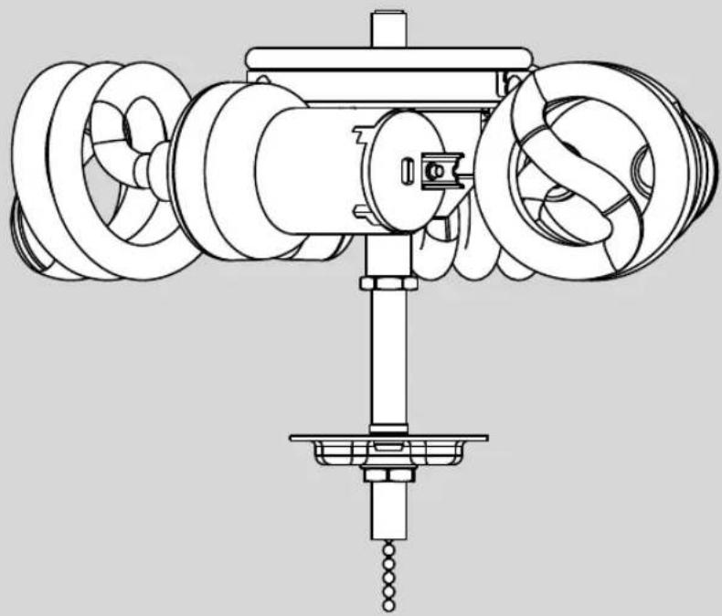
Technical line drawing of a mechanical assembly with rotating components and a base mount (no text or symbols)Model 99025
Compatible with:
2xxxx Types A - Z
Read entire installation instructions carefully before beginning installation and save these instructions.

Your light kit is compatible with most ceiling fans. The light kit will attach to the fan's switch housing. Begin on page 3 where you will choose the type of switch housing that most closely resembles the one on your fan. From there, you will be directed to the set of assembly instructions that are appropriate for installing the light kit to your fan.
READ AND SAVE THESE INSTRUCTIONS
This product conforms to UL Standard 507.
⚠️ WARNINGS
w.1 - To reduce the risk of fire, electrical shock, or personal injury, mount fan directly from building structure and/or an outlet box marked acceptable for fan support of 70 lbs. (31.8 kg) and use the mounting screws provided with the outlet box.
w.2 - To avoid possible electrical shock, before installing or servicing your fan, disconnect the power by turning off the circuit breakers to the outlet box and associated wall switch location. If you cannot lock the circuit breakers in the off position, securely fasten a prominent warning device, such as a tag, to the service panel.
CAUTIONS
c.1 - All wiring must be in accordance with national and local electrical codes ANSI/NFPA 70. If you are unfamiliar with wiring, use a qualified electrician.

WHICH ASSEMBLY METHOD WILL I USE?
Choose one of the four images below that most closely resembles the switch housing on your fan; then follow the instructions under the image.

If your fan's switch housing cap resembles this one, remove the cap screws with a Phillips head screwdriver. Then follow the TYPE-A ASSEMBLY INSTRUCTIONS on pages 4-5.

If your fan's switch housing cap resembles this one, remove the whole switch housing by removing the switch housing screws with a Phillips head screwdriver. Remove the two cap screws from the inside of the switch housing. Reinstall the switch housing. Tighten the switch housing screws. Then follow the TYPE-A ASSEMBLY INSTRUCTIONS on pages 4-5.
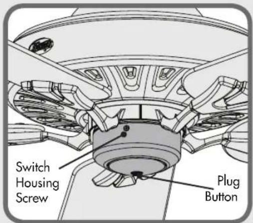
If your fan's switch housing cap resembles this one, remove the whole switch housing by removing the switch housing screws with a Phillips head screwdriver. Remove the plug button. Then follow the TYPE-B ASSEMBLY INSTRUCTIONS on pages 6-7.

If your fan's switch housing cap resembles this one, remove the whole switch housing by removing the switch housing screws with a Phillips head screwdriver. Remove the plug button using a standard screwdriver. Then follow the TYPE-C ASSEMBLY INSTRUCTIONS on pages 8-9.
TYPE-A ASSEMBLY INSTRUCTIONS

If your fan does not have pin connectors on the wires coming from the switch housing, install the wiring harness provided. Using the provided wire connectors connect the white wire from the fan to the white wire from the wire harness and connect the black or blue wire from the fan to the black wire from the wire harness.

Screw the two light kit screws halfway into the switch housing. Using the single pin connectors, connect the black or blue wire from the fan to the black wire from the light kit. Connect the white wire from the fan to the white wire from the light kit.

Lift the light kit up to meet the lower switch housing. Attach the light kit to the switch housing using the keyhole slots to engage the light kit screws. Rotate clockwise. Tighten screws securely through the access holes.
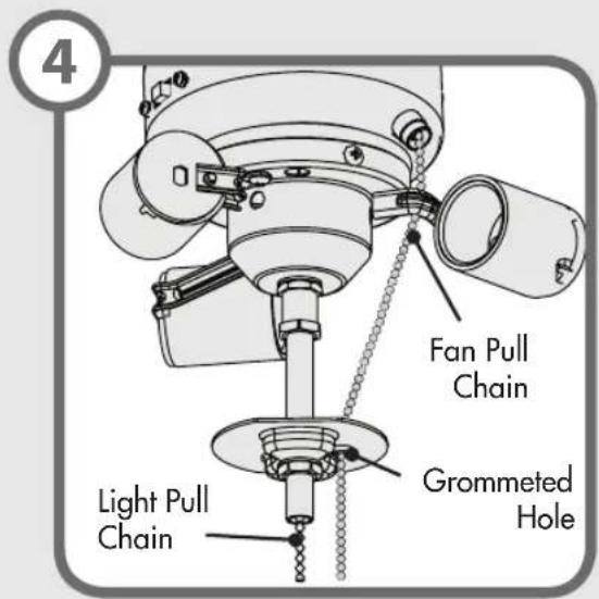
If necessary, attach the extension chain provided to the fan pull chain coming from the switch housing. Then feed the end of the extension chain through the grommeted hole in the light kit.
TYPE-A ASSEMBLY INSTRUCTIONS (CONTINUED)

Installing the bulb - Install a bulb into each socket. When necessary, replace bulbs with bulbs of same type and wattage.

Installing the globe (sold separately) - Press the globe flush against the metal plate. Thread the light pull chain through the hole in the center of the finial cap and thread the fan pull chain through the hole in the side of the cap. Finally, thread only the light pull chain through the hole in the finial and screw the finial onto the threaded rod.

Installing the Pull chain pendant -
Attach the pull chain pendants to the end of the short chains coming from the switch housing and the light kit. Turn on power. Your installation is complete!
TYPE-B ASSEMBLY INSTRUCTIONS

If your fan does not have pin connectors on the wires coming from the switch housing, install the wiring harness provided. Using the provided wire connectors connect the white wire from the fan to the white wire from the wire harness and connect the black or blue wire from the fan to the black wire from the wire harness.
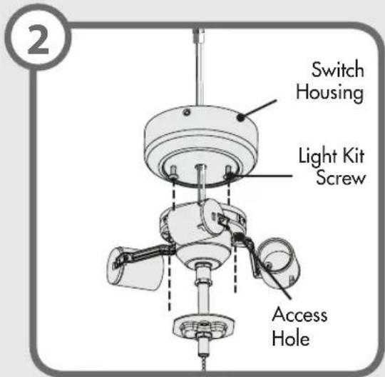
Screw the two light kit screws halfway into the switch housing. Feed the light kit wires through the center hole in the switch housing. Lift the light kit up to meet the lower switch housing. Attach the light kit to the switch housing using the keyhole slots to engage the light kit screws. Rotate clockwise. Tighten screws securely through the access holes.

natural_image
Technical diagram of a ceiling fan assembly with labeled parts (no text or symbols present)Using the single pin connectors, connect the black or blue wire from the fan to the black wire from the light kit. Connect the white wire from the fan to the white wire from the light kit.

Lift the light kit assembly up so that the screw holes in the lower switch housing line up with the holes in the upper switch housing. Install the switch housing screws and tighten securely.
TYPE-B ASSEMBLY INSTRUCTIONS (CONTINUED)

If necessary, attach the extension chain provided to the fan pull chain coming from the switch housing. Then feed the end of the extension chain through the grommeted hole in the light kit.

Installing the bulb - Install a bulb into each socket. When necessary, replace bulbs with bulbs of same type and wattage.
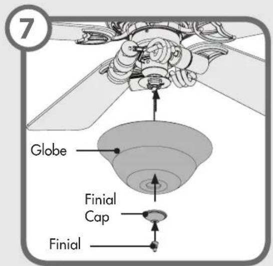
Installing the globe (sold separately) -
Press the globe flush against the metal plate. Thread the light pull chain through the hole in the center of the finial cap and thread the fan pull chain through the hole in the side of the cap. Finally, thread only the light pull chain through the hole in the finial and screw the finial onto the threaded rod.
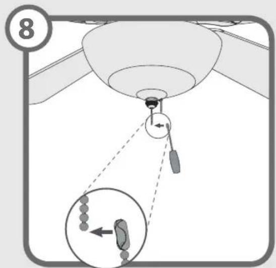
Installing the pull chain pendant -
Attach the pull chain pendants to the end of the short chains coming from the switch housing and the light kit. Turn power on. Your installation is complete.
TYPE-C ASSEMBLY INSTRUCTIONS
1
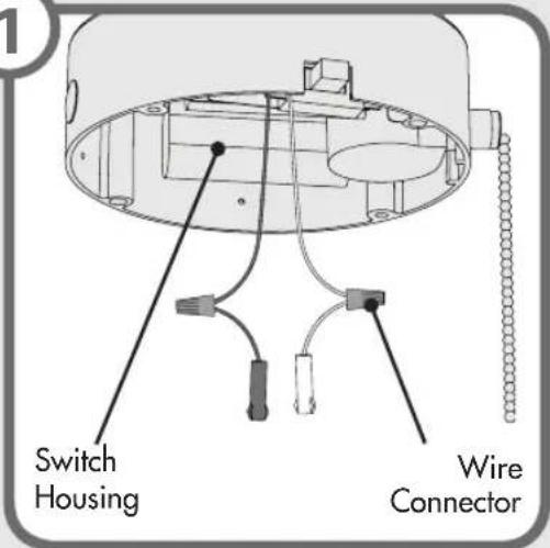
If your fan does not have pin connectors on the wires coming from the switch housing, install the wiring harness provided. Using the provided wire connectors connect the white wire from the fan to the white wire from the wire harness and connect the black or blue wire from the fan to the black wire from the wire harness.
2
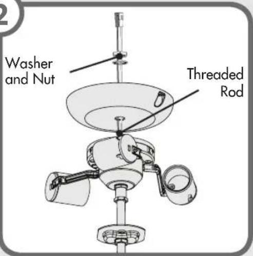
Feed the wires through the switch housing cap, washer, and nut. Then install the switch housing cap by twisting clockwise onto the threaded rod. Install the washer and nut onto threaded rod and tighten securely.
3
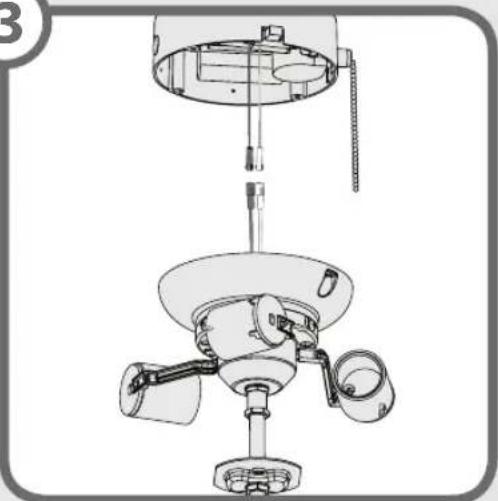
natural_image
Technical line drawing of a ceiling lamp mechanism with three blades and central hub (no text or symbols)Using the single pin connectors, connect the black or blue wire from the fan to the black wire from the light kit. Connect the white wire from the fan to the white wire from the light kit.
4
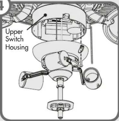
Lift the light kit assembly up so that the screw holes in the lower switch housing line up with the holes in the upper switch housing. Install the switch housing screws and tighten securely.
TYPE-C ASSEMBLY INSTRUCTIONS (CONTINUED)

If necessary, attach the extension chain provided to the fan pull chain coming from the switch housing. Then feed the end of the extension chain through the grommeted hole in the light kit.
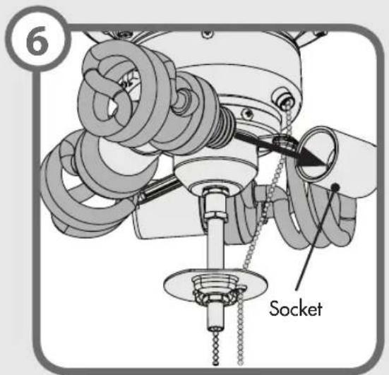
Installing the bulb - Install a bulb into each socket. When necessary, replace bulbs with bulbs of same type and wattage.

Installing the globe (sold separately) - Press the globe flush against the metal plate. Thread the light pull chain through the hole in the center of the finial cap and thread the fan pull chain through the hole in the side of the cap. Finally, thread only the light pull chain through the hole in the finial and screw the finial onto the threaded rod.

Installing the pull chain pendant - Attach the pull chain pendants to the end of the short chains coming from the switch housing and the light kit. Turn power on. Your installation is complete.
TROUBLESHOOTING
Lights don't come on.
• Make sure that the bulbs are properly installed.
• Make sure power switch is on.
- Pull the pull chain to make sure it is on.
- Check the circuit breaker to ensure the power is turned on.
- Check the pin connections in the light kit.
- Refer to the fan manual for locating the fan's wiring. Verify that the light and power wires are correctly connected to the ceiling and the light kit.
ONE YEAR WARRANTY
This product is warranted to the original purchaser by Casablanca Fan Company/Hunter Fan Company against defects in material and workmanship for one (1) year from date of purchase. During the warranty period, we will repair or, at our option, replace a defective product at no charge. For information on how to obtain service, contact the Casablanca/Hunter Service Department by calling our toll-free number at 888-830-1326. Damage to the product caused by mishandling, improper installation or modification is not covered by this warranty. This warranty is given in lieu of all other warranties expressed or implied. Some states do not allow limitations of time on an implied warranty, therefore the above limitations may not apply in every case. This warranty states specific legal rights which may vary from state to state.
If you have problems installing or operating your light kit, do not return this product to the dealer. Call our Consumer Affairs Hotline.
888-830-1326
- Ultra-Bright Bowl Fitter Ultra-Bright
- Installation Manual
- READ AND SAVE THESE INSTRUCTIONS
- ⚠️ WARNINGS
- CAUTIONS
- WHICH ASSEMBLY METHOD WILL I USE?
- TYPE-A ASSEMBLY INSTRUCTIONS
- TYPE-A ASSEMBLY INSTRUCTIONS (CONTINUED)
- TYPE-B ASSEMBLY INSTRUCTIONS
- TYPE-B ASSEMBLY INSTRUCTIONS (CONTINUED)
- TYPE-C ASSEMBLY INSTRUCTIONS
- TYPE-C ASSEMBLY INSTRUCTIONS (CONTINUED)
- TROUBLESHOOTING
- Lights don't come on.
- ONE YEAR WARRANTY
Brand : Casablanca
Model : 99025
Category : Lighting Kit for Ceiling Fan