
AFR4CC - Cable duct Panduit - Free user manual and instructions
Find the device manual for free AFR4CC Panduit in PDF.


| Product Type | Rack Mount Cable Management Panel |
| Model Number | AFR4CC |
| Brand | Panduit |
| Rack Units | 4U |
| Width | 19 inches (483 mm) |
| Depth | 6 inches (152 mm) |
| Height | 7 inches (178 mm) |
| Weight | 3.5 lbs (1.6 kg) |
| Material | Steel with black powder coat finish |
| Front Cover | Removable, ventilated |
| Cable Entry | Top and bottom brush strips |
| Mounting Type | 19" rack mount with front and rear brackets |
| Compatibility | Standard EIA-310 racks |
| Maximum Cable Capacity | Up to 120 Cat6a cables |
| Operating Temperature | 32°F to 122°F (0°C to 50°C) |
| Storage Temperature | -40°F to 158°F (-40°C to 70°C) |
| Cleaning Instructions | Wipe with a dry cloth; do not use solvents |
| Warranty | 5 years limited |
Frequently Asked Questions - AFR4CC Panduit
User questions about AFR4CC Panduit
0 question about this device. Answer the ones you know or ask your own.
Ask a new question about this device
Download the instructions for your Cable duct in PDF format for free! Find your manual AFR4CC - Panduit and take your electronic device back in hand. On this page are published all the documents necessary for the use of your device. AFR4CC by Panduit.
USER MANUAL AFR4CC Panduit
| Raceway Channel | See Fig. | Electrical Cables | Data Grade Cables | |||||||
| 14 | 12 | 10 | 24 AWG | 24 AWG | 24 AWG | |||||
| THN/THWN/T90 | Cat 6 | Cat 6A | Cat 6A (SD) | |||||||
| 0.111 | 0.13 | 0.164 | 0.24 | 0.3 | 0.24 | |||||
| Fill | Fill | Fill | Fill | |||||||
| Max | Max | Max | Spec | Max | Spec | Max | Spec | Max | ||
| UL Temp Rise Test | 40% | 60% | 40% | 60% | 40% | 60% | ||||
| Outer Channels (with screws installed) | A | 21 | 15 | 10 | 3 | 4 | 2 | 3 | 3 | 4 |
| Inner Channels | B | 24 | 17 | 11 | 3 | 5 | 2 | 3 | 3 | 5 |


natural_image
Three circular diagrams showing different types of screw heads, with no text or symbols present.Themountinghardwareusedtosecure theracewayshallbeappropriateforthe mountingsurface.

Screwsprovidedwithracewayare intendedforinstallationonaconcrete surface.
NOTES:
- An adhesive strip may serve only as a positioning aid during the installation process. The raceway shall be secured by mechanical fastening means.
- Holes for mounting raceway and associated fittings should be predrilled into infrastructure prior to the installation of the mounting hardware.
•A5/32"concretedrillbitisneededfortheprovidedconcretescrews.
BASE&COVER

COUPLER


natural_image
Pure technical line drawing of a mechanical assembly without any text, numbers, or symbols

natural_image
Simple line drawing of a rectangular object with a circular element above it (no text or symbols)
natural_image
Technical line drawing of a structural component with an arrow indicating direction (no text or symbols)Staggerbase jointandcover couplingjointto strengthen assembly.
RIGHTANGLE

natural_image
Technical line drawing of a multi-tiered mechanical component with screw holes and mounting holes (no text or symbols)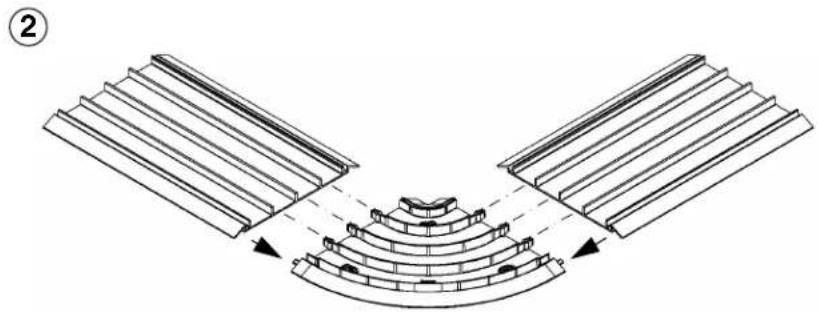
natural_image
Diagram of a mechanical or structural assembly with two symmetrical components and directional arrows indicating flow or movement (no text or symbols)
natural_image
Technical diagram of a layered structure with directional arrows indicating flow or movement (no text or symbols present)
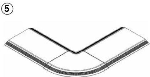
natural_image
Pure technical line drawing of a V-shaped component without any text, numbers, or symbolsTRANSITIONTOT70


natural_image
Technical diagram showing a structural assembly with arrows indicating direction (no text or symbols present)
natural_image
Technical line drawing of a mechanical assembly with numbered components (no text or symbols)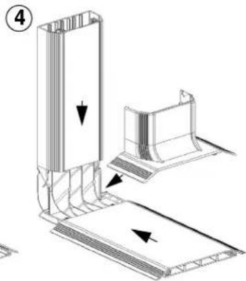
natural_image
Technical diagram showing a mechanical assembly with directional arrows indicating movement or force (no text or symbols present)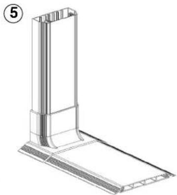
natural_image
Technical line drawing of a vertical structural component with a base and side panel (no text or symbols)ENDCAP
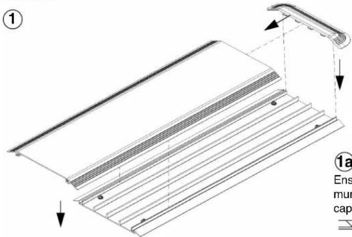
1a
Ensureendcapandcoverarefullyengagedasshown.0.3"ismaximumallowabledistancebasecanextendbeyondcoverwheninstalling cap.


natural_image
Line drawing of a rectangular metal frame with internal grooves, labeled with number 2 (no text or symbols on the frame itself)JUNCTIONBOX

1a
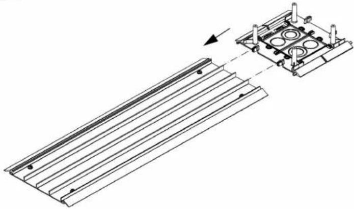
Ensureendcapand coupler(s)connectto junctionboxcoveras shown[8places]
Note: JunctionBoxcanbeassembledbetweenworacewaypathswiththeuseoftwocouplerfittings. Endcapinstallationsshownasreference.
②
natural_image
Technical line drawing of a mechanical assembly with a bracket and mounting base (no text or symbols)③

natural_image
Technical line drawing of a metal beam assembly with mounting holes and structural supports (no text or symbols)
BREAKOUTSFORCONDUITAPPLICATIONS
DIVIDEDINSERTAPPLICATIONPOWER/DATAAPPLICATIONDATAAPPLICATIONPOWERAPPLICATION
4

5
6

natural_image
Technical line drawing of a mechanical device with a control panel and roller assembly (no text or symbols)
natural_image
Technical line drawing of a mechanical component with a rectangular base and four circular top ports (no text or symbols)WALLTRANSITION
GREENFIELDAPPLICATIONS-NEWCONSTRUCTION
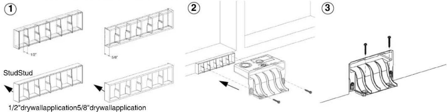
1/2"drywallapplication5/8"drywallapplication
Determine if you will use 1/2" or 5/8" drywall. Orient standoffasshownfordesiredapplication.
lfinstallingintoexistinginfrastructure,continuetoBrownfieldapplicationinstructions.
Securebasetosoleboardandroute cablesandwiringasdesired.Donot overtightenscrewsasflooringinstallationmayrequireadjustments.
Adjustwalltransitionfittingbaseheight duringflooringinstallation.Afterdrywall andflooringhavebeeninstalled,secure transitionfittingbasetothefloorusing appropriatehardware.
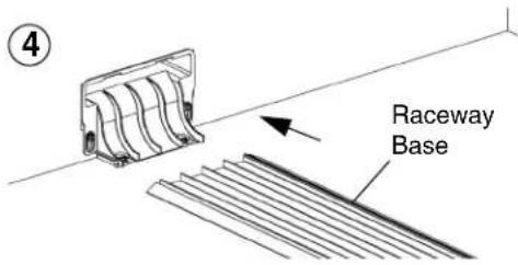
ContinuewithStep4ofBrownfieldapplicationinstructions.
**OnlyusestandofforGreenfield applications**
BROWNFIELDAPPLICATIONS-EXISTINGINFRASTRUCTURE

Cutholeindrywallbetweenstudstothe dimensionsshown.

natural_image
Technical line drawing of a mechanical component with an arrow indicating direction (no text or symbols)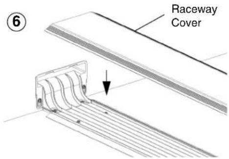
natural_image
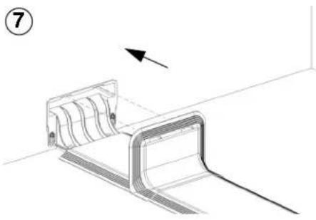
Technical line drawing of a mechanical component with an arrow indicating direction (no text or symbols)
natural_image
Simple line drawing of a bent metal bracket with a diagonal line extending from its side (no text or symbols)TABLELEG
INSTALLATIONBETWEEN2RACEWAYCHANNELS

natural_image
Technical line drawing of a structural support frame with columns and a vertical column (no text or symbols)①

Centeroftablelegtransitionfittingwillsitapproximately3-1/4"fromtheedgeoftheracewaycover.
Routecablespriortoinstallingtheracewaycover.
NOTE: Desired hole in table should be offset from table leg center to accommodate proper mountingoftableleg.
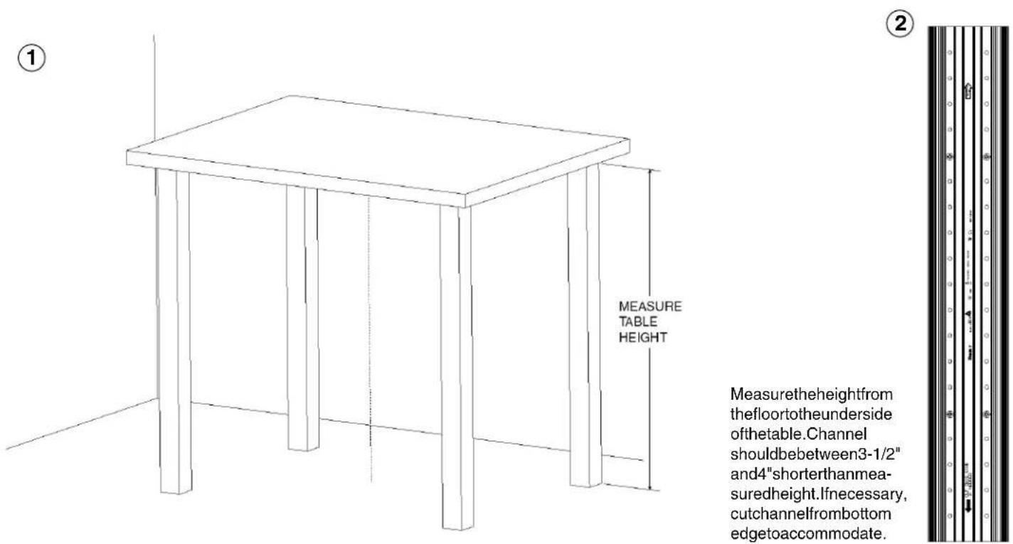
Measuretheheight fromthefloortothe undersideofthetable. Channelshouldbe between3-1/2"to4" shorterthanthemeasuredheight.Ifnecessary,cutchannelfrom bottomedgetoaccommodate.
2

③

④

Securemountingbrackettotopofchannelusingprovidedhardware. Usethetopholeofthechannelforassembly.Donotfullytightenthe mountingbracketatthistime.
5

natural_image
Technical line drawing of a mechanical device with no visible text or symbols5A
natural_image
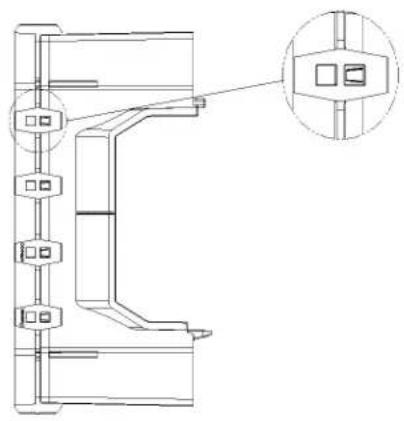
Technical line drawing of a mechanical bracket assembly with mounting holes and a close-up inset showing a control panel (no text or symbols)Ensurecouplersconnecttobottomtransition bootsasshown. [4Places]
6

natural_image
Technical line drawing of a mechanical component with grid lines and a bracket (no text or symbols)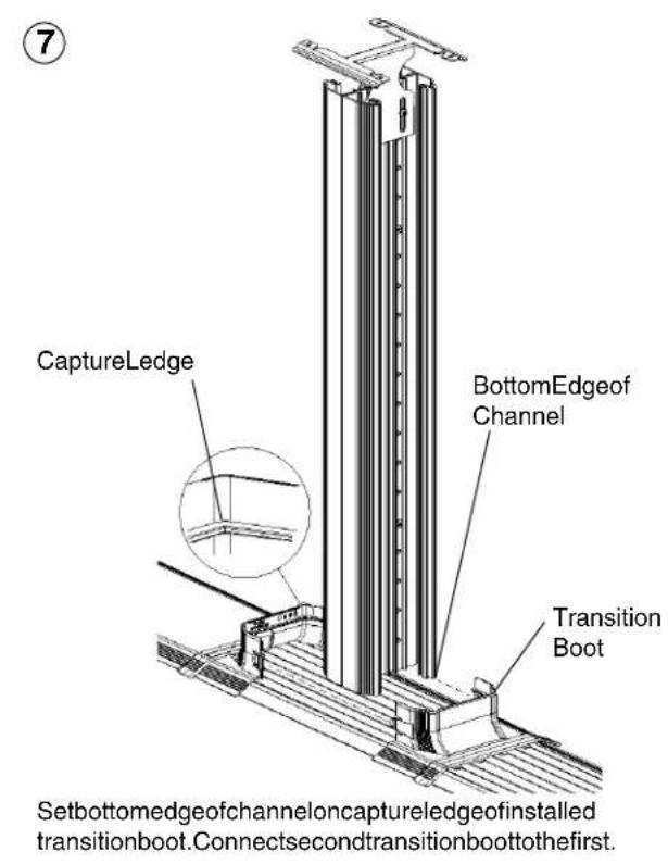
![#8-32x3/4" Wood Screws [4Places] Ensurechannelislevel.Securemountingbrackettoundersideoftable usingprovidedhardware.Fullytightenmountingbracketscrewsto securechannelinplace.](/content/2026/05/985712/images/46943c7181736e4865a7573d36d020f71fca6e74d46cb8bc86019bbaaa6dabe8.jpg)
![#10-32Hex Nuts [2Places] #10-32x3/8" HexScrews [2Places] Cover [2Places]](/content/2026/05/985712/images/2a1ac3f6c767108fdfc044ed94953fcbde70084d74186e86916946965401d05e.jpg)
![10 SteppedFlange [2Places] MountingBracket TransitionBoot Latch [4Places] TopTransitionBoot [2Places]](/content/2026/05/985712/images/8ed9f3ee37ca7c1558cf1400325c221e17024fdbf944c67e1a410a989a6af713.jpg)
Routecablespriortoinstallingcovers.Coversaretamper-proof andarenotintendedforeasyremoval.
Assembletoptransitionbootstoeachother. Transitionbootlatcheswill mounttothesteppedflangesofthemountingbracket.
Ifaddedstiffnessisdesired,securebottomofchannelusingprovidedhardwareinthelowermostholesofthechannel.
11

natural_image
Technical line drawing of a mechanical assembly with a vertical column and support structure (no text or symbols)INSTALLATIONASSTANDALONEORWITHSINGLESIDERACEWAYCHANNEL
natural_image
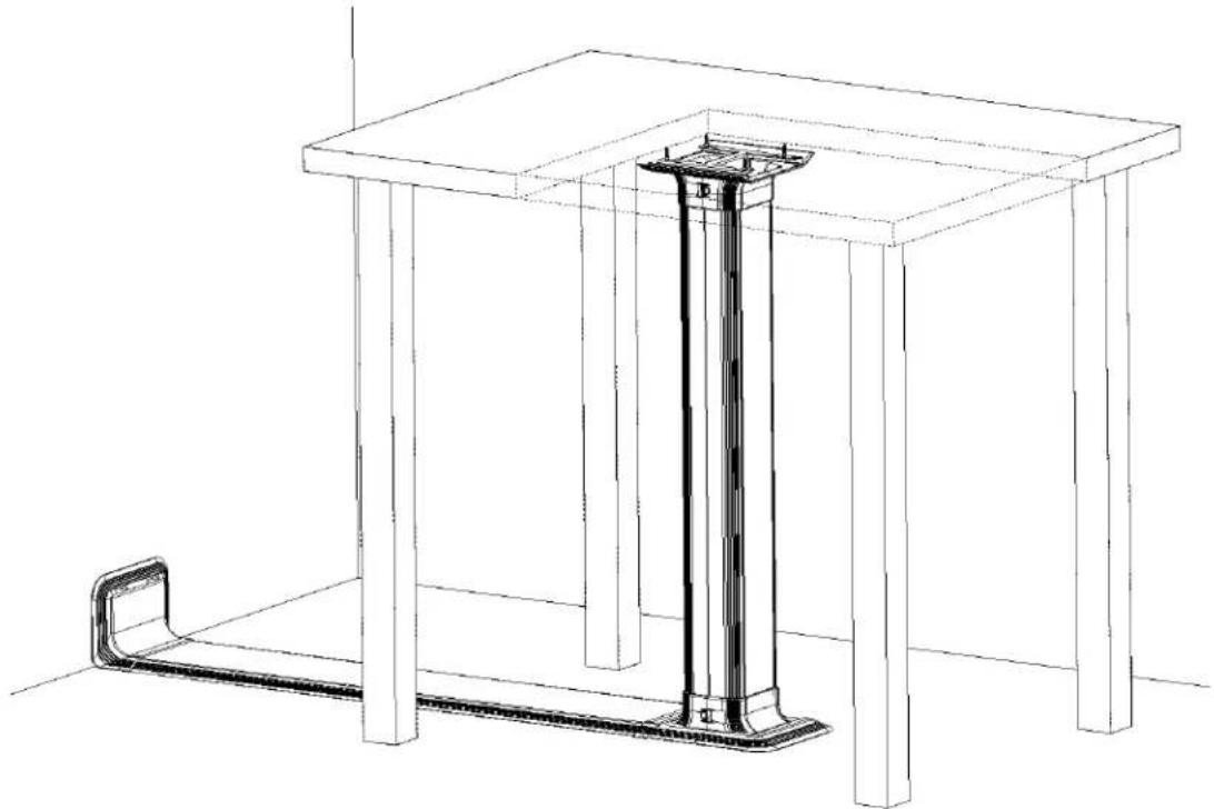
Technical line drawing of a table with columns and a vertical support structure (no text or symbols)NOTE: For single side raceway application; above floor raceway should be mounted prior to table leg installation. Centeroftablelegwillsitapproximately3-1/4"fromtheedgeoftheracewaycover.Routecablespriorto installingtheracewaycover.
natural_image
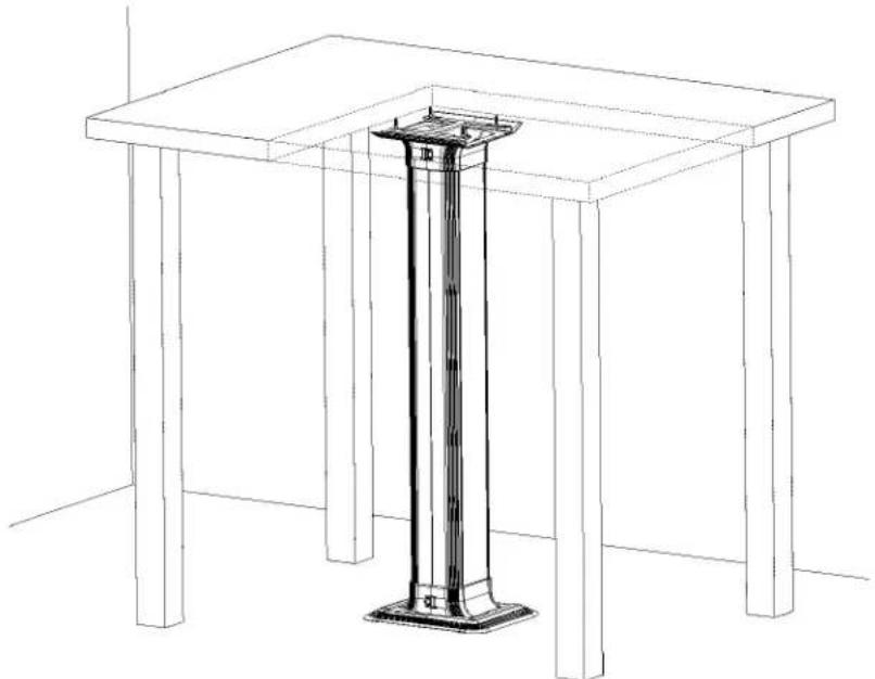
Line drawing of a simple table with a vertical metal column and base, no text or symbols presentNOTE: Desired hole in table should be offset from table leg center to accommodate proper mounting of table leg.
NOTE: Desired hole in table should be offset from table leg center to accommodate proper mounting of table leg.

![3B Bottomof Channel BottomHole ofChannel [2Places] Mounting Bracket](/content/2026/05/985712/images/37648eef9b34fd74ddc97cb439f7cdb6647a8f55989044d29699c8b0f4a4aba5.jpg)
©PanduitCorp.2019
INSTALLATIONINSTRUCTIONS
PN616B
4

Securemountingbracketstotopandbottomofchannelusingprovided hardware. Usetheholesclosesttotheendsofthechannelforassembly. Donotfullytightenthemountingbracketatthistime.

Pre-drillholesininfrastructureifnecessary.Secure bottommountingbrackettofloorwithproperhardware.(Concretescrewsprovided)
6
![#8-32x3/4"Wood Screws[4Places]](/content/2026/05/985712/images/cee3cf8d50af97e1768550292f3097419b6aa33b1f0044c734d30a59cd18c71f.jpg)
Ensurechannelislevel.Securetopmounting brackettoundersideoftableusingprovided hardware.

TransitionBootLatch
![7A Ensureendcap(s)or coupler(s)connectto bottomtransition bootsasshown [4places]](/content/2026/05/985712/images/b2923a5b443320074d1554d126444ce855bf6ae47cf315457041df3263c46b08.jpg)

Assemblebottomtransitionbootstogether.Transitionboot latches(showninstep7)willmountosteppedflangesofthe mountingbrackets.Placebottomofchannelontopofcap-tureledgeoftransitionboots.
Tightenallmountingbracketscrewstothechannelatthis time.
![⑨ Covers [2Places]](/content/2026/05/985712/images/b764a9aed1d7a3090ac0b9a054dd6680a4313f814b7da78536e6a37ba6c04578.jpg)
Routecablespriortoinstallingcovers.Coversaretamper proofandarenotintendedforeasyremoval.
![10 Stepped Flange [2Places] Transition Boot Latch [4Places] Assembletoptransition bootstoeachother.Transitionbootlatcheswill mounttothestepped flangesofthemounting bracket.](/content/2026/05/985712/images/b9078f80ed59c82a4f67090f391dea6cd181206a08d0b2b26da8f6f0815c1534.jpg)
11

natural_image
Line drawing of a simple table with four legs and a vertical column base (no text or symbols)Brand : Panduit
Model : AFR4CC
Category : Cable duct