
PAML-CP-186-HP3-G114 - Motherboard Festo - Free user manual and instructions
Find the device manual for free PAML-CP-186-HP3-G114 Festo in PDF.


| Brand | Festo |
| Model | PAML-CP-186-HP3-G114 |
| Product Type | Industrial Motherboard / Controller |
| Dimensions (approx.) | 105 mm x 70 mm x 30 mm (L x W x H) |
| Weight (approx.) | 0.2 kg |
| Power Supply | 24 V DC ±10% |
| Power Consumption | Max. 10 W |
| Processor | High-performance industrial microcontroller |
| Memory | Integrated flash and RAM |
| Communication Interfaces | Ethernet, CANopen, RS-232 |
| Digital I/O | 8 inputs / 8 outputs, 24 V DC |
| Analog I/O | 2 inputs / 2 outputs, 0-10 V or 4-20 mA |
| Operating Temperature | -20°C to +60°C |
| Protection Rating | IP20 (suitable for control cabinet) |
| Mounting | DIN rail or screw mounting |
| Main Functions | Logic control, sequence control, communication hub, data processing |
| Cleaning & Maintenance | Use a dry, lint-free cloth; avoid liquids. Disconnect power before cleaning. |
| Safety Precautions | Follow ESD guidelines; use only specified power supply; do not open device. |
| Spare Parts & Repairability | Contact Festo service for repair; no user-serviceable parts inside. |
| Certifications | CE, UL, RoHS |
Frequently Asked Questions - PAML-CP-186-HP3-G114 Festo
User questions about PAML-CP-186-HP3-G114 Festo
0 question about this device. Answer the ones you know or ask your own.
Ask a new question about this device
Download the instructions for your Motherboard in PDF format for free! Find your manual PAML-CP-186-HP3-G114 - Festo and take your electronic device back in hand. On this page are published all the documents necessary for the use of your device. PAML-CP-186-HP3-G114 by Festo.
USER MANUAL PAML-CP-186-HP3-G114 Festo
natural_image
Technical drawings of three mechanical components with mounting holes and mounting flanges (no text or symbols)Assembly instructions
8161951
2021-10b
[8161953]

8161951
Translation of the original instructions
© 2021 all rights reserved to Festo SE & Co. KG
1 Applicable documents
i
All available documents for the product→ www.festo.com/sp.
2 Safety
2.1 Safety instructions
- Only use the product in its original condition without unauthorised modifications.
- Only use the product if it is in perfect technical condition.
- Take the weight of an individual device or a service unit into account. Dependent on the design, a mounted service unit can weigh more than 100 kg.
- Under intended use the surface temperature may reach 60 °C. Allow the device to cool down before working on it.
- Make sure the mounting surface is sufficiently strong for the maximum forces.
- Only use suitable mounting components.
-Mount the individual device or the service unit only on flat surfaces.
2.2 Intended use
–The sub-base PAML-CP serves as an adapter for the pneumatic connection and for pipe mounting for in-line installation of service units.
–The module connector PAML-MK is used to connect two service units of the same size.
2.3 Training of qualified personnel
Work on the product may only be carried out by qualified personnel who can evaluate the work and detect dangers. Personnel must have the relevant mechanical training.
3 Additional Information
- Accessories → www.festo.com/catalogue.
4 Product Range Overview
4.1 Scope of delivery

flowchart
graph TD
    A["5"] --> B[" "]
    C["4"] --> D[" "]
    E["3"] --> F[" "]
    G[" "] --> H[" "]
    I[" "] --> J[" "]
    K[" "] --> L[" "]
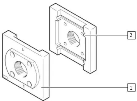
Fig. 1: Sub-base PAML-CP
1
Front plate (1x)
2
Rear plate (1x)
3
Screw (8x)
4
Washer (8x)
5
O-ring (2x)


Fig. 2: Module connector PAML-MK
6
Screw (2x)
7
Front plate (1x)
8
O-ring (1x)
9
Rear plate (1x)
4.2 Not in scope of delivery


Fig.3
10
Electrical pressure regulator (1x) PREL-186
11
Micro filter (1x) PFML-186
5 Assembly
5.1 Mounting the connecting plates PAML-CP

Fig.4
- Orient the front plate 1 and the rear plate 2 so the stamp number on the sub-base corresponds with the stamp number on the housing (1 to 1 and 2 to 2) and the mounting thread 12 for wall mounting points to the rear.
- Insert the O-rings 5 in the slots provided.
- Position the front plate 1 and the rear plate 2.
- Fasten the front plate 1 and the rear plate 2 to the service unit using four screws 3 and four washers 4. Tightening torque: 27 Nm ± 15%
- Comply with the maximum screw-in depth for the pipe connection.
ISO 228 Max. screw-in depth [mm]
| G1/2 12 | |
| G1 1/4 20 | |
| G1 1/2 22 | |
| G2 24 | |
| G2 1/2 26 |
5.2 Assembly of the module connector PAML-MK

Fig.5
- Note the flow direction from 1 to 2. The numbers 13 on the product housing serve as orientation.
- Insert the retaining screws 6 through the holes in the front plate 7.
- Place the seal 8 between the service units.
- Place the front plate 7 and the rear plate 9 in the slots of the service units.
- Tighten the screws 6. Tightening torque: 40 Nm ± 25%
5.3 Wall mounting

The M12 threads on the sub-bases and module connectors can be used to mount individual devices or service units on the wall or a machine frame.

The grid dimension width for distributor block PMBL-186-HP3 is 93 mm.
The grid dimension width between the sub-bases and module connectors is 186 mm as standard, and the hole spacing is 145 mm in height.

Fig.6
- Fasten all sub-bases and module connectors with two screws M12 14 each. The screw-in depth must be at least 15 mm and maximum 18 mm. Maximum tightening torque: 42 Nm
6 Disassembly
- Depressurise the system.
- Check the surface temperature of the device. If necessary, let the device cool down.
- Remove the existing service unit string.
7 Technical data
| PAML -CP -MK | ||
| Operating pressure [MPa] 0 ... 5 | ||
| [bar] 0 ... 50 | ||
| [psi] 0 ... 72$ | ||
| Temperature of medium [°C] +5 ... +60 | ||
| Ambient temperature [°C] +5 ... +60 | ||
Tab. 1: Technical data
Brand : Festo
Model : PAML-CP-186-HP3-G114
Category : Motherboard