P.BE-CPEA-CL-IT - Pneumatic module Festo - Free user manual and instructions
Find the device manual for free P.BE-CPEA-CL-IT Festo in PDF.


| Brand | Festo |
| Model | P.BE-CPEA-CL-IT |
| Product Type | Pneumatic Module |
| Series | CPEA |
| Dimensions (W x H x D) | Approx. 100 mm x 50 mm x 30 mm |
| Weight | Approx. 200 g |
| Power Supply Voltage | 24 V DC |
| Operating Pressure Range | 4 to 7 bar |
| Maximum Flow Rate | 300 l/min |
| Port Size | G1/8" |
| Number of Solenoid Valves | 2 (dual) |
| Electrical Connection | M12, 5-pin |
| Protection Class | IP65 |
| Ambient Temperature Range | -5°C to +50°C |
| Medium | Compressed air, filtered and lubricated |
| Main Functions | Pneumatic valve actuation, electrical signal conversion |
| Maintenance | Clean with dry cloth; inspect connections regularly |
| Cleaning | Do not use solvents; wipe with damp cloth |
| Safety Precautions | Disconnect power before servicing; use personal protective equipment |
| Spare Parts Availability | Available from Festo authorized distributors |
| Repairability | Field replaceable solenoids and gaskets |
| Certifications | CE, RoHS |
| Manual Language | English (original) |
Frequently Asked Questions - P.BE-CPEA-CL-IT Festo
User questions about P.BE-CPEA-CL-IT Festo
0 question about this device. Answer the ones you know or ask your own.
Ask a new question about this device
Download the instructions for your Pneumatic module in PDF format for free! Find your manual P.BE-CPEA-CL-IT - Festo and take your electronic device back in hand. On this page are published all the documents necessary for the use of your device. P.BE-CPEA-CL-IT by Festo.
USER MANUAL P.BE-CPEA-CL-IT Festo
natural_image
Exterior view of a PESTO brand mechanical component with multiple mounting holes (no text or symbols visible on body)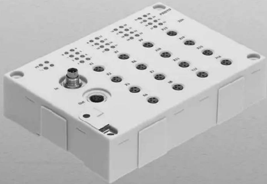
natural_image
White electronic device with multiple ports and connectors, no visible text or symbolsFESTO
Description Manual
CPI-CLmodules:
-CP-E08-M12-CL
-CP-E08-M8-CL
-CP-E16-KL-CL
-CP-A04-M12-CL
CPI-ELmodules
-CP-E32-M8-EL
-CP-E16-M8-EL
-CP-E16-M12-EL
-CP-A08-M12-EL-Z


Description
539300
en0711a
[726334]
Contentsandgeneralsafetyinstructions
OriginalGermantext......
Editionen0711a......
DesignationP.BE-CPEA-CL-EN......
Order-no.539300......
© (Festo SE & Co. KG, D-73726 Esslingen, Federal Republic of Germany, 2007) Internet: http://www.festo.com
E-mail: service_international@festo.com
The copying, distribution and utilization of this document as well as the communication of its contents to others without expressed authorization is prohibited. Violations give rise to compensation. All rights are reserved, in particular the right to carry out patent, utility model or ornamental design registration.
Contentsandgeneralsafetyinstructions
Contents
Intended use ....
Selecting the power unit ....
Target group ....
ServiceVII....
ImportantuserinstructionsVIII......
NotesontheuseofthismanualX
1. System overview CPI/CP system ....
1.1 Setting up CPI systems ....
1.1.1 Method of operation of the CPI/CP system ....
1.1.2 Rules for extending the CPI system .....
1.1.3 Use of the I/O modules 1-1
1.1.4 Basic rules for addressing 1-1
2. Inputmodules types CP-E08-M...-CL and CP-E16-KL-CL
2.1 Function of the input modules CP-E08-M...-CL and CP-E16-KL-CL .....
2.1.1 Display and connecting elements ....
2.2 Mounting....
2.3 Installation ....
2.3.1 Connecting sensors ....
2.3.2 Connect the input module to the CP string 2-1
2.4 Diagnosis ....
2.4.1 Diagnosis via LEDs . . . 2-1
2.4.2 Diagnosis via the field bus 2-1
3. Output module type CP-A04-M12-CL .....
3.1 Function of output module type CP-A04-M12-CL .....
3.1.1 Display and connecting elements 3-
3.2 Mounting....
3.3 Installation ....
3.3.1 Connecting the actuators 3-
3.3.2 Connect the output module to the CP string 3-8
3.4 Diagnostics 3-10
3.4.1 Diagnostics via LEDs 3-10
3.4.2 Diagnostics viathefieldbus3-13....
- Input modules type CP-E16-M...-EL and CP-E32-M8-EL 4-1
4.1 Functionofthe input modules CP-E16-M...-EL and CP-E32-M8-EL 4-3
4.1.1 Display and connecting elements 4-4
4.2Mounting ..... 4-7
4.3Labellingof inscription label holder 4-9
4.4 Installation 4-10
4.4.1Connectingsensors 4-11
4.4.2 Connect the input module to the CP string 4-14
4.5 Diagnostics 4-16
4.5.1 Diagnostics via LEDs 4-16
4.5.2 Diagnostics using fieldbus . 4-20
- Output module type CP-A08-M12-EL-Z 5-1
5.1 Function of the output module type CP-A08-M12-EL-Z 5-3
5.1.1 Display and connecting elements 5-4
5.2 Mounting 5-5
5.3 Labelling of inscription label holder 5-7
5.4 Installation 5-8
5.4.1 Connect external load supply 5-9
5.4.2 Connectingtheactuators .. 5-10
5.4.3 Connect the output module to the CP string 5-11
5.5 Diagnostics 5-13
5.5.1 Diagnostics via LEDs 5-13
5.5.2 Diagnostics using fieldbus 5-16
A. Technical appendix ...... A-1
A.1 Technical specifications A-3
A.1.1 General technical data A-3
A.1.2 Technical specifications of the CL input modules A-4
A.1.3 Technical specifications of the CL output modules ..... A-6
A.1.4 Technical specifications of the ELinputmodulesA-7......
A.1.5 Technical specifications of the EL output modules A-9.....
A.2InternalstructureoftheinputsA-10.....
A.2.1InternalstructuretypeCP-E32-M8-ELA-10....
A.2.2 Internal structure type CP-E08-M12-CL and CP-E16-M12-EL ..... A-1
A.2.3 Internal structure type CP-E08-M8-CL and CP-E16-M8-EL ..... A-1
A.2.4 Internal structure type CP-E16-KL-CL A-1
A.3 Internal structure of the outputs ...... A-14
A.3.1 Internal structure type CP-A04-M12-CL and CP-A08-M12-EL-Z ... A-1
A.4 Examples of circuitry A-1
A.4.1 Circuitry examples for inputs A-1
A.4.2 Circuitryexamplesforoutputs ...... A-20
A.5 General information on parameterisation ..... A-2
A.5.1 Input debounce time (only with CP-EL modules) ..... A-2
A.5.2 Signal extension (only with CP-EL modules) A-24
A.6Accessories A-27
A.6.1 General accessories A-2
A.6.2 Accessories for modules with M12 connection ..... A-2
A.6.3 Accessories for modules with M8 connection ..... A-2
A.6.4 Connector sets for input module type CP-E16-KL-CL ..... A-2
B. Index B-1
Intendeduse
TheCPImodulesdescribedinthismanualareintended exclusivelyforuseonaCPstringonaCPI/CPmaster (e.g.:CPX-CPinterface,CPfieldbusnode,CPVDirect).
TheCPI/CPmodulesmayonlybeusedasfollows:
- a s specified in industrial applications
-withoutanymodificationsbytheuser.Onlytheconversionsor modificationsdescribedinthedocumentation suppliedwiththeproductarepermitted.
- I n perfecttechnicalcondition.
Ifusedtogetherwithadditionalcommerciallyavailablecomponents,suchassensorsandactuators,thespecifiedlimits forpressures,temperatures,electricaldata,torquesetc. mustbeobserved.
Please comply with national and local safety laws and regulations.
Selectingthepowerunit

Warning
- Inordertoprovidetheelectricpowersupply,useonly PELVcircuitsasperIEC/DINEN60204-1(Protective Extra-LowVoltage,PELV). Takeintoaccountalsothegeneralrequirementsfor PELVcircuitsasperIEC/DINEN 60204-1.
- Useonlypowerpackswhichguarantee reliable electricalisolationoftheoperatingvoltageasper IEC/DINEN60204-1.
BytheuseofPELVpowerunits,protectionagainstelectric shock(protectionagainstdirectandindirectcontact)isguaranteedinaccordancewithIEC/DINEN60204-1(electricalequipmentofmachines,generalrequirements).
Targetgroup
Thismanualisdirectedexclusivelyattechnicianstrainedin controlandautomationtechnology.
Service
Please consult your local Festorepair service if you have any technical problems.
Importantuserinstructions
Dangercategories
This manual contains instructions on the possible dangers which can occur if the product is not used correctly. These instructions are marked (Warning, Caution, etc), printed on ashaded background and marked additionally with a pictogram. Adistinctionism made between the following danger warnings:

Warning
...meansthatfailuretoobservethisinstructionmayresult inseriouspersonalinjuryordamagetoproperty.

Caution
...meansthatfailuretoobservethisinstructionmayresult inpersonalinjuryordamagetoproperty.

Note
...meansthatfailuretoobservethisinstructionmayresult indamagetoproperty.

The following pictogram markspassages in the text which describe activities using electrostatically sensitive devices.
Electrostaticallysensitivedevices: Incorrect handling can result in damage to components.
Identifyingspecialinformation
The following pictograms mark passages in the text which contains special information.
Pictograms

Information: Recommendations, tips and reference to others of information.
Accessories: InformationonnecessaryorusefulaccessoriesfortheFesto product.
Environment: Informationontheenvironment-friendlyuseofFesto products.
Textdesignations
- Thebulletindicatesactivitieswhichmaybecarriedoutin anyorder.
1.Numbersdenoteactivitieswhichmustbecarriedoutin thesequencespecified.
-Hyphensindicategeneralactivities.
Notesontheuseofthismanual
This manual contains information on fitting, installing and commissioning the following CPI modules as well as a description of their method of operation:
Thismanual refersto:
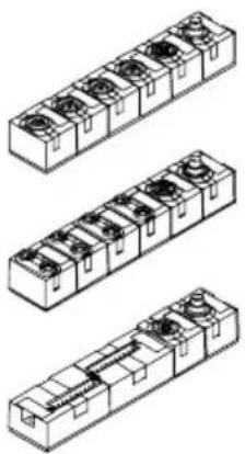 | Input modules PNP:– C P-E08-M12-CL:8 digital inputs,4 M12 sockets, 5-pin– C P-E08-M8-CL:8 digital inputs,8 M8 sockets, 3-pin– C P-E16-KL-CL:16 digital inputs,2 series plugs, 10-pin |
 | Output modules PNP:– C P-A04-M12-CL4 digital outputs,4 M12 sockets, 5-pin |
Tab. 0/1: CP I/O modules type CP-...-CL
Input module type CP-E16-KL-CL offers 2 series plugs for screw terminal sockets or tension spring sockets (see section A.6.4).
| Thismanualrefersto: | |
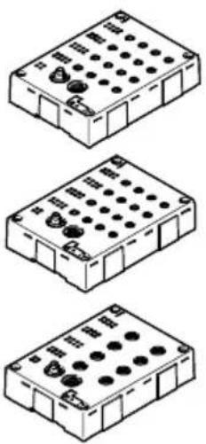 | Input modules PNP:- CP-E32-M8-EL:32 digital inputs,16 M8 sockets, 4-pin- CP-E16-M8-EL:16 digital inputs,16 M8 sockets, 3-pin- CP-E16-M12-EL:16 digital inputs,8 M12 sockets, 5-pin |
 | Output modules PNP:- CP-A08-M12-EL-Z8 digital outputs,8 M12 sockets, 5-pin |
Tab. 0/2: CP I/O modules type CP-...-EL
Basic information, which must be observed in conjunction with the CPI/CP master, can be found in the manuals for the relevant CPI/CP master and in the CPI system description for typeCPX-CP-....
| TypeTitleDescription | ||
| CPIsystem, Description electronics | “CPsystem” TypeP.BE-CPX-CP-...  | General basic information on fitting, installing and commissioning CPI systems and on their method of operation. |
| Moduleswith CPconnection, descriptionof electronics | “CPVDirect” TypeP.BE-CP-DI...  | Instructions on fitting, installing, commissioning and diagnosing the relevant CPV valve terminal withdirectconnection. |
“CPfieldbusnode” TypeP.BE-CPX-FB.../ CP-4-FB-...  | Instructions on fitting, installing, commissioning and diagnosing the relevant fieldbus node. | |
“CDVI...” TypeP.BE-CDVI-DN-...  | Instructions on fitting, installing, commissioning and diagnosing the relevant CDVI with fieldbus directconnection“DeviceNet.” | |
“CPA-SC/CPV-SC...” TypeP.BE-CPASC- CPVSC-...  | Instructions on fitting, installing, commissioning and diagnosing the CPV-SC or CPA-SC valve terminal with fieldbus direct connection for PROFIBUSDPorDeviceNet. | |
| CPmodules, descriptionof electronics | “CPmodules” TypeP.BE-CPEA-...  | Information on fitting, installing and commission-ingCPI/Omodules. |
| Valve terminals, Pneumatics manual | “Valveterminalswith CPVpneumatics” TypeP.BE-CPV-...  | Information on fitting, installing and commission-ing CPV valve terminals (type 10). |
“Valveterminalswith MPApneumatics” TypeP.BE-MPA-...  | Information on fitting, installing and commissioning MPA valve terminals (type 32), (type33). | |
“Valveterminalswith CPApneumatics” TypeP.BE-CPA-...  | Information on fitting, installing and commission-ing CPA valve terminals (type 12). | |
Tab. 0/3: ManualsontheCPI/CPsystem
The following product-specific terms and abbreviations are used in this manual:
| Term/abbreviation | Meaning |
| ADigitaloutput | |
| CPcableSpecialcableforo | connectingthevariousCPI/CPmodulesinaCPstring.Colour:black,typeKVI-CP1-...andtypeKVI-CP2-... |
| CP functions | Supports the CP protocolwithoutextended functions |
| CPmodule/valve terminal | CommontermformoduleswithoutextendedfunctionswhichcanbeincorporatedinaCPI/CPsystem. |
| CPstringCPIorCPmodules | whichareconnectedbyCPI/CPcableandwhichareconnectedtotheCPX-CPinterface.Forreasonsofsimplicity,onlytheterm “CPstring”isused,evenifithasCPIfunctionality. |
| CPsystemCompleteelectricalinstallationsystemconsistingofaCPmasterwithoneormoreCPstrings.ThesystemconsistsofCPmodules(withoutextended functions). | |
| CPIcableSpecialcablefor | connectingthevariousCPI/CPmodulesinaCPstring.Colour:white,typeKVI-CP3-... |
| CPIconnectionSocketorplugontheCPImoduleswhichallowsthemodulestobeconnectedusingtheCPIorCPcable. | |
| CPIfieldbusinterfaceTermforaCPIcapableinterfacewithfieldbusconnection(e.g.combination ofCPXfieldbusnodeandCPX-CPinterface(CPIfieldbusmodule)orCPV withCPIstringextension(CPVDirect)) | |
| CPIfieldbusmoduleDefinedcombinationofaCPXfieldbusnodeandaCPX-CPinterface.ConnectsaCPIsystemwithafieldbus. | |
| CPI functions | Supports the CPI protocolwithextended functions |
| CPImodule/valve terminal | CommontermformoduleswithextendedfunctionswhichcanbeincorporatedinaCPI/CPsystem. |
| CPIsystem | Also:“CPIinstallationsystem”CompleteelectricalinstallationsystemconsistingofaCPmasterwithone or more CP strings. The system consists of CPI/CP moduleswithandwithoutextendedfunctions.ThesystemneednotconsistexclusivelyofCPI modules. |
| E | Digitalinput |
| Inputmodule | Inputmodule |
| Term/abbreviationMeaning | |
| I/OsDigitalinputsandoutputs | |
| I/OmodulesCollectivetermforthemoduleswhichprovideddigitalinputsandoutputs(e.g.,CPXI/Omodules,CPIinputmodulesandCPIoutputmodules). | |
| OutputmoduleOutputmodule | |
| StringallocationTypeandorderoftheCPI/CPmodulesconnectedtooneormoreCPstrings. | |
Tab. 0/4:Specifictermsandabbreviations
SystemoverviewCPI/CPsystem
Chapter1
- Systemoverview CPI/CP system
Contents
1. System overview CPI/CP system 1-1
1.1SettingupCPIsystems1-3......
1.1.1MethodofoperationoftheCPI/CPsystem1-5......
1.1.2 Rules for extending the CPI system 1-8
1.1.3Useofthel/Omodules ..... 1-11
1.1.4 Basic rules for addressing 1-13
- SystemoverviewCPI/CPsystem
1.1SettingupCPIsystems
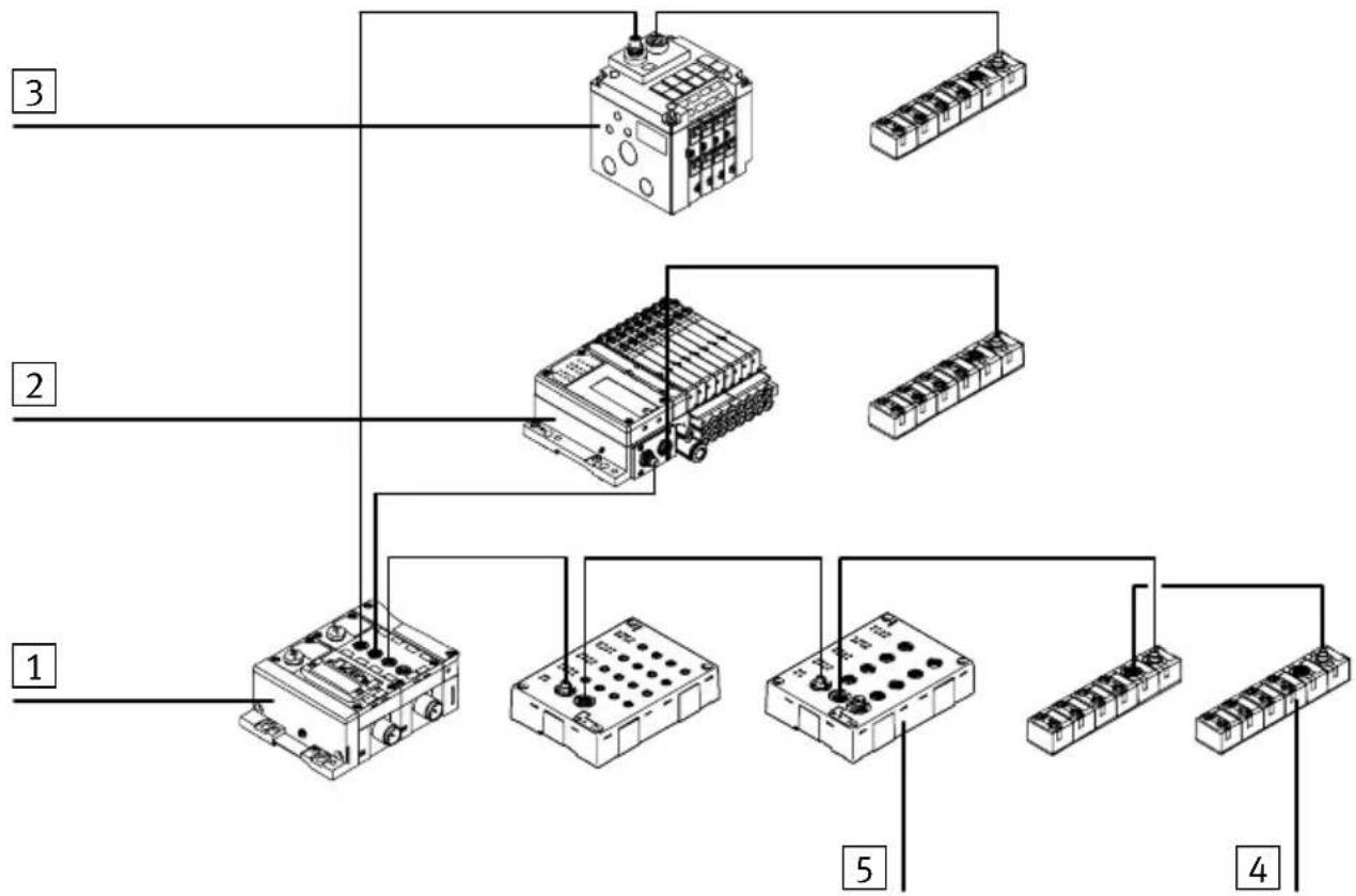
Festocanassistyouinsolvingyourautomationtaskat themachinelevelwiththeaidofvalveterminals.Dueto theirmodularstructure,theCPvalveterminalsfromFesto willenableyoutoincludevalveterminalsandI/Omodules optimallyinyourmachinesandsystems.
flowchart
graph TD
    A["1"] --> B["2"]
    B --> C["3"]
    A --> D["4"]
    A --> E["5"]
    B --> F["6"]
    B --> G["7"]
    C --> H["8"]
    C --> I["9"]
    D --> J["10"]
    D --> K["11"]
    E --> L["12"]
    E --> M["13"]
    F --> N["14"]
    F --> O["15"]
    G --> P["16"]
    G --> Q["17"]
    H --> R["18"]
    H --> S["19"]
    I --> T["20"]
    I --> U["21"]
    J --> V["22"]
    J --> W["23"]
1 CPIfieldbusnode
2 MPA-CPIvalveterminal
3 CPV-CPIvalveterminal
4 CP-CLmodule
5 CP-ELmodule
Fig. 1/1:Example:SettingupaCPIsystem
TheCPI/CPsystemconsistsofindividualmoduleswhichare connectedtoeachotherbymeansofCPcables.Inthiswayit ispossibletodecentralizethearrangementoftheCPsystem. ThecompactCPvalveterminalscanbemountedverycloseto thecylinderstobecontrolled.Thisenablesshortcompressed air tubingtobeused.
Systemlossescanbeminimizedifshortcompressedair tubingisusedandthetimesrequiredforpressurisingand exhaustingthetubingcanbereduced.
Thisenablessmallervalveswithsufficientflowtobeused, therebyhelpingtoreducecosts.
1.1.1 Method of operation of the CPI/CP system
CPI/CPsystemsarecomposedofthefollowingmodules:
| Modules | Function |
 | CPfieldbusnodesandCPmodules areavailableforthevariousfieldbuses.-Theseprovidetheconnectiontocertain fieldbuses.-Theseofferconnectionsforuptofour stringstowwhichl/OmodulesandCP valveterminalsareconnected.-Theytransmitcontrolsignalstothecn- nectedmodulesandmonitortheirfunc- tioning. |
CPV/CPV-SCvalve terminalswithCPI connection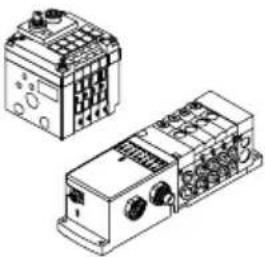 | -Theseprovidedifferentvalvefunctions viavalveplatesforcontrollingpneu- maticactuators.-Relayplates,pressurezoneseparation platesandblankingplatescanalsobe fitted. |
| ModulesFunction | |
MPAvalveterminal withCPIconnection | -Theseprovidedifferentvalvefunctions via valves for controlling pneumatic actuators. |
Inputmodules (typeCL,EL,RL)   | -Theseprovide inputs for connecting sensors and enablee.g. cylinder positionstobescanned. |
Outputmodules (typeCL,EL,RL) [WG7Δ1] [WG7Δ1] | -These provide universalelectric outputs for controlling low-current consuming devices (further valves, bulbs etc.). |
Tab. 1/1:OverviewoftheCPImodules
1. SystemoverviewCPI/CPsystem
Dependingontheirdesign,CPI/CPmasterscontrolthe transferofdatatothedifferentcontrolsystemsviathe variousfieldbuses.
1 Fieldbus (incoming)
2 Fieldbus (continuing)
3 CPImaster(here CPX-CPinterface)
4 CPvalveterminal
5 CPIinput moduleEL
6 Sensor
7 Cylinders
8CPlinput moduleCL
9 CPIoutput moduleEL
10CPloutput moduleCL

flowchart
graph TD
    A["Component 1"] --> B["Switch 1"]
    C["Component 2"] --> B
    D["Component 3"] --> B
    E["Component 4"] --> F["Relays 1-6"]
    G["Component 5"] --> H["Relays 7-10"]
    I["Component 6"] --> J["Relays 8-9"]
    K["Component 7"] --> L["Relays 9-10"]
    M["Component 8"] --> N["Relays 6-7"]
    O["Component 9"] --> P["Relays 10"]
Fig. 1/2: Method of operation of the CP system
1.1.2 RulesforextendingtheCPIsystem
TheCPIsystemsupportsadifferentnumberofmodulesper CPstring,dependingonthetypeofCPmasterandonthe CPI/CPmodulesconnected.
TheCPVDirectisaCPImaster.
Modulescanbeplacedintwodifferentgroups:
-CPImodules(withextendedfunctions)
- C P modules(withoutextendedfunctions)
| Rulesandproperties | |
| CPIsystem-Max.4m | modulesontheCPstring-Max.32inputsand32outputs(perCPstring)-ThesequenceofthemoduleswithintheCPstringisoptional |
| CPImasterAmixture | ofCPI/CPmodulesispossibleonCPImasters:-OnlyoneCPinputmoduleispossibleattheendofastring-OnlyoneCPvalveterminal 2)oroneCPoutputmodule 2)ispossibleperCP string-“Unused”locationsontheCPstringcanbe“filled”withCPImodules 1) |
| CPI modules | Modules always have an incoming and continuing interface on all CPI modules (inputmodules,outputmodules)andvalveterminalswithCPIconnection |
| 1)withextendedfunctions2)withoutextendedfunctions | |
Tab. 1/2: RulesforextendingtheCPIsystem

Note
IrrespectiveofthetypeofCPI/CPmodules, notmorethan 32inputsand32outputsmaybeconnected(sumofall modulesonaCPstring).
ThismeansthataCPstringcanbeextendedbymaximum2CPvalveterminalswithCPIability,asCPvalveterminalsalwaysoccupy16outputaddresses.
1. SystemoverviewCPI/CPsystem

flowchart
graph TD
    A["CPImaster"] --> B["CP(O)CPI(I/O)"]
    A --> C["CPI(I/O)CPI(I/O)"]
    A --> D["CPI(I/O)"]
    B --> E["CPI(I/O)"]
    B --> F["CP(O)"]
    C --> G["CPI(I/O)"]
    C --> H["CPI(I/O)"]
    D --> I["CPI(I/O)"]
    D --> J["CPI(I/O)"]
    E --> K["CPI(I/O)"]
    E --> L["CPI(I/O)"]
    F --> M["CPI(I/O)"]
    F --> N["CPI(I/O)"]
    G --> O["CPI(I/O)"]
    G --> P["CPI(I/O)CPI(I/O)"]
    H --> Q["CPI(I/O)"]
    H --> R["CPI(I/O)"]
    I --> S["CPI(I/O)"]
    I --> T["CPI(I/O)"]
    J --> U["CPI(I/O)"]
    J --> V["CPI(I/O)"]
    K --> W["CPI(I/O)"]
    K --> X["CPI(I/O)"]
    L --> Y["CPI(I/O)"]
    L --> Z["CPI(I/O)"]
    M --> AA["CPI(I/O)"]
    M --> AB["CPI(I/O)"]
    N --> AC["CPI(I/O)"]
    N --> AD["CPI(I/O)"]
    O --> AE["CPI(I/O)"]
    O --> AF["CPI(I/O)"]
    P --> AG["CPI(I/O)"]
    P --> AH["CPI(I/O)"]
    Q --> AI["CPI(I/CPI(O))"]
    R --> AJ["CPI(I/CPI(O))"]
    S --> AK["CPI(I/CPI(O))"]
    T --> AL["CPI(I/CPI(O))"]
    U --> AM["CPI(I/CPI(O))"]
    V --> AN["CPI(I/CPI(O))"]
    W --> AO["CPI(I/CPI(O))"]
    X --> AP["CPI(I/CPI(O))"]
    Y --> AQ["CPI(I/CPI(O))"]
    Z --> AR["CPI(I/CPI(O))"]
    AA --> AS["CPI(I/CPI(O))"]
    AB --> AT["CPI(I/CPI(O))"]
    AC --> AU["CPI(I/CPI(O))"]
    AD --> AV["CPI(I/CPI(O))"]
    AE --> AW["CPI(I/CPI(O))"]
    AF --> AX["CPI(I/CPI(O))"]
    AG --> AY["CPI(I/CPI(O))"]
    AH --> AZ["CPI(I/CPI(O))"]
    AI --> BA["CPI(I/CPI(O))"]
    AJ --> BB["CPI(I/CPI(O))"]
    AK --> BC["CPI(I/CPI(O))"]
    AL --> BD["CPI(I/CPI(O))"]
    AM --> BE["CPI(I/CPI(O))"]
    AN --> BF["CPI(I/CPI(O))"]
    AO --> BG["CPI(I/CPI(O))"]
    AP --> BH["CPI(I/CPI(O))"]
    AQ --> BI["CPI(I/CPI(O))"]
    AR --> BJ["CPI(I/CPI(O))"]
grey:CPI(withextendedfunctions)
CP(I):CPinputmodule
CP(O):CPoutputmoduleorCPvalveterminal
CPI(I/O): CPIinputoroutputmodule(withextendedfunctions) or CPvalveterminal with CPIability (forvalveterminal: max.2 possible)
Rules:
CP:TherulesfortheCPmasterremainvalid.
CPI:Max.32inputsand32outputsperstring,max.4modulesperstring
Max.1CPoutputmoduleor1CPvalveterminal
Max.1CInputmodulealwaysattheendofthestring
Max.2valveterminalswithCPIfunctionsperstring
Fig. 1/3: ExpansionofaCPI/CPsystem
The followinglistofCPI/CPmoduleshowsineachcasetheir functionsaswellasthemaximumpossiblenumberofinputs oroutputsoneachCPI/CPmodule.
| CPI/CPmodules\nTypeTypeModule | supports extended functions | AssignedI/Os | ||||
| onCPmasters withextended functions | onCPmasters withoutex-tendedfunctions | |||||
| EAEA | ||||||
| CPI/CPinput modules | CP-E08-M8-CL | Yes | 8 E | - | 16E | - |
| CP-E08-M12-CL | Yes | 8 E | - | 16E | - | |
| CP-E16-KL-CL | Yes | 16E | - | 16E | - | |
| CP-E16-M12-EL | Yes | 16E | - | 16E | - | |
| CP-E16-M8-EL | Yes | 16E | - | 16E | - | |
| CP-E32-M8-EL | Yes | 32E | - | -1) | -1) | |
| CP-E16-M8 | No | 16E | - | 16E | - | |
| CP-E16N-M8 | No | 16E | - | 16E | - | |
| CP-E16-M8-Z | No | 16E | - | 16E | - | |
| CP-E16-M12x2-5POL | No | 16E | - | 16E | - | |
| CP-E16N-M12x2 | No | 16E | - | 16E | - | |
| CP-E16-KL-IP20-Z | No | 16E | - | 16E | - | |
| CPI/CPoutput modules | CP-A04-M12-CL | Yes | - | 8 A | - | 16A |
| CP-A08-M12-EL-Z | Yes | - | 8 A | - | 16A | |
| CP-A08-M12-5POL | No | - | 16A | - | 16A | |
| CP-A08N-M12 | No | - | 16A | - | 16A | |
| 1)NofunctiononCPmaster | ||||||
Tab. 1/3: AssignedI/OsoftheCPI/CPmodules
1. Systemoverview CPI/CP system
1.1.3 Useofthel/Omodules
CPI/CPI/Omodulescanbeusedinconjunctionwithvarious CPI/CPmasters.Thesearee.g.:
-CPXterminalwithCPX-CPinterface
- C P fieldbusnode
-CPVDirect
-CPV-SC-DN/CPA-SC-DN
-CPV-SC-DP/CPA-SC-DP
-CDVI-DN
TheCPI/CPmastersaredistinguishedbythedifferent numberofCPstringsmadeavailable,bythefunctions,the maximumnumberofinputsandoutputs tobeprocessedand thenumberofCPI/CPmodulesperstring.
| CPI/CPmastertypeNumberofstrings | FunctionalityMax.numberofinputs/outputperstring | Max.numberofmodulesperstring |
| CPXwithCPinterface4CP16I+16O24CPI(advanced) 1) | 32I+32O4 | |
| CPfieldbusnode4CP16I+16O2 | ||
| CPVDirect1CP16I+16O21CPI(advanced) 1) | 32I+32O 1) | 4 1) |
| CPV-SC-DP/CPA-SC-DP1CP16I+16O21CPI(advanced) 1) | 32I+32O 1) | 4 1) |
| CPV-SC-DN/CPA-SC-DN1CP16I+16O21CPI(advanced) 1) | 32I+32O 1) | 4 1) |
| CDVI-DN1CP16I+16O2 | ||
| 1)SupportingtheextendedfunctionswithCPV-DI02,CPV-CS02,CPV-DI02,CS02,DN3,CO3. | ||
Tab. 1/4: Overview, CPI/CPmaster
ThecompactCPI/CPI/Omodules(typeCP-...-CLand-EL) described in this manuals support the extended functions of the CPI system. Combinations with other CPI/CP modules are possible, but limit the number of CPI/CP modules per string. The limitations described in section 1.2 apply.

Note
CPII/Omoduleswithextendedfunctions,e.g.type CP-...-CL,-ELcanalsobeoperatedonCPmasterswithout extendedfunctions(seeTab. 1/3).
1. Systemoverview CPI/CP system
1.1.4 Basicrulesforaddressing
Addressingdependson:
-CPI/CPmasterused
–Thefieldbusprotocolused
The following rules apply:
-AddressingiscarriedoutinascendingorderofconnectionbeginningontheCPmaster.
- In the case of CP masters without extended functions, each CPI/CP module occupies 16 inputs or 16 outputs, irrespective of the design.
- In the case of masters with extended functions, the following difference applies:
-Moduleswithoutextendedfunctionsusuallyoccupy 16inputsor16outputs.
-Dependingonthetype, moduleswithextendedfunctionsoccupy8...32inputsor8...32outputs.

Note
Furtherinformationonaddressingcanbefoundinthe relevantmanualsfortheCPmasters.
- SystemoverviewCPI/CPsystem
InputmoduletypesCP-E08-M...-CLand CP-E16-KL-CL
Chapter2
2.InputmoduletypesCP-E08-M...-CLandCP-E16-KL-CL
Contents
2.InputmoduletypesCP-E08-M...-CLandCP-E16-KL-CL2-1.....
2.1 FunctionoftheinputmodulesCP-E08-M...-CLandCP-E16-KL-CL2-3.....
2.1.1 Display and connecting elements 2-4.....
2.2Mounting2-7....
2.3 Installation 2-8
2.3.1 Connecting sensors 2-9
2.3.2 Connect the input module to the CP string 2-12
2.4Diagnosis .... 2-14
2.4.1 Diagnosis via LEDs . 2-14
2.4.2 Diagnosis via the field bus 2-17
2.1FunctionoftheinputmodulesCP-E08-M...-CLandCP-E16-KL-CL
CPinputmodulesprovideddigitalinputsforconnectingsensors,therebyenablinge.g. cylinderpositionstobescanned. Adistinctionismadebetweenthefollowingtypes:
| Product illustration | TypeExplanation | |
| Sensorconnectionsvia4socketswithM12thread,5-pin | ||
 | CP-E08-M12-CLProvides8PNInputs(IP65/IP67). | |
| Sensorconnectionsvia8socketswithM8thread,3-pin | ||
 | CP-E08-M8-CLProvides8PNInputs(IP65/IP67). | |
| Sensorconnectionsvia2seriesplugs,10-pinandconnectorsocketsineitherscrewortensionspring design. | ||
 | CP-E16-KL-CLProvides16PNInputs.Especiallysuitableforfittingintoacontrolcabinet (IP20). | |
Tab. 2/1:Overviewofinputmodules
2.1.1 Display and connecting elements
The following diagram show the display and connecting elementsofinput module CP-E08-M12-CL.

Fig. 2/1: Display and connecting element type CP-E08-M12-CL
The following diagram show sthedisplay and connecting elementsofinputmoduleCP-E08-M8-CL.

Fig. 2/2: Display and connecting element type CP-E08-M8-CL
The following diagram show sthedisplay and connecting elementsofinputmoduleCP-E16-KL-CL.
1 CPconnection incoming
2 ContinuingCP connection
3 StatusLEDshort circuit/overload/undervoltagein sensorsupply(red)
4 StatusLEDCP communication (PS, green)
5 Nameplate
6 Mountinghole
7 Grooveforidentificationsigns(4x)(type IBS8x20)
8 Sensorconnections (8inputsperplug)
9 Fasteningholewith earthconnection

Fig. 2/3: Display and connecting element type CP-E16-KL-CL
2.2Mounting
Theinputmodulesareintendedforfittingontoawalloronto profiles.Takeintoaccountthefollowingdimensionsand weights:
| Type | DimensionsWeight | |
| CP-E08-M12-CLapprox. | 151x30x34.5mmapprox.165g | |
| CP-E08-M8-CLapprox. | 151x30x34.5mmapprox.190g | |
| CP-E16-KL-CLapprox. | 151x30x34.5mmapprox.145g |
Tab. 2/2:Dimensionsoftheinputmodule
FittingontoawallThefollowingdiagramshowsthedimensionsfortheholesof screwsizeM4.Alwaysfasteneachmodulewith2screwsand alockingdisc.
Tighteningtorqueofthefasteningscrews:2±0.5Nm.

Fig. 2/4: FittingdimensionsCP-E...-CL
Tip: Thepositionofthefasteningscrewsonclipped-indrawing platesismarkedwiththesymbol ☐.
2.3 Installation

Warning
Suddenunexpectedmovementsoftheconnectedactuatorsandundefinedswitchingstatesoftheelectroniscan causeinjurytohumanbeingsanddamagetoproperty.
Beforecarryingoutinstallationandmaintenancework, switchoffthefollowing:
-theoperatingandloadvoltagesupplyontheCPmaster (e.g. CPI/CPfieldbusnode)
-separatepowersupplies

Warning
Incorrectormissingearthingmeasurescancauseinterferenceduetoelectromagneticinfluences.
Connecttheearthingcableonthehousing(screwunder typeplate,see Fig. 2/1, Fig. 2/2 or Fig. 2/3)atlowimpedance(shortcablewithlargediameter)totheearthpotential.
Asuitablecableclipissuppliedwiththemodule.
2.3.1 Connecting sensors

Caution
Longsignalcablesreducetheimmunitytointerference. Donotexceedthemaximumpermittedsignalcablelength of30m.

UseplugsandcablesfromtheFestorange(seeAppendix A.6)forconnecting sensors.
InthecaseofCPinputmodulestypeCP-E08-M12-CLand CP-E08-M8-CL:
- Tightentheplugswiththeaidoftheunionnutinorderto preventunintentionalloosening,e.g.duetoshock.
- Seal unused connections with protective caps. Only in this way can you comply with protection class IP 65/IP67. Use protective caps from the Festo range (see Appendix A.6).
WithCPinputmoduletypeCP-E16-KL-CL:

Furtherinformationonconnectorsetsaswellasinstructions onhandlingthemcanbefoundinAppendixA.6.4.
Pinassignment(PNInputs)
The following diagramsshowasanexamplethepinassignmentofthesensorconnectionsofthedifferentCPinput modules.
Pinassignment
1 1:24 V
2: |x+1
3:0 V
4:1x+0
5:Groundterminal
lx=Inputx
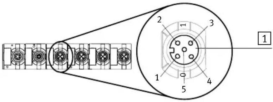
Fig. 2/5: PinassignmenttypeCP-E08-M12-CL
Pinassignment
1 1:24 V
4: |x+1
3:0 V
2 1:24 V
4:1x+0
3:0 V
Ix=Inputx
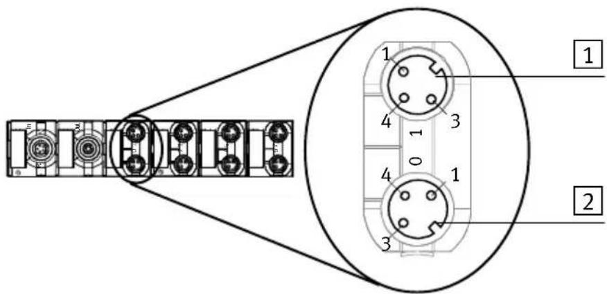
Fig. 2/6: PinassignmenttypeCP-E08-M8-CL
WithinputmoduletypeCP-E16-KL-CL,eightsensorscanbe connectedtoconnectionsX1andX2.Thevoltagesuppliedvia theCPstringisprovidedattheterminals+and-ofX1andX2 forsupplyingthesensors.

Caution
Donotconnectanexternalsupplytotheterminals+and-ofX1andX2. Otherwisetheinputmodulewillbedamaged.
Pinassignment
1 PlugX1
-:0VDC
7:lx+7
6:lx+6
...
2:lx+2
1:lx+1
0:ix+0
+:24VDC
2 PlugX2
-:0VDC
7:lx+15
6:lx+14
...
2:lx+10
1:lx+9
0:lx+8
+:24VDC

Ix=Inputx
Fig. 2/7: PinassignmentofplugsX1andX2ontypeCP-E16-KL-CL
Usespringtensionplugsorscrewconnectorplugsfromthe Festorange(seeAppendixA.6.4)forconnecting sensors.
2.3.2 ConnecttheinputmoduletotheCPstring

Caution
FaultindatatransferontheCPstring.
Notethemaximumpermittedstringlengthsinthemanual fortheCPmasterused.
Youwillthenavoidfaultsindatatransferbetweenthe inputmoduleandtheCPmaster(e. g.CPfieldbusnode).

Caution
Functionaldamage
Notethemaximumpermittedstringlengthsinthemanual fortheCPmasterused.
UseonlytheintendedoriginalcabletypeKVI-CP-...fromFesto forconnectingtheCPI/CPmodules,seemanualfortheCP masterused.

Note
Specificationsonthecurrentconsumptionofthedifferent CPI/CPmodulescanbefoundintherelevantmanuals.
The following functions are provided for the module via the CPcable:
-Operatingvoltageforinternalelectronics
-Connectionfordataexchange
-Operatingvoltagefortheconnectedsensors
TheCPImodulesareconnectedsequentially.TheM9plugis theincominginterface;theM9socketisthecontinuedinterface(see Fig. 2/1 to Fig. 2/3).
If the continuing CP connection is not used:
- SealtheCPconnectionwithaprotectivecaptype FLANSCHDOSESER.712, partno.356684 (accessories). Onlyinthiswaycanyoucomplywithprotectionclass IP65/IP67.

Note
The continuing CP connection can only be used in conjunction with a CP master with extended functions.
2.InputmoduletypesCP-E08-M...-CLandCP-E16-KL-CL
2.4Diagnosis
2.4.1 Diagnosis via LEDs
StatusLED
CPcommunication(PS)
Theoperatingstatusoftheinputmoduleisshownbymeans ofthestatusLEDCPcommunication(seeTab. 2/3).
| LEDPS(green) | OperatingstatusErrorhandling | |
 LEDlightsup LEDlightsup | Operatingvoltageapplied,CP communicationOK | None |
 LEDisout LEDisout | -Operatingvoltagenotap- pliedornoconnectionto CPI/CPmaster-CPI/CPinputmodulenot containedinstringassign- mentoftheCPI/CPmaster | •ChecktheCPI/CPcableandtheoperating voltageconnectionontheCPmaster•SavetheCPI/CPstringassignmentonthe CPI/CPmaster(seemanualfortheCPI/CP master) |
 LEDflashes LEDflashes | -Testphasewhenpowersup- plyhasbeenswitchedon 1)or-Undervoltageinsensorsup- ply(<17V) | •Noneor•Eliminateundervoltage |
| 1) OnlyonCPmasterswithoutextendedfunctions | ||
Tab. 2/3: StatusLEDCPcommunication(PS)
StatusLED
Shortcircuit/overload
Shortcircuitoroverloadofthesensorsupplyisshownby meansofthestatusLEDshortcircuit/overload(see
Tab. 2/4).
| LED(hed) | OperatingstatusErrorhandling | |
 LEDisout LEDisout | - N o shortcircuit/overloadin sensorsupply | •None |
 LEDlightsup LEDlightsup | -Shortcircuit/overloadin sensorsupply | •Removeshortcircuitand,ifapplicable,deleteerror |
Tab. 2/4: StatusLEDshortcircuit/overload
Reactiontoshortcircuitinthesensorsupply
If thereisashortcircuit, the input module will switch off the powersupply to the sensors and communicate the fault to the CP master. The status LED will be switched off and the input of the modules supply a0-signal.
StatusLEDs
Statusdisplayforinput
OnlywithtypesCP-E08-M12-CLandCP-E08-M8-CL:
NexttothesensorconnectionsthereisagreenLEDfor everyinput. Thisshowsthestatusofthesignalatthe relevantinput.
| LEDstatusof input | Status |
 | Logical1(signalpresent) |
| LEDlightsup | |
 | Logical0(nosignal) |
| LEDisout |
Tab. 2/5: StatusLEDsforstatusdisplayofinput
2.4.2 Diagnosis viathefieldbus
Depending on the CPI/CP master used, the CP module type CP-...-EL provided different diagnostic information on fault searching.
| Master | Diagnosisofshort circuit/overloadin sensorsupply | Diagnostics, undervoltage,sensorsupply |
| CPmaster (withoutextended functions) | YesNo | |
| CPImaster (withextended functions) | YesYes |
Tab. 2/6: Diagnostic information

Note
Instructionsonevaluatingthediagnosticmessagecanbe foundinthemanualfortherelevantCPI/CPmaster.
2.InputmoduletypesCP-E08-M...-CLandCP-E16-KL-CL
OutputmoduletypeCP-A04-M12-CL
Chapter3
Contents
3. Output module type CP-A04-M12-CL 3-1
3.1FunctionofoutputmoduletypeCP-A04-M12-CL3-3......
3.1.1 Display and connecting elements 3-4
3.2Mounting3-5
3.3Installation .. 3-6
3.3.1 Connecting the actuators 3-7
3.3.2 Connect the output module to the CP string 3-8
3.4 Diagnostics 3-10
3.4.1 Diagnostics via LEDs 3-10
3.4.2 Diagnostics via the fieldbus 3-13
3.1 FunctionofoutputmoduletypeCP-A04-M12-CL
OutputmoduletypeCP-A04-M12-CLprovides4universally-usabledigitaloutputsforcontrollinglow-currentconsuming devices(e.g.bulbs,furthervalves,etc.).
| Product illustration | TypeExplanation | |
| Actuatorconnectionsvia4socketswithM12thread | ||
 | CP-A04-M12-CLProvides4PNPoutputs(IP65/IP67). | |
Tab. 3/1:Overviewofoutputmodules
3.1.1 Display and connecting elements
Thediagrambelowshowsthedisplayandconnecting elementsontheoutputmodules.
1 CPconnection incoming
2 ContinuingCP connection
3 StatusLEDload supply(PL, green)
4 StatusLEDsforout-puts(statusdisplay, yellow)
5 StatusLEDshort circuit/overloadat outputs(red)
6 StatusLEDCP communication (PS, green)
7 Actuatorconnections
8 Nameplate
9 Grooveforidentificationsigns,6x(type IBS8x20)
10Mountinghole
11 Fasteningholewith earthconnection

Fig. 3/1: Display and connecting element type CP-A04-M12-CL
3.2Mounting
Theoutputmoduleisintendedforfittingontoawalloronto profiles.Takeintoaccountthefollowingdimensionsand weights:
| Type | DimensionsWeight | |
| CP-A04-M12-CLapprox. | 151x30x34.5mmapprox. | 165g |
Tab. 3/2:Dimensionsofoutputmodule
FittingontoawallThefollowingdiagramshowsthedimensionsfortheholesof screwsizeM4.Alwaysfasteneachmodulewith2screwsand alockingdisc. Tighteningtorqueofthefasteningscrews: 2 ± 0.5 Nm .

Fig. 3/2: FittingdimensionsCP-A04-M12-CL
Tip: Thepositionofthefasteningscrewsonclipped-indrawing platesismarkedwiththesymbol ∅.
3.3 Installation

Warning
Suddenunexpectedmovementsoftheconnectedactuatorsandundefinedswitchingstatesoftheelectroniscan causeinjurytohumanbeingsanddamagetoproperty.
Beforecarryingoutinstallationandmaintenancework, switchoffthefollowing:
–The operating and load voltages supply on the CP master (e.g. CPI/CP field bus node)
–Separatepowersupplies

Warning
Incorrectormissingearthingmeasurescancauseinterferenceduetoelectromagneticinfluences.
Connecttheearthingcableonthehousing(screwunder typeplate,see Fig. 3/1)atlowimpedance(shortcable withlargediameter)totheearthpotential.
(Asuitablecableclipissuppliedwiththemodule.)
3.3.1 Connectingtheactuators

Forconnectingtheactuators,useplugsandcableswithunion nutandM12threadfromtheFestorange(seeAppendixA.6)
- Tightentheplugswiththeaidoftheunionnutinorderto preventunintentionalloosening, e.g. duetoshock.
- Sealunusedconnectionswiththeprotectivecapssupplied.Onlyinthiswaycanyoucomplywithprotection classIP65/IP67.
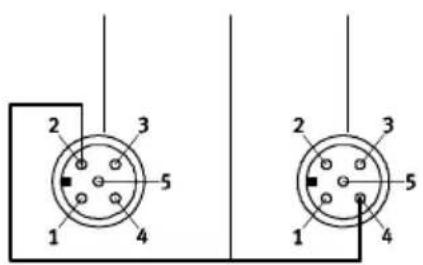
Pinallocation
The following diagram shows as an example the pin allocation of the actuator connections on the CPI/CP output module.
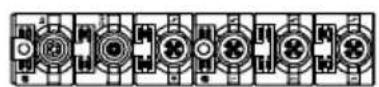

Port1Port2Port3Port4
1 Pinallocation Connection1
1: n.c.
2: Ax+1
3:0V
4: Ax+0
5: FE
2 Pinallocation Connection2
3 Pinallocation Connection3
1: n.c.
2: Ax+3
3:0V
4: Ax+2
5: FE
4 Pinallocation Connection4
1: n.c.
2: n.c.
3:0V
4: Ax+3
5: FE
5 Internal connection in module
n.c. = (not connected)
AX = outputx
Fig. 3/3: PinallocationtypeCP-A04-M12-CL

Note
Whenswitchinginductiveloads, besuretouseasuitable safetycircuit(e.g.free-whilingdiode).
3.3.2ConnecttheoutputmoduletotheCPstring

Caution
FaultindatatransferontheCPI/CPstring.
Notethemaximumpermittedstringlengthsinthemanual fortheCPImasterused.
Youwillthenavoidfaultsindatatransferbetween the inputmoduleandtheCPmaster(e.g. CPfieldbusnode).

Caution
Functionaldamage
Notethemaximumpermittedstringlengthsinthemanual fortheCPImasterused.
UseonlytheintendedoriginalcabletypeKVI-CP-...fromFesto forconnectingtheCPI/CPmodules,seemanualfortheCPI masterused.

Note
Specificationsonthecurrentconsumptionofthedifferent CPI/CPmodulescanbefoundintherelevantmanuals.
The following functions are provided for the module via the CPI/CP cable:
-Operatingvoltageforinternalelectronics
-Connectionfordataexchange
-Operating voltage for the connected actuators
TheCPImodulesareconnectedsequentially.TheM9plugis theincominginterface;theM9socketisthecontinuedinterface(seeFig. 3/1).
If the continuing CP connection is not used:
- SealtheCPconnectionwithaprotectivecaptype FLANSCHDOSESER.712, partno.356684(accessories). Onlyinthiswaycanyoucomplywithprotectionclass IP65/IP67.

Note
CheckwithintheframeworkofyourEMERGENCYSTOP circuit,toascertainthemeasuresnecessaryforputting yourmachine/systemintoasafestateintheeventofan EMERGENCYSTOP(e.g.switchingofftheoperatingvoltage forthevalvesandoutputmodules,switchingoffthecompressedair).
3.4 Diagnostics
3.4.1 DiagnosticsviaLEDs
StatusLED
CPcommunication(PS)
Theoperatingstatusoftheoutputmoduleisshownby
meansofthestatusLEDCPcommunication(seeTab.3/3).
| LEDPS(green) | OperatingstatusErrorhandling | |
 LEDlightsup LEDlightsup | Operatingvoltageapplied,CPI/CPcommunicationOK | None |
| [Y60Z]LEDisout | -Operatingvoltagenotap-pliedornoconnectiontoCPI/CPmaster-CPI/CPoutputmodulenot containedinstringallocation oftheCPI/CPmaster | •ChecktheCPI/CPcableandtheoperating voltageconnectionontheCPI/CPmaster•SavetheCPI/CPstringallocationontheCPI/CPmaster(seemanualfortheCPI/CP master) |
 LEDflashes LEDflashes | -Testphasewhenthepower supplyhasbeenswitched on 1) | •None |
| 1) OnlyonCPImasterswithoutextendedfunctions | ||
Tab. 3/3: StatusLEDCPcommunication(PS)
StatusLED Loadsupply(PL)
Shortcircuitoroverloadoftheactuatorsupplyisshownby meansofthestatusLEDshortcircuit/overload(see Tab. 3/4).
| LEDPL(green) | OperatingstatusErrorhandling | |
 LEDlightsup LEDlightsup | LoadsupplyOKNone | |
 LEDflashes LEDflashes | -Undervoltageinactuator supply(<17V) | •ChecktheCPI/CPcableandtheoperating voltageconnectionontheCPmaster |
| [yc65]LEDisout | -Loadsupplymissing•ChecktheCPI/CPcableandtheoperating voltageconnectionontheCPmaster |
Tab. 3/4: StatusLEDloadsupply(PL)
StatusLEDs Statusdisplayofoutput
NexttotheactuatorconnectionsthereisayellowLEDfor everyoutput. Thisshowsthestatusofthesignalattherelevantoutput.
| LEDstatusof output | Status |
 LEDlightsup LEDlightsup | Outputsupplies1-signal |
| [030v]LEDisout | Outputsupplies0-signal |
Tab. 3/5:StatusLEDsforstatusdisplayofoutput
StatusLEDs
Shortcircuit/overload output
NexttotheactuatorconnectionsthereisaredLEDforeach output. This shows a short circuitor overload at the output.
| LED(led) | OperatingstatusErrorhandling | |
 LEDisout LEDisout | - N o shortcircuit/overload•None | |
 LEDlightsup LEDlightsup | -Shortcircuit/overloadat output | •Eliminateshortcircuitanddeletethefault 1) |
| 1) Faultwillnotbedeletedautomatically. | ||
Tab. 3/6: StatusLEDshortcircuit/overloadatoutput
Reactiontoshortcircuitintheloadsupply
Shortcircuit/overloadIfthereisashortcircuit/overload,theoutputmodule will switchofftheoutputself-holdingandcommunicatethefault totheCPlmaster.Whentheshortcircuithasbeeneliminated, deletethisfaultasfollows:
- Resettheoutput(e.g.byuserprogram).
- OutputmoduletypeCP-A04-M12-CL
3.4.2 Diagnostics viathefieldbus
Depending on the CPI/CP master used, the CP modules type CP-...-EL provided different diagnostic information on fault searching.
| Master | Diagnosticsof shortcircuit/over-loadinsensor supply | Diagnostics, undervoltage, sensorsupply |
| CPmaster (withoutextended functions) | YesNo | |
| CPImaster (withextended functions) | YesYes |
Tab. 3/7: Diagnostic information

Note
Instructionsonevaluatingthediagnosticmessagecanbe foundinthemanualfortherelevantCPI/CPmaster.
- OutputmoduletypeCP-A04-M12-CL
InputmoduletypeCP-E16-M...-ELand CP-E32-M8-EL
Chapter4
Contents
4.InputmoduletypeCP-E16-M...-ELandCP-E32-M8-EL4-1.....
4.1 FunctionoftheinputmodulesCP-E16-M...-ELandCP-E32-M8-EL4-3.....
4.1.1 Display and connecting elements 4-4.....
4.2 Mounting 4-7
4.3 Labelling of inscription label holder 4-9
4.4 Installation 4-10
4.4.1 Connecting sensors 4-11
4.4.2 Connect the input module to the CP string 4-14
4.5 Diagnostics 4-16
4.5.1 Diagnostics via LEDs 4-16
4.5.2 Diagnostics using fieldbus 4-20
4.1 FunctionoftheinputmodulesCP-E16-M...-ELandCP-E32-M8-EL
CPlinputmodulesprovideddigitalinputsforconnectingsensors,therebyenablinge.g. cylinderpositionstobescanned. Adistinctionismadebetweenthefollowingtypes:
| Productillustration | TypeExplanation | |
| Sensorconnectionsvia16M8sockets,4-pin | ||
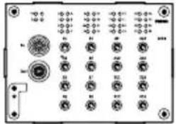 | CP-E32-M8-ELProvides32PNPinputs(IP65).ItcanonlybeconnectedtotheCPIsystemwith extendedfunctions(CPImaster).TheCPmodule CP-E32-M8-ELenablesmodulediagnosisand modulemonitoringofthesensorvoltage. | |
| Sensorconnectionsvia16M8sockets,3-pin | ||
 | CP-E16-M8-ELProvides16PNPinputs(IP65).CPmodule CP-E16-M8-ELenablesgroupdiagnosisandgroup monitoringofthesensorvoltage.Agroupconsists of4inputs. | |
| Sensorconnectionsvia8M12sockets,5-pin | ||
 | CP-E16-M12-ELProvides16PNPinputs(IP65).CPmoduleCP-E16-M8-ELenablesgroupdiagnosis andgroup monitoringofthesensorvoltage.Agroupconsistsof4inputs. | |
Tab. 4/1:Overviewofinputmodules
4.1.1 Displayandconnectingelements
The following diagram show the display and connecting elementsofinputmodule CP-E32-M8-EL.

1 CPI connection incoming
2 CPI connectioncontinuing
3 Fasteningholewithearthconnection
4 Fasteningholes
5 StatusLEDCPcommunication (PS, green)
6 StatusLEDshortcircuit/overloadin sensorsupply(red)
7 StatusLEDsforinputs (statusdisplay, green)
8 Mountingforinscriptionlabelholder (type:ASCF-H-E2)
9 Module designation
1032sensorconnections(twoinputsper socket)
Fig. 4/1: DisplaycomponentsandconnectingelementstypeCP-E32-M8-EL
The following diagram show the display and connecting elementsofinputmodule CP-E16-M8-EL.

1 CPI connection incoming
2 CPI connectioncontinuing
3 Fasteningholewithearthconnection
4 Fasteningholes
5 StatusLEDCPcommunication (PS, green)
6 StatusLED(module)short circuit/overloadinsensorsupply(red)
7 StatusLEDsforinputs (statusdisplay, green)
8 StatusLED(group)
shortcircuit/overloadinsensorsupply
(red)
9 Mountingforinscriptionlabelholder (type:ASCF-H-E2)
10Moduledesignation
11 16 sensorconnections(oneinput per socket)
Fig. 4/2: DisplaycomponentsandconnectingelementstypeCP-E16-M8-EL
The following diagram show sth e display and connecting elementsofinputmoduleCP-E16-M12-EL.

1 CPI connection incoming
2 CPI connectioncontinuing
3 Fasteningholewithearthconnection
4 Fasteningholes
5 StatusLEDCPcommunication (PS, green)
6 StatusLED(module)short circuit/overloadinsensorsupply(red)
7 StatusLEDsforinputs (statusdisplay, green)
8 StatusLED(group)short circuit/overloadinsensorsupply(red)
9 Mountingforinscriptionlabelholder (type: ASCF-H-E2)
10 Module designation
1116sensorconnections(twoinputs per socket)
Fig. 4/3: DisplaycomponentsandconnectingelementstypeCP-E16-M12-EL
4.2Mounting
The input modules are intended for fitting onto a wall or onto H-rails. Take into account the following dimensions and weights:
| Type | DimensionsWeight | |
| CP-E32-M8-ELapprox. | 143x104x30mmapprox.260g | |
| CP-E16-M8-ELapprox. | 143x104x30mmapprox.260g | |
| CP-E16-M12-ELapprox. | 143x104x30mmapprox.260g |
Tab. 4/2:Dimensionsoftheinputmodule
FittingontoawallThefollowingdiagramshowsthedimensionsfortheholes. Alwaysfasteneachmodulewith4screwsandalockingdisc. Tighteningtorqueofthefasteningscrews:1.2±0.2Nm.

Fig. 4/4: FittingdimensionsinputmoduleCP-E...-EL
4.InputmodulestypeCP-E16-M...-ELandCP-E32-M8-EL
H-railmountingThemoduleissuspendedfromaboveintheH-rail(seearrow
AinFig. 4/5).
Themoduleisearthedviatheclampingcomponent(see arrowBinFig. 4/5).Theclampingcomponentandthemountingscrewareincludedwiththemodule.

Fig. 4/5:H-railmountinginputmoduleCP-E...-EL
4.InputmodulestypeCP-E16-M...-ELandCP-E32-M8-EL
4.3Labellingofinscriptionlabelholder
Inscriptionlabelholderswithpartnumber547473(type ASCF-H-E2)areprovidedforlabellingtheELmodules.You canfindthedimensionsoftheinscriptionfieldinFig.4/6.

Fig. 4/6: InscriptionlabelholdersforELmodules, typeASCF-H-E2(dimensionsinmm)
4.4 Installation

Warning
Suddenunexpectedmovementsoftheconnectedactuatorsandundefinedswitchingstatesoftheelectroniscan causeinjurytohumanbeingsanddamagetoproperty.
Beforecarryingoutinstallationandmaintenancework, switchoffthefollowing:
–The operating and load voltages supply on the CP master (e.g. CPI/CP field bus node)
-Separatepowersupplies

Warning
Incorrectormissingearthingmeasurescancauseinterferenceduetoelectromagneticinfluences.
Connecttheearthconnectiononthehousingwithlow impedance(shortcablewithlargecross-sectionalarea) totheearthpotential.
Asuitablecablelugissuppliedwiththemodule.

Note
-Withwallmounting,earthingisdoneviaaearthing cable.
-With H-railmounting, earthing is done via a clamping component.
4.4.1 Connecting sensors

Caution
Longsignalcablesreducetheimmunitytointerference. Donotexceedthemaximumpermittedsignalcablelength of30m.

UseplugsandcablesfromtheFestorange(seeAppendix A.6)forconnecting sensors.
ForCPlinputmodules:
- Tightentheplugswiththeaidoftheunionnutinorderto preventunintentionalloosening, e.g. duetoshock.
- Seal unused connections with protective caps. Only in this way can you comply with protection class IP65. Use protective caps from the Festo range (see Appendix A.6).

Furtherinformationonconnectorsetsaswellasinstructions onhandlingthemcanbefoundinAppendixA.6.4.
Pinallocation(PNPinputs)
The following diagramsshowasanexamplethepinallocation of the sensor connections of the different CP...EL input modules.
Pinallocation
1 1:24 V
2: |x+1
3:0 V
4:1x
Ix=Inputx

Fig. 4/7: PinallocationtypeCP-E32-M8-EL
Pinallocation
1 1:24 V
3:0 V
4:1x
Ix=Inputx

Fig. 4/8: PinallocationtypeCP-E16-M8-EL
Pinallocation
1 1:24 V
2:1x+1
3:0 V
4:1x
5:FE
Ix=Inputx

Fig. 4/9: PinallocationtypeCP-E16-M12-EL
UsescrewconnectorplugsfromtheFestorange (seeAppendixA.6.4)forconnecting sensors.
4.4.2 ConnecttheinputmoduletotheCPstring

Caution
FaultindatatransferontheCPstring.
Notethemaximumpermittedstringlengthsinthemanual fortheCPI/CPmasterused.
Youwillthenavoidfaultsindatatransferbetween the inputmoduleandtheCPI/CPmaster.

Caution
Functionaldamage
Notethemaximumpermittedstringlengthsinthemanual fortheCPmasterused.
UseonlytheintendedoriginalcabletypeKVI-CP-3-...from FestoforconnectingtheCPmodules,seemanualforthe CPmasterused.

Note
Specificationsonthecurrentconsumptionofthedifferent CPmodulescanbefoundintherelevantmanuals.
The following functions are provided for the module via the CPcable:
-Operatingvoltageforinternalelectronics
-Connectionfordataexchange
-Operatingvoltagefortheconnectedsensors
TheCPImodulesareconnectedsequentially.TheM9plugistheincominginterface;theM9socketisthecontinuedinterface(see Fig. 4/1 to Fig. 4/3).
If the continuing CP connection is not used:
- SealtheCPconnectionwithaprotectivecaptype FLANSCHDOSESER.712, partno.356684 (accessories). Onlyinthiswaycanyoucomplywithprotectionclass IP65.

Note
The continuing CP connection can only be used in conjunction with a CPI master (with extended functions).
4.5 Diagnostics
4.5.1 DiagnosticsviaLEDs
StatusLED
CPcommunication(PS)
Theoperatingstatusoftheinputmoduleisshownbymeans ofthestatusLEDCPcommunication(seeTab. 4/3).
| LEDPS(green) | OperatingstatusErrorhandling | |
| LEDlightsup | Operatingvoltageapplied,CP communicationOK | None |
 LEDisout LEDisout | -Operatingvoltagenotap- pliedornoconnectionto CPI/CPmaster-CPIinputmodulenotcon- tainedinstringassignment oftheCPI/CPmaster | •ChecktheCPI/CPcableandtheoperating voltageconnectionontheCPI/CPmaster•SavetheCPstringassignmentontheCPI/CP master(seemanualfortheCPI/CPmaster) |
 LEDflashes LEDflashes | -Undervoltageinsensorsup- ply(<17V) | •Eliminateundervoltage |
Tab. 4/3: StatusLEDCPcommunication(PS)
StatusLED
Shortcircuit/overload
Shortcircuitoroverloadofthesensorsupplyisshownby meansofthestatusLEDshortcircuit/overload(seeTab. 4/4 and Tab. 4/5).
| LED(hed) module | OperatingstatusErrorhandling | |
 LEDisout LEDisout | - N o shortcircuit/overloadin sensorsupply | •None |
 LEDlightsup LEDlightsup | OnlyforCP-E16-M8-ELand CP-E16-M12-EL:-Shortcircuit/overloadin sensorsupply (displaymodule) 1permodule,lightsupwhen agroupLED ↓ lightsup | •Removeshortcircuitand,ifapplicable, deleteerror |
 LEDlightsup LEDlightsup | OnlyforCP-E32-M8-EL:-Shortcircuit/overloadin sensorsupply (displaymodule) 1permodule,lightsupwhen aninputisfaulty. | •Removeshortcircuitand,ifapplicable, deleteerror |
| LED(ied) group | OperatingstatusErrorhandling | |
| [XYZW] LEDisout | - N o shortcircuit/overloadin sensorsupply | •None |
 LEDlightsup LEDlightsup | OnlyforCP-E16-M8-ELand CP-E16-M12-EL:-Shortcircuit/overloadin sensorsupply(Displaygroup,seeFig. 4/2 andFig. 4/3)1perfourinputs,lightsup whenoneinputpergroupis faulty. | •Removeshortcircuitand,ifapplicable,deleteerror |
Tab. 4/4:StatusLED(displaymodule)shortcircuit/overload
Tab. 4/5: StatusLED(displaygroup)shortcircuit/overload
Reactiontoshortcircuitinthesensorsupply
If thereisashortcircuit, theinputmodulewillswitchoffthe powersupplytothesensorsandcommunicatethefaultto theCPI/CPmaster. ThestatusLEDswillbeswitchedoff and theinputsofthemodulesupplya0-signal. Aftertheshort circuitoroverloadhasbeeneliminated, themodulemustbe separatedfromthesupplyvoltageinordertoresettheshort circuit/overload.
StatusLEDs
Statusdisplayforinput
AbovethesensorconnectionsthereisagreenLEDforevery input. Thisshowsthesignalstatusattherelevantinput.
| LEDstatusof input | Signalstatus |
 | Logical1(signalpresent) |
| LEDlightsup | |
| [kCXO] | Logical0(nosignal) |
| LEDisout |
Tab. 4/6: StatusLEDsforstatusdisplayofinput
4.5.2 Diagnostics using fieldbus
Depending on the CPI/CP master used, the CP module type CP-...-EL provided different diagnostic information on fault searching.
| Master | Diagnosticsof shortcircuit/over-loadinsensor supply | Diagnostics, undervoltage, sensorsupply |
| CPmaster (withoutextended functions) | YesNo | |
| CPImaster (withextended functions) | YesYes |
Tab. 4/7: Diagnostic information

Note
Instructionsonevaluatingthediagnosticmessagecanbe foundinthemanualfortherelevantCPI/CPmaster.
OutputmoduletypeCP-A08-M12-EL-Z
Chapter5
Contents
5. Output module type CP-A08-M12-EL-Z 5-1
5.1FunctionoftheoutputmoduletypeCP-A08-M12-EL-Z5-3......
5.1.1 Display and connecting elements 5-4
5.2Mounting5-5
5.3Labellingofinscriptionlabelholder .... 5-7
5.4 Installation 5-8
5.4.1 Connect external load supply 5-9
5.4.2 Connecting the actuators 5-10
5.4.3 Connect the output module to the CP string 5-11
5.5 Diagnostics 5-13
5.5.1 Diagnostics via LEDs 5-13
5.5.2 Diagnostics using fieldbus 5-16
5.1 FunctionoftheoutputmoduletypeCP-A08-M12-EL-Z
OutputmoduletypeCP-A08...-M12-EL-Zprovideseightuni-versallyusabledigitaloutputsforcontrollinglow-currentconsumingdevices(bulbs,furthervalvesetc.).
| Productillustration | TypeExplanation | |
| Actuatorconnectionsvia8socketswithM12thread | ||
 | CP-A08-M12-EL-ZProvides8PNPoutputs(IP65).CPmoduleCP-A08-M12-EL-Zhaschannel-by-channelmonitoringofshortcircuit/overloadoftheoutputs. | |
Tab. 5/1:Overviewofoutputmodules
5.1.1 Display and connecting elements
The following diagram show sthedisplay and connecting element sofoutput module CP-A08-M12-EL-Z.
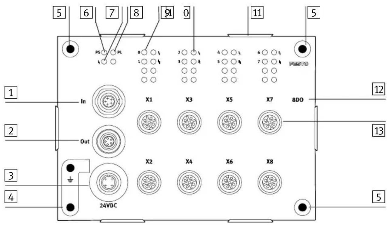
1 CPI connection incoming
2 CPI connectioncontinuing
3 Loadsupplyforoutputs
4 Fasteningholewithearthconnection
5 Fasteningholes
6 StatusLEDCPcommunication (PS, green)
7 StatusLEDoutput(module)short circuit/overload(red)
8 StatusLED
Loadsupply(PL, green)
9 StatusLEDsforoutputs (statusdisplay, yellow)
10 StatusLEDoutput(channel)short circuit/overload(red)
11 Mountingforinscriptionlabelholder (type:ASCF-H-E2)
12 Module designation
138outputs(1outputpersocket)
Fig. 5/1: DisplaycomponentsandconnectingelementstypeCP-A08-M12-EL-Z
5.2Mounting
Theoutputmoduleisintendedforfittingontoawalloronto profiles.Takeintoaccountthefollowingdimensionsand weights:
| Type | DimensionsWeight | |
| CP-A08-M12-EL-Zapprox.143x104x30mmapprox.260g | ||
Tab. 5/2:Dimensionsofoutputmodule
FittingontoawallThefollowingdiagramshowsthedimensionsfortheholes. Alwaysfasteneachmodulewith4screwsandalockingdisc. Tighteningtorqueofthefasteningscrews:1.2±0.2Nm.
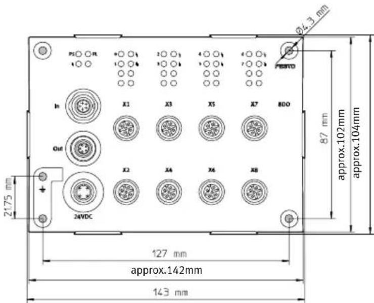
Fig. 5/2: Installation dimensionsofoutputmodule CP-A08-M12-EL-Z
H-railmountingThemoduleissuspendedfromaboveintheH-rail(seearrow
AinFig. 5/3).
Themoduleisearthedviatheclampingcomponent(see arrowBinFig. 5/3).Theclampingcomponentandthemountingscrewareincludedwiththemodule.

Fig. 5/3:H-railmountingofoutputmodules CP-A08-M12-EL-Z
- OutputmoduletypeCP-A08-M12-EL-Z
5.3 Labellingofinscriptionlabelholder
Inscriptionlabelholderswithpartnumber547473(type ASCF-H-E2)areprovidedforlabellingtheELmodules.You canfindthedimensionsoftheinscriptionfieldinFig. 5/4.

Fig. 5/4: InscriptionlabelholdersforELmodules, typeASCF-H-E2(dimensionsinmm)
5.4 Installation

Warning
Suddenunexpectedmovementsoftheconnectedactuatorsandundefinedswitchingstatesoftheelectroniscan causeinjurytohumanbeingsanddamagetoproperty.
Beforecarryingoutinstallationandmaintenancework, switchoffthefollowing:
-OperatingandloadvoltagesupplyfortheCPmaster (e. g.CPfieldbusnode)
-Separatepowersupplies

Warning
Incorrectormissingearthingmeasurescancauseinterferenceduetoelectromagneticinfluences.
Connecttheearthconnectiononthehousingwithlow impedance(shortcablewithlargecross-sectionalarea)to theearthpotential.
Asuitablecablelugissuppliedwiththemodule.

Note
-Withwallmounting,earthingisdoneviaaearthing cable.
-With H-railmounting, earthing is done via a clamping component.
- OutputmoduletypeCP-A08-M12-EL-Z
5.4.1 Connectexternalloadsupply
The output module CP-A08-M12-EL-Zissupplied via an external load supply 24 V to supply the actuators.
-Powermustbesuppliedviaapowersupplyunitthat meetsEN60204-1/IEC204(PELVpowersupplyunit).
-Max.0.5Aisavailableperchannel.
-The outputs are designed to be short-circuitproof and overloadproof channel-by-channel.
5.4.2 Connectingtheactuators

Forconnectingtheactuators,useplugsandcableswithM12 unionnutfromtheFestorange(seeAppendixA.6).
- Tightentheplugswiththeaidoftheunionnutinorderto preventunintentionalloosening,e.g.duetoshock.
- Sealunusedconnectionswiththeprotectivecapssupplied.Onlyinthiswaycanyoucomplywithprotection classIP65.
Pinallocation
The following diagram shows as an example the pin allocation of the actuator connections on the CPl output module.

Whenswitchinginductiveloads, besuretouseasuitable safetycircuit(e.g.free-whilingdiode).
5.4.3ConnecttheoutputmoduletotheCPstring

Caution
FaultindatatransferontheCPstring.
Notethemaximumpermittedstringlengthsinthemanual fortheCPmasterused.
Youwillthenavoidfaultsindatatransferbetweenthe inputmoduleandtheCPmaster(e. g.CPfieldbusnode).

Caution
Functionaldamage
Notethemaximumpermittedstringlengthsinthemanual fortheCPmasterused.

UseonlytheintendedoriginalcabletypeKVI-CP-3-...from FestoforconnectingtheCPmodules,seemanualfortheCP masterused.
Note
Specificationsonthecurrentconsumptionofthedifferent CPmodulescanbefoundintherelevantmanuals.
The following functions are provided for the module via the CPIcable:
-Operatingvoltageforinternalelectronics
-Connectionfordataexchange
TheCPImodulesareconnectedsequentially.TheM9plugis theincominginterface;theM9socketisthecontinuedinterface(see Fig. 5/1).
If the continuing CP connection is not used:
- SealtheCPconnectionwithaprotectivecaptype FLANSCHDOSESER.712, partno.356684(accessories). Onlyinthiswaycanyoucomplywithprotectionclass IP65.

Note
CheckwithintheframeworkofyourEMERGENCYSTOP circuit,toascertainthemeasuresnecessaryforputting yourmachine/systemintoasafestateintheeventofan EMERGENCYSTOP(e.g.switchingofftheoperatingvoltage forthevalvesandoutputmodules,switchingoffthecompressedair).
5.5 Diagnostics
5.5.1 DiagnosticsviaLEDs
StatusLED
CPcommunication(PS)
Theoperatingstatusoftheoutputmoduleisshownby
meansofthestatusLEDCPcommunication(seeTab.5/3).
| LEDPS(green) | OperatingstatusErrorhandling | |
 LEDlightsup LEDlightsup | Operatingvoltageapplied,CP communicationOK | None |
 LEDisout LEDisout | -Operatingvoltagenotap- pliedornoconnectionto CPI/CPmaster-CPIoutputmodulenotcon- tainedinstringallocationof theCPI/CPmaster | •ChecktheCPI/CPcableandtheoperating voltageconnectionontheCPI/CPmaster•SavetheCPstringallocationontheCPI/CP master(seemanualfortheCPI/CPmaster) |
Tab. 5/3: StatusLEDCPcommunication(PS)
StatusLED
Loadsupply(PL)
Short circuit or overload of the actuator supply is shown by means of the status LED short circuit/overload (see Tab. 5/4).
| LEDPL(green) | OperatingstatusErrorhandling | |
 LEDlightsup LEDlightsup | LoadsupplyOKNone | |
 LEDflashes LEDflashes | -Undervoltageinactuator supply(<17.5V) | •ChecktheCPcableandtheoperatingvoltage connectionontheCPI/CPmaster |
 LEDisout LEDisout | -Loadsupplymissing(<11V)•Check theCPcableandtheoperatingvoltage connectionontheCPI/CPmaster |
Tab. 5/4: StatusLEDloadsupply(PL)
StatusLEDs Statusdisplayofoutput
NexttotheactuatorconnectionsthereisayellowLEDfor everyoutput. Thisshowsthestatusofthesignalatthe relevantoutput.
| LEDstatusof output | Status |
| LEDlightsup | Outputsupplies1-signal |
| ○ LEDisout | Outputsupplies0-signal |
Tab. 5/5:StatusLEDsforstatusdisplayofoutput
StatusLEDs Shortcircuit/overload output
NexttotheactuatorconnectionsthereisaredLEDforeach output. This shows a short circuit or overload at the output.
| LED(led) module | OperatingstatusErrorhandling | |
 LEDisout LEDisout | - N o shortcircuit/overload•None | |
 LEDlightsup LEDlightsup | Displaymodule:(1permodule, lightsupwhen anoutputLEDlightsup)-Shortcircuit/overloadout-put(displaymodule) | •Eliminateshortcircuitanddeletethefault 1) |
| 1) Faultwillnotbedeletedautomatically. | ||
| LED(led) channel | OperatingstatusErrorhandling | |
 LEDisout LEDisout | - N o shortcircuit/overload•None | |
 LEDlightsup LEDlightsup | Displaychannel: (1peroutput)-Shortcircuit/overloadout-put(displayoutput) | •Eliminateshortcircuitanddeletethefault 1) |
| 1) Faultwillnotbedeletedautomatically. | ||
Tab. 5/6: StatusLEDshortcircuit/overloadoutput(displaymodule)
Tab. 5/7:StatusLEDshortcircuit/overloadoutput(displaychannel)
Reactiontoshortcircuitintheloadsupply
Shortcircuit/overloadIfthereisashortcircuit/overload,theoutputmodule will switchofftheoutputself-holdingandcommunicatethefault totheCPmaster.Incaseofshortcircuit,theoutputremains switchedoff.Whentheshortcircuithasbeeneliminated, deletethisfaultasfollows:
- To reactive the output, the power supply or the complete module must be separated from the powersupply. Only resetting the output does not triggere either the error message or the blocking off functions.
5.5.2 Diagnostics using fieldbus
Irrespective of the CPI/CP master used, the CP output module type CP-...-EL provides diagnostic information on fault searching.
| Master | Diagnosticsof shortcircuit/over-loadinactuator supply | Diagnostics, undervoltage, actuatorsupply |
| CPmaster (withoutextended functions) | Commonfaultmessage | |
| CPImaster (withextended functions) | YesYes | |
Tab. 5/8: Diagnostic information

Note Instructionsonevaluatingthediagnosticmessagecanbe foundinthemanualfortherelevantCPI/CPmaster.
Technicalappendix
AppendixA
Contents
A. Technical appendix ...... A-1
A.1TechnicalspecificationsA-3..
A.1.1 General technical data A-3.....
A.1.2 Technical specifications of the CLinputmodules A-4.....
A.1.3 Technical specifications of the CL output modules ..... A-6
A.1.4 Technical specifications of the EL input modules ..... A-7
A.1.5 Technical specifications of the EL output modules ..... A-9
A.2 Internal structure of the inputs A-10
A.2.1Internal structure type CP-E32-M8-EL A-10
A.2.2 Internal structure type CP-E08-M12-CL and CP-E16-M12-EL ..... A-11
A.2.3 Internal structure type CP-E08-M8-CL and CP-E16-M8-EL ..... A-12
A.2.4 Internal structure type CP-E16-KL-CL A-13
A.3 Internal structure of the outputs ..... A-14
A.3.1 Internal structure type CP-A04-M12-CL and CP-A08-M12-EL-Z ... A-14
A.4 Examples of circuitry A-15
A.4.1 Circuitry examples for inputs A-15
A.4.2 Circuitry examples for outputs A-20
A.5 General information on parameterisation ..... A-22
A.5.1 Input debounce time (only with CP-EL modules) ..... A-22
A.5.2Signalextension(onlywithCP-ELmodules) . ...... A-24
A.6 Accessories.... A-27
A.6.1 General accessories A-27
A.6.2 Accessories for modules with M12 connection ..... A-27
A.6.3 Accessories for modules with M8 connection A-28
A.6.4 Connector sets for input module type CP-E16-KL-CL.... A-29
A.1 Technical specifications
A.1.1 Generaltechnicaldata
GeneraltechnicalspecificationsoftheCPI/CPI/Omodules
| Temperaturerange:-Operation-Storage/transport | -5 °C...+50 °C-20°C...+70 °C |
| Relativeairhumidity95 %,non-condensing | |
| ProtectionagainstelectricshockasperEN60204-1/IEC204(protection againstdirectandindirectcontact) | ViaconnectiontoaPELV(ProtectedExtra-LowVoltage)powersupplyunit |
| Electromagneticcompatibility-Interferenceemission-Interferenceimmunity | Seedeclarationofconformity→www.festo.com |
| Vibrationandshock-Vibration-Shock | TestedasperDIN/IEC68/EN 60068part2-6;0.35 mmpathat10 ... 60Hz;5 gaccelerationat60 ... 150 HzTestedasperDIN/IEC68/EN60068part2-27;±30gat11 msduration;5shocksineachdirection |
Tab. A/1: Technical specification of CPI/O modules (general)
A.1.2 Technical specifications of the CLinput modules
| TechnicalspecificationsType CP-E08-M12-CL,typeCP-E08-M8-CL | |
| GeneraltechnicaldataSeesectionA.1.1 | |
| ProtectionclassasperEN60529;plugcon- nectorinsertedorfittedwithprotectivecap | IP65/IP67 |
| Digitalinputs-Configuration8inputsperIEC1131-2type2, -Logiclevel: 1-signal 0-signal | 24VDC,positive-switching(PNP) |
| >11V<5V | |
| -Currentconsumption(at24 V)(inputcurrentfromsensortoinput) | At“logical1”Typ.8mA |
| -Responsedelay(at24V)Typical3ms | |
| Sensorvoltagesupply-Nominalvalue-Tolerance | ViatheCPconnection24VDCSeemanualforCPmaster |
| -Internalcurrentconsumptionoftheelec-tronicsviatheCPconnection(allinputsin 0-status) | <35mA |
| LoadcapacitySum>0.8A(electronicshort-circuit protection) | |
| Electricalisolation | None |
| TechnicalspecificationsTypeCP-E16-KL-CL | |
| GeneraltechnicaldataSeesectionA.1.1 | |
| ProtectionclassasperEN60529IP20 | |
| Digitalinputs-Configuration | 16 inputs as per IEC 1131-2 type 2 inputs 24 V DC, positiveornegativeswitching |
| -Logiclevel1-signal0-signal | ≥8.6V≤6V |
| -Currentconsumption(at24 V)(inputcurrentfromsensortoinput) | At“logical1”Typ.8mA |
| -Responsedelay(at24V)Typical3ms | |
| Sensorvoltagesupply-Ratedvalue(protectedagainstincorrect polarity)-Tolerance | ViatheCPconnection24VDCSeemanualforCPmaster |
| -Internalcurrentconsumptionoftheelec-tronicsviatheCPconnection(allinputsin 0-status) | <35mA |
| LoadcapacityTotal>0.8A(electronicshort-circuitprotection) | |
| ElectricalisolationNone | |
Tab. A/2: TechnicalspecificationstypeCP-E08-M12-CLandtypeCP-E08-M8-CL
Tab. A/3: TechnicalspecificationstypeCP-E16-KL-CL
A.1.3 Technical specifications of the CL output modules
| TechnicalspecificationsTypeCP-A04-M12-CL | |
| GeneraltechnicaldataSeesectionA.1.1 | |
| ProtectionclassasperEN60529;plugconnectorinsertedorfittedwithprotectivecap | IP65/IP67 |
| ElectricalisolationNone | |
| Digitaloutputs-Configuration-Loadcapacityyperdigitaloutput | 4outputsasperIEC1131-2;24VDCpositive-switching0.5A |
| -Electronicfuse(shortcircuit,overload)TriggercurrentResponsetime | Min.750mAMax.1.5ms |
| InternalcurrentconsumptionoftheelectronicsviatheCPconnection | < 35mA |
Tab. A/4: Technical specificationstype CP-A04-M12-CL
A.1.4 Technical specifications of the EL input modules
| TechnicalspecificationsType CP-E32-M8-EL | |
| GeneraltechnicaldataSeesectionA.1.1 | |
| ProtectionclassasperEN60529;plugcon- nectorinsertedorfittedwithprotectivecap | IP65 |
| Digitalinputs-Configuration32inputsperIEC1131-2type2, -Logiclevel: 1-signal 0-signal-Currentconsumption(at24 V)(inputcur- rentfromsensortoinput)-Responsedelay(at24V)Typ.3ms,canbeparamet | 24VDC,positive-switching(PNP)>11V<5V |
| At“logical1” Typ.8mAtrised:0.5ms,3ms,10ms, 20ms | |
| Sensorvoltagesupply-Nominalvalue-Tolerance-Internalcurrentconsumptionoftheelec-tronicsviatheCPconnection(allinputsin 0-status) | ViatheCPconnection 24VDC SeemanualforCPmaster(20.4V...26.4V) |
| Max.75mAat24V | |
| Load capacity | Total max.1.35 A/500 μF (electronic short-circuit protection) |
| Electricalisolation | None |
| TechnicaldataType CP-E16-M8-EL,CP-E16-M12-EL | |
| GeneraltechnicaldataSeesectionA.1.1 | |
| ProtectionclassasperEN60529;plugconnectorinsertedorfittedwithprotectivecap | IP65 |
| Digitalinputs-Configuration16inputsperIEC1131-2type2,-Logiclevel:1-signal0-signal-Currentconsumption(at24 V)(inputcurrentfromsensortoinput)-Responsedelay(at24V)Typ.3ms,canbeparametrised:0.5ms,3ms,10ms,20ms | 24VDC,positive-switching(PNP)> 11V< 5V |
| > 11V< 5V | |
| At“logical1”Typ.8mA | |
| trised:0.5ms,3ms,10ms,20ms | |
| Sensorvoltagesupply-Nominalvalue-Tolerance-InternalcurrentconsumptionoftheelectronicsviatheCPconnection(allinputsin0-status) | ViatheCPconnection24VDCSeemanualforCPmaster(20.4V...26.4V) |
| Max. 75mAat24V | |
| LoadcapacityMax.130mA/100μFpergroup(electronicshort-circuitprotection) | |
| ElectricalisolationNone | |
Tab. A/5: TechnicaldatatypeCP-E32-M8-EL
Tab. A/6: TechnicaldatatypeCP-E16-M8-ELandCP-E16-M12-EL
A.1.5 Technical specifications of the EL output modules
| TechnicaldataTypeCP-A08-M12-EL-Z | |
| GeneraltechnicaldataSeesectionA.1.1 | |
| ProtectionclassasperEN60529;plugconnectorinsertedorfittedwithprotectivecap | IP65 |
| Digitaloutputs-Configuration-Loadcapacityperdigitaloutput | 8outputsasperIEC1131-2;24VDCpositive-switchingMax.0.5A |
| -Electronicfuseperchannel(shortcircuit/overload)TriggercurrentResponsecharacteristics | Min.1.0ASlow-blowing |
| Actuatorsupply-Nominalvalue-Tolerance | 24VDC24VDC±25%(18V...30V) |
| InternalcurrentconsumptionoftheelectronicsviatheCPconnection(alloutputs in0-status) | Max. 35mAat24V |
| ElectricalisolationNone |
Tab. A/7: Technicaldatatype CP-A08-M12-EL-Z
A.2Internalstructureoftheinputs
A.2.1 Internal structure type CP-E32-M8-EL

flowchart
graph TD
    Pin1["Pin1"] -->|24 V| Pin2["Pin2"]
    Pin2 -->|0 V| Pin3["Pin3"]
    Pin3 -->|2 V| Pinassignment["Pinassignment\n1: + 24 V\n2: lx+1\n3: 0V\n4: lx"]
    Pin3 -->|6 V| GreenLEDIx["GreenLEDIx+1\n5: PLC/I-PCIx(viafieldbus)\n6: Logicidentifierlx\n7: GreenLEDIx\nlx=Inputx"]
    Pin3 -->|4 V| GreenLEDIx
    Pin3 -->|5 V| GreenLEDIx
    Pin3 -->|6 V| GreenLEDIx
    Pin3 -->|7 V| GreenLEDIx
    Pin3 -->|4 V| Pinassignment
    Pin3 -->|7 V| Pinassignment
    Pin3 -->|6 V| Pin3
    Pin3 -->|7 V| Pin3
Fig. A/1: Internal structure type CP-E32-M8-EL
A.2.2InternalstructuretypeCP-E08-M12-CLandCP-E16-M12-EL

1 Pinassignment
1:+ 24 V
2: | x + 1|
3:0V
4:1x
5:FE
4 GreenLEDIx+1
5 PLC/I-PCIx(viafieldbus)
6Logicidentifierlx
7 GreenLEDlx
2PLC/I-PCIx+1(viafieldbus)
Ix=Inputx
3 Logicrecognitionix+1
Fig. A/1:InternalstructuretypeCP-E08-M12-CLandCP-E16-M12-EL
A.Technicalappendix
A.2.3 Internal structure type CP-E08-M8-CL and CP-E16-M8-EL

Fig. A/2: Internal structure type CP-E08-M8-CL and CP-E16-M8-EL
A. Technical appendix
A.2.4InternalstructuretypeCP-E16-KL-CL

flowchart
graph TD
    A["Pin+"] --> B["24 V"]
    B --> C["Pin0...15"]
    C --> D["3"]
    D --> E["0 V"]
    E --> F["Pin-"]
    style D fill:#f9f,stroke:#333
    note1["1 Pinassignment +:24 V\n0...15:lx+n -:0 V"] --> D
    note2["2 PLC/IPC1x(e.g.viafieldbus)\n3 Logicidentifier1x\nlx=Inputx"] --> D
Fig. A/3: Internal structure type CP-E16-KL-CL
A.3 Internal structure of the outputs
A.3.1 Internal structure type CP-A04-M12-CLand CP-A08-M12-EL-Z
Nameforports:E.g.:1forCLmodules,x1forELmodules

1 Actuatorconnection
1:n.c.
2:Portx1,(x3):x+1,(x+3)
Portx2,(x4):n.c.(notconnected)
3:0 V
4:Portx1:0x
Portx3:Ax+2
5:FE
2 PLC/IPCOx(e.g.viafieldbus)
3 Diagnosis
-Shortcircuit/overload
-Loadvoltagefailure.
Undervoltageinloadsupply
4 GreenLED(PL)
5 RedLED(faultsymbol)
6 YellowLED(output)
Ox=Outputx
Fig. A/4:InternalstructuretypeCP-A04-M12-CLandCP-A08-M12-EL-Z
A. Technical appendix
A.4Examplesofcircuitry
A.4.1 Circuitryexamplesforinputs
ExampleofcircuitrytypeCP-E32-M8-EL
1 Pinassignment
1:24 V
2:1x+1
3:0 V
4:1x
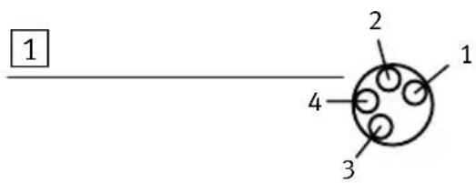
2 Dualdistributor (T-piece)
3 Sensor2(lx+1)
4 Sensor1(lx)
$$ \mathrm{lx} = \text { Inputx } $$

Fig. A/5:ExampleofcircuitrytypeCP-E32-M8-EL
ExampleofcircuitrytypeCP-E08-M12-CLand CP-E16-M12-EL
1 Pinassignment
1:24 V
2:1x+1
3:0 V
4:1x
5:Groundterminal
2 Dualdistributor (T-piece)
3 Sensor2(lx+1)
4 Sensor1(lx)
Ix=Inputx
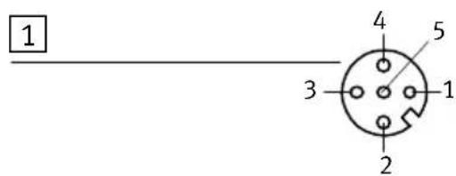

Fig. A/6:ExampleofcircuitrytypeCP-E08-M12-CLandCP-E16-M12-EL
ExamplesofcircuitrytypeCP-E08-M8-CLand CP-E16-M8-EL

Fig. A/7:ExampleofcircuitrytypeCP-E08-M8-CLandCP-E16-M8-EL
CircuitryexampletypeCP-E16-KL-CL
Tworowsofthethree-rowconnectorsocketareintendedas distributorboardsforthesensorsupply.Theserowsareeach connectedinternally.Theupperrow(bluepushbuttons)is intendedforthe0Vdistributor;thecentrerow(redpushbuttons)isintendedforthe24Vdistributor.Therelevantvoltagemustbe suppliedbymeansofanexternalbridgefrom theterminals+and—(lowerrow).
1 Externalbridgefor potential distribution (24 V)
2 Externalbridge forpotential distribution(0V)
3 Pinassignment +:24 V 0...7:1x+n -:0 V
4 Contact
5 Two-wiresensor (positive-switching)
6 Three-wiresensor (positive-switching)
Ix=Inputx

Fig. A/8:CircuitryexampletypeCP-E16-KL-CL with3-rowconnectorsettypeCP-E16-KL-CL
CircuitryexampletypeCP-E16-KL-CLwithsingle-row connectorsocket
1 Externalpotential distribution (24 V)
2 Pinassignment
+:24 V
0...7:lx+n
-:0 V
3 Externalpotential distribution(0V)
4 Contact
5 Two-wiresensor (positive-switching)
6 Three-wiresensor (positive-switching)
lx=Inputx
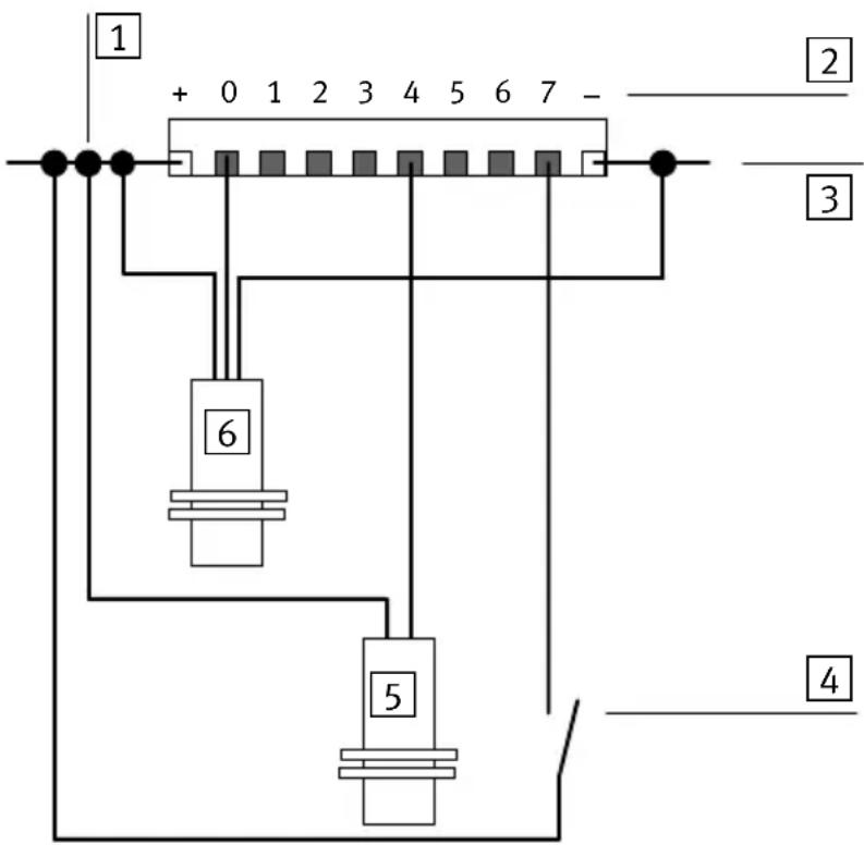
Fig. A/9:CircuitryexampletypeCP-E16-KL-CLwithsingle-rowconnectorsocket
A.4.2 Circuitryexamplesforoutputs
ExamplesofcircuitrytypeCP-A04-M12-CLand CP-A08-M12-EL-Z
Nameforports:E.g.:1forCLmodules,x1forELmodules

1 Pinassignment 1:n.c. 2:*) 3:0 V 4:0x 5:Groundterminal
2Example1
3Example2
4Notacceptable
*) - Port x0, x2, x4, x6: Ox+1, Ox+3, Ox+5, Ox+7 - Port x1, x3, x5, x7: n.c. (not connected)
Ox=Outputx n.c.=notconnected
Fig. A/10: Examples of circuitry output module type CP-A04-M12-CLand CP-A08-M12-EL-Z
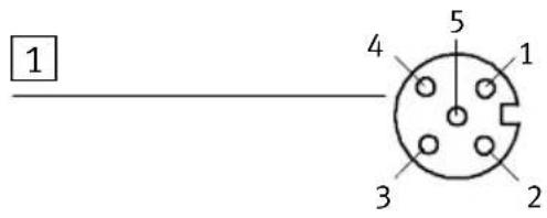
CircuitryexampletypeCP-A04-M12-CL
1 Pinassignment Port0(2):
1:n.c.
2:0x+1(0x+3)
3:0 V
4:0x+0(0x+2)
5:Groundterminal
Ports1,3:notused
2 Magnetvalve
Ox=Outputx

flowchart
graph TD
    A["1"] --> B["2"]
    B --> C["3"]
    C --> D["4"]
    D --> E["82/84"]
    E --> F["12"]
    F --> G["14"]
    G --> H["5"]
    H --> I["1"]
    I --> J["3"]
    J --> K["12/14"]
    style A fill:#f9f,stroke:#333
    style B fill:#f9f,stroke:#333
    style C fill:#f9f,stroke:#333
    style D fill:#f9f,stroke:#333
    style E fill:#ccf,stroke:#333
    style F fill:#ccf,stroke:#333
    style G fill:#ccf,stroke:#333
    style H fill:#ccf,stroke:#333
    style I fill:#ccf,stroke:#333
    style J fill:#ccf,stroke:#333
    style K fill:#ccf,stroke:#333
Fig. A/11:CircuitryexampletypeCP-A04-M12-CLwithmagnetvalve,e.g.typeJMEBH-5/2-D-...-ZSR-C
A.5 General information on parameterisation

YoucanparameterisethebehaviouroftheCPImodules(e.g. diagnosticbehaviouretc.).Accesstotheparametersdepends ontheCPImasterused:
-CPX-CPinterfaceasCPImaster:parameterisationviathe fieldbusorviathehandheld(CPX-MMI).
-CPVDirectasCPImaster:parameterisationviathefieldbus.
ThebasicsoftheparametersInputdebounce timeandSignal extensionaredescribedinwhatfollows.Furtherinformation onparameterisationcanbefoundintheCPXsystemmanual.
A.5.1 Inputdebouncetime(onlywithCP-ELmodules)
Basics
Inputdebouncingtimesarespecifiedinordertoeliminate interferingchangesofsignaledgeduringswitchingprocedures(bouncingoftheinputsignal).Forexample,mechanicalswitchesgeneratebriefundesiredsignaledgesduring switchingprocedures.Thesignalstateswhicharethereby producedcancauseinterferenceinthecontrolsequenceand shouldthereforefrequently besuppressed.
Interfering, undesiredsignaledgescanbesuppressedbya PLCprograminthehigher-ordercontroller.Interferencecan thereforebeavoided.WiththeCPIsystem, undesiredsignal edgescanbesuppressedsimplybyparameterisation.
ParameterisationintheCPIsystem
With the CPI system, the input debouncing time can be set with an appropriate module parameter. The possible input debouncing times therefore depend on the particular type of module. Typical input debouncing times are: 0.1 ms, 3ms (typical presetting), 10ms and 20ms.
Methodofoperation
Changesofedgeinthesensorsignalwillbeacceptedasalogicalinputsignal(seeFig. A/1)onlywhenthespecifieddebouncingtimehasexpired.
Dependencydiagram
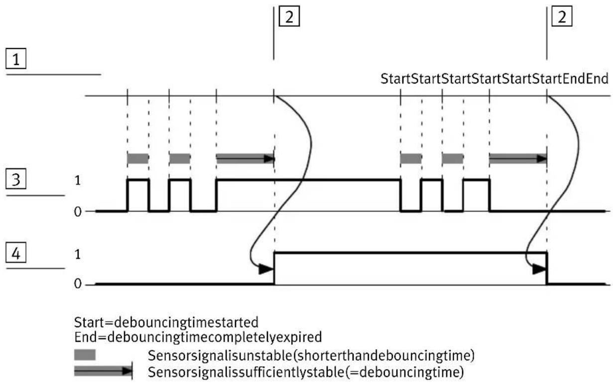
other
| State | Signal Status | Notes | |-------|---------------|-------| | 1 | Initial | SENSORSIGNALISUNSTABLE(SHORTERTHANDEBOUNCINGTIME) | | 2 | Initiated | SENSORSIGNALISSUSSURELLYSTABLE(=debouncingTIME) | | 3 | Initial | SENSORSIGNALISUNSTABLE(SHORTERTHANDEBOUNCINGTIME) | | 4 | Final | SENSORSIGNALISSUSSURELLYSTABLE(=debouncingTIME) |1 Startandend(sequence)ofthe debouncingtime
3 Sensorsignal
4 LogicalCPIsignal
2 Debouncingtimehasexpired
Fig. A/1: Inputdebouncing
A.5.2 Signaextension(onlywithCP-ELmodules)
Basics
Signalextensiontimesarespecifiedwhenveryshortsignals aretobetakenintoaccountinthecontrolprocess.Short signalscanoccur,e.g.whenanintermediatepositionisex-ceededandevaluationisnecessaryinordertoproducea time-optimisedconsequentprocessbeforeanendpositionis reached.
Dependingonthetypeof sensor,thelengthofthesignal, whichisgeneratedwhentheintermediatepositionisexceeded,canfluctuateaccordingtothepositioningspeed. Thereisadangerherethattheshortsignalsarenotalways “recognised”duetolongcycletimesofthehigher-ordercontroller.
WiththeCPIsystem, asignalextension timecanbedefined byparameterisationoftheappropriateinputsignal.Short signalswillthenalsoberecognisedreliablybythehigher-ordercontroller.
ParameterisationintheCPIsystem
With the CPI system, the signalextension time for the module is set with the appropriate module parameter. The possible signalextension times depend on the type of module. Typical signalextension times are: 0.5 ms (typical presetting), 15 ms, 50 ms and 100 ms.
Theusermustparameterisethesignalextensiontimefor activation.
Methodofoperation
Signalstatesacceptedaslogicalinputsignalsusuallyremain validatleastuntilthespecifiedminimumsignaldurationhas expired.Changeofedgewithinthemimumsignalduration areignored(see Fig. A/2).Fixeddebouncingtimesremain effective.
Case1: Changeofedgewithinthesignalextension time
TheologicalCPIsignalissuppliedwhenthesignalextension timeand,ifapplicable,thedebouncingtimehasexpired.
1 Sensorsignal
2 LogicalCPIsignal
3 Changeofedge withinthesignal extensiontime


other
| Time | Expiryofthedebouncingtime | Expiryofthesignalextensiontime | |------|---------------------------|----------------------------------| | 0 | 0 | 0 | | 1 | 1 | 0 | | 2 | 0 | 0 |Fig. A/2: Changeofedgewithinthesignalextensiontime
Case2: Changeofedgeafterexpiryofthesignal extensiontime
TheologicalCPIsignalfollowstheinputsignalandissupplied afterit. Ifadebouncingtimehasbeendefined, theologicalCPI signalissuppliedwhenthedebouncingtimehasexpired.
1 Sensorsignal
2 LogicalCPIsignal
3 Changeofedge afterexpiryofthe signalextension time


other
| Phase | Expiryofthedebouncingtime | Expiryofthesignalextensiontime | |-------|---------------------------|----------------------------------| | 1 | 1 | 0 | | 2 | 0 | 0 |Fig. A/3: Changeofedgeafterexpiryofthesignalextensiontime
A.6Accessories
A.6.1 General accessories
| Accessories | TypeDescription | |
 | ISB-8x2064identificationsigns8x20 | |
 | ASCF-H-E210inscriptionlabelsforCP-ELmodulesapprox.24x60mm | |
 | FLANSCHDOSESER.712 | -ProtectivecapsforsealingunusedCPconnectorsockets |
A.6.2AccessoriesformoduleswithM12connection
| Accessories | TypeDescription | |
 | SEA-G-S-7SEA-4GS-7-2,5SEA-GS-9SEA-GS-11-DUO | M12plugforconnectingsensorsandactuators,straight,4-pin-PG7screwconnector,forcablediameter4...6mm-PG7screwconnector,forcablediameter2.5...2.9mm-PG9screwconnector-PG11screwconnector,2cableexits(DUO) |
| SEA-M12-5GS-PG7SEA-5GS-11-DUO | M12plugforconnectingsensorsandactuators,straight,5-pin-PG7screwconnector-PG11screwconnector | |
 | KM12-DUO-M8-GDGDKM12-DUO-M8-GDWDKM12-DUO-M8-WDWD | DUOcablewith2M8plugsformoduleswithM12connection:-straight/straight-straight/angled-angled/angled |
| Accessories | DescriptionType | |
 | KM12-M12-GSGD-... KM12-M12-GSWD-... | ExtensioncableforDUOcableindifferentlengths-Straight/straight-Straight/angled |
 | ISK-M12- 1 0 protectivecapsforsealingunusedM12connector sockets | |
A.6.3 AccessoriesformoduleswithM8connection
| Accessories | TypeDescription | |
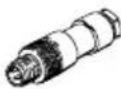 | SEA-GS-M8SEA-3GS-M8-S | M8plugforconnecting sensors, straight, 3-pin, PG7screw connector–Solderable–Screw-in |
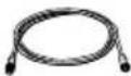 | KM8-M8-GSGD-... | Connecting cable with plug and socket, M8, 3-pin, straight/ straight indifferent lengths |
 | ISK-M8-10 protective caps for sealing unused M8 connector sockets | |
A.6.4 ConnectorsetsforinputmoduletypeCP-E16-KL-CL

Recommendation: Usetheconnectorsocketstype PS1-SAC31-30POL+LEDfortheinputmoduletypeCP-E16-KL-CL.
| SocketstypePS1-SAC31-30POL+LED | NumberConnectioncrosssection | Recommendedforconnection | |
| Tensionspringsockets,3-row+LED | 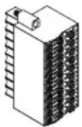 | 2seeleaflet | X1,X2 |
Tworowsofthethree-rowconnectorsocketareintendedas distributorboardsforthesensorsupply.Theserowsareeach connectedinternally(see Fig. A/8).
- Fastenthesocketswiththescrewsprovided.Themaximumtighteningtorqueis0.2Nm.
Instructionsonwiringtheconnectorsockets
Solidwiresandcableswithendsleevescanbeinsertedeasily inthedesiredtensionspringterminal.Forinsertingflexible wires,youmustuseasuitabletool(e.g.screwdriver)topress downthecolouredpushbuttonfortherelevanttensionspring terminal.
1 Tensionspring socket
2 Cable
3 Screwdriver

Fig. A/4: Wiringtheconnectorsocket
Index
AppendixB
B.Index
B. Index B-1
A
Abbreviations, product-specific ..... XIII☐
AccessoriesA-27......
C
CLinputmodules2-3......
CLoutputmodules3-3......
Connecting the actuators 3-7,5-10
Connectorsockets A-29
Diagnostics Diagnostics via LEDs .... 4-16, 5-13 Diagnostics via the fieldbus .... 4-20, 5-16
E
Earthing For wall mounting .... 4-10,5-8 ViaH-rail .... 4-10,5-8....
EL input modules 4-3
EL output modules 5-3
Exampleofcircuitryofinputs ..... A-15
Example of circuitry of outputs ..... A-20
|
Input debounce time ...... A-22
Inputmodule Connect to the node ..... 2-12, 4-14
LEDs 2-14
LEDs4-16......
InternalstructuretypeCP-E08-KL-CLA-13......
Internal structuretypeCP-E08-M12-CLA-11,A-12......
InternalstructuretypeCP-E16-M12-ELA-11
InternalstructuretypeCP-E16-M8-ELA-12......
Internalstructuretype CP-E32-M8-ELA-10......
Inscriptionlabelholder, Inscription4-9,5-7......
Intendeduse ...... VI
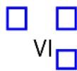
M
Mounting
Input module 2-7,4-7
Outputmodule.... 3-5,5-5
N
Notes on the use of this manual .... X
0
Outputmodule
Connect external load supply 5-9
Connect to the node 3-9,5-12
LEDs 3-10,5-13
InternalstructuretypeCP-A04-M12-CL .. ...... A-14
Internal structure type CP-A08-M12-EL-Z ..... A-14
P
Parameterisation, General information A-22
Pictograms IX
Pinallocation
Input module type CP-E32-M8-EL 4-12
Input module type CP-E16-M8-EL 4-12
Input module type CP-E16-M12-EL 4-13
OutputmoduletypeCP-A04-M12-CL 3-7...
OutputmoduletypeCP-A08-M12-EL-Z5-10......

Pinassignment
InputmoduletypeCP-E08-M12-CL2-10......
InputmoduletypeCP-E08-M8-CL2-10......
InputmoduletypeCP-E16-KL-CL2-11......


PowerunitVII
......

R
Rules for extending the CPI/CP system 1-8

S
Sensors, Connecting 2-9,4-11

Service VII

Shortcircuit/overload
Load supply 3-12,5-15
Sensor supply 2-15,4-18

Signalextensiontime...... A-24

T
Target group VII

Technicaldata
TypeCP-A08-M12-EL-Z...... A-9
Technicalspecifications
CPI/CPI/O modules (general) A-3
Type CP-A04-M12-CL A-3,A-6
Type CP-A08-M12-EL-Z A-
- FESTO
- Description Manual
- Description
- Contents
- System overview CPI/CP system ....
- Inputmodules types CP-E08-M...-CL and CP-E16-KL-CL
- Output module type CP-A04-M12-CL .....
- Intendeduse
- Selectingthepowerunit
- Warning
- Targetgroup
- Service
- Importantuserinstructions
- Dangercategories
- Caution
- Note
- Identifyingspecialinformation
- Pictograms
- Textdesignations
- Notesontheuseofthismanual
- SystemoverviewCPI/CPsystem
- System overview CPI/CP system 1-1
- 1.1SettingupCPIsystems
- Method of operation of the CPI/CP system
- SystemoverviewCPI/CPsystem
- RulesforextendingtheCPIsystem
- Rules:
- Systemoverview CPI/CP system
- Useofthel/Omodules
- Basicrulesforaddressing
- InputmoduletypesCP-E08-M...-CLand CP-E16-KL-CL
- 2.InputmoduletypesCP-E08-M...-CLandCP-E16-KL-CL2-1.....
- 2.1FunctionoftheinputmodulesCP-E08-M...-CLandCP-E16-KL-CL
- Display and connecting elements
- 2.2Mounting
- Installation
- Connecting sensors
- InthecaseofCPinputmodulestypeCP-E08-M12-CLand CP-E08-M8-CL:
- WithCPinputmoduletypeCP-E16-KL-CL:
- Pinassignment(PNInputs)
- Pinassignment
- ConnecttheinputmoduletotheCPstring
- 2.4Diagnosis
- Diagnosis via LEDs
- Reactiontoshortcircuitinthesensorsupply
- StatusLEDs
- Statusdisplayforinput
- OnlywithtypesCP-E08-M12-CLandCP-E08-M8-CL:
- Diagnosis viathefieldbus
- OutputmoduletypeCP-A04-M12-CL
- Output module type CP-A04-M12-CL 3-1
- FunctionofoutputmoduletypeCP-A04-M12-CL
- Display and connecting elements
- 3.2Mounting
- Installation
- Connectingtheactuators
- Pinallocation
- 3.3.2ConnecttheoutputmoduletotheCPstring
- Diagnostics
- DiagnosticsviaLEDs
- Reactiontoshortcircuitintheloadsupply
- Diagnostics viathefieldbus
- InputmoduletypeCP-E16-M...-ELand CP-E32-M8-EL
- 4.InputmoduletypeCP-E16-M...-ELandCP-E32-M8-EL4-1.....
- FunctionoftheinputmodulesCP-E16-M...-ELandCP-E32-M8-EL
- Displayandconnectingelements
- 4.2Mounting
- 4.3Labellingofinscriptionlabelholder
- Installation
- Connecting sensors
- ForCPlinputmodules:
- Pinallocation(PNPinputs)
- ConnecttheinputmoduletotheCPstring
- Diagnostics
- DiagnosticsviaLEDs
- Diagnostics using fieldbus
- OutputmoduletypeCP-A08-M12-EL-Z
- Output module type CP-A08-M12-EL-Z 5-1
- FunctionoftheoutputmoduletypeCP-A08-M12-EL-Z
- Display and connecting elements
- 5.2Mounting
- Labellingofinscriptionlabelholder
- Installation
- Connectexternalloadsupply
- Connectingtheactuators
- 5.4.3ConnecttheoutputmoduletotheCPstring
- Diagnostics
- DiagnosticsviaLEDs
- Diagnostics using fieldbus
- Technicalappendix
- Technical appendix ...... A-1
- A.1 Technical specifications
- A.1.1 Generaltechnicaldata
- A.1.2 Technical specifications of the CLinput modules
- A.1.3 Technical specifications of the CL output modules
- A.1.4 Technical specifications of the EL input modules
- A.1.5 Technical specifications of the EL output modules
- A.2Internalstructureoftheinputs
- A.3 Internal structure of the outputs
- A.4Examplesofcircuitry
- A.4.1 Circuitryexamplesforinputs
- ExampleofcircuitrytypeCP-E32-M8-EL
- ExampleofcircuitrytypeCP-E08-M12-CLand CP-E16-M12-EL
- CircuitryexampletypeCP-E16-KL-CL
- CircuitryexampletypeCP-E16-KL-CLwithsingle-row connectorsocket
- A.4.2 Circuitryexamplesforoutputs
- ExamplesofcircuitrytypeCP-A04-M12-CLand CP-A08-M12-EL-Z
- CircuitryexampletypeCP-A04-M12-CL
- A.5 General information on parameterisation
- A.5.1 Inputdebouncetime(onlywithCP-ELmodules)
- Basics
- ParameterisationintheCPIsystem
- Methodofoperation
- A.5.2 Signaextension(onlywithCP-ELmodules)
- Case1: Changeofedgewithinthesignalextension time
- Case2: Changeofedgeafterexpiryofthesignal extensiontime
- A.6Accessories
- A.6.3 AccessoriesformoduleswithM8connection
- A.6.4 ConnectorsetsforinputmoduletypeCP-E16-KL-CL
- Instructionsonwiringtheconnectorsockets
- Index
- AppendixB
- A
- C
- E
- |
- M
- N
- 0
- P
- R
- S
- T
Brand : Festo
Model : P.BE-CPEA-CL-IT
Category : Pneumatic module