IM01-GMDL6X - Car alarm OMEGA - Free user manual and instructions
Find the device manual for free IM01-GMDL6X OMEGA in PDF.


| Product Type | Car Alarm |
| Brand | Omega |
| Model | IM01-GMDL6X |
| Category | Vehicle Security System |
| Power Supply | 12V DC (vehicle battery) |
| Operating Frequency | 433.92 MHz |
| Remote Range | Up to 100 meters (line of sight) |
| Number of Remote Fobs Included | 2 |
| Main Functions | Remote lock/unlock, panic alarm, shock sensor, engine immobilizer |
| Additional Features | Silent arm/disarm, valet mode, auto-lock |
| Control Unit Dimensions | Approximately 100 x 70 x 25 mm |
| Control Unit Weight | Approximately 200 grams |
| Installation | Professional installation recommended |
| Warranty | 1 year limited warranty |
| Maintenance | Keep dry; clean with a soft, dry cloth |
| Safety | Overload protection, anti-theft circuitry |
| Spare Parts Available | Remote fobs, fuses, control unit |
| Repair | Contact authorized Omega service center |
Frequently Asked Questions - IM01-GMDL6X OMEGA
User questions about IM01-GMDL6X OMEGA
0 question about this device. Answer the ones you know or ask your own.
Ask a new question about this device
Download the instructions for your Car alarm in PDF format for free! Find your manual IM01-GMDL6X - OMEGA and take your electronic device back in hand. On this page are published all the documents necessary for the use of your device. IM01-GMDL6X by OMEGA.
USER MANUAL IM01-GMDL6X OMEGA
Downloadable Firmware for Platform# 01: AMDL, FODL, GMDL6, GMDL7, HODL4, HYDL, KIADL, KIADL2, TOYDL, VWDL, VWDL2
WARNING: Before beginning your install go to www.XpressDownload.com and be sure to print the LATEST corresponding installation manual for the firmware that is flashed to the platform you are using.
Section A
See Wire Connection Guide for detailed information regarding wire functionality
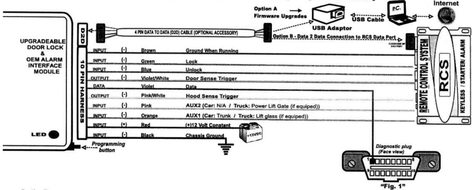
flowchart
graph LR
    A["UPGRADEABLE DOOR LOCK & OEM ALARM INTERFACE MODULE"] --> B["D2D"]
    B --> C["10 PIN HARNESS"]
    C --> D["Programming button"]
    D --> E["Programming button"]
    E --> F["4 PIN DATA TO DATA (D2D) CABLE (OPTIONAL ACCESSORY)"]
    F --> G["USB Adaptor"]
    G --> H["USB Cable"]
    H --> I["Option A Firmware Upgrades"]
    I --> J["USB Cable"]
    J --> K["Option B - Data 2 Data Connection to RCS Data Port"]
    K --> L["Remote Control System"]
    L --> M["RS"]
    M --> N["KEYLESS / STARTER/ ALARM"]
    N --> O["Diagnostic plug (Face view)"]
Section B
WIRE GUIDE: CONNECTIONS
10 PIN HARNESS D2D = Optional use of 4 Pin Data to Data (D2D) cable will replace the analogue wire (w2w) connection
| PIN# | WIRE COLOR | VEHICLE TYPE | D2D w2w | I/O STATUS | (-) /(+) | Connect Location | SPECIFIC WIRE CONNECTION LOCATION | ACTIVATION and/or FUNCTIONALITY |
| 1 | Brown | N/A | D2D w2w | Input | (-) | RCS | Ground When Running output of remote starter | Relock & Rearm OEM Security |
| 2 | Green | N/A | D2D w2w | Input | (-) | RCS | (-) Lock | Lock All Doors |
| 3 | Blue | N/A | D2D w2w | Input | (-) | RCS | (-) Unlock | Unlocks All Doors (See User Settings, MODE 1) |
| 4 | Violet/ White | N/A | D2D w2w | Output | (-) | RCS | Door Sense Trigger | Detects Doors status (open/closed) via data bus then converts to an analogue output (-) |
| 5 | Violet | N/A | Data | Vehicle | On Board Diagnostic Connector (OBDII) PIN 1 (Green) Face View Under Dash on Driver Side (See Fig.1) | Data Commands from Module to Vehicle | ||
| 6 | Pink/ White | N/A | D2D w2w | Output | (-) | RCS | Hood Sense Trigger | Detects Hood Status Open/Close via Data Bus then converts to an analogue output (-) |
| 7 | Pink | N/A | D2D w2w | Input | (-) | RCS | AUX2 (Car: N/A / Truck: Power Lift Gate (if equipped)) | Open/Close Power Hatch on SUV Type Vehicles |
| 8 | Orange | N/A | D2D w2w | Input | (-) | RCS | AUX1 (Car: Trunk / Truck: Lift glass (if equipped)) | Opens Trunk on Cars & Opens Rear Glass on SUV Type Vehicles |
| 9 | Red | N/A | D2D w2w | Input | (+) | Vehicle | Constant (+) 12 Volt Source | Power Source |
| 10 | Black | N/A | D2D w2w | Input | (-) | Vehicle | Chassis Ground | Ground Source |
| Legend RCS = Remote Control System N/C = No Connection N/A = Not Applicable W2W= analogue wire to wire D2D= data 2 data | ||||||||
| DATA to DATA PORT (D2D): Blue connector of D2D Cable plugs into the upgradeable vehicle interface module.OPTION A: - D2D Port used to connect to USB Bootloader adaptor & computer to download & flash vehicle interface firmware.OPTION B: - D2D Port used to connect to the data port of a remote control system equipped with ClearCode Vehicle Interface Protocol.Remote control systems designed with ClearCode VIP can securely communicate via the D2D cable to transmit & receive data commands which initiate specific vehicle function such as doorlocks & immobilizer override and /or request information from the vehicle such as status of entry points (doors) or ambiant température, diesel glow plug etc. ClearCode VIP represents the doorway to vehicle integration. | ||||||||
Section C
VEHICLE PROGRAMMING:
1) Once the module has been properly connected, LED comes ON.
2) Turn key to IGNITION position, LED goes OFF. Module is now programmed.
Section D
USER SETTINGS - OPTIONAL PROGRAMMING:
NOTE: When using D2D, Driver's Priority is not available on specific vehicle.
USER MODES are identified by a slow LED flash pattern. 1 slow flash=Mode1, 2 slow flashes=Mode 2 etc.
1) Key "OFF" position, press and hold program button for 2 seconds, LED will flash rapidly for 2 seconds. Release button, LED will identify the MODE selection with a slow flash pattern (1-8 slow flashes) and then will identify OPTION selection with a fast flash pattern. (1 or 2 fast flashes)
2) To change MODE, push button one time, LED will confirm MODE with slow flash pattern (1-8 slow flashes).
3) To change OPTION SELECTION within a MODE, press LOCK or UNLOCK button on the aftermarket remote control system. LED will identify option selection with either one or two fast flashes.
4) To save and exit programming, press and hold button until LED flashes one time rapidly, showing end of OPTION programming.
* = Default
MODE 1 = *OPTION 1: 1st Pulse Unlock All Doors (Default) OPTION 2: 1st Pulse Unlock Driver Door, 2nd Pulse Unlock All Doors MODE 8 = *OPTION 1: No reset (Default) OPTION 2: Complete reset of option and module
Section E
WHEN INSTALLED WITH RFTD - HOW TO REMOTE START
To remote start the vehicle, press and release the lock button on the transmitter, then immediately press the start button. The vehicle parking light will be illuminated to indicate that the engine is running and will run for 10 minutes.
While the vehicle is running with remote starter, press and release the transmitter lock button, then press the start button. This will extend running time for 10 minutes.
Brand : OMEGA
Model : IM01-GMDL6X
Category : Car alarm