MULTIREG6 - Thermostat Heatit - Free user manual and instructions
Find the device manual for free MULTIREG6 Heatit in PDF.


| Product Type | Thermostat |
| Brand | Heatit |
| Model | MULTIREG6 |
| Dimensions (H x W x D) | 86 x 86 x 30 mm |
| Weight | 180 g |
| Power Supply | 2 x AA batteries (not included) |
| Display | LCD with backlight |
| Temperature Range | 5 °C to 35 °C |
| Accuracy | ±0.5 °C |
| Programmable | Yes, weekly schedule with up to 4 time periods per day |
| Compatible Systems | Electric heating, underfloor heating, heat pump |
| Mounting | Wall mounting (flush or surface box) |
| Protection Class | IP30 |
| Energy Saving Mode | Eco mode with setback temperature |
| Child Lock | Yes, keypad lock |
| Maintenance | Clean with a soft, dry cloth. Do not use solvents or abrasive cleaners. |
| Safety Features | Overheat protection, frost protection |
| Spare Parts / Repairability | Replaceable batteries; for other repairs, contact authorized service center. |
| General Information | This thermostat is designed for indoor use only. Read the full manual before installation. |
Frequently Asked Questions - MULTIREG6 Heatit
User questions about MULTIREG6 Heatit
0 question about this device. Answer the ones you know or ask your own.
Ask a new question about this device
Download the instructions for your Thermostat in PDF format for free! Find your manual MULTIREG6 - Heatit and take your electronic device back in hand. On this page are published all the documents necessary for the use of your device. MULTIREG6 by Heatit.
USER MANUAL MULTIREG6 Heatit
Firmware version Document version FW 1.0 2023-B
Article no. Document date 54 305 33 54 305 34 54 305 35 01.09.2023
Orig. doc. date 01.04.2023
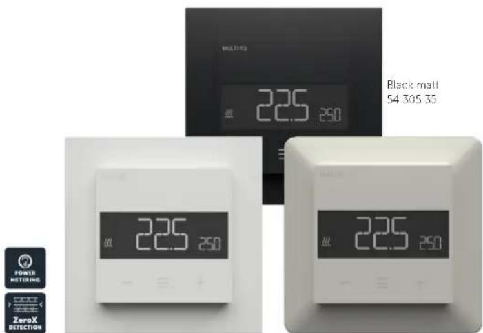
White RAL 9003
54 305 34
White RAL 9010
54 305 33
TABLE OF CONTENTS
- Introduction
- Quick Start
- Installation
- Connections
- Factory reset
- Startup
- Principles of regulation
- Local settings menu
- Display menu structure
- Temperature shown in display
- Standby and main screen
- KWh value in menu
- Size of load
- Choice of sensor
- Selecting sensor value
- Calibration
- Brightness
- Display on/off
- Display icons
- Child lock
- Open window detection
- Error codes
- Safety features
- Thermostat setpoint
- Thermostat mode
- Thermostat dimensions
- Thermostat controls
- Chart - Display menu structure Product info
1. INTRODUCTION
Multireg6 is an electronic thermostat designed for electrical heating. The thermostat has a user friendly interface that can be controlled from the buttons on the front.
Multireg6 has 3 modes; Heat - Cool and Eco.
The thermostat fits in standard European junction boxes and may be used with most System 55 frames. It has a sturdy metal frame for secure fastening on the junction box. The thermostat has one built-in room temperature sensor. Two additional external temperature sensors may also be connected.
The product has implemented ZeroX technology. This technology makes sure the relay switches at 0V when turning on and off. With this technology the thermostat will have a much longer lifetime.
Multireg6 has power metering which allows the user to see the total accumulated energy consumption in kWh.
The thermostat can withstand a load of max 16A/3600W at 230VAC. We recommend a contactor for loads above 13A.
2. QUICK START
- Switch off the mains voltage (turn off the fuse).
- Open the junction box.
- Connect according to the wiring diagram as shown in Chapter "Connections".
- After verifying the connections, switch on the mains voltage.
3. INSTALLATION
Installation must be done by a qualified electrician in accordance with national building codes. Before installation, disconnect the power to the device from the mains. During installation of the device, power to the device must be disconnected AT ALL TIMES!
The product allows for wiring of cables with a cross section of up to 1x2.5mm ^2 .
4. CONNECTIONS
Max tightening torque for terminal screws: 2Nm.
If the cable used has multiple strands using a end sleeve is advised.
To access the terminal screws, hold the sides of the display and gently pull outwards to detach the front piece.
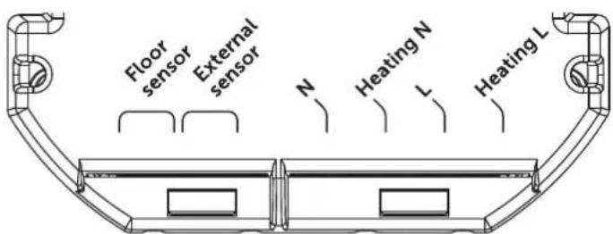
Floor sensor NTC type 6.8, 10, 12, 15, 22, 33, 47 or 100kΩ. Default 10kΩ.
External sensor NTC type 6.8, 10, 12, 15, 22, 33, 47 or 100kΩ. Default 10kΩ.
N Power connection (Neutral) 230VAC.
Heating N Heating cable N connection.
L Power connection (Live) 230VAC.
Heating L Heating cable L connection.
Next, position the thermostat and mount it into the junction box using 2 screws. Position the thermostat front over the part mounted in the junction box, then carefully press the front until it clicks into place. In order to get power metering values, the load needs to be connected to both heating L + N.
5. FACTORY RESET
Enter the menu by holding the Center button for about 5 seconds, navigate in the menu with the "+" button til you see "FACT". Press the Center button until you see "-- --" blinking in the display, then hold for about 5 seconds to perform a reset. You may also initiate a reset by holding the Right and Center buttons for 60 seconds.
When either of these procedures has been performed, the thermostat will perform a complete factory reset. The device will display "RES" for 5 seconds while performing a factory reset. When "RES" is no longer displayed, the thermostat has been reset.
6. STARTUP
After powering up the device for the first time, all parameters will have default settings and the thermostat will start by asking which sensor mode should be used.
7. PRINCIPLES OF REGULATION
The thermostat uses temperature readings retrieved from the internal sensor and/or from external wired sensors to regulate the temperature. The thermostat will regulate the temperature using hysteresis or PWM, based on the setpoint temperature.
7.1 Hysteresis
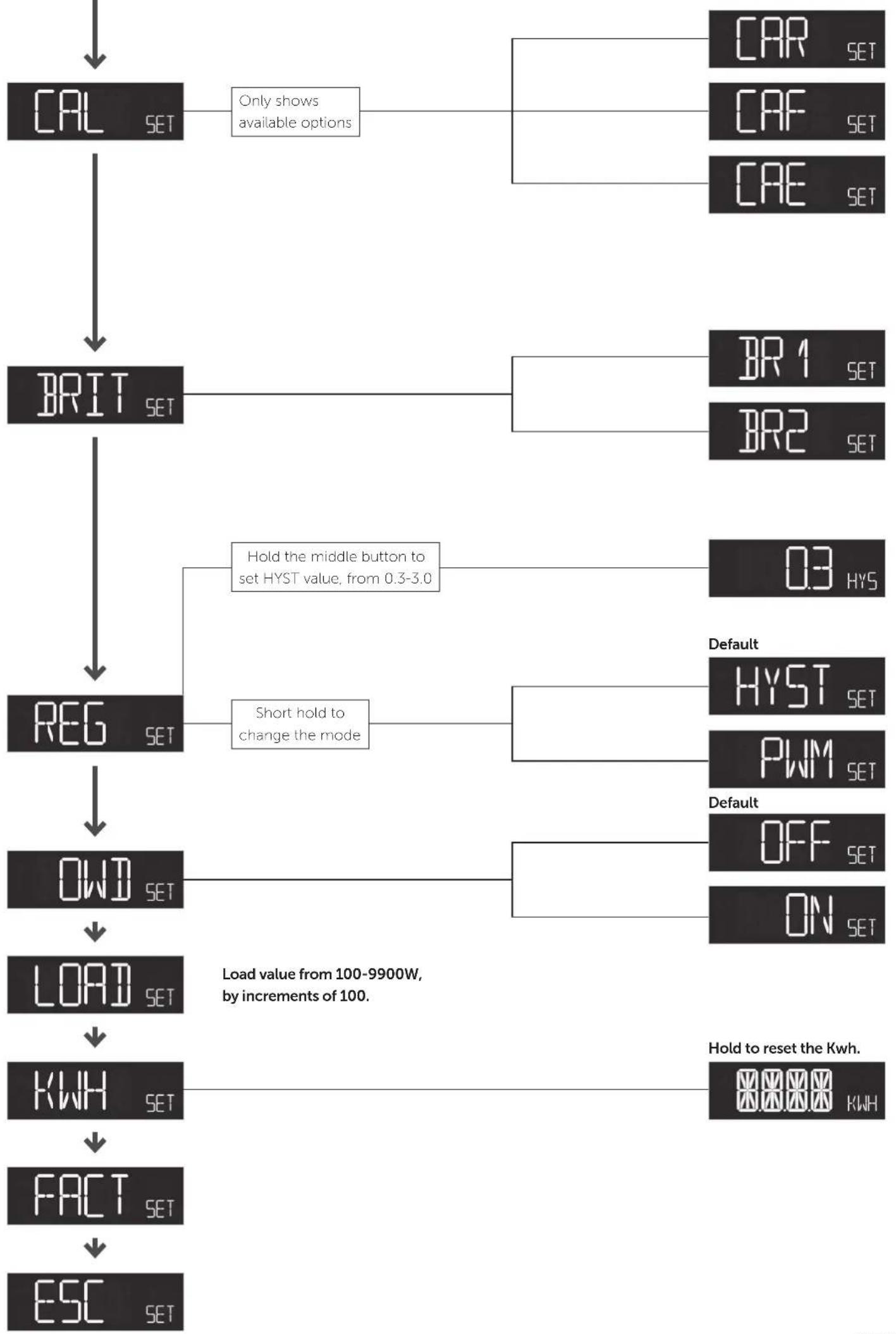
Hysteresis will turn on and off the load based on the hysteresis value in comparison to the setpoint. You can make changes to the thermostat hysteresis. It may be changed by entering the local settings menu and holding the Center button for 2 seconds when "REG" is displayed. Here you can choose values between 0.3 and 3.0. The default setting is 0.5°C. When using waterbased heating we recommend a hysteresis of 1.0°C.
7.2 Pulse-width modulation PWM
With PWM regulation enabled, the thermostat will regulate based on duty cycles. The thermostat is turned on and off in percentage intervals of the cycle. The amount of time the relay will be on is based on how far the measured temperature is from the setpoint.
To enter the settings menu, hold the Center button for 5 seconds. The display will display "OFF". You are now in the settings menu. While in the settings menu, "SET" will be displayed in the bottom right of the display. You can now scroll up and down using the Left and Right buttons. Some options have submenus. To navigate the submenus, press the Center button once to enter or exit the submenu. Press the Left and Right buttons to find your desired value and hold the Center button for 2 seconds to confirm your selection. "STOR" will appear to indicate settings are stored.
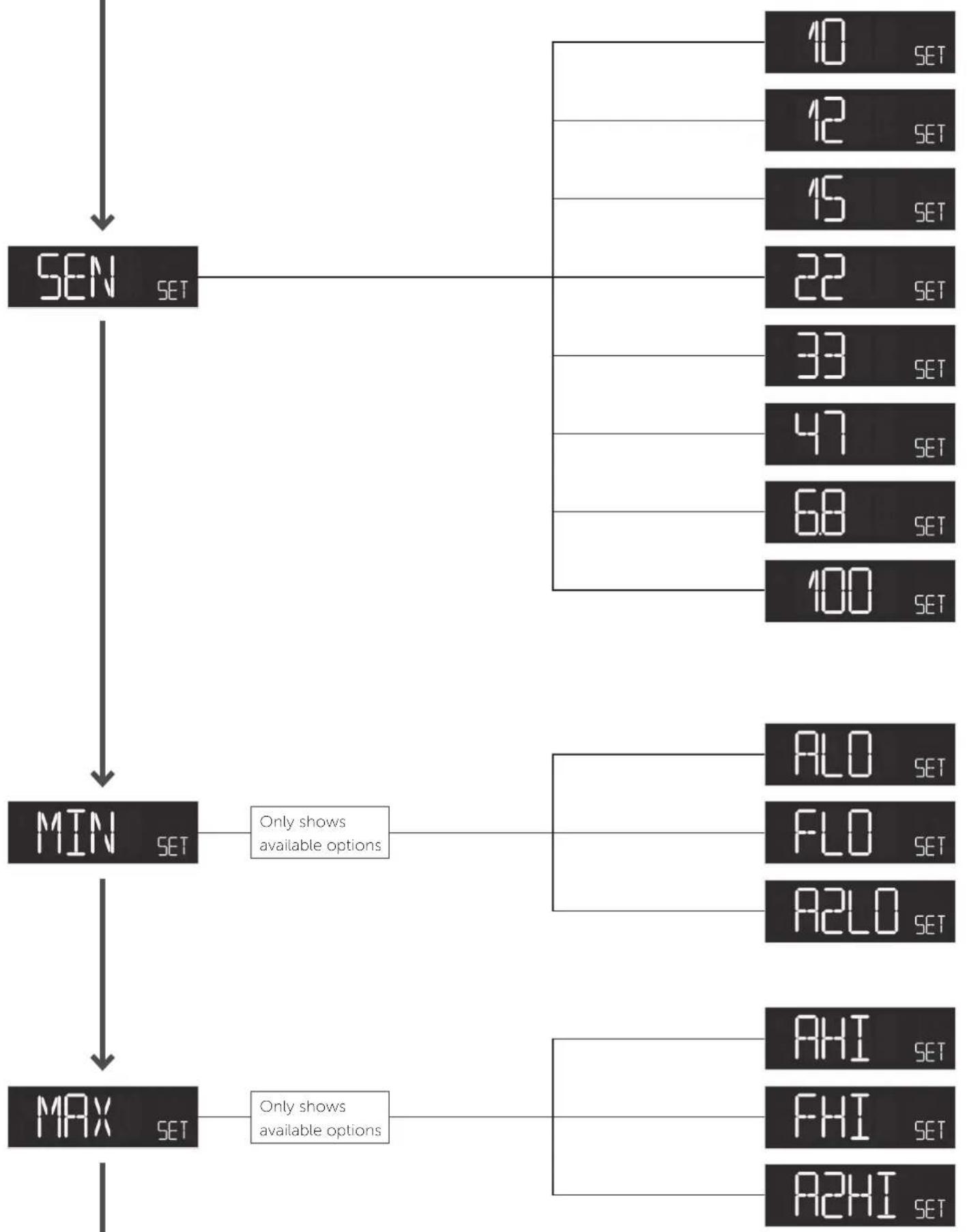
9. DISPLAY MENU STRUCTURE
See flowchart at the end of this manual.
10. TEMPERATURE SHOWN IN DISPLAY
By default, the temperature shown in the display while in standby state is the setpoint. This may be changed by entering the local settings menu and holding the Center button for 2 seconds when "MODE" is displayed. You can choose between "SETT" and "RELT". "SETT" is the Setpoint temperature and "RELT" is the real-time temperature.
11. STANDBY AND MAIN SCREEN
When the thermostat remains untouched for a while, it will automatically go to the standby screen. The standby will by default show the setpoint temperature. By pressing any button once, you will see the measured temperature. By pressing the Left or Right button multiple times, you will change the setpoint.
12. KWH VALUE IN MENU
The device supports power metering to give insight into the power consumption of the heating. The total consumption of the device can be seen in the system from the "kWh" menu option. The total consumption data can be reset by holding the Center button while in the kWh menu.
13. SIZE OF LOAD
In the "load" menu, the load value can be set manually if the load is not directly connected to the thermostat. The load size can be adjusted in 100W increments up to 9900W.
14. CHOICE OF SENSOR
The thermostat has multiple sensors and sensor modes. This lets you configure the thermostat to work correctly in most installations. The sensors and modes may be selected from the local settings menu ("OPER").
Available temperature sensors:
F Floor sensor
A Internal room sensor
AF Internal room sensor + Floor sensor
A2 External room sensor
A2F External room sensor + Floor sensor
PWER Power regulator mode (no sensor used)
NOTE: Some types of floor require that a floor sensor is connected in order to limit the floor temperature to a maximum of 27^ C (check the manual from the floor manufacturer). When the thermostat is used in (AF or A2F) the floor limiter FHI is automatically set to 27^ C. When using any other sensor type (A, F or A2) the minimum and maximum limits are 5^ C and 40^ C respectively.
15. SELECTING SENSOR VALUE
The thermostat allows the selection of multiple different resistance values of an NTC sensor and can be selected using the local settings "SEN". The supported sensor values are as follows: 6.8, 10, 12, 15, 22, 33, 47 or 100KΩ.
The factory default value is 10kΩ. When connecting both the floor sensor and the external sensor, make sure to use sensors with the same Ohm value.
16. CALIBRATION
If the temperature sensor readout is not correct, you can make minor changes to the temperature readout. The temperature readings can be calibrated by ±6^ . The temperature calibration can be performed from the menu using CAR, CAE and CAF. The adjusted value will be displayed indicating what the thermostat uses for regulation.
| SENSOR TYPE | IN MENU STRUCTURE |
| Internal sensor CAR | |
| External sensor CAE | |
| Floor sensor CAF |
17. BRIGHTNESS
Using the menu choices "BR1" and "BR2", the brightness of the display in Active and Standby state can be changed respectively.
18. DISPLAY ON/OFF (DON/DOFF)
The thermostat has a display ON/OFF function which decides whether the display should turn completely off when in Standby. To enable/disable this function, hold the Left and Center buttons for 10 seconds. The display will show "DOFF" when the function is activated and "DON" when the function is disabled. When operating any button, the display will light up.
19. DISPLAY ICONS
| ICON | DESCRIPTION |
| This icon will be displayed while the relay is on and the thermostat is in either Heating or Eco mode. | |
| This icon will be displayed while the relay is on and the thermostat is in Cooling mode. |
20.CHILD LOCK
Child lock is a function for disabling the buttons from the display locally. It will show "LOCK" when attempting to operate it while the function is enabled. To enable or disable the function, hold the Left and Right buttons for 10 seconds. Enabling the function will show "LOCK" in the display, disabling the function will show "OPEN".
21. OPEN WINDOW DETECTION OWD
Open Window Detection (OWD) is a function which will reduce the thermostat setpoint on detection of an open window. This happens when the temperature sensor registers a rapid temperature drop.
When OWD is active, the setpoint is reduced to 5^ C in order not to waste energy. OWD will automatically be cancelled if OWD has been active for more than 1 hour, or if the temperature increases by 3^ C. OWD can also be cancelled manually by increasing/decreasing the setpoint with the Left and Right buttons.
By default, OWD is not enabled. The feature may be enabled by selecting "OWD" from the menu. Choose between options "OFF" and "ON".
22. ERROR CODES
Err1 Internal error. Most probably a faulty unit. Replace unit.
Err3 Internal error. Most probably a faulty unit. Replace unit.
Err4 Floor sensor error. You have chosen F, AF or A2F sensor mode without having a floor sensor connected, or the sensor may be damaged.
Err5 External sensor error. You have chosen A2 or A2F, and there are no external sensors installed or the sensor may be damaged.
Err6 Overheating. Contact your electrician.
Err7 Overload. Contact your electrician.
23. SAFETY FEATURES
The device has safety features to ensure safe operation and warn the user of any faults/unexpected behavior. The device has an Overheat and Overload function. If the thermostat registers an Overheat or Overload incident, the thermostat will switch off and an error code will appear in the display.
23.1 Overheating
The device features internal temperature sensors to prevent the device from overheating. The device will attempt to turn off the relay and warn the user.
When overheating is detected, the device will:
- Turn off the relay.
- Display Err6 in the display.
23.2 Overload
The device features a 16A overload protection. The overload is triggered if there is a current draw of more than 16A.
When overload is detected, the device will:
- Turn off the relay.
- Display Err7 in the display.
23.3 Sensor failure
The device has the ability to detect when there is no sensor connected, or if the sensor is broken or otherwise defective, causing an open circuit.
When the device detects the sensor error, the device will:
- Turn off the relay.
- Display an error in the display, changes based on which sensor is not connected/faulty.
To clear the "Sensor not connected" error the device has to be disconnected from the mains, and the wiring and sensor(s) need to be checked. When the fault is resolved the mains can be reconnected and the device will function normally again.
24. THERMOSTAT SETPOINT
The device supports 3 setpoints: Heating, Cooling and ECO. Supported setpoints are from 5°C - 40°C with 0.5°C increments.
25. THERMOSTAT MODE
It is possible to change the operating mode of the thermostat in the Mode menu. The accessible operating modes are:
OFF Thermostat regulation and display are deactivated.
Heating Mode Thermostat regulation is active.
Cooling Mode Thermostat regulation is inverted.
ECO Mode Thermostat regulation is active with a separate setpoint from Heating Mode.
- THERMOSTAT DIMENSIONS
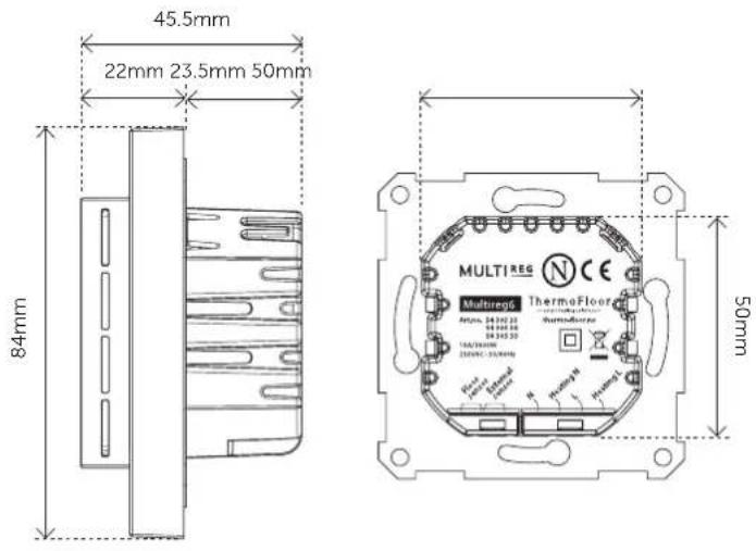
- THERMOSTAT CONTROLS
| ICON | DESCRIPTION |
| — | Previous.Decrease set temperature. |
| ≡ | Menu confirm.Menu enable. |
| + | Next.Increase set temperature. |
28. CHART - DISPLAY MENU STRUCTURE
Hold the middle button for 5 seconds to enter menu.
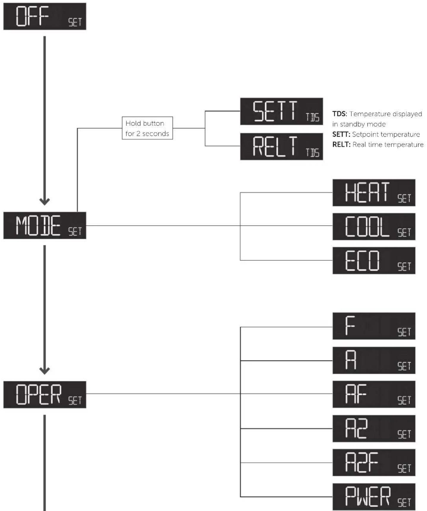
flowchart
graph TD
    A["OFF SET"] --> B["MODE SET"]
    B --> C["OPER SET"]
    B --> D["Hold button for 2 seconds"]
    D --> E["SETT TDS"]
    D --> F["RELT TDS"]
    E --> G["TDS: Temperature displayed in standby mode"]
    F --> H["SETT: Setpoint temperature"]
    F --> I["RELT: Real time temperature"]
    B --> J["HEAT SET"]
    B --> K["COOL SET"]
    B --> L["ECO SET"]
    C --> M["F SET"]
    C --> N["A SET"]
    C --> O["AF SET"]
    C --> P["A2 SET"]
    C --> Q["A2F SET"]
    C --> R["PWER SET"]
flowchart
graph TD
    A["SEN SET"] --> B["MIN SET"]
    A --> C["MAX SET"]
    B --> D["Only shows available options"]
    C --> E["Only shows available options"]
    D --> F["10 SET"]
    D --> G["12 SET"]
    D --> H["15 SET"]
    D --> I["22 SET"]
    D --> J["33 SET"]
    D --> K["47 SET"]
    D --> L["68 SET"]
    D --> M["100 SET"]
    E --> N["ALO SET"]
    E --> O["FLO SET"]
    E --> P["A2LO SET"]
    E --> Q["AHI SET"]
    E --> R["FHI SET"]
    E --> S["A2HI SET"]
flowchart
graph TD
    A["CAL SET"] --> B["Only shows available options"]
    B --> C["CAR SET"]
    B --> D["CAF SET"]
    B --> E["CAE SET"]
    A --> F["BRIT SET"]
    F --> G["BR1 SET"]
    F --> H["BR2 SET"]
    F --> I["REG SET"]
    I --> J["Hold the middle button to set HYST value, from 0.3-3.0"]
    I --> K["Short hold to change the mode"]
    K --> L["Default HYST SET"]
    K --> M["Default PWM SET"]
    I --> N["OWD SET"]
    N --> O["Load value from 100-9900W, by increments of 100."]
    N --> P["KWH SET"]
    P --> Q["Hold to reset the Kwh."]
    P --> R["FACT SET"]
    R --> S["ESC SET"]
28.1 Error messages in display
| ERR 1 |
| ERR3 |
| ERR4 |
| ERR5 |
| ERR6 |
| ERR7 |
28.2 General display messages
| LOCK |
| OPEN |
| DON |
| DOFF |
| 88880WD |
| STOR |
DISPOSAL GUIDELINES
Do not dispose of electrical appliances as unsorted municipal waste, use separate collection facilities. Contact your local government for information regarding the collection systems available. If electrical appliances are disposed of in landfills or dumps, hazardous substances can leak into the groundwater and go into the food chain, deruging food and well-being.
We have designed this product in accordance with our strict quality requirements (ISO 9001) and environmental requirements (ISO 14001). All electrical installations must be carried out, by an authorized electrical installer. The product must be installed in accordance with our installers manual are national building codes. Any wrongful installation, misuse or damage to the product is not covered under warranty.
The micro-Floor AS cannot be held liable for any type of errors or irritances in our product information. Product specifications may change without further notice.
PRODUCT INFO Multireg6
FEATURES
- Internal room sensor
• External room sensor (wired by cable) - Floor sensor
• Power regulator
• Temperature limiter
• 3 modes; Heat, Cool and Eco
• Active power metering - Hysteresis/PWM
- Relay status icon
- Adjustable display brightness
- Single pole switch
- Lock mode/child lock
• Temperature calibration - Open window detection
- ZeroX detection
TECHNICAL DATA
Rated voltage 230VAC 50Hz
Max. load 3600W (resistive load)
Contactor recommended for loads above 13A
Max. current 16A
Power consumption <2.0W
Power regulator Time cycle 0 to 30 min
Ambient temperature 5°C to 40°C
Temperature range 5°C to 40°C
Storage temperature -30°C to 70°C
Hysteresis 0.3°C to 3.0°C (default 0.5°C)
Humidity 10% to 85% RH
Compatible with NTC-
sensors with values 6.8, 10, 12, 15, 22, 33, 47 or 100kΩ @ 25°C
Screw terminal Max. 2.5mm ^4 2Nm
IP Code IP 21
Size 84 x 84 x 45mm
Approvals CE, Nemko
MAINTENANCE
The device is maintenance-free. Indoor use only.
ThermoFloor
— smart heating solutions —
Thermo-Floor AS | Mattisrudsvingen 19, 2827 HUNNDALEN, NORWAY
Phone: +47 61 18 77 77 | post@thermo-floor.no - thermo-floor.no
- TABLE OF CONTENTS
- INTRODUCTION
- QUICK START
- INSTALLATION
- CONNECTIONS
- FACTORY RESET
- STARTUP
- PRINCIPLES OF REGULATION
- Hysteresis
- Pulse-width modulation PWM
- DISPLAY MENU STRUCTURE
- TEMPERATURE SHOWN IN DISPLAY
- STANDBY AND MAIN SCREEN
- KWH VALUE IN MENU
- SIZE OF LOAD
- CHOICE OF SENSOR
- SELECTING SENSOR VALUE
- CALIBRATION
- BRIGHTNESS
- DISPLAY ON/OFF (DON/DOFF)
- DISPLAY ICONS
- 20.CHILD LOCK
- OPEN WINDOW DETECTION OWD
- ERROR CODES
- SAFETY FEATURES
- Overheating
- Overload
- Sensor failure
- THERMOSTAT SETPOINT
- THERMOSTAT MODE
- CHART - DISPLAY MENU STRUCTURE
- DISPOSAL GUIDELINES
- PRODUCT INFO Multireg6
- FEATURES
- TECHNICAL DATA
- MAINTENANCE
Brand : Heatit
Model : MULTIREG6
Category : Thermostat