
DA 6A - Audio/video switch Extron - Free user manual and instructions
Find the device manual for free DA 6A Extron in PDF.


| Product Type | Audio Distribution Amplifier |
| Model | DA 6A |
| Number of Inputs | 1 stereo audio input (balanced/unbalanced, captive screw) |
| Number of Outputs | 6 stereo audio outputs (balanced/unbalanced, captive screw) |
| Audio Gain | Adjustable via internal jumpers: -6 dB, 0 dB, +6 dB per channel |
| Frequency Response | 20 Hz to 20 kHz, ±0.08 dB |
| THD + Noise | 0.03% @ 1 kHz at nominal level |
| Signal-to-Noise Ratio | >90 dB, unbalanced, at maximum output (unweighted) |
| Stereo Channel Separation | >80 dB @ 1 kHz; >60 dB @ 20 kHz |
| Common Mode Rejection Ratio (CMRR) | >75 dB @ 20 Hz to 20 kHz |
| Input Impedance | 18 kΩ unbalanced, 24 kΩ balanced, DC coupled |
| Output Impedance | 50 Ω unbalanced, 100 Ω balanced |
| Maximum Output Level (Hi-Z) | +24 dBu balanced at 1% THD+N |
| Power Supply | Internal, 100 VAC to 240 VAC, 50/60 Hz, 8 watts |
| Enclosure Dimensions | 1.7" H x 8.7" W x 6.0" D (1U high, half rack wide) |
| Product Weight | 2 lbs (0.9 kg) |
| Mounting Options | Rack shelf, under-desk, through-desk (optional kits) |
| Cooling | Convection, unvented |
| Regulatory Compliance | CE, FCC Class A, VCCI, AS/NZS, ICES, UL, CUL |
| Warranty | 3 years parts and labor |
| Included Accessories | IEC power cord, 7 captive screw connectors (5-pole), Tweeker, rubber feet, user manual |
| Optional Accessories | RSU 129 rack shelf, RSB 129 rack shelf, MBU 125 under-desk mount, MBU 129 through-desk mount |
Frequently Asked Questions - DA 6A Extron
User questions about DA 6A Extron
0 question about this device. Answer the ones you know or ask your own.
Ask a new question about this device
Download the instructions for your Audio/video switch in PDF format for free! Find your manual DA 6A - Extron and take your electronic device back in hand. On this page are published all the documents necessary for the use of your device. DA 6A by Extron.
USER MANUAL DA 6A Extron
Extron. Electronics INTERFACING, SWITCHING AND DISTRIBUTION

User's Manual
natural_image
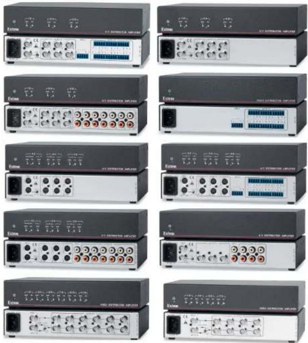
Collection of multiple electronic equipment units with various ports and connectors (no visible text or labels)Audio/Video Distribution Amplifiers

www.cxtron.com
Eaton Electronics, USA
1230 South Litter Steel
Methem, CA 9205
300.6319678 714.491.503
FAX 714.491.1517
Extron Electronics, Europe
Beldscherinweg 60
3821 /H Amersfort, The Netherlands
1000.3907.6873 +31.32.459.4040
FAX:31.33.453.4050
Extron Electronics, Asia
135 Joo Seng Rd. 304-01
PM Industrial Bkg., Singapore 368360
(200.7339.0768 + 65.6303.4400
FAX +85.8203.4864
Extron Electronics, Japan
Kyodo Building, 16 kambacho
Chiyode-ku, Tokyo 102-0082
JAN
DA 6V EQ
DA 6AV EQ
DA 6AV RCA EQ
DA 6SV EQ
DA 6SVA EQ
DA 6SVA RCA EQ
DA 6A
DA 8V/4V Dual EQ
DA 12V/6V Dual EQ
DA 3AV RCA
68-977-01, Rev. B
09 07
Precautions
Safety Instructions • English

This symbol is intended to alert the user of important operating and maintenance (servicing) instructions in the literature provided with the equipment.

This symbol is intended to alert the user of the presence of uninsulated dangerous voltage within the product's enclosure that may present a risk of electric shock.
Caution
Read instructions • Read and understand all safety and operating instruments before using the equipment.
Retain Instructions + the safety instructors should be kept for future
Follow Warnings • Follow all warnings and awareness posted on the seasonal or in the year introduction.
Avoid Attachments • Do not use tools or attachments that are not recommended by the environment to choose from work
We believe that by the equivalent investment or strategy they may be rational.
Andes in your plan, 24.19.18 in the Nitzelschutzschutz
Power sources. This equipment should be operated only from the power source
the first of the 2013. The approach is to be a 1500-wolfe, all power system with a grounded (neutral) combiner. The third (grounding) put a safety mixture, do not attempt to bypass or displace it.
Power disconnection • To remote power from the equipment safety, remote all
power bonds from the heat of the equipment, or the cockpit p detachth e) or from the power source receptacle (wall plot).
Power coal protection *Fores cars should be cooled so that they are not likely to be expected on or powered by items passed upon or against them.
Servicing • Referral servicing to qualified service personnel. There are no use
The exercise part is made to prepare the line of sheet do not imagine to serve the equivalent yourself (boxerior opening or rearing, except they expect you to undergo will and other things).
Slots and openings of the equipment has slots or holes in its enclosure, these are provided to cover, backshoring of concrete ingotainment tools. Then opening must never be blocked by other objects.
Tilium battery • There is a danger of splenic: P. Kowey is heteromethyriplized
maples 1, only with the state of equilibria (ept reconstituted by the transatlantism. Plans of used talkers or assent to the manufacturer
instructions
Avertissement
Institute in the following manner is not to be taken by the
- 1. In fact, the following is a result of the
The following table is in English:
Extron Electronics warrants this product against defects in materials and workmanship for a period of three years from the date of purchase. In the event of malfunction during the warranty period attributable directly to faulty workmanship and/or materials, Extron Electronics will, at its option, repair or replace said products or components, to whatever extent it shall deem necessary to restore said product to proper operating condition, provided that it is returned within the warranty period, with proof of purchase and description of malfunction to:
USA, Canada, South America, Europe, Africa, and the Middle East and Central America:
Extron Electronics Beeldschermweg 6C
1001 East Ball Road 3821 AH Amersfoort
Anaheim, CA 92805, USA The Netherlands
Extron Electronics, Europe
Asia: Japan:
Extron Electronics, Asia Extron Electronics, Japan
135 Too Seng Road, #04-01 Kyodo Building
PM Industrial Bldg. 16 Ichibancho
This Limited Warranty does not apply if the fault has been caused by misuse, improper handling care, electrical or mechanical abuse, abnormal operating conditions or non-Extron authorized modification to the product.
If it has been determined that the product is defective, please call Extron and ask for an Applications Engineer at (714) 491-1500 (USA), 31.33.453.4040 (Europe), 65.6383.4400 (Asia), or 81.3.3511.7655 (Japan) to receive an RA# (Return Authorization number). This will begin the repair process as quickly as possible.
Units must be returned insured, with shipping charges prepaid. If not insured, you assume the risk of loss or damage during shipment. Returned units must include the serial number and a description of the problem, as well as the name of the person to contact in case there are any questions.
Extron Electronics makes no further warranties either expressed or implied with respect to the product and its quality, performance, merchantability, or fitness for any particular use. In no event will Extron Electronics be liable for direct, indirect, or consequential damages resulting from any defect in this product even if Extron Electronics has been advised of such damage.
Please note that laws vary from state to state and country to country, and that some provisions of this warranty may not apply to you.
安全须知 · 中文

This equipment has been tested and found to comply with the limits for a Class A digital device, pursuant to part 15 of the FCC Rules. Operation is subject to the following two conditions: (1) this device may not cause harmful interference, and (2) this device must accept any interference received, including interference that may cause undesired operation. The Class A limits are designed to provide reasonable protection against harmful interference when the equipment is operated in a commercial environment. This equipment generates, uses, and can radiate radio frequency energy and, if not installed and used in accordance with the instruction manual, may cause harmful interference to radio communications. Operation of this equipment in a residential area is likely to cause harmful interference, in which case the user will be required to correct the interference at his own expense.
NOTE
This unit was tested with shielded cables on the peripheral devices. Shielded cables must be used with the unit to ensure compliance with FCC emissions limits.
This page was intentionally left blank.
Quick Start Guide — DA AV EQ Series
To install and set up a DA AV EQ Series distribution amplifier, follow these steps:
Step 1
Turn all of the equipment off and disconnect it from the power source.
Step 2
Mount the DA AV EQ on a rack shelf, under a desktop or podium, or through a desktop. See "Mounting the DA AV EQ Series" in chapter 2, "Installation and Rear Panel," for mounting procedures. See "Optional Accessories" in appendix A, "Specifications, Parts, and Accessories," for part numbers.
Step 3
Wire the audio captive screw connectors. For the models with captive screw connectors for audio input and output, follow the illustrations below to wire them.
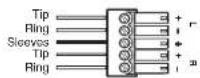
Balanced Stereo Input
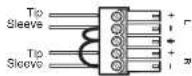
Unbalanced Stereo Input
Wiring the captive screw audio input connectors
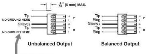
CAUTION
For unbalanced audio, connect both sleeves to the center contact ground. DO NOT connect the sleeves to the negative (-) contacts.
Do not tin the wires!
Wiring the captive screw audio output connectors
WARNING
Disconnect all power to the unit before wiring.
Quick Start Guide — DA AV EQ Series, cont'd
Step 4
Connect the cables of the input and output devices to the DA AV EQ, and power on all equipment.
- S-video devices are connected to 4-pin mini DIN connectors.
- Composite video devices are connected to BNC connectors.
Audio devices are connected to captive screw or RCA connectors.

Step 5
Adjust the potentiometers (pots) for the output cable lengths, if necessary.
- If using very short output cables, make sure that the potentiometers are in the unity gain position; that is, with the arrow on each pot pointing to the dot beside or above the pot.
If the pots are already in the unity gain position (factory default settings), DO NOT CHANGE THEM. If they are not in the unity gain position, rotate them into position, using an Extron Tweeker. The illustration below shows the pots for outputs 1 and 2 at the unity gain position.
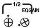
Composite Video Models
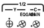
S-video Models
Potentiometers at unity gain setting
• If using long cables, follow these steps to adjust the pots:
a. Supply the Color Bars test signal to the input.
(Recommendation: Use an Extron VTG 300 Video Test Generator to generate the test signal.)
b. Adjust the Gain pot(s) for output pair 1 and 2 until the signal level at the far end is the same as the input (or the display shows the correct brightness and contrast).
c. Adjust the EQ pot for outputs 1 and 2 so that no overshoot or round front corners appear at the far end on the scope (or until you see a sharp picture with no smearing).
d. Repeat steps b and c for the rest of the outputs.
Table of Contents
Chapter 1 • Introduction ...... 1-1
About this Manual 1-2
About the DA AV EQ Series 1-2
Models 1-2
Features 1-3
Application diagrams 1-4
Chapter 2 • Installation and Rear Panel ...... 2-1
Mounting the DA AV EQ Series 2-2
Tabletop use 2-2
Rack mounting.... 2-2
UL rack mounting requirements 2-2
Rack mounting procedure 2-3
Furniture mounting 2-4
Through-desk mounting 2-6
Rear Panel Features and Cabling 2-7
Setting the Audio Output Gain 2-12
Chapter 3 • Front Panel Features and Operation ... 3-1
Front Panel Features 3-2
Gain and Equalization Controls 3-4
Settings for short cables 3-5
Adjusting for long cables 3-6
Adjusting with an oscilloscope 3-6
Adjusting without an oscilloscope 3-6
Appendix A • Specifications, Parts, and
Accessories A-1
Specifications A-2
Models A-6
Included Parts A-7
Optional Accessories....A-7
Cables A-8
All trademarks mentioned in this manual are the properties of their respective owners.
68-977-01 Rev. B
09 07
Table of Contents, cont'd

DA AV EQ Series
1 Chapter One
This page was intentionally left blank.
Introduction
About this Manual
About the DA AV EQ Series
Introduction
About this Manual
This manual provides information on the Extron DA AV EQ series of audio/video distribution amplifiers and discusses how to install and operate them.
The terms "DA," "amplifier," and "distribution amplifier" are used interchangeably to refer to any of the models in the DA AV EQ series.
About the DA AV EQ Series
The Extron DA AV EQ Series products are high-performance composite video or S-video distribution amplifiers with audio. Models with audio only and video only are also available. The DA AV EQ series amplifiers feature long cable drive capability and individual gain and equalization adjustments (for every two outputs) to optimize the picture for displays that are located at significantly different distances from the DA.
Models
The DA AV EQ Series consists of the following 10 models:
DA 6V EQ — One input, six outputs, composite video with equalization and gain controls
DA 6AV EQ — One input, six outputs, audio, and composite video with equalization and gain controls
DA 6AV RCA EQ — One input, six outputs, audio on RCA connectors, and composite video with equalization and gain controls
DA 6SV EQ — One input; six outputs; S-video with luma (Y) equalization control, and luma and chroma gain controls
DA 6SVA EQ — One input; six outputs; audio; and S-video with luma (Y) equalization control, and luma and chroma gain controls
DA 6SVA RCA EQ — One input; six outputs; audio on RCA connectors; and S-video with luma (Y) equalization control, and luma and chroma gain controls
DA 6A — One input, six outputs, audio only
DA 3AV RCA — One input, three outputs, audio on RCA connectors, and composite video
DA 12V/6V Dual EQ — Dual composite video DA that can function as either a 1-input, 12-output DA with one active loop-through, or two 1-input, 6-output DAs in one enclosure (no loop-through); equalization and gain controls
DA 8V/4V Dual EQ — Dual composite video DA that can function as either a 1-input, 8-output DA with one active loop-through or two 1-input, 4-output DAs in one enclosure (no loop-through); equalization and gain controls
Features
Equalization and gain control — Independent gain and equalization control for each two outputs provides more flexibility and more accurate cable compensation to drive different lengths of cables from different outputs. (S-video models have Y-only equalization, and Y and C gain controls.)
NOTE Outputs with similar lengths of cables should be paired in the same output group so that they can share the same gain and EQ setup.
Passive video loop-through — All models except DA 6A, DA 12V/6V Dual EQ, and DA 8V/4V Dual EQ feature a passive video loop-through channel with a 75 ohm impedance toggle switch, which provides for local monitoring and cascading to another distribution amplifier.
Power supply — An internal 100 VAC to 240 VAC, 50/60 Hz, autoswitchable power supply is provided on all models.
Enclosure — All models have a compact 1U, half rack enclosure, six inches in depth.
High bandwidth — Bandwidth of 150 MHz @ -3 dB for composite video and S-video maintains signal quality without picking up noise.
Rack and furniture mountability — All models can be mounted on a rack shelf, under a desk or podium, or through a desk or table top.
Introduction, cont'd
Application diagrams
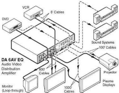
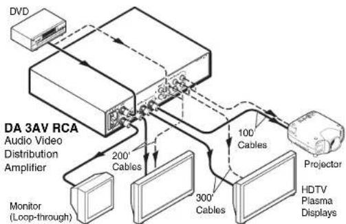
The connection diagrams below show examples of how devices may be connected to the DA AV EQ Series distribution amplifiers.
flowchart
graph TD
    A["VCR"] -->|6' Cables| B["DA 6AV EQ Audio Video Distribution Amplifier"]
    C["DVD"] --> B
    B --> D["800' Cables"]
    D --> E["Monitor (Loop-through)"]
    D --> F["1000' Cables"]
    F --> G["100' Cables"]
    G --> H["Sound Systems"]
    H --> I["Projector"]
    I --> J["Plasma Displays"]
    style B fill:#f9f,stroke:#333
    style D fill:#ccf,stroke:#333
    style F fill:#ccf,stroke:#333
    style G fill:#ccf,stroke:#333
    style H fill:#ccf,stroke:#333
    style I fill:#ccf,stroke:#333
    style J fill:#ccf,stroke:#333
Example of devices connected to a DA 6AV EQ
flowchart
graph TD
    A["DVD"] --> B["DA 3AV RCA Audio Video Distribution Amplifier"]
    B --> C["Monitor (Loop-through)"]
    B --> D["200' Cables"]
    B --> E["300' Cables"]
    B --> F["100' Cables"]
    F --> G["Projector"]
    G --> H["HDTV Plasma Displays"]
Example of devices connected to a DA 3AV RCA

DA AV EQ Series
2 Chapter Two
Installation and Rear Panel
Mounting the DA AV EQ Series
Rear Panel Features and Cabling
Setting the Audio Output Gain
Installation and Rear Panel
Mounting the DA AV EQ Series
The DA AV EQ distribution amplifiers can be set on a table; mounted on a rack shelf; or mounted through or under a desk, podium, or tabletop.
The following optional mounting kits are available for the DA AV EQ Series:
• RSB 126 1U, 6" deep basic rack shelf (part #60-604-10)
•RSU 126 1U, 6" deep universal rack shelf kit (part #60-190-10)
• RSB 129 1U, 9.5" deep basic rack shelf (part #60-604-01)
•RSU 129 1U, 9.5" deep universal rack shelf kit (part #60-190-01)
•MBU 125 under-desk mounting bracket kit (part #70-077-01)
- MBD 129 through-desk mounting bracket kit (part #70-077-02)
Tabletop use
Four self-adhesive rubber feet are included with the unit. For tabletop use, affix one foot at each corner of the bottom of the DA, and place the unit in the desired location.
Rack mounting
UL rack mounting requirements
The following Underwriters Laboratories (UL) requirements pertain to the safe installation of the equipment in a rack.
-
Elevated operating ambient temperature — If the equipment is installed in a closed or multi-unit rack assembly, the operating ambient temperature of the rack environment may be greater than room ambient temperature. Therefore, install the equipment in an environment compatible with the maximum ambient temperature (Tma = +113 °F, +45 °C) specified by Extron.
-
Reduced air flow — Install the equipment in a rack so that the amount of air flow required for safe operation of the equipment is not compromised.
-
Mechanical loading — Mount the equipment in the rack so that a hazardous condition is not achieved due to uneven mechanical loading.
-
Circuit overloading — Connect the equipment to the supply circuit and consider the effect that circuit overloading might have on overcurrent protection and supply wiring. Appropriate consideration of equipment nameplate ratings should be used when addressing this concern.
-
Reliable earthing (grounding) — Maintain reliable grounding of rack-mounted equipment. Pay particular attention to supply connections other than direct connections to the branch circuit (e.g., use of power strips).
Rack mounting procedure
To mount the distribution amplifier on a 6" deep or 9.5" deep rack shelf,
-
If rubber feet were previously attached to the bottom of the unit, remove them.
-
Mount the unit on the rack shelf, using two 4-40 x 3/16" screws in opposite (diagonal) corners to secure it.
-
Install blank panel(s) or other unit(s) on the rack shelf.
-
Attach the rack shelf to the rack using the supplied bolts.
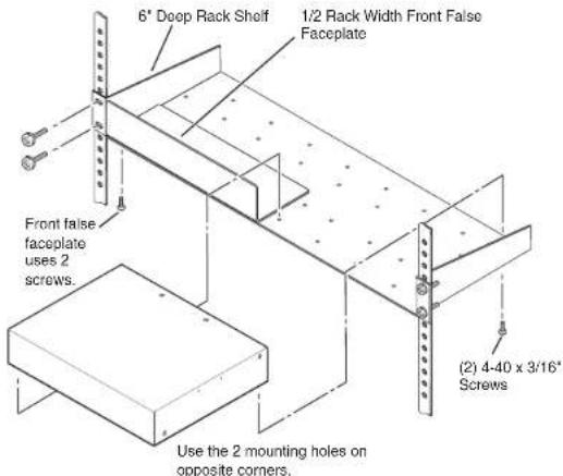
Mounting a DA AV EQ on a 6" deep rack shelf
Installation and Rear Panel, cont'd
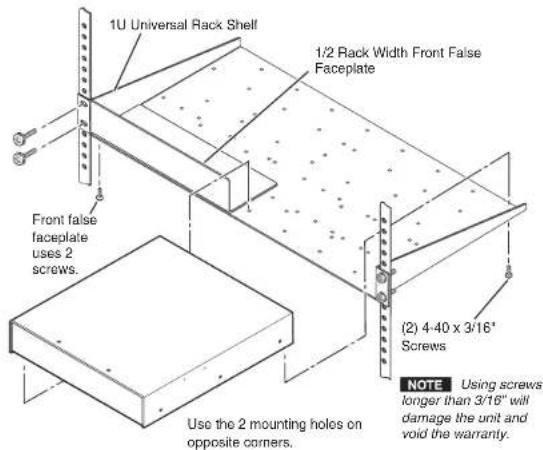
Mounting a DA AV EQ on a 9.5" deep rack shelf
Furniture mounting
Furniture-mount the DA AV EQ under a desk or shelf using the optional mounting kit (part #70-077-01), as illustrated below.
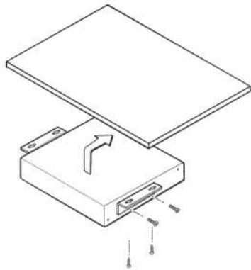
natural_image
Technical line drawing of a mechanical assembly with a flat plate and a rectangular base, showing internal components and a curved arrow indicating motion (no text or symbols)Under-desk mounting the DA AV EQ
To mount the DA AV EQ under a desk, podium, or table top,
1. If rubber feet were previously attached to the bottom of the unit, remove them.
2. Remove the two screws from one side of the unit. Retain the screws for possible later reassembly.
3. Attach one bracket to the side of the unit, using the provided machine screws.
4. Repeat steps 2 and 3 on the other side of the unit.
5. Hold the DA with the attached brackets against the underside of the table or other furniture. On the mounting surface, mark the location of the bracket's screw holes.
6. Drill pilot holes 1/4" (6.4 mm) deep and 3/32" (2 mm) in diameter into the table or desk top at the marked screw locations. The holes should be drilled from the underside or inside (concealed side) of the furniture where the amplifier will be located.
7. Insert #8 wood screws into the four pilot holes. Tighten each screw into the mounting surface until slightly less than 1/4" of the screw head protrudes.
8. Align the mounting screws with the slots in the brackets and place the unit against the surface, with the screws through the bracket slots.
9. Slide the unit slightly forward or back, then tighten all four screws to secure it in place.
Installation and Rear Panel, cont'd
Through-desk mounting
Mount the DA AV EQ through a desk or table, using the optional through-desk mounting kit (part #70-077-02).
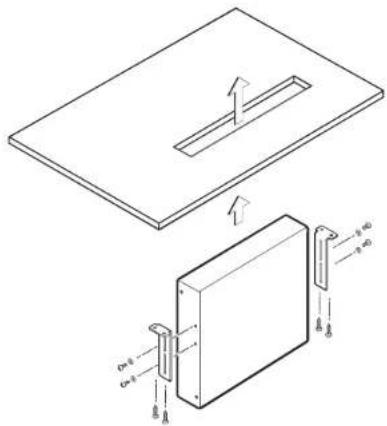
Through-desk mounting the DA AV EQ
- Mark the opening through which the unit will be mounted — approximately 1.8" by 8.9" (4.6 cm by 22.6 cm).
- Cut out the material from the installation area with a jigsaw.
- Drill pilot holes 1/4" (6.4 mm) deep and 3/32" (2 mm) in diameter in the desk or table at the locations of the mounting bracket screws. The holes should be drilled from the underside or inside (concealed side) of the furniture where the amplifier will be located.
- Using the four provided wood screws, attach the brackets to the mounting surface.
- Slide the unit up and down or back and forth in the mounting brackets until the face of the DA is at the desired height. Tighten the screws that secure the bracket in place. If the screws are inaccessible to a screwdriver.
a. Mark the location of the brackets relative to the screws.
b. Remove the DA from inside the furniture.
c. Tighten the screws.
d. Replace the DA inside the surface (repeat step 4).
Rear Panel Features and Cabling
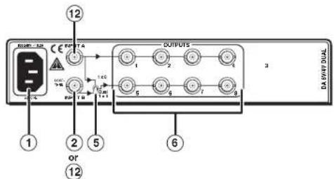
The following diagrams show the rear panel configurations of the 10 models in the DA AV EQ series.
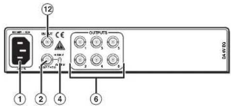
DA 6V EQ rear panel
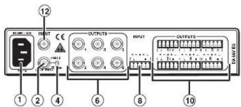
DA 6AV EQ rear panel
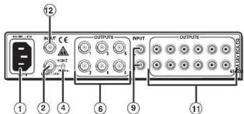
DA 6AV RCA EQ rear panel
Installation and Rear Panel, cont'd
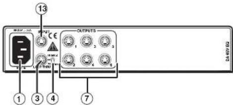
DA 6SV EQ rear panel
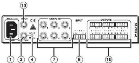
DA 6SVA EQ rear panel
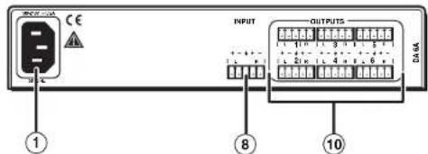
DA 6A rear panel
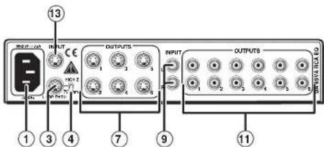
DA 6SVA RCA EQ rear panel
flowchart
graph TD
    A["Input 1"] --> B["B"]
    C["Input 2"] --> D["U"]
    E["Input 3"] --> F["OUTPUT"]
    G["Input 4"] --> H["OUTPUT"]
    I["Input 5"] --> J["OUTPUT"]
    K["Input 6"] --> L["OUTPUT"]
    M["Output 1"] --> N["OUTPUT"]
    O["Output 2"] --> P["OUTPUT"]
    Q["Output 3"] --> R["OUTPUT"]
    S["Output 4"] --> T["OUTPUT"]
    U["Output 5"] --> V["OUTPUT"]
    W["Output 6"] --> X["OUTPUT"]
    Y["Output 7"] --> Z["OUTPUT"]
    AA["Output 8"] --> AB["OUTPUT"]
    AC["Output 9"] --> AD["OUTPUT"]
    AE["Output 10"] --> AF["OUTPUT"]
DA 8V/4V Dual EQ rear panel
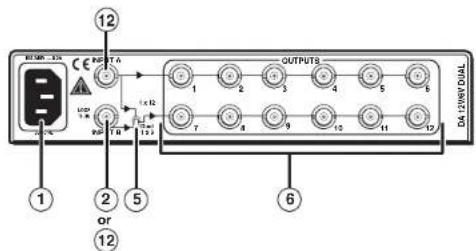
DA 12V/6V Dual EQ rear panel
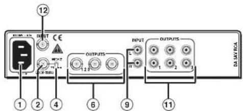
DA 3AV RCA rear panel
① AC power connector — Plug a standard IEC power cord into this male connector to connect the distribution amplifier to a 100 to 240 VAC, 50 Hz or 60 Hz power source.
Installation and Rear Panel, cont'd
② Passive Loop-Thru connector (composite video) — (All models except DA 6A and the three S-video models) Connect a monitor to this female BNC video loop-through connector.
NOTE This connector functions as an input on the DA 12V/6V and 8V/4V Dual EQ models when they are operating in Dual mode.
③ Passive Loop-Thru connector (S-video) — (DA 6SV EQ, DA 6SVA EQ, and DA 6SVA RCA EQ only) Connect a monitor to this female 4-pin mini DIN video loop-through connector.
④ Termination toggle switch — (All models except DA 6A, DA 12V/6V Dual EQ, and DA 8V/4V Dual EQ) Set this switch to High Z (up) if a monitor is plugged into the passive Loop-Thru connector. Set the switch to 75 Ohm (down) to simulate a monitor when none is attached to the Loop-Thru connector.
⑤ Dual mode toggle switch — (DA 12V/6V Dual EQ and DA 8V/4V Dual EQ only) Use this switch to toggle between operating modes.
- DA 12V/6V EQ: Switches between operating as one 1-input, 12-output DA with active loop-out (up), and two 1-input, 6-output DAs (down).
- DA 8V/4V EQ: Switches between operating as one 1-input, 8-output DA with active loop-through (up), and two 1-input, 4-output DAs (down).
⑥ Video outputs 1-6 (composite video) — Connect output monitors, projectors, and/or other devices to these female BNC connectors.
⑦ Video outputs 1-6 (S-video) — Connect output monitors, projectors, and/or other devices to these female 4-pin mini DIN connectors.
⑧ Audio input — Connect an audio input source to this female 5-pin captive screw connector.
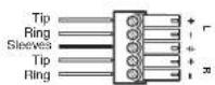
Balanced Stereo Input
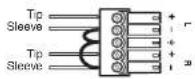
Unbalanced Stereo Input
Wiring the captive screw audio input connectors
⑨ Audio input (RCA) — Connect an unbalanced audio input source to these female RCA connectors. (See the diagram below.)
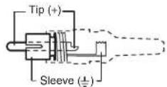
RCA plug diagram
⑩ Audio outputs — Connect speakers to these 5-pole captive screw connectors. Wire the captive screw connectors for stereo output as shown in the following diagram.
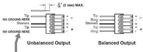
CAUTION
For unbalanced audio, connect both sleeves to the center contact ground. DO NOT connect the sleeves to the negative (-) contacts.
Do not tin the wires!
Wiring the captive screw audio output connectors
⑪ Audio outputs (RCA) — Connect speakers to these RCA connectors. (See the plug diagram under ⑨, above.)
⑫ Video input (composite video) — Connect a composite video source to this female BNC connector.
⑬ Video input (S-video) — Connect an S-video source to this female 4-pin mini DIN connector.
Installation and Rear Panel, cont'd
Setting the Audio Output Gain
On the DA 6SVA EQ, DA 6AV EQ, and DA 6A audio models, you can set the gain for the left and right channels independently.
NOTE This applies only to models with captive screw audio connectors.
On the internal board, each audio output has a set of jumpers (one left and one right). By placing these jumpers on the appropriate pins on the board, you can set the gain for each channel to -6 dB, 0 dB, +6 dB, or unity, depending on whether the output is wired for balanced or unbalanced audio.
To set the gain for an output channel using the internal jumpers,
- Using an Extron Tweeker or other small Phillips screwdriver, remove the six screws from the sides and top of the unit, and carefully lift off the top cover.
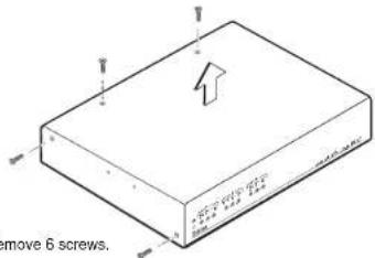
Removing the top cover from the DA
- By default, all jumpers are on the middle and right pins for each output's right and left channel — the configuration for balanced audio. (See the photograph on the next page.)
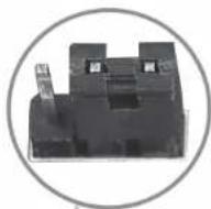
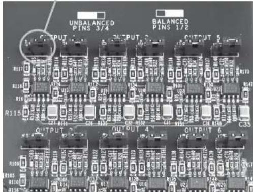
Jumpers on the internal board in their default (balanced) position
To change any output channel to unbalanced audio, lift the jumper off the middle and right pins, and place it on the left and middle pins, as shown in the following illustration.
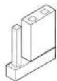
Balanced audio (default)
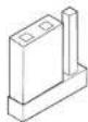
Unbalanced audio
Output gain jumper positions for balanced and unbalanced audio
- Repeat step 2 for each output channel that you want to set.
Installation and Rear Panel, cont'd
The following table shows the resulting gain levels for each possible jumper position and balanced/unbalanced wiring combination.
| Output Wiring\Jumper Position | Balanced(Jumper on right and middle pin) | Unbalanced(Jumper on left and middle pin) |
| Balanced | 0 dB | +6 dB |
| Un balanced | -6 dB | 0 dB |
For example, if you wire output 1 as an unbalanced audio and you place the jumpers for both channels on the left and middle pins, the gain is 0 dB.

DA AV EQ Series
3 Chapter Three
Front Panel Features and Operation
Front Panel Features
Gain and Equalization Controls
Front Panel Features and Operation
Front Panel Features
The following diagrams show the five different front panel configurations of the DA AV EQ series.
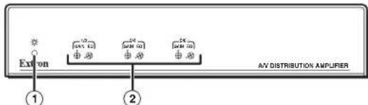
DA 6AV EQ, DA 6AV RCA EQ, and DA 6V EQ front panel
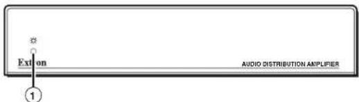
DA 6A and DA 3AV RCA front panel
NOTE
The above illustration shows the DA 6A front panel. The DA 3AV RCA front panel is identical except that it is identified in the lower-right corner as "A/V Distribution Amplifier."
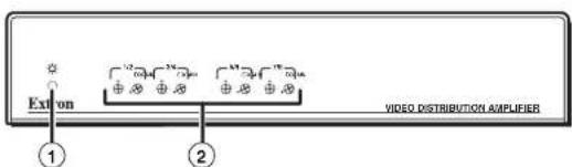
DA 8V/4V Dual EQ front panel
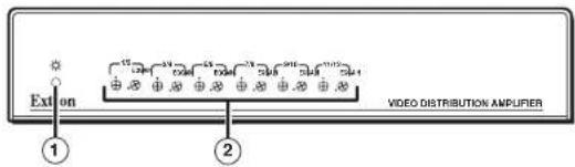
DA 6V/12V Dual EQ front panel
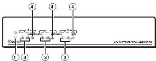
DA 6SV EQ, DA 6SVA EQ, and DA 6SVA RCA EQ front panel
① Power indicator LED — This green LED lights when the distribution amplifier is receiving power.
② Gain and EQ potentiometers — (Composite video models; one set for each pair of outputs) Use an Extron Tweeker or a small Phillips screwdriver to rotate these potentiometers to adjust for gain and equalization (EQ) for connected devices with long cables.
③ Gain and EQ potentiometers (luma) — (SV and SVA EQ models; one set for each pair of outputs) Use an Extron Tweeker or a small Phillips screwdriver to rotate these potentiometers (labeled with Y, above it) to adjust the luminance gain and equalization (EQ) when devices with long cables are connected.
④ Gain potentiometer (chroma) — (SV EQ and SVA EQ models; one for each pair of outputs) Use an Extron Tweeker or a small Phillips screwdriver to rotate this potentiometer (labeled with C, above it) to adjust the chroma gain.
Front Panel Features and Operation, cont'd
Gain and Equalization Controls
To set up your DA AV EQ, you may need to adjust the gain and equalization (EQ) for the output cable lengths. Gain and EQ are adjusted from the front panel of all DA AV EQ series products except the DA 6A and DA 3AV RCA. On S-video models, you can adjust luma (Y) gain and equalization, and chroma (C) gain. On composite video models, you can adjust Gain and EQ. Adjustments are made for each pair of outputs.
Gain and EQ potentiometers (pots) on the front panels enable you to make gain and equalization adjustments. Each pot has a white dot either above it (composite and Y gain) or to the lower left of it (EQ and C gain). These dots indicate 0 dB unity.
Use an Extron Tweeker or a small Phillips screwdriver to rotate these pots clockwise to increase gain or equalization, or counterclockwise to decrease.
The DA AV EQ products have one EQ pot and one or two Gain pots for each pair of outputs. Therefore, gain and equalization can be adjusted only for a pair of outputs at a time. For example, if you adjust the equalization pot for output 1, output 2 is automatically adjusted at the same time and by the same amount.
NOTE This means that you should have cables of the same length for both outputs of a pair.
- DA 6V EQ, DA 6AV EQ, DA 6AV EQ RCA, DA 8V/4V Dual EQ, and DA 12V/6V Dual EQ — The front panels of these models feature one Gain and one EQ pot for each pair of outputs. The illustration below shows the Gain and EQ pots for outputs 1 and 2.
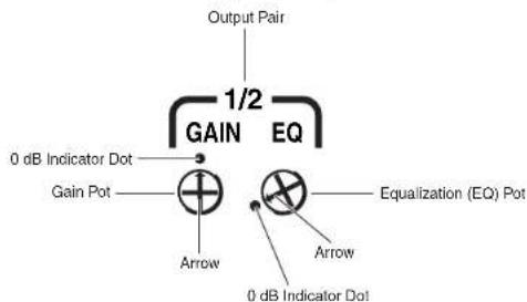
Gain and EQ potentiometers for an output pair
- DA 6SV EQ, DA 6SVA EQ, and DA 6SVA RCA EQ — The front panels of these models each contain one Y Gain, one Y EQ, and one C Gain potentiometer for each pair of outputs. The illustration below shows the Y Gain, EQ, and C Gain potentiometers for outputs 1 and 2.
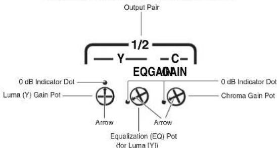
flowchart
graph TD
    A["Output Pair"] --> B["1/2"]
    B --> C["Y"]
    C --> D["EQGAIN"]
    D --> E["Chroma Gain Pot"]
    D --> F["0 dB Indicator Dot"]
    D --> G["Luma (Y) Gain Pot"]
    D --> H["Arrow"]
    D --> I["Arrow"]
    D --> J["Equalization (EQ) Pot (for Luma [Y"])]
Luma and chroma Gain and EQ potentiometers for an output pair
Settings for short cables
At the factory, the DA AV EQ pots are set precisely to the unity gain position (with the arrow on the pot pointing to the dot beside or above it). If you are using very short output cables, do not turn these pots; leave them at the factory default setting. If the pots have already been turned, reset them to the default position. The illustration below shows outputs 1 and 2 set to the unity gain position.
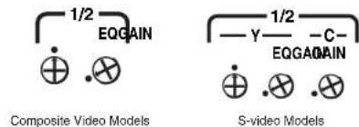
Potentiometers for outputs 1 and 2 at unity gain settings
Front Panel Features and Operation, cont'd
Adjusting for long cables
If you are using long cables, you need to adjust the Gain and EQ potentiometers (pots) until you have the best picture quality. Using an oscilloscope is recommended; however, you can make these adjustments without one. Both methods are described below.
Adjusting with an oscilloscope
- Feed a grayscale signal from an Extron VTG 300/400 or other A/V test generator to the input of the DA AV EQ.
- Remove the far end of the output cable from the display, and connect it to the oscilloscope with 75 ohm termination.
- Adjust the composite video or Y Gain pot to achieve 0.7 Vp-p for the white bar of the test pattern. For the S-video models, adjust the C gain pot to achieve 0.3 Vp-p of color burst level.
- Adjust the EQ pot until no overshooting or round corners appear on the test pattern.
- Repeat steps 1 through 4 for all other output pairs.
- Plug the far end of the cable back into the display device.
Adjusting without an oscilloscope
- Feed a grayscale signal from an Extron VTG 300/400 or other A/V test generator to the input of the DA AV EQ.
- Adjust the composite video or Y Gain pot until the picture from the display device appears to have the correct brightness and contrast.
- Adjust the EQ pot until the picture appears sharp and without visible smearing.
- Repeat steps 1 through 3 for all other output pairs.

DA AV EQ Series
Appendix A
Specifications, Parts, and Accessories
Specifications
Models
Included Parts
Optional Accessories
Cables
Specifications, Parts, and Accessories
Specifications
Video
Gain (all models except DA 6A and DA 3AV RCA)
Video and Y ....-1 dB to +3 dB (x 0.9 to x 1.4), adjustable per every 2 outputs
C (chroma) 0 dB to +10 dB (x 1 to x 3), adjustable for
DA 6SV EQ, DA 6SVA EQ, and
DA 6SVA RCA EQ
Equalization (all models except DA 6A and DA 3AV RCA)
0 dB to +6 dB (x 1 to x 2) at 5 MHz,
adjustable per every 2 outputs
Bandwidth 150 MHz (-3 dB)
Output cable driving distance ... Up to 1000 feet with Mini HR cable
Up to 1500 feet with RG6 or RG59 cables
Video input and loop-through
Number/signal type
DA 6V EQ, DA 6AV EQ, DA 6AV RCA EQ, and DA 3AV RCA
1 composite video input, 1 composite
video passive loop-through
DA 6SV EQ, DA 6SVA EQ, and DA 6SVA RCA EQ
1 S-video, 1 S-video passive loop-through
DA 12V/6V Dual EQ and DA 8V/4V Dual EQ
1 composite video and 1 buffered loop-
through or 2 composite video
Connectors
DA 6V EQ, DA 6AV EQ, DA 6AV RCA EQ, and DA 3AV RCA
1 female BNC (input), 1 female BNC
(loop-through)
DA 6SV EQ, DA 6SVA EQ, and DA 6SVA RCA EQ
1 female 4-pin mini DIN (input) and
1 female 4-pin mini DIN (loop-through)
DA 12V/6V Dual EQ ..... 2 female BNC
DA 8V/4V Dual EQ ..... 2 female BNC
Nominal level 1 Vp-p for composite video and for Y of
5-video
0.3 Vp-p for C of S-video
Minimum/maximum levels
Composite video or Y signal
0.4 V to 2.0 Vp-p with no offset at unity
gain
DA 6SV EQ, DA 6SVA EQ, and DA 6SVA RCA EQ
Y: 0.4 V to 2.0 Vp-p with no offset at unity
gain
Impedance
DA 8V/4V Dual EQ and DA 12V/6V Dual EQ
75 ohms
All other models ...... 75 ohms or Hi-Z, selectable
Return loss -30 dB @ 5 MHz
DC offset (max. allowable) ..... 4.0 V, AC coupled
Video output
Number/signal type
DA 6V EQ, DA 6AV EQ, and DA 6AV RCA EQ
6 composite video
DA 6SV EQ, DA 6SVA EQ, and DA 6SVA RCA EQ
6 S-video
DA 12V/6V Dual EQ ..... 12 composite video
DA 8V/4V Dual EQ ...... 8 composite video
DA 3AV RCA .... 3 composite video
Connectors
DA 6V EQ, DA 6AV EQ, and DA 6AV RCA EQ
6 female BNC
DA 6SV EQ, DA 6SVA EQ, and DA 6SVA RCA EQ
DA 12V/6V Dual EQ ..... 12 female BNC
DA 8V/4V Dual EQ ..... 8 female BNC
DA 3AV RCA .... 3 female BNC
Nominal level 1 Vp-p for composite video and for Y of
S-video
0.3 Vp-p for C of S-video
Minimum/maximum levels ..... 0.4 V to 2.0 Vp-p
Impedance 75 ohms
Return loss ...... -30 dB @ 5 MHz
Sync
Standards NTSC 3.58, NTSC 4.43, PAL, SECAM
Specifications, Parts, and Accessories, cont'd
Audio
Gain.... Unity when internal jumpers are set to match output wiring. See table below for other conditions.
| Output Wiring\Jumper Position | Balanced(Jumper on right and middle pin) | Unbalanced(Jumper on left and middle pin) |
| Balanced | 0 dB | +6 dB |
| Un balanced | -6 dB | 0 dB |
Frequency response..... 20 Hz to 20 kHz, ±0.08 dB (with voltage reference @ 1 kHz)
THD + Noise 0.03% @ 1 kHz at nominal level
S/N (at any output)....>90 dB, unbalanced, at maximum output (unweighted)
Stereo channel separation ..... >80 dB @ 1 kHz; >60 dB @ 20 kHz
CMRR ....>75 dB @ 20 Hz to 20 kHz
Output cable driving distance ... Up to 1000 feet with STP 22 cable
Audio input
Number/signal type
RCA models .... 1 stereo, unbalanced
DA 6A, DA 6AV EQ, and DA 6SVA EQ
1 stereo, balanced/unbalanced
Connectors
RCA models .... 1 pair female RCA
DA 6A, DA 6AV EQ, and DA 6SVA EQ
(1) 3.5 mm captive screw connector, 5 pole
Impedance
RCA models .... 18 k ohms, unbalanced, DC coupled
DA 6A, DA 6AV EQ, and DA 6SVA EQ
18 k ohms unbalanced,
24k ohms balanced, DC coupled
Nominal level ...... Compatible with +4 dBu (1.23 Vrms),
0 dBu (0.775 Vrms), -10 dBV (316 m Vrms),
-20 dBV (100 m Vrms)
Maximum level
RCA models ....+18 dBu, (unbalanced) at 1% THD+N
DA 6A, DA 6AV EQ, and DA 6SVA EQ
+24 dBu, (balanced) at 1%THD+N
NOTE 0 dBu = 0.775 Vrms, 0 dBV = 1 Vrms, 0 dBV ≈ 2 dBu
A-4 DA AV EQ Series • Specifications, Parts, and Accessories
Audio output
Number/signal type
DA 6AV RCA EQ and DA 6SVA RCA EQ
6 stereo, unbalanced
DA 3AV RCA .... 3 stereo, unbalanced
DA 6A, DA 6AV EQ, and DA 6SVA EQ
6 stereo, balanced/unbalanced
Connectors
DA 6AV RCA EQ and DA 6SVA RCA EQ
6 pairs of female RCA jacks
DA 3AV RCA .... 3 pairs of female RCA jacks
DA 6A, DA 6AV EQ, and DA 6SVA EQ
(6) 3.5 mm captive screw connectors,
5 pole
Impedance
RCA models 50 ohms unbalanced
DA 6AV EQ, DA 6SVA EQ, and DA 6A
50 ohms unbalanced, 100 ohms balanced
Maximum level (Hi-Z)
RCA models ....>+18 dBu, unbalanced at 1% THD+N
DA 6A, DA 6AV EQ, and DA 6SVA EQ
+24 dBu, balanced at 1% THD+N
Maximum level (600 ohm)
DA 6A, DA 6AV EQ, and DA 6SVA EQ
+15 dBm, balanced at 1%THD+N
General
Power.... 100 VAC to 240 VAC, 50/60 Hz, 8 watts, internal
Temperature/humidity .... Storage: -40 to +158 °F (-40 to +70 °C) / 10% to 90%, noncondensing Operating: +32 to +122 °F (0 to +50 °C) / 10% to 90%, noncondensing
Rack mount.... Yes, with optional 1U, 9.5" deep rack shelf, part #60-190-01 (RSU 129) or 60-604-01 (RSB 129); or 1U, 6" deep rack shelf, part #60-190-10 (RSU 126) or 60-604-10 (RSB 126) Also furniture mountable with an optional Under-Desk Mounting Kit, #70-077-01, or Through-Desk Mounting Kit, #70-077-02
Enclosure type...... Metal
DA AV EQ Series • Specifications, Parts, and Accessories
Specifications, Parts, and Accessories, cont'd
Enclosure dimensions 1.7" H x 8.7" W x 6.0" D
(1U high, half rack wide)
4.3 cm H × 22.1 cm W × 15.2 cm D
(Depth excludes connectors.)
Cooling ...... Convection, unvented
Product weight 2 lbs (0.9 kg)
Shipping weight 4 lbs (2 kg)
Vibration ...... ISTA 1A in carton (International Safe
Transit Association)
Listings UL, CUL
Compliances ...... CE, FCC Class A, VCCI, AS/NZS, ICES
MTBF 30,000 hours
Warranty 3 years parts and labor
NOTE All nominal levels are at ±10%.
NOTE Specifications are subject to change without notice.
Models
| Model | Part number |
| DA 6V EQ | 60-692-01 |
| DA 6AV EQ | 60-692-21 |
| DA 6AV RCA EQ | 60-692-31 |
| DA 6SV EQ | 60-692-02 |
| DA 6SVA EQ | 60-692-22 |
| DA 6SVA RCA EQ | 60-692-32 |
| DA 6A | 60-692-20 |
| DA 8V/4V Dual EQ | 60-693-01 |
| DA 12V/6V Dual EQ | 60-694-01 |
| DA 3AV RCA | 60-695-31 |
Included Parts
These items are included in each order for a DA AV EQ:
Included part Part number
| IEC power cord |
| 5-pin 3.5 mm captive screw connectors (7) 10-10-319(DA 6AV EQ, DA 6SVA EQ, and DA 6A) |
| Tweeker (small screwdriver) |
| Rubber feet (not attached) |
| DA AV EQ Series User's Manual |
Optional Accessories
These items can be ordered separately:
Accessory Part number
| RSU 129 1U, 9.5" Deep Universal Rack 60-190-01 Shelf Kit |
| RSB 129 1U, 9.5" Deep Basic Rack Shelf 60-604-01 |
| RSU 126 1U, 6" Deep Universal Rack Shelf 60-190-10 Kit |
| RSB 126 1U, 6" Deep Basic Rack Shelf 60-604-10 |
| MBU 125 Under-desk Mount Kit 70-077-01 |
| MBU 129 Through-desk Mount Kit 70-077-02 |
Specifications, Parts, and Accessories, cont'd
Cables
The following cables can be ordered as needed:
| Cable Part number |
| MHR-2 SVM-M Male to Male 4-pin 26-316-xxMini DIN S-Video Cables (S-video models only) |
| MHR-2P SVM-M Male to Male 4-pin 26-522-xxMini DIN S-Video cables, plenum (S-video models only) |
| RG6 BNC Series BNC Male to Male Single 26-383-xxConductor SHR cables |
| CSR 6 Captive Screw to RCA Female 26-575-01Audio Adapter (audio models only) |
| RCA Male to Male Stereo Audio cable IN87xx (audio models only) |
- Extron. Electronics INTERFACING, SWITCHING AND DISTRIBUTION
- Audio/Video Distribution Amplifiers
- Precautions
- Safety Instructions • English
- Caution
- Avertissement
- USA, Canada, South America, Europe, Africa, and the Middle East and Central America:
- Asia: Japan:
- 安全须知 · 中文
- NOTE
- Quick Start Guide — DA AV EQ Series
- Step 1
- Step 2
- Step 3
- Wiring the captive screw audio output connectors
- Quick Start Guide — DA AV EQ Series, cont'd
- Step 4
- Step 5
- Potentiometers at unity gain setting
- Table of Contents
- Chapter One
- Introduction
- About this Manual
- About the DA AV EQ Series
- Models
- Features
- Introduction, cont'd
- Application diagrams
- DA AV EQ Series
- Chapter Two
- Installation and Rear Panel
- Mounting the DA AV EQ Series
- Tabletop use
- Rack mounting
- UL rack mounting requirements
- Rack mounting procedure
- Installation and Rear Panel, cont'd
- Furniture mounting
- Through-desk mounting
- Through-desk mounting the DA AV EQ
- Rear Panel Features and Cabling
- Setting the Audio Output Gain
- Removing the top cover from the DA
- Chapter Three
- Front Panel Features and Operation
- Front Panel Features
- DA 6A and DA 3AV RCA front panel
- Front Panel Features and Operation, cont'd
- Gain and Equalization Controls
- Settings for short cables
- Adjusting for long cables
- Adjusting with an oscilloscope
- Adjusting without an oscilloscope
- Appendix A
- Specifications, Parts, and Accessories
- Specifications
- Video
- Video input and loop-through
- Video output
- Sync
- Specifications, Parts, and Accessories, cont'd
- Audio
- Audio input
- A-4 DA AV EQ Series • Specifications, Parts, and Accessories
- Audio output
- General
- Included Parts
- Optional Accessories
- Cables
Brand : Extron
Model : DA 6A
Category : Audio/video switch