
MLC 62 RS MK - Wall remote Extron - Free user manual and instructions
Find the device manual for free MLC 62 RS MK Extron in PDF.


| Product Type | Media Link Controller |
| Brand | Extron |
| Model | MLC 62 RS MK |
| Dimensions (H x W x D) | 1.7 x 4.0 x 3.0 in (4.3 x 10.2 x 7.6 cm) |
| Weight | 1.0 lb (0.45 kg) |
| Power Supply | 12 VDC, 1 A external power supply (included) |
| Power Consumption | 6 watts (typical) |
| RS-232 Control Ports | 2 (bidirectional, up to 115k baud) |
| Relay Control Ports | 2 (normally open, 24 VAC/DC, 1 A) |
| IR Control Ports | 2 (learning IR, output via IR emitter) |
| Digital I/O Ports | 4 (configurable as input or output, 5 V logic) |
| Compatible AV Switching | Extron SW Series, MVX Series, and others |
| Mounting | Furniture-mountable with included brackets |
| Operating Temperature | 32 to 122 °F (0 to 50 °C) |
| Storage Temperature | -4 to 158 °F (-20 to 70 °C) |
| Relative Humidity | 10% to 90% (noncondensing) |
| Clean the device | Use a dry, soft cloth; avoid liquids and solvents |
| Safety | Use only supplied power supply; do not expose to moisture |
| Spare Parts Availability | Contact Extron for replacement power adapters and IR emitters |
| Repairability | No user-serviceable parts; refer to qualified service personnel |
Frequently Asked Questions - MLC 62 RS MK Extron
User questions about MLC 62 RS MK Extron
0 question about this device. Answer the ones you know or ask your own.
Ask a new question about this device
Download the instructions for your Wall remote in PDF format for free! Find your manual MLC 62 RS MK - Extron and take your electronic device back in hand. On this page are published all the documents necessary for the use of your device. MLC 62 RS MK by Extron.
USER MANUAL MLC 62 RS MK Extron
MLC 60 Series • Setup Guide for the MLC 62 RS EU and the MLC 62 RS MK
IMPORTANT NOTE:
Go to www.extron.com for the complete MLC 60 Series user guide, installation instructions, and specifications before connecting the product to the power source.

The Extron MLC 62 RS EU and the MLC 62 RS MK are keypad controllers for use in classrooms and meeting facilities. The EU model attaches to a single size European electrical junction box with a 60 mm mounting center. The MK model mounts to a single size MK junction box. The controllers have backlit soft touch buttons and can control common AV functions, including power, input switching, and volume. Both models have RS-232 serial and IR ports for universal display control. A digital input and two relays enable monitoring and controlling of other devices in the room. Both models have six-button and eight-button options.
NOTES:
• Installation and service must be performed by authorized personnel only.
• For full installation, configuration, and operation details, see the MLC 60 Series User Guide, available at www.extron.com.

MLC 62 RS EU Front Panel
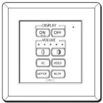
MLC 62 RS MK Front Panel

Rear Panel

natural_image
Technical line drawing of a left side panel assembly (no text or symbols)Figure 1. Front and Rear Panels of the MLC 62 RS EU and MLC 62 RS MK
Installation Steps
1. Prepare the installation site.
a. If using an electrical box, install it, following the directions provided with it. The MLC 62 EU and MK controllers can be installed in standard EU and MK one-gang electrical wall boxes.
ATTENTION:
b. Prepare and pull the cables through the electrical box.
2. Optional: change the faceplate:
a. Remove the faceplate from the MLC module as follows:
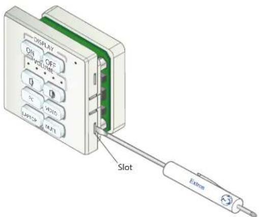
i. On the right and left edges of the faceplate are two pairs of slots, into which two small tabs on either side of the MLC fit. Insert the flat end of a small screwdriver into each side slot (as shown at right) and press inward until the tab is released from its slot.
ii. Lift the faceplate off the MLC circuit board.
MLC 62 EU and MLC 62 MK • Setup Guide (Continued)
b. If desired, replace the buttons in the faceplate as follows:
i. From the front of the faceplate, press the button membrane to be replaced backward through its faceplate openings until it comes free. If replacing the faceplate, repeat this step until all the buttons are removed.
ii. On the back of the faceplate, place the new button membrane at the desired location, with the two pegs in the upper-left and lower-right corners of the membrane in the faceplate holes at opposite corners of the row (see the images at right). Press the pegs and buttons of the membrane into the faceplate.
iii. Repeat step 2b as needed.

c. Reattach or replace the faceplate as follows (see the image at right):
i. Making sure that both the MLC and the faceplate are upright, hold the MLC with its circuit board against the back of the faceplate, aligning the two tabs on each side of the MLC with the two slots on each side of the faceplate.
ii. Each tab has a ridge that must snap into a slot on the side of the MLC. Press the MLC into the faceplate until the ridges on all four tabs snap into place.

- Connect the cables to the MLC rear panel ports. Attach the cables and IR emitters to the rear panel of the MLC and to the display device or switcher as required.
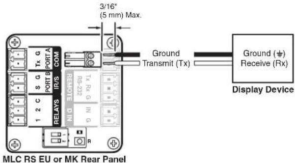
- Port A Com: Connect a display device or switcher to this serial port to control the device via RS-232 (see the image at right).
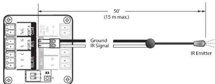
- Port B IR/S: Connect a display device, switcher, or up to two IR emitters to this port (see the image at right). You can configure this port for either serial or IR communication using the MLC 55, 62 and 64 Series Configuration Program.
MLC RS EU or MK Rear Panel
- Relay ports: The relay ports provide connections for two relays. Connect one or two devices (such as a low-voltage controller and a motorized screen, shown in the example at right) to this port. The relay ports are normally open and rated for 24 VDC, 1 A.
NOTE: If you use both relay ports, connect the ground wires of both devices to common pin 3.

- Digital Input port (D IN) — Connect a switch or sensor to this port to control other devices in the room that are connected to the MLC serial, IR, or relay ports. The port monitors the high and low states of the connection between the switch or sensor and the connected device. For the voltage thresholds, a voltage below 1.0 VDC is considered logic low, and a voltage above 1.5 VDC is considered logic high. When a threshold between the states is crossed (from high to low and vice versa), the selected action occurs.
By default, this port is configured with a +5 VDC pull-up resistor for use with basic non-powered switches. If the device being connected has its own power source, configure the port to disable the pull-up mode (see the configuration program help file for port setup procedures). To wire this port, see the example above.

4. Connect and apply power.
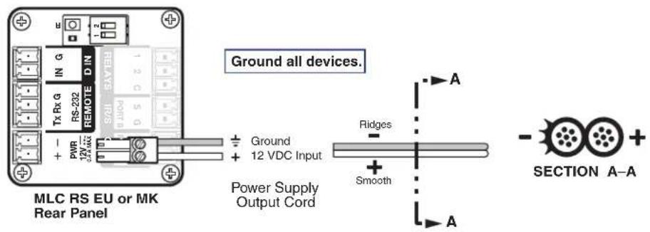
Connect the included power supply to the MLC Pwr connector as shown at right, then connect power to all devices in the system.
5. Connect the MLC to the computer.
Use either of the following methods:
- Connect a USB A-to-USB mini B cable between the USB configuration port on the MLC side panel and a USB port on your computer as shown at right, or

MLC 62 EU and MLC 62 MK • Setup Guide (Continued)
- Wire an RS-232 cable to the provided 3-pole connector and connect it between the MLC Remote port and the computer serial port, as shown at right.
- Configure the MLC buttons and ports (see the MLC 55, 62 and 64 Series Configuration Program Help File).
a. Load and install the configuration software to your computer from the Extron website.
b. Obtain device drivers. Drivers for the devices to be connected to the MLC rear panel IR and serial ports can be downloaded from www.extron.com. They can also be obtained using the configuratic
c. Upload the configuration to the MLC.

-
Test the system to ensure that the MLC is functioning properly.
-
Decide where the MLC will be located. Take into consideration the position of wall studs and windows that could obstruct cable runs.
-
Mount the MLC.
Before mounting the MLC to a wall or furniture, make sure that all device cables are connected to the MLC rear panel.
NOTES:
- Recommended: To keep the MLC securely in place and prevent it from being easily pulled from its mounting, ensure that the side of the bracket with Front engraved on it faces out (away from the electrical box).
- To be able to remove the MLC easily from its mounting, attach the bracket with Front facing inward (toward the electrical box).
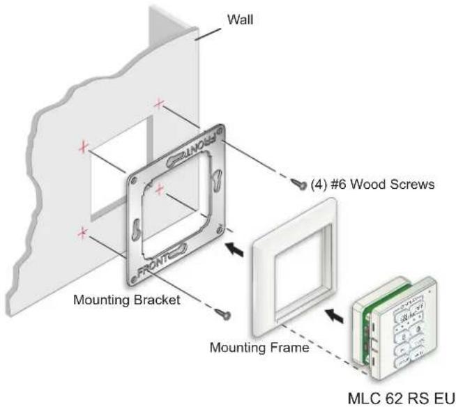
a. Use the provided four mounting hardware screws or other hardware screws appropriate for the mounting surface to attach each corner of the metal mounting bracket to the wall or furniture, or
If using an electrical box:
i. Place the provided metal mounting bracket onto the box, aligning the keyhole slots in the bracket with the screw holes on the right and left sides of the box.
ii. Secure the bracket to the mounting surface, using two of the included screws in the keyhole slots at top and bottom (see the image at right).
NOTES:
- The metal brackets provided with the EU and MK models are different and are not interchangeable.
- Ensure the bracket is in the correct orientation (with the side marked "Front" facing away from the wall).
- The EU model is attached with screws at the top and bottom.
- The MK model is attached with screws on both the sides.

b. Insert the MLC into the mounting frame and press the entire assembly into the metal mounting bracket. The MLC is secured to the metal bracket by two catches (one on each side) and holds the wallplate in place.
c. Align the MLC wall frame to the mounting bracket, which was attached to the mounting surface in step 9a.
d. Holding the mounting frame in place on the bracket, press the MLC into the frame until the two tabs on either side of the unit snap into the opening of the mounting bracket, holding the MLC in place.
Mounting the MLC 62 RS EU in a Raceway Using a Spacer (Optional)
The MLC 62 RS EU can be mounted in a cable raceway. If there is difficulty with the MLC staying in place when installed in a cable raceway, this may be due to a gap between the mounting bracket and the wall frame. When this gap exists, the tabs on the sides of the MLC do not reach the mounting bracket and the MLC does not snap completely into the bracket. Extron provides a metal spacer that can be installed between the mounting bracket and the rim of the junction box. The spacer has a slightly larger center opening than the mounting bracket.
The spacer looks very similar to the metal mounting bracket, but has a slightly larger center opening and is engraved with the words "Optional Spacer" and "Place behind bracket." Do not use the spacer instead of the metal mounting bracket. The spacer has a larger opening and does not hold the MLC securely in the wallplate.

To install the MLC in a raceway with a spacer:
-
Mount an electrical box in the raceway, following the instructions provided by the manufacturer (see figure 2, ①).
-
If required, align the screw holes of the provided spacer with the holes in the electrical box.
-
Align the screw holes in the metal mounting bracket with the holes in the spacer and electrical box (③).
NOTE: Ensure the front surface of the mounting bracket is facing out (away from the wall).
- Insert two of the included screws into the electrical box ( ②). Leave the screw heads protruding approximately 1/8 inch (3.18 mm) from the surface of the box.
- With the "Front" label facing forward, place the metal mounting bracket onto the spacer so that the screw heads pass through the two keyhole slots in opposite sides of the bracket and spacer.
- Rotate the mounting bracket and spacer as necessary to ensure the MLC will be positioned straight on the mounting surface and not skewed to either side.
- Tighten the screws to secure the bracket and spacer to the electrical box.
- Pull the cables through the electrical box and the wall frame.
- Disconnect power from all devices at the source and connect all cables to the MLC. Run cables through the raceway, electrical box, spacer, metal mounting bracket and wallplate. Connect them to the rear panel (see Step 3: Connect the cables on page 2).
- Insert the MLC into the wallplate (see ⑤) and press the entire assembly into the metal bracket (⑥) until the unit snaps into place. The MLC is secured to the metal bracket by two catches (one on each side) that hold the wallplate in place.

Figure 2. Mounting an MLC 62 RS EU in a Raceway
For information on safety guidelines, regulatory compliances, EMI/EMF compatibility, accessibility, and related topics, see the Extron Safety and Regulatory Compliance Guide on the Extron website.
© 2017-2026 Extron — All rights reserved. www.extron.com
All trademarks mentioned are the property of their respective owners.
Worldwide Headquarters: Extron USA West, 1025 E. Ball Road, Anaheim, CA 92805, 800.633.9876
68-2166-51 Rev. D 02 26


- MLC 60 Series • Setup Guide for the MLC 62 RS EU and the MLC 62 RS MK
- IMPORTANT NOTE:
- NOTES:
- Installation Steps
- Prepare the installation site.
- ATTENTION:
- Optional: change the faceplate:
- MLC 62 EU and MLC 62 MK • Setup Guide (Continued)
- Connect and apply power.
- Connect the MLC to the computer.
- Mounting the MLC 62 RS EU in a Raceway Using a Spacer (Optional)
Brand : Extron
Model : MLC 62 RS MK
Category : Wall remote