MasterBay - Router SPL - Free user manual and instructions
Find the device manual for free MasterBay SPL in PDF.


| Product Type | Router |
| Brand | SPL |
| Model | MasterBay |
| Dimensions (W x D x H) | 200 x 150 x 30 mm |
| Weight | 0.3 kg |
| Power Supply | DC 12V, 1A |
| Wired Ports | 4 x Gigabit Ethernet (LAN), 1 x Gigabit Ethernet (WAN) |
| Wireless Standards | 802.11b/g/n/ac, Dual-Band (2.4 GHz + 5 GHz) |
| Maximum Wireless Speed | Up to 1200 Mbps (300 Mbps on 2.4 GHz + 867 Mbps on 5 GHz) |
| Antennas | 4 external antennas, fixed |
| Security Protocols | WPA2-PSK, WPA/WPA2, WEP |
| Management Interface | Web-based GUI (HTTP/HTTPS) |
| Advanced Features | Guest network, parental controls, QoS, VPN pass-through |
| Operating Temperature | 0°C to 40°C |
| Humidity | 10% to 90% non-condensing |
| Certifications | CE, FCC |
| Installation | Easy setup via web assistant or mobile app |
| Cleaning | Wipe with dry cloth; avoid liquids |
| Maintenance | Keep ventilated; reboot periodically |
| Spare Parts | Power adapter (model SPL-PA12V1A) |
| Reparability | Repairable by qualified technician; no user-serviceable parts inside |
| Package Contents | Router, power adapter, Ethernet cable, quick start guide |
Frequently Asked Questions - MasterBay SPL
User questions about MasterBay SPL
0 question about this device. Answer the ones you know or ask your own.
Ask a new question about this device
Download the instructions for your Router in PDF format for free! Find your manual MasterBay - SPL and take your electronic device back in hand. On this page are published all the documents necessary for the use of your device. MasterBay by SPL.
USER MANUAL MasterBay SPL
The information in this document has been carefully verified and is assumed to be correct. However Sound Performance Lab (SPL) reserves the right to modify the product described in this manual at any time. Changes without notice. This document is the property of SPL and may not be copied or reproduced in any manner, in part or full without the authorization of SPL.
Limitations of Liability:
In no event will SPL be liable for any damages, including loss of data, lost profits, cost of cover or other special, incidental, consequential or indirect damages arising from the use of the unit, however caused and on any theory of liability. This limitation will apply even if SPL or an authorized dealer has been advised of the possibility of such damage.
Sound Performance Lab
SPL electronics GmbH
P.O. Box 12 27, D-41368 Niederkruechten, Germany
Phone +49 2163 983 40, Fax +49 2163 983 420
Email: info@spl.info, Internet: spl.info

© 2006 SPL electronics GmbH
All rights reserved. Technical specifications and appearance are subject to change without notice.

Contents
MasterBay Remote Control, Model 2487 4
MasterBay Dual-Channel Insert Box, Model 2488 5
MasterBay Eight-Channel Insert Box, Model 2268 6
Wiring Diagram 7
Control Surface, Operation 8
Operation 9
EDAC 38 pin connectors/pin configuration 10
DB 25 pin connectors/pin configuration 11
Measurements 11
Warranty 12
Fade In
Automated routing of processors in a mastering chain is becoming more and more of an issue for mastering engineers. The SPL MasterBay system allows for instant comparison of single processors or processor chains which can be determined and stored in three different sequences.
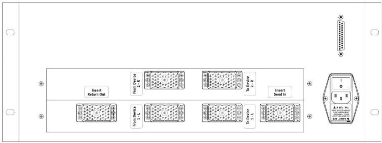
The MasterBay is available as dual- or eight-channel system. Each of the fully balanced, entirely passive insert boxes is controlled by the MasterBay Remote Control which can be placed upon the desktop or built into a desk.
Dual-channel MasterBay:
Remote Control model 2487 and insert box model 2488
Eight-channel MasterBay:
Remote Control model 2487 and insert box model 2268

The MasterBay Remote Control is connected to one of the MasterBay Insert boxes via the rear DB 25 connector (10 m cable included). The remote houses a CPU to control 146 (dual-channel MasterBay) or 584 (eight-channel MasterBay) gold plated relay switches. It is powered from the respective insert box through the DB 25 wiring, so no additional power supply is needed.
See page 9 for operation and page 11 for the pin configuration of the DB 25 connector.
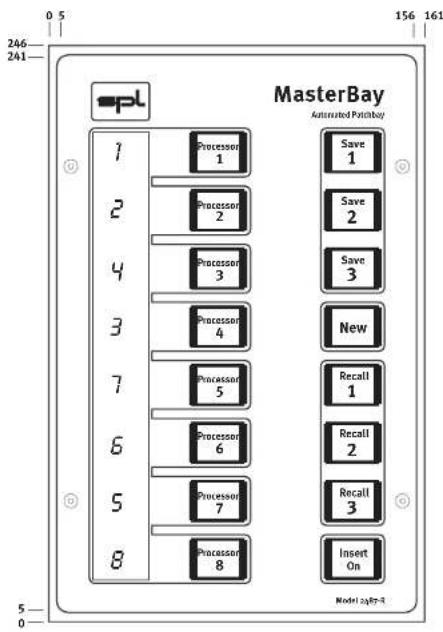
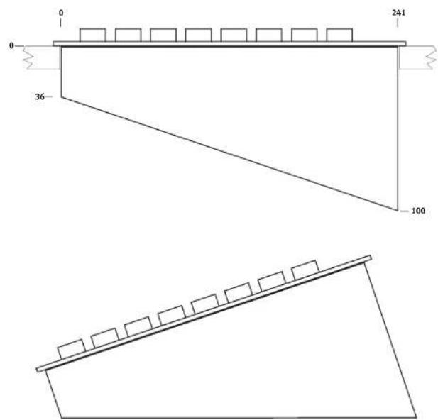
Measurements in millimeter

The MasterBay system is based on a completely passive design with fully balanced signal paths from input to output. All 146 relays are placed on large, double-sided PCBs for switching operation with maximum neutrality in sound quality. A ground path between all audio signal paths ensures the highest possible shielding.
Lavishly dimensioned, linear power supplies based on toroidal transformers are capable of providing adequate current regardless of any demands.
Dimensions
The dual-channel MasterBay insert box comes with detachable 19 inch brackets.
Height: 177 mm/7.08 inch
Width: 440 mm/17,6 inch w/o brackets, 482 mm/19,28 inch with brackets
Depth: 500 mm/20 inch

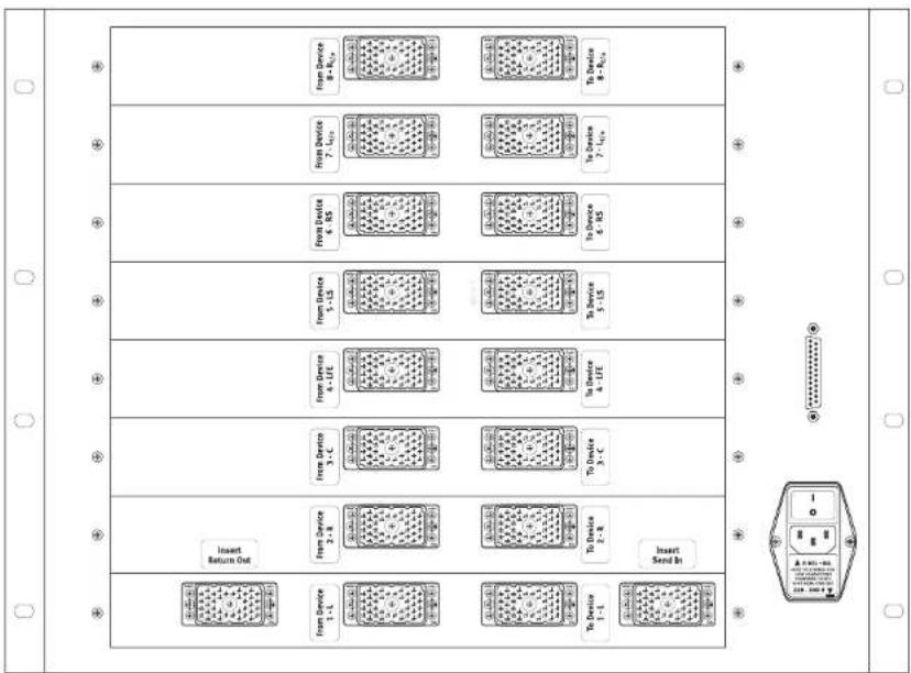
Eight-Channel MasterBay Insert Box, Model 2268
The MasterBay system is based on a completely passive design with fully balanced signal paths from input to output. All 584 relays are placed on large, double-sided PCBs for switching operation with maximum neutrality in sound quality. A ground path between all audio signal paths ensures the highest possible shielding.
Lavishly dimensioned, linear power supplies based on toroidal transformers are capable of providing adequate current regardless of any demands.
Dimensions
The dual-channel MasterBay insert box comes with detachable 19 inch brackets.
Height: 355 mm/14.2 inch
Width: 440 mm/17,6 inch w/o brackets, 482 mm/19,28 inch with brackets
Depth: 500 mm/20 inch
flowchart
graph TD
    A["From Device 1-1"] --> B["To Device 1-1"]
    C["From Device 2-8"] --> D["To Device 2-8"]
    E["From Device 3-C"] --> F["To Device 3-C"]
    G["From Device 4-LFE"] --> H["To Device 4-LFE"]
    I["From Device 5-LS"] --> J["To Device 5-LS"]
    K["From Device 6-RS"] --> L["To Device 6-RS"]
    M["From Device 7-LSV"] --> N["To Device 7-LSV"]
    O["From Device 8-Vin"] --> P["To Device 8-Vin"]
    Q["Insert Return Out"] --> R["To Device 1-1"]
    S["Insert Send In"] --> T["To Device 2-8"]
    U["To Device 3-C"] --> V["To Device 3-C"]
    W["To Device 4-LFE"] --> X["To Device 4-LFE"]
    Y["To Device 5-LS"] --> Z["To Device 5-LS"]
    AA["To Device 6-RS"] --> AB["To Device 6-RS"]

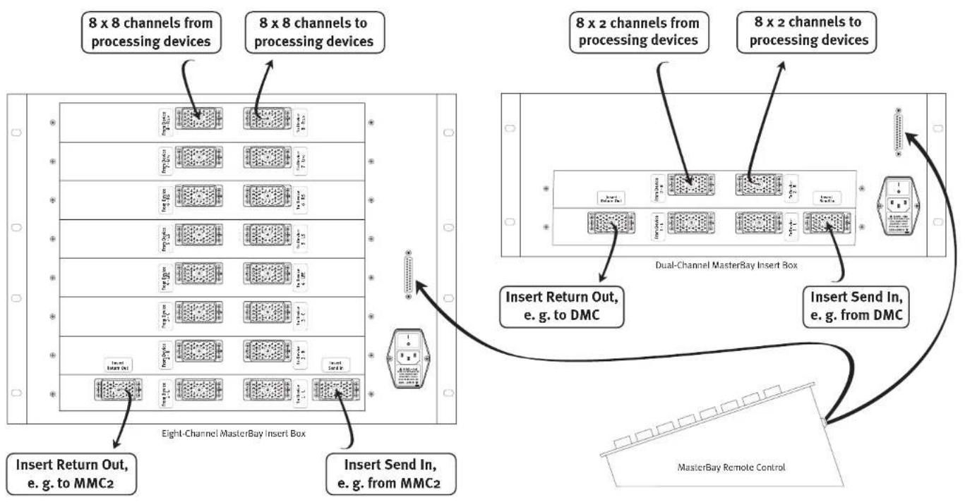
flowchart
graph TD
    A["8 x 8 channels from processing devices"] --> B["Eight-Channel MasterBay Insert Box"]
    C["8 x 8 channels to processing devices"] --> B
    D["8 x 2 channels from processing devices"] --> E["Dual-Channel MasterBay Insert Box"]
    F["8 x 2 channels to processing devices"] --> E
    G["Insert Return Out, e.g. to MMC2"] --> B
    H["Insert Send In, e.g. from MMC2"] --> B
    I["Insert Return Out, e.g. to DMC"] --> E
    J["Insert Send In, e.g. from DMC"] --> E
    K["MasterBay Remote Control"] --> E

To help alleviate the complexity of high-end audio patching, the MasterBay system features dual or eight channel insert boxes to which up to eight processors can be connected. The unique advantage of the MasterBay is that the engineer can specify up to three routings, called "sequences", which can be stored and re-called.
The MasterBay 8, model 2268 supports the connection of eight processors with up to eight channels (64 channels).
The MasterBay 2, model 2488 supports the connection of eight dual-channel processors (16 channels).
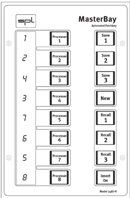
The MasterBay remote provides a button for each of the eight external processors. Labels can be changed to the user's requirements. The covers of the buttons can be lifted to insert a new label.
The order in which the processor selection buttons are activated determines the processor sequence. A seven segment LED-display next to each button indicates the current position of a processor. The mastering engineer can use this feature to compare between sequences in varying order or to compare the same type of processors—such as in the case of an equalizer from Manufacturer A and one of Manufacturer B.
Three memory banks are available which allow an active signal flow sequence to be compared instantly at a button push with three others (for a total of four). An Insert On switch engages the Insert Box or switches to hard-bypass.
Saving a processor sequence
- Press Insert On to activate the signal flow through the insert box.
- When determining a new sequence it is demanding to press the New button first to clear the sequence memory. The LED display shows a “-” besides each processor button.
- Press the Processor buttons in the desired order. At this stage you can only add another processor to the sequence, but you cannot take a processor out of the sequence. This can only be done with recalled sequences, see #7. If the sequence should be changed at this stage, press New to start a new sequence.

- After the first sequence is determined, press Save 1 to store the sequence.
- To create more sequence, press New again and determine a sequence. Press Save 2 or Save 3 to store the new sequence.
- After a sequence is saved, the Save buttons will illuminate to indicate a valid save.
- To recall a saved processor sequence, press the respective Recall button (illumination on).
- The Insert On switch can be used to bypass all processors.
Working with a recalled sequence
To exclude one or more processors from a stored preset, press the according Processor Selection button (illumination off). The processor now is hard-bypassed by relays. It can be switched into the signal path at the former position by pressing the Processor Selection button again (illumination on).
It is not possible to add further processors to recalled sequences. Determine and save a new sequence instead.
When you change a recalled sequence without saving it, this change will apply to another recalled sequence as well. To avoid this, save the changed sequence or press New before recalling the next sequence.
Erasing sequences
In order to clear the memory of Save 1-3, press New and press the respective Save button. Now the illumination of the respective Save button is off.

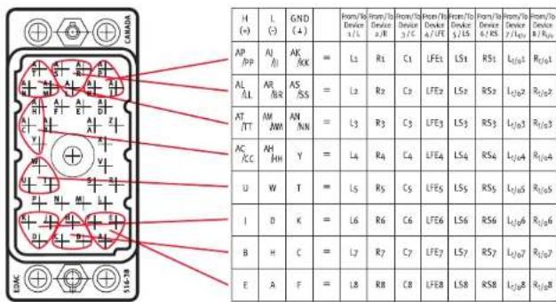
EDAC 38 pin connectors/pin configuration
Dual- and eight-channel MasterBay
"Inser Send" and "Insert Return" connectors
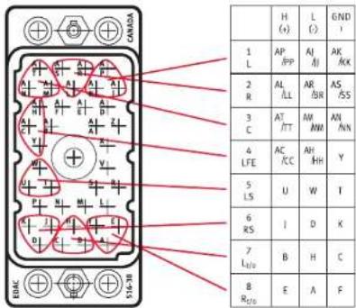
Dual-channel MasterBay
"From Device" and "To Device" connectors
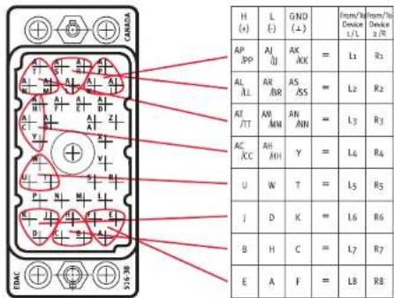
Eight-channel MasterBay, "From Device" and "To Device" connectors

MasterBay Remote Control and MasterBay insert boxes are connected via DB 25 connectors. A 10 m/33 feet cable is included, connecting in a 1:1 pin configuration.
Pin configuration DB 25 connector
Pin 22 -17 V
Pin 11 oV
Pin 25 +10 Va
Pin 2 RS 232-TxD
Pin 3 RS 232-RxD
Pin 7 RS 232-0 V
Pin 1 Ground

Power supply Remote Control

Data exchange
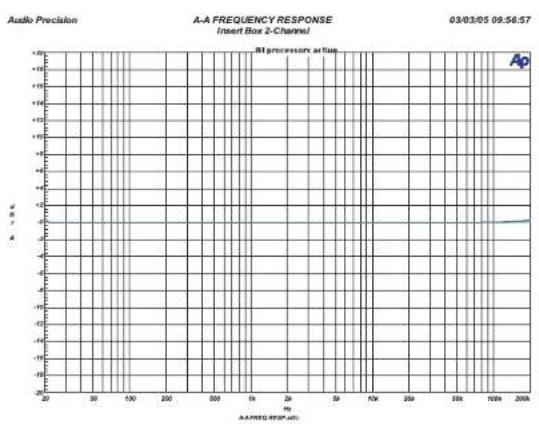
Measurements
line
| Frequency (Hz) | Value | | -------------- | ----- | | 20 | 0 | | 30 | 0 | | 40 | 0 | | 50 | 0 | | 60 | 0 | | 70 | 0 | | 80 | 0 | | 90 | 0 | | 100 | 0 | | 110 | 0 | | 120 | 0 | | 130 | 0 | | 140 | 0 | | 150 | 0 | | 160 | 0 | | 170 | 0 | | 180 | 0 | | 190 | 0 | | 200 | 0 | | 210 | 0 | | 220 | 0 | | 230 | 0 | | 240 | 0 | | 250 | 0 | | 260 | 0 | | 270 | 0 | | 280 | 0 | | 290 | 0 | | 300 | 0 | | 310 | 0 | | 320 | 0 | | 330 | 0 | | 340 | 0 | | 350 | 0 | | 360 | 0 | | 370 | 0 | | 380 | 0 | | 390 | 0 | | 400 | 0 | | 410 | 0 | | 420 | 0 | | 430 | 0 | | 440 | 0 | | 450 | 0 | | 460 | 0 | | 470 | 0 | | 480 | 0 | | 490 | 0 | | 500 | 0 | | 510 | 0 | | 520 | 0 | | 530 | 0 | | 540 | 0 | | 550 | 0 | | 560 | 0 | | 570 | 0 | | 580 | 0 | | 590 | 0 | | 600 | 0 | | 610 | 0 | | 620 | 0 | | 630 | 0 | | 640 | 0 | | 650 | 0 | | 660 | 0 | | 670 | 0 | | 680 | 0 | | 690 | 0 | | 700 | 0 | | 710 | 0 | | 720 | 0 | | 730 | 0 | | 740 | 0 | | 750 | 0 | | 760 | 0 | | 770 | 0 | | 780 | 0 | | 790 | 0 | | 800 | 0 | | Note: The actual values for 'A' are not provided in the code. The 'AP' label is present in the plot area.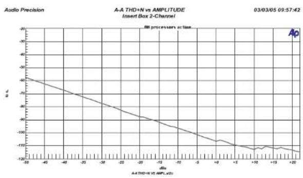
line
| Time (s) | Amplitude (dB) | | -------- | -------------- | | -45 | -60 | | -40 | -70 | | -35 | -80 | | -30 | -90 | | -25 | -100 | | -20 | -110 | | -15 | -115 | | -10 | -118 | | -5 | -120 | | 0 | -122 | | 5 | -123 | | 10 | -124 | | 15 | -125 | | 20 | -126 | | 25 | -127 | | 30 | -128 | | 35 | -129 | | 40 | -130 | | 45 | -131 | | 50 | -132 | | 55 | -133 | | 60 | -134 | | 65 | -135 | | 70 | -136 | | 75 | -137 | | 80 | -138 | | 85 | -139 | | 90 | -140 | | 95 | -141 | | 100 | -142 | | 105 | -143 | | 110 | -144 | | 115 | -145 | | 120 | -146 | | 125 | -147 | | 130 | -148 | | 135 | -149 | | 140 | -150 | | 145 | -151 | | 150 | -152 | | 155 | -153 | | 160 | -154 | | 165 | -155 | | 170 | -156 | | 175 | -157 | | 180 | -158 | | 185 | -159 | | 190 | -160 | | 195 | -161 | | 200 | -162 | | 205 | -163 | | 210 | -164 | | 215 | -165 | | 220 | -166 | | 225 | -167 | | 230 | -168 | | 235 | -169 | | 240 | -170 | | 245 | -171 | | 250 | -172 | | 255 | -173 | | 260 | -174 | | 265 | -175 | | 270 | -176 | | 275 | -177 | | 280 | -178 | | 285 | -179 | | 290 | -180 | | 295 | -181 | | 300 | -182 | | 305 | -183 | | 310 | -184 | | 315 | -185 | | 320 | -186 | | 325 | -187 | | 330 | -188 | | 335 | -189 | | 340 | -190 | | 345 | -191 | | 350 | -192 | | 355 | -193 | | 360 | -194 | | 365 | -195 | | 370 | -196 | | 375 | -197 | | 380 | -198 | | 385 | -199 | | 390 | -200 | | 395 | -201 | | 400 | -202 | | 405 | -203 | | 410 | -204 | | 415 | -205 | | 420 | -206 | | 425 | -207 | | 430 | -208 | | 435 | -209 | | 440 | -210 | | 445 | -211 | | 450 | -212 | | 455 | -213 | | 460 | -214 | | 465 | -215 | | 470 | -216 | | 475 | -217 | | 480 | -218 | | 485 | -219 | | 490 | -220 | | 495 | -221 | | 500 | -222 | | 505 | -223 | | 510 | -224 | | 515 | -225 | | 520 | -226 | | 525 | -227 | | 530 | -228 | | 535 | -229 | | 540 | -230 | | 545 | -231 | | 550 | -232 | | 555 | -233 | | 560 | -234 | | 565 | -235 | | 570 | -236 | | 575 | -237 | | 580 | -238 | | 585 | -239 | | 590 | -240 | | 595 | -241 | | 600 | -242 | | 605 | -243 | | 610 | -244 | | 615 | -245 | | 620 | -246 | | 625 | -247 | | 630 | -248 | | 635 | -249 | | 640 | -250 | | 645 | -251 | | 650 | -252 | | 655 | -253 | | 660 | -254 | | 665 | -255 | | 670 | -256 | | 675 | -257 | | 680 | -258 | | 685 | -259 | | 690 | -260 | | 695 | -261 | | 700 | -262 | | 705 | -263 | | 710 | -264 | | 715 | -265 | | 720 | -266 | | 725 | -267 | | 730 | -268 | | 735 | -269 | | 740 | -270 | | 745 | -271 | | 750 | -272 | | 755 | -273 | | 760 | -274 | | 765 | -275 | | 770 | -276 | | 775 | -277 | | 780 | -278 | | 785 | -279 | | 790 | -280 | | 795 | -281 | | 800 | -282 | | 805 | -283 | | 810 | -284 | | 815 | -285 | | 820 | -286 | | 825 | -287 | | 830 | -288 | | 835 | -289 | | 840 | -290 | | 845 | -291 | | 850 | -292 | | 855 | -293 | | 860 | -294 | | 865 | -295 | | 870 | -296 | | 875 | -297 | | 880 | -298 | | 885 | -299 | | 890 | -300 | | 895 | -301 | | 900 | -302 | | 905 | -303 | | 910 | -304 | | 915 | -305 | | 920 | -306 | | 925 | -307 | | 930 | -308 | | 935 | -309 | | 940 | -310 | | 945 | -311 | | 950 | -312 | | 955 | -313 | | 960 | -314 | | 965 | -315 | | 970 | -316 | | 975 | -317 | | 980 | -318 | | 985 | -319 | | 990 | -320 | | 995 | -321 | | 1000 | -322 | The data is extracted from the image file 'Audio Precision' using the plot. The x-values are the time points (in seconds) and the y-values are the amplitude of the amplitude of the amplitude of the amplitude of the amplitude of the amplitude of the amplitude of the amplitude of the amplitude of the amplitude of the amplitude of the amplitude of the amplitude of the amplitude of the amplitude of the amplitude of the amplitude of the amplitude of the amplitude of the amplitude of the amplitude of the amplitude of the amplitude of the amplitude of the amplitude of the amplitude of the amplitude of the amplitude of the amplitude of the amplitude of the amplitude of the amplitude of the amplitude of the amplitude of each wave. There is only one data series in this case. The values are estimated based on the plot's output. The labels 'A' and 'B' appear above the plot area.
Warranty
SPL electronics GmbH (hereafter called SPL) products are warranted only in the country where purchased, through the authorized SPL distributor/dealer in that country, against defects in material or workmanship. The specific period of this limited warranty shall be that which is described to the original retail purchaser by the authorized SPL dealer or distributor at the time of purchase.
SPL does not, however, warrant its products against any and all defects:
1) arising out of materials or workmanship not provided or furnished by SPL, or
2) resulting from abnormal use of the product or use in violation of instructions, or
3) in products repaired or serviced by other than authorized SPL repair facilities, or
4) in products with removed or defaced serial numbers, or
5) in components or parts or products expressly warranted by another manufacturer.
SPL agrees, through the applicable authorized distributor, to repair or replace defects covered by this limited warranty with parts or products of original or improved design, at its option in each respect, if the defective product is shipped prior to the end of the warranty period to the designated authorized SPL warranty repair facility in the country where purchased, or to the SPL factory in Germany, in the original packaging or a replacement supplied by SPL, with all transportation costs and full insurance paid each way by the purchaser or owner.
All remedies and the measure of damages are limited to the above services. It is possible that economic loss or injury to person or property may result from the failure of the product; however, even if SPL has been advised of this possibility, this limited warranty does not cover any such consequential or incidental damages. Some states or countries do not allow the limitations or exclusion of incidental or consequential damages, so the above limitation may not apply to you.
Any and all warranties, express or implied, arising by law, course of dealing, course of performance, usage of trade, or otherwise, including but not limited to implied warranties of merchantability and fitness for particular, are limited to a period of 1 (one) year from either the date of manufacture. Some states or countries do not allow limitations on how long an implied warranty lasts, so the above limitations may not apply to you.
This limited warranty gives you specific legal rights, and you may also have other rights which vary from state to state, country to country.
SPL electronics GmbH, 41372 Niederkruechten, Germany

Brand : SPL
Model : MasterBay
Category : Router