
GF3 BV Allagash - Wood stove JOTUL - Free user manual and instructions
Find the device manual for free GF3 BV Allagash JOTUL in PDF.


| Type | Wood stove |
| Brand | Jøtul |
| Model | GF3 BV Allagash |
| Fuel | Wood logs |
| Material | Cast iron |
| Heating output | 10 kW |
| Efficiency | 80% |
| Dimensions (H × W × D) | 720 × 450 × 450 mm |
| Weight | 130 kg |
| Flue outlet diameter | 150 mm |
| Combustion type | Secondary combustion with air wash |
| Door type | Single glass door, self-cleaning air wash |
| Glass material | Ceramic glass |
| Firebox lining | Refractory bricks |
| Ash pan | Yes |
| Secondary air control | Yes |
| Maximum log length | 40 cm |
| Certification | EN 13240 |
| Warranty | 5 years |
| Installation type | Freestanding, requires hearth |
Frequently Asked Questions - GF3 BV Allagash JOTUL
User questions about GF3 BV Allagash JOTUL
0 question about this device. Answer the ones you know or ask your own.
Ask a new question about this device
Download the instructions for your Wood stove in PDF format for free! Find your manual GF3 BV Allagash - JOTUL and take your electronic device back in hand. On this page are published all the documents necessary for the use of your device. GF3 BV Allagash by JOTUL.
USER MANUAL GF3 BV Allagash JOTUL
natural_image
Architectural line drawing of a Gothic-style cabinet with arched windows and a central oval panel (no text or symbols)Installation and Operation Instructions

WARNING: IF THE INFORMATION IN THESE INSTRUCTIONS ARE NOT FOLLOWED EXACTLY, A FIRE OR EXPLOSION MAY RESULT CAUSING PROPERTY DAMAGE, PERSONAL INJURY OR LOSS OF LIFE.
FOR YOUR SAFETY: DO NOT STORE OR USE GASOLINE OR OTHER FLAMMABLE VAPORS AND LIQUIDS IN THE VICINITY OF THIS OR ANY OTHER APPLIANCE.
INSTALLATION: INSTALLATION AND SERVICE MUST BE PERFORMED BY A QUALIFIED INSTALLER, SERVICE AGENCY OR LICENSED GAS SUPPLIER.
WHAT TO DO IF YOU SMELL GAS:
• DO NOT TRY TO LIGHT ANY APPLIANCE.
• DO NOT TOUCH ANY ELECTRICAL SWITCHES.
- DO NOT USE THE PHONE IN YOUR BUILDING. IMMEDIATELY CALL YOUR GAS SUPPLIER FROM A NEIGHBOR'S PHONE.
- FOLLOW YOUR GAS SUPPLIER'S INSTRUCTIONS.
• IF YOU CANNOT REACH YOUR GAS SUPPLIER, CALL THE FIRE DEPARTMENT.
AVERTISSEMENT:
ASSUREZ-VOUS DE BIEN SUIVRE LES INSTRUCTIONS DANS CETTE NOTICE POUR REDUIRE AU MINIMUM LE RISQUE D'INCENDIE OU POUR EVITER TOUT DOMMAGE MATERIEL, TOUTE BLESSURE OU MORTALIT'E.
NE PAS ENTREPOSER NI UTILISER D'ESSENCE NI OU LIQUIDES INFLAMMABLES DANS LE VOISINAGE DE CET APPAREIL OU DE TOUT AUTRE APPAREIL.
L'INSTALLATION LE SERVICE DOIVENT ETRE EXECUTES PAR UN INSTALLATEUR QUALIFIE, AGENCE DE SERVICE OU LE FOURNISSEUR DE GAZ.
QUE FAIRE SI VOUS SENTEZ UNE ODEUR DE GAZ.
• NE PAS TENTER D'ALLUMER L'APPAREIL
• NE TOUCHEZ A AUCUM NTERRUPTEUR.
- NE PAS VOUS SERVIR DES TELEPHONES SE TROUVANT DANS LE BATIMENT OU VOUS VOUS TROUVEZ.
• APPELEZ IMMEDIATEMENT VOTRE FOURNISSEUR DE GAZ CHEZ UN VOISIN. SUIVEZ LES INSTRUCTIONS DU FOURNISSEUR.
• SI VOUS NE POUVEZ REJOINDRE LE FOURNISSEUR DE GAZ, APPELEZ LE SERVICE DES INCENDIES.
Model: Allagash B-Vent Gas Stove
Manufactured and Distributed by:
Jøtul A.S.A. Fredrikstad, Norway
Jøtul North America Portland, Maine
THIS STOVE IS SHIPPED AS A NATURAL GAS STOVE ONLY. IF USE WITH PROPANE IS DESIRED, THE STOVE MUST BE CONVERTED TO USE WITH PROPANE. FOR YOUR CONVENIENCE THE STOVE IS SHIPPED WITH A PROPANE CONVERSION KIT.
SUGGESTED TOOL LIST FOR INSTALLATION AND SERVICE:
*External regulator (for LPG only)
*Piping which complies with local code
*Manual shutoff valve
*Sediment trap
*Tee joint
*Pipe wrench
*Pipe sealant
*10mm open end wrench
*1/2", 7/16" open end wrench
*Phillips head screwdriver
*Flat head screwdriver
*1/4" nut driver
*Gloves
*Safety glasses
*Torx T20 screwdriver
*Leak test solution
TABLE OF CONTENTS:
WELCOME TO J∅TUL....3
STANDARDS....4
GENERAL INFORMATION......4
LOCATION....5
FLOOR PROTECTION....6
STOVE CLEARANCES....6
ALCOVE....6
PARALLEL INSTALLATION......6
CORNER INSTALLATION......6
MANTEL, CEILING AND TRIM......6
VENTING REQUIREMENTS....7
HEARTH MOUNT....8
VENTING GRAPH....9
GAS CONVERSION....10
GAS CONNECTION....12
GAS PRESSURE....12
HIGH ALTITUDE INSTALLATIONS....13
AIR SHUTTER ADJUSTMENTS....14
INSTALLING THE LOG SET....15
INSTALLING DECORATIVE PIPE BRACKETS....15
INSTALLING THE BLOWER....16
REMOTE/THERMOSTAT....17
SPILL SWITCH OPERATION....17
CHECKING THE SYSTEM....18
OPERATION OF APPLIANCE....19
MAINTENANCE....19
REPLACEMENT PARTS....21
ILLUSTRATED PARTS ......22
LIGHTING INSTRUCTIONS ......Inside Back Cover
THIS OWNER'S OPERATING AND INSTRUCTIONS MANUAL IS DESIGNED TO GIVE YOU A SAFE, EFFICIENT, DEPENDABLE INSTALLATION OF YOUR ALLAGASH B-VENT GAS STOVE.
PLEASE READ THESE INSTRUCTIONS IN THEIR ENTIRETY AND MAKE THEM AVAILABLE TO ANYONE USING OR SERVICING THE GAS STOVE.


WELCOME TO J∅TUL:
Congratulations on the purchase of your new Jøtul gas stove.
We at Jøtul are very happy you have made the decision to warm your hearth with a Jøtul product. Your new Jøtul Allagash has inherited the benefits learned from more than 140 years of producing stoves. Jøtul is the world's largest manufacturer of solid fuel burning appliances and has been making cast iron wood and coal stoves since 1853.
The Allagash incorporates the most advanced gas technology with the warm traditional style of cast iron. With proper care and operation, your new Jøtul will last many, many years.
The Jøtul Allagash gas stove is a gravity vented gas fireplace heater. The Allagash B-Vent gas stove can only be vented vertically directly to the outside, using type B-vent pipe.
The Jøtul Allagash gas stove is designed to operate on NATURAL GAS or PROPANE only. For safe and efficient operation the stove is equipped with a millivolt gas control valve with a piezo ignitor. Electrical power is only required when operating the OPTIONAL forced air blower, if installed on the stove (part # 129161).
Input Rates
The input rate on the Allagash gas stove is 24,000 BTU/hr maximum input on the high setting for both natural gas and propane, adjusted down to 19,000 BTU/hr minimum on the low setting, for both natural gas and propane.
Natural gas 24,000 BTU/hr. maximum input 19,000 BTU/hr. minimum input
Propane 24,000 BTU/hr. maximum input 19,000 BTU/hr. minimum input
STANDARDS:
This appliance complies with National Safety standards and is tested and listed by ITS, Intertek Testing Services Middleton, WI
In addition, the Allagash gas stove complies with and has been tested and listed as a gravity vented gas fieplace heater and listed to:
ANSI Z21.88-1998(NFPA 54) CSA 2.33-M98 for Canada.
DO NOT ATTEMPT TO ALTER OR MODIFY THE CONSTRUCTION OF THE APPLIANCE OR ITS COMPONENTS. ANY MODIFICATION OR ALTERATION WILL VOID THE WARRANTY, CERTIFICATION AND LISTING OF THIS APPLIANCE.
GENERAL INFORMATION:
THIS HEATER MUST BE INSTALLED AND MAINTAINED BY A QUALIFIED SERVICE AGENCY.
The installation and repair of this appliance must be done by a qualified service person. Failure to properly install and maintain this heater could result in an unsafe or hazardous installation, which may result in a fire, explosion, property damage, personal injury or loss of life.
This appliance should be inspected before use and at least annually. More frequent cleaning may be required due to excessive lint from carpeting, bedding material, etc. It is imperative that control compartments, burners and circulating air passageways of the appliance be kept clean.
The installation must conform to local codes. Your local Jøtul dealer can assist you in determining what is required in your area for a safe and legal installation. Some areas require a permit to install a gas burning appliance. Always consult your local building inspector or authority having jurisdiction to determine what regulations apply in your area.
REMEMBER Your local officials have final authority in determining if a proposed installation is acceptable. Any requirement that is requested by the local authority having jurisdiction, that is not specifically addressed in THIS manual, defaults to local code. In the absence of local codes, the installation requirements must comply with the current National codes. In the U.S. these requirements are established in the National Fuel Code, ANSI Z223.1.(NFPA 54). In Canada, the codes have been established in CAN/CGA B149 Fuel Installation Code.
DO NOT OPERATE THIS STOVE IF ANY PART HAS BEEN UNDER WATER.
Immediately call a qualified service technician to inspect the heater and to replace any part of the control system and any gas control which has been under water.
Do not operate the Allagash gas stove with the glass front removed, cracked or broken. Replacement of the glass should be done by a licensed or qualified service person. Only remove glass for routine service. Always handle glass carefully.
The Allagash gas stove will, during normal operation, reach high surface temperatures therefore:
- Due to the high operating temperatures this appliance should be located out of traffic and away from furniture and draperies.
Children and adults should be alerted to the hazards of high surface temperatures and should stay away to avoid burns or clothing ignition.
· Young children should be supervised while they are in the same room as the Allagash gas stove.
Clothing or other flammable materials should not be placed ON or NEAR the Allagash gas stove. - Surveiller les enfants. Garder les vetements, les meubles, l'essence ou autres liquides a vapeur inflammables loin de l'appareil.
· NEVER store or use gasoline or any other flammable vapors or liquids in the vicinity of the Allagash gas stove.
· Never burn any other materials in your Allagash gas stove, it is strictly designed for use with natural gas or propane fuel ONLY.
Any safety screen, glass or guard removed for servicing the appliance must be replaced prior to operating the appliance.
Blower/Electrical Hazard
When the Allagash gas stove is installed with the optional forced air Blower Kit (part #129161) the stove must be electrically grounded in accordance with local codes or, in the absence of local codes, with the current NFPA 70- National Electrical Code or CSA C22.1-Canadian Code.
The Allagash Blower Kit is already supplied with a three-prong (grounding) plug for protection against shock hazard and should be plugged directly into a properly grounded three-prong receptacle.
DO NOT CUT OR REMOVE THE GROUNDING PRONG FROM THE PLUG. Always unplug the Blower when performing routine service to the Allagash gas stove.
THIS APPLIANCE MUST NOT BE CONNECTED TO A CHIMNEY OR FLUE SERVING ANY OTHER APPLIANCE OF ANY KIND.
LOCATION:
In selecting the location, the aesthetic and functional use of the appliance are primary concerns; However, proper venting systems and access to the fuel supply are also important issues. Due to the high surface temperatures of the Allagash, always consider the proximity of traffic ways, furniture, draperies, etc.
This appliance may be located on or near conventional construction materials. HOWEVER, always maintain the proper clearances to combustibles, as this provides adequate ventilation air around the appliance.
The following clearances and hearth requirements are the minimum requirements when installing the Allagash gas stove near or on combustible surfaces. Always provide adequate access around the appliance for servicing and proper operation.
A combustible surface is anything that can burn (i.e. sheet rock, wall paper, wood, fabrics etc.). These surfaces are not limited to those that are visible and also include materials that are behind non-combustibles.
If you are not sure of the combustible nature of a material, consult your local fire officials. Remember, “Fire Resistant” materials are considered combustible: they are difficult to ignite, but will burn. Also, “fire-rated” sheet rock is considered combustible.
The Allagsh B-Vent gas stove is not to be connected or installed using any warm air duct system.
Always maintain the proper clearances to the appliance for the proper flow of combustion and ventilation air to the stove.
FLOOR PROTECTION:
The Allagash gas stove CANNOT be installed directly on carpeting, vinyl flooring, linoleum or Pergo©.
If it is desired to install this appliance on any combustible material OTHER THAN WOOD, a floor pad must be installed that is either metal, wood or a listed hearth pad. This floor protection must extend the full width and depth of the appliance. It is not necessary to remove the carpeting, vinyl or linoleum from underneath the floor protection. Minimum hearth protection
Minimum hearth protection under the Allagash B-Vent gas stove: 22 3/4" wide X 18 3/4" deep
Note: the hearth requirements are the same when using the optional short leg package.
STOVE CLEARANCES:
Minimum clearances for the Allagash B-Vent gas stove are as follows:
Rear clearance =2"(50mm)
(measured from draft hood)
Ceiling =18"(460mm)
(measured from top of stove)
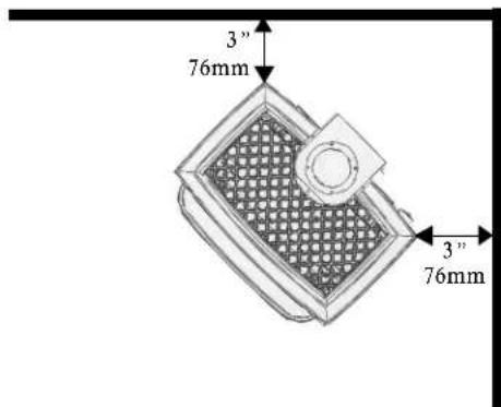
Corner clearance =3"(76mm)
(measured from rear corners)
Right side clearance = 4"(102mm)
Left side clearance = 10" (255mm)
(for access to the lighting instructions)
All venting components must be installed in accordance with the terms of their listing and manufacturer's instructions. Refer to the pipe manufacturer's instructions for proper pipe clearances. Any horizontal venting requires a 2" (50mm) top clearance off top of pipe.
ALCOVE
Minimum Alcove Width = 41"(1042mm)
(minimum side clearance in an alcove becomes 8" on right side of stove and 10" on left side of stove).
Maximum Alcove Depth = 24"(610mm)
Minimum Alcove Height (off stove)= 18"(460mm)
(minimum height off top casting of stove).
Pipe clearances = see manufacturer's listing.
PARALLEL INSTALLATION

CORNER INSTALLATION
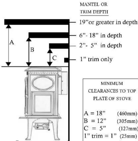
MANTEL, CEILING AND TRIM
VENTING REQUIREMENTS:
The Allagash is specifically designed to operate using 4" Type B vent pipe components or a Listed Flexible gas liner.
FOLLOW THE GUIDELINES LISTED BELOW FOR THE PROPER VENTING OF THE ALLAGASH B-VENT STOVE!
- All venting components must be installed in accordance with the terms of their listing and manufacturer's instructions.
- The minimum height of a vertically terminated system shall be no less than 7', and the maximum height shall be no more than 35'. See diagrams page 9.
- With steep roofs, nearby trees, and in predominant windy conditions, poor draft or down draft conditions can occur. In these cases, increasing the height of the vent or high wind termination caps may improve the situation.
- ELBOWS: If an offset or elbow is necessary in the vertical rise, it is important to support the vent pipe every three feet, to avoid excessive stress on the offsets.
- Whenever possible use 45^ elbows opposed to 90^ elbows. This offers less restrictions for the flow of flue gases. Maximum number of 90^ elbows = three Maximum number of 45^ elbows = four
- TOTAL MAXIMUM HORIZONTAL RUN ANYWHERE IN THE VENTING CONFIGURATION IS 4 FEET. The distance between any 45^ elbows is considered a horizontal run. See diagrams page 9.
- Any Type B vent passing through a roof must have a flashing, storm collar, thimble and a Type B cap is required. See diagrams page 9.
- Venting on the Allagash CANNOT be less than 4" in diameter or greater than 4" in diameter.
- Any UNUSED flue or masonry enclosure can be used as a passage way for venting the Allagash: PROVIDED the flue is relined using Type B 4" vent or Listed Flexible Gas Liner.
- The remaining space around the liner in a masonry or zero-clearance flue CANNOT be used to vent any other appliance.
- When terminating through the roof refer to the Gas Vent Rule for proper vent termination height. See Figure 1.

other
Roof Pitch Flat to 7/12 1.0 Over 7/12 to 8/12 1.5 Over 8/12 to 9/12 2.0 Over 9/12 to 10/12 2.5 Over 10/12 to 11/12 3.25 Over 11/12 to 12/12 4.0 Over 12/12 to 14/12 5.0 Over 14/12 to 16/12 6.0 Over 16/12 to 18/12 7.0 Over 18/12 to 20/12 7.5 Over 20/12 to 21/12 8.0 Vent less than 8' from wall MINIMUM HEIGHT ABOVE ROOF x Roof pitch is X/12
DO THIS
Vent less than 8 feet from wall:
locate vent termination 2 feet above wall
Figure 1
- NO venting can terminate horizontally or below roof eaves.
• Passage through combustibles (walls, ceilings) must be with Type B venting and must maintain listed clearances. - It is recommended that any horizontal runs have an upward slope of 1/4" per foot toward the termination cap.
- When venting through a thimble into a masonry flue any venting exposed in the room must be Type B venting.
-
Listed Flexible Gas Liners may not be exposed in any living space.
-
When decorative 6" pipe is installed to cover the venting any Listed Flexible Gas liner must be connected directly to the stove's draft hood.
- Use of single wall connector pipe as a vent is prohibited for use with the Allagash B-Vent stove.
• A firestop is required at every floor. - Any venting that is exposed above the first floor, regardless of attic space or living space, must be enclosed. Always maintain the required clearance from all sides of the vertical vent system according to manufacture.
• Installation of any components not manufactured or approved by Jøtul or failure to meet all clearance requirements will void all warranties and could result in property damage, bodily injury, or serious fire. - Never modify any venting component, or use any damaged venting product.
• THE GAS APPLIANCE AND VENT SYSTEM MUST BE VENTED DIRECTLY TO THE OUTSIDE OF THE BUILDING, AND NEVER ATTACHED TO A CHIMNEY SERVING A SOLID FUEL OR GAS BURNING APPLIANCES. - BE SURE TO MAINTAIN THE PROPER CLEARANCES TO COMBUSTIBLES AS DEFINED IN THIS MANUAL AND IN THE INSTRUCTIONS PROVIDED WITH EACH VENTING COMPONENT.
- When installing at an altitude above 2000' the minimum vertical rise becomes 12' from the draft hood.
- If more than two feet of venting is exposed to the outside, the entire exterior vent system must be enclosed in an insulated chase system.
Allagash B-Vent gas stove vented into a masonry or prefabricated fireplace.
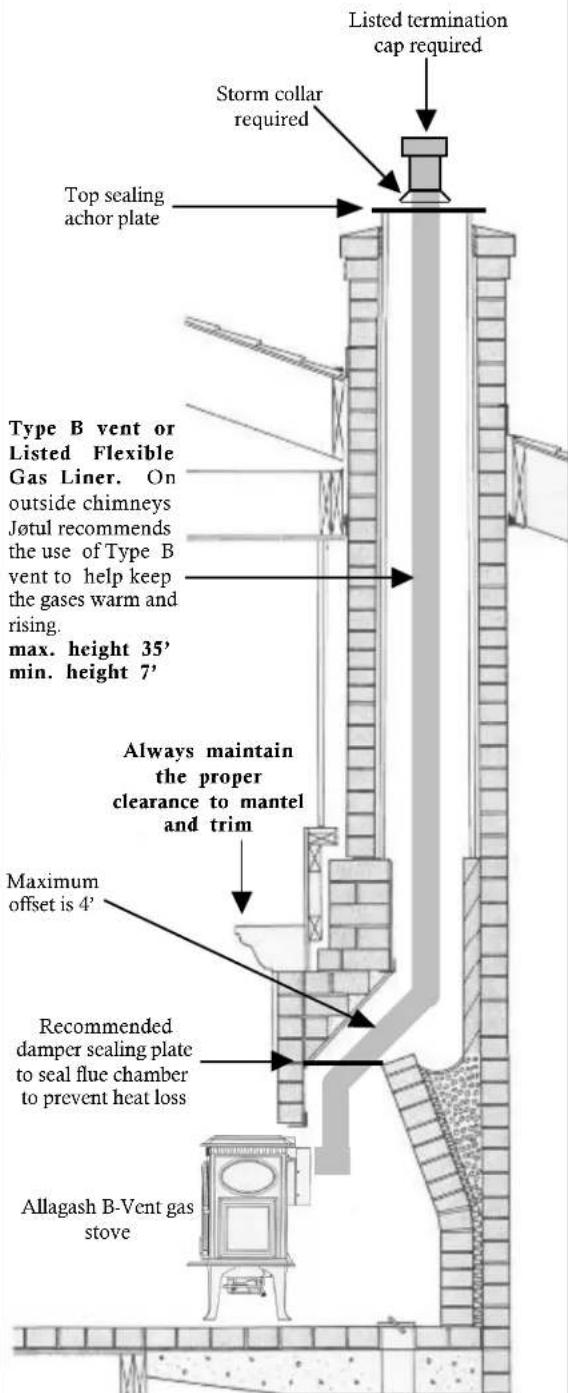
WARNING: FAILURE TO POSITION THE PARTS IN ACCORDANCE WITH THIS DIAGRAM OR FAILURE TO USE ONLY PARTS SPECIFICALLY APPROVED WITH THIS APPLIANCE MAY RESULT IN PROPERTY DAMAGE OR PERSONAL INJURY.
VENTING CONFIGURATIONS FOR THE ALLAGASH B-VENT

Minimum chimney on the Allagash B-Vent top vent or rear vent = 7 feet.
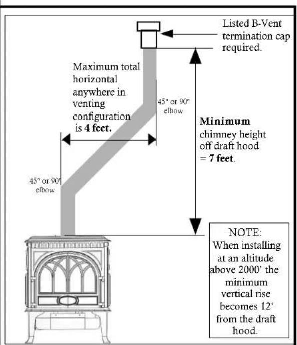
Maximum horizontal offset anywhere in venting configuration; rear vent or top vent directly on the stove or further up 45^ or 90^ elbows = 4 feet.


GAS CONVERSION:
The Allagash B-Vent gas stove is shipped from the factory equipped as a NATURAL GAS unit; However, the stove is shipped with the necessary gas conversion kit to convert the stove to burn PROPANE GAS. These kits contain all the necessary components needed to complete the task and ensure safe operation, including labeling that must be affixed to the stove.
WARNING:
THE CONVERSION KIT IS TO BE INSTALLED BY AN AUTHORIZED J∅TUL SERVICE TECHNICIAN IN ACCORDANCE WITH THE MANUFACTURER'S INSTRUCTION AND ALL CODES AND REQUIREMENTS OF THE AUTHORITY HAVING JURISDICTION. FAILURE TO FOLLOW THESE INSTRUCTIONS COULD RESULT IN SERIOUS INJURY OR PROPERTY DAMAGE. THE QUALIFIED AGENCY PERFORMING THIS WORK ASSUMES RESPONSIBILITY FOR THIS CONVERSION.
IN CANADA:
THE CONVERSION SHALL BE CARRIED OUT IN ACCORDANCE WITH THE REQUIREMENTS OF THE PROVINCIAL AUTHORITIES HAVING JURISDICTION AND IN ACCORDANCE WITH THE REQUIREMENTS OF THE CAN1-B149.1 AND .2 INSTALLATION CODE.
1/4" Nut driver, 7/16" and 1/2" open end wrench or deep well socket, 4mm allen wrench, Torx t20 or slotted screwdriver.
Included in the conversion kit:
1 regulator tower labeled for propane
3 regulator tower screws
1 burner orifice (#54 LPG)
1 pilot orifice (#30 for LPG, #51 for NG)
Label A - to be completed and adhered to the back of the stove.
Label B - to adhere to the stove's rating plate.
IMPORTANT:
If the forced air blower kit is installed, be sure to unplug blower before proceeding with this conversion. Any gas supply must be turned off and disconnected from the valve.
Conversion instructions are also shipped in the stove with the conversion kit.
Gas Conversion Procedure
- Turn off gas supply to the stove.
- Lift off top plate (5).
- Release the glass clips atop the stove and slowly lift glass panel (10) up and out of track.
- Remove the log set (12) using care not to scratch or damage logs.
- Lift out the log support (14). Remove the air divider (15) by lifting the right side and slowly rotating forward.
- Remove burner tube (13): Using a 14 " nut driver remove the two screws securing the burner tube (13) to the stove bottom. Lift out the burner tube.
-
Change the main burner orifice. Using a 12 " open end wrench or deep well socket remove the burner orifice and replace with the appropriate orifice, supplied in the kit.
-
Adjust the air shutter on the burner tube to allow for the proper mixing of air and gas. See Figure 2. The correct settings: natural 1/4" open propane 1/4" open

WHEN RE-INSTALLING THE BURNER TUBE BE SURE THAT THE TUBE IS PULLED FORWARD IN THE MOUNTING HOLES, SECURE WITH THE TWO 1/4" SCREWS.
- Change the pilot orifice. FROM WITHIN THE FIREBOX, PULL THE PILOT HOOD OFF THE PILOT ASSEMBLY. Using a 4mm allen wrench thread out the pilot orifice (counter clockwise). Replace with the appropriate orifice: See Figure 3.
51or natural gas
30 for propane
Tighten orifice into the base of the pilot assembly. Be sure the orifice is threaded tightly and flush with the base.
- Replace pilot hood onto pilot assembly.

Figure 3.
-
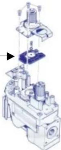
Change the variable regulator on the valve (Hi/Lo knob). Using a Torx t-20 screwdriver, remove the three specialty screws from the front of the valve regulator. See Figure 4.
-
Remove the regulator tower and the gasket. BE SURE TO REMOVE THE BLACK RUBBER GASKETS FROM THE VALVE!!! See Figure 4.
-
Install the new variable regulator tower with the new rubber gasket.
Thoroughly tighten new regulator to valve body.
BE SURE TO REMOVE THE BLACK RUBBER GASKET FROM THE VALVE!!!
natural_image
Mechanical assembly diagram showing exploded view of a valve mechanism (no text or labels)Figure 4.
-
Install the identification labels to the stove so that they can be seen by any person that may be servicing the stove.
-
Reassemble the stove, apply gas to the system and check for gas leaks including all stove lines before and after the valve.
NEVER USE AN OPEN FLAME TO CHECK FOR GAS LEAKS.
ATTENTION!! ATTENTION!! This is very important
Correct gas pressure is essential for efficient and safe operation of the Allagash B-Vent gas stove. It is important that the correct gas pressure be established at the time of the installation. For more details, see the Gas Pressure section of this manual on page 13.
ALWAYS REFER TO THE LIGHTING INSTRUCTIONS ON PAGE 23 OF THIS MANUAL WHEN LIGHTING YOUR ALLAGASH.
MAKING THE GAS CONNECTION:
NOTE: IF THE OPTIONAL FORCED BLOWER KIT (PART # 129161) IS TO BE INSTALLED ON THE STOVE AT THE TIME OF THE INSTALLATION OR IN THE FUTURE, THE GAS SUPPLY LINE SHOULD BE INSTALLED AS CLOSE TO THE FLOOR AS POSSIBLE.
USE OF A 90° ELBOW DIRECTLY OFF THE VALVE WILL ALLOW FOR PROPER CLEARANCE FOR THE BLOWER.
The gas supply line connection is made to the valve just inside the left rear leg. The Gas supply line should be a minimum of 3/8" in diameter, or the appropriate size to provide sufficient gas pressure to the valve regardless of the input setting.
The use of Flexible Gas Appliance Connectors is acceptable in many areas in the U.S.; However, Canadian methods vary depending on local code.
ALL INSTALLATIONS MUST COMPLY WITH LOCAL CODE OR IN THE ABSENCE OF LOCAL CODE, MUST COMPLY WITH THE MOST RECENT EDITION OF THE NATIONAL FUEL GAS CODE ANSI Z223.1/NFPA 54 OR CAN-B149.
All codes require: a gas shut-off valve (gas cock) and union, to be installed in the supply line, and in the same room as the appliance. This allows for the disconnection of the stove for servicing and maintenance. See Figure 5.

T-handle gas cocks are required in Massachusetts in compliance with code 248CMR.
Secure all joints tightly using appropriate tools and sealing compounds (for propane units, be sure to use compounds that are propane resistant). Turn on gas supply and test for gas leaks using a soapy water solution. Never use an open flame to check for leaks.
Leak test:
- Mix a 50-50 solution of water and dish soap.
- Light appliance- see lighting instructions on page 23 of this manual or on the stove's rating plate.
- Brush or spray all joints and connections with the soapy water solution.
- If bubbles appear at any connection or seam or a gas odor is detected, immediately turn gas control knob to the OFF position.
Tighten or reconnect the leaking joint and retest for any gas leaks.
GAS PRESSURE:
Correct gas pressure is essential for efficient and safe operation of the Allagash gas stove. It is important that the correct pressure is established at the time of the installation.
Proper gas pressure provides a consistent flow of gas to the appliance and is instrumental in checking for gas leaks. The gas control valve on the stove is equipped with pressure test points for gauge connections. The gauge connections are located on the front of the valve under the On/Off/Pilot-knob. Gauge connections are identified by:
E for inlet or supply pressure (the amount of gas coming to the valve.)
A for manifold pressure (the amount of gas that is coming out of the valve to the burner.)
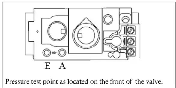
The appliance must be isolated from the gas supply line by closing its individual manual gas shut-off valve (gas cock) during any pressure testing of the gas supply piping system that is equal to or exceeds pressures of 1/2 psig (3.5kPa).
NECESSARY INLET GAS PRESSURES (inches water column)
MIN MAX
NATURAL GAS 5.0 WC 7.0 WC
PROPANE 11.0 WC 13.5 WC
NECESSARY MANIFOLD PRESSURES (inches water column)
MIN MAX
NATURAL GAS 2.2 WC 3.5 WC
PROPANE 6.5 WC 10.0 WC
ALWAYS TEST PRESSURES WITH VALVE CONTROL KNOB SET ON HIGH
Symptoms of incorrect gas pressure include:
Insufficient gas pressure:
- Small pilot flame which can result in insufficient millivolts.
- Little variation in flame picture between HI and LO settings.
- Insufficient gas to support more than one appliance causing nusance outages or gas surges.
Excessive gas pressure:
- Permanent damage to valve causing complete appliance shut down.
- Too large a pilot flame resulting in over heating of the power generator causing shut down.
- Sooting due to impingement and/or incorrect fuel to air mix.
HIGH ALTITUDE INSTALLATIONS:
When installing the Allagash in high altitude (above 2000') situations it becomes necessary to compensate for the thinner air (less volume of air per cubic foot). Higher altitudes effect the atmospheric pressure and heat value of gaseous fuels. The lower oxygen content in the air and the lower gas viscosity require the use of a different orifice to achieve efficient, clean combustion at the burner tube.
In the U.S.
THE DERATING KIT MUST BE INSTALLED BY AN AUTHORIZED SERVICE TECHNICIAN IN ACCORDANCE WITH THE MANUFACTURER'S INSTRUCTIONS AND ALL CODES AND REQUIREMENTS OF THE AUTHORITY HAVING JURISDICTION. THE INFORMATION STICKER MUST BE FILLED OUT BY THE INSTALLER AND ADHERED TO THE APPLIANCE AT THE TIME OF THE CONVERSION. THE QUALIFIED SERVICE AGENCY PERFORMING THIS WORK ASSUMES RESPONSIBILITY FOR THIS DERATING.
In Canada
THIS UNIT HAS BEEN TESTED FOR INSTALLATION AT HIGH ALTITUDES IN ACCORDANCE WITH CANADIAN TEST STANDARD CAN/CGA-2.17. THE DERATING SHALL BE CARRIED OUT IN ACCORDANCE WITH THE REQUIREMENTS OF THE PROVINCIAL AUTHORITIES HAVING JURISDICTION AND IN ACCORDANCE WITH THE REQUIREMENTS OF THE CAN1-B-149.1 AND .2 INSTALLATION CODE.
For installations from 2000ft.(610m) to 4500ft.(1370m) the orifice size for: natural gas is a #42 propane gas is a #55
SEE THE HIGH ALTITUDE ORIFICE CHART on page 14.
For high altitude installations consult the local gas distributor or the authority having jurisdiction for proper rating methods. If the installer must convert the unit to adjust for varying altitudes, the information sticker must be filled out by the installer and adhered to the appliance at the time of the conversion. See Figure 6.
Derating procedure
- To derate this unit, install the appropriate orifice per the High Altitude chart.
| EPVTSAG SIZE | EC IFIRO NOITAVEL PART # | ||
| RAN GAS | 33 | 0092)m046 | 411921 |
| GAS | #54 | 0092)m046 | 5416903 |
| RAN GAS | #42 | 2001'-4500')m076-1 kit | 673451 |
| GAS | #55 | 2001'-4500')m076-1 kit | P503057 |
- Remove the two 14 " hex head screws that hold the burner tube/log support to the bottom of the stove.
- Remove the burner tube/log support to expose the main burner orifice.
- Remove the orifice and replace with the appropriate one from the high altitude kit.
- Be sure to attach the high altitude conversion sticker provided with the kit to the rating plate on the appliance.
- It may be necessary to adjust the air shutter on the burner tube. See the AIR SHUTTER/FLAME APPEARANCE section of this manual for more details.
This sticker (shown below) is included in all high altitude kits and must be adhered to the stove whenever it is converted for high altitude installations.
| THIS STOVE HAS BEEN CONVERTED FOR USE AT AN ALTITUDE OF:_Orifice size_Manifold press._Input Btu/hr_Fuel Type_.Date of conversion_. |
Figure 6
AIR SHUTTER ADJUSTMENT/FLAME APPEARANCE:
THE ALLAGASH B-VENT GAS STOVE IS SHIPPED FROM THE FACTORY EQUIPPED AS A NATURAL GAS STOVE; THEREFORE, IT WILL BE NECESSARY WHEN USING THE STOVE WITH PROPANE GAS TO ADJUST THE AIR SHUTTER ON THE BURNER TUBE TO ACHIEVE THE PROPER GAS TO AIR MIX. See Figure 6.
The air shutter adjustment can also help achieve the desired flame appearance. Generally, flame appearance is a matter of preference, however most consumers enjoy the warm yellowish flame.
Closing the air shutter - will generate very long yellow flames resulting in soot. Sooting produces black deposits on the logs, on the inside walls of the appliance, and potentially on the exterior termination cap.
Sooting is caused by incomplete combustion in the flames and lack of combustion air entering the air shutter opening.
Opening the air shutter - will generate a flame that is blue and transparent, or an “anemic” flame. This flame is generally more efficient but not as pretty.
Jøtul recommends the following settings for the Allagash B-Vent gas stove: for use with propane 1/4" open for use with natural 1/4" open

ATTENTION: Air shutter should never be LESS than 1/8" open.
REMEMBER: Run the stove for a minimum of 15 to 20 minutes for an accurate representation of the flame appearance- this should be done before and between any air shutter adjustment.
To adjust the air shutter
- Remove the burner tube and using a phillips head screwdriver loosen the screw at the air shutter and adjust accordingly.
- Be sure to retighten the screw that holds the air shutter setting.
- Reassemble the stove and close the door, allow stove to burn 30 minutes on the HIGH setting, observing the flame continuously.
- If the flame appears weak, slow, or sooty, repeat the process described above until the flame is as desired.
WARNING: AIR SHUTTER ADJUSTMENTS SHOULD ONLY BE PERFORMED BY A QUALIFIED PROFESSIONAL SERVICE TECHNICIAN.
INSTALLING THE LOG SET:
The Allagash is equipped with a one piece log set and is packaged in bubble wrap inside the firebox. The log set must be removed from the packaging and arranged in the unit prior to start up of the gas stove. Do not handle the log set with your bare hands. Always wear gloves to prevent skin irritation from the ceramic fibers.
To install the log set, remove the packaging and place the log set inside the firebox, centered from left to right and completely against the rear wall of the stove. See Figure 8.
Embers: the stove is shipped with a package of glowing embers. These embers should be “pea size” and individually spaced across the burner tube screen. It is best to equally space these embers for optimum flame appearance. NOTE: YOU DO NOT HAVE TO USE ALL OF THE EMBERS.
THE CERAMIC FIBER LOGS AND GLOWING EMBERS CAN IRRITATE YOUR SKIN. IF THIS HAPPENS, GENTLY WASH HANDS WITH WARM SOAPY WATER.

natural_image
Illustration of a traditional-style gas stove with mountain landscape inside, labeled Figure 8 (no text or symbols on the stove itself)INSTALLING DECORATIVE PIPE
BRACKETS: (The use of decorative pipe is optional and not included with the Allagash B-Vent stove.)
To install the decorative pipe brackets on the Allagash simply remove the four 1/4" hex head screws holding the 4" flue collar on the stove. See Figure 9.
It is not necessary to remove the flue collar. Place the “L” shaped decorative pipe brackets on the flue collar and align the holes on the brackets, flue collar, and draft hood and secure all three with the four 1/4” hex head screws.
Black or enamel stove pipe can now rest on the the draft hood of the appliance while the brackets center the stove pipe over the draft hood.
Reminder: single wall stove pipe can never be used as the vent pipe on the Allagash B-Vent stove.

Figure 9
INSTALLING THE OPTIONAL BLOWER:
IMPORTANT: IF THE OPTIONAL FORCED AIR BLOWER KIT (part # 129161) IS TO BE INSTALLED ON THE STOVE AT THE TIME OF THE INSTALLATION OR IN THE FUTURE, THE GAS SUPPLY LINE SHOULD BE INSTALLED AS CLOSE TO THE FLOOR AS POSSIBLE. USE OF A 90° ELBOW DIRECTLY OFF THE VALVE WILL ALLOW FOR PROPER CLEARANCE FOR THE BLOWER.
Mounting the blower:
- Locate the reflector sheild (28) on the back of the stove. Remove the cover plate from the reflector shield to allow the blower bracket to slide under the stove.
- Locate the two raised bosses on the bottom plate (back) of the stove.
- The blower is mounted to the stove using these two threaded holes.
- With the blower bracket and sensor facing upward align the two middle mounting holes on the bracket with the two threaded holes on the bottom of the stove. See Figure 10.
- Use the two 6mm bolts to attach the blower to the stove.
- Be sure to tighten the bolts so that the blower is drawn upward and tight against the stove bottom.
- The heat sensor (thermodisc), that is already attached to the blower bracket, should be inserted under the stove bottom and make contact with the firebox! See Figure 10.

Connecting the blower wiring harness:
- Lift off the stove top plate.
- Loosen ( BUT DO NOT REMOVE) the 10mm bolt holding the switch box to the side of the stove (left rear corner of the stove), and lift out the switch box.
- Remove the "blank" switch from the box. (Hint: break the retaining tabs holding the switch in the box.)
- Insert the new HI/OFF/LO switch into the box.
- Connect the insulated wires from the blower to three leads on the HI/OFF/LO switch. BLACK wire to the HI position, WHITE wire to the OFF position, and the RED wire to the LO position. See Figure 11.
- Retighten the switch box to the side of the stove. Be sure all wires are unobstructed.
- Replace top plate.
REMINDER:
The blower will ONLY come on when the switch is in the Hi or Lo position and ONLY when the sensor (thermodisc) is heated by the stove.
(Approximately 10 - 20 minutes after the stove has been running).

Figure 11
INSTALLING THE OPTIONAL WALL THERMOSTAT OR REMOTE:
When installing a wall mounted thermostat to the Allagash, it must be a 750 millivolt DC two-wire circuit thermostat. The thermostat should be placed in the same room as the heater, typically 5' off the floor. Avoid drafty areas or any area that may effect the accuracy of the thermostat. The thermostat should be connected to the Allagash using a minimum of 16 gauge wire with a maximum length of 35 feet of wire.
Connect the two thermostat wire leads to the two lower terminals on the terminal block located directly above the ignitor button. Do not overtighten the connections. IT IS NOT NECESSARY TO DISCONNNECT ANY OTHER WIRES. See Figure 12.
For the thermostat to work the On/Off/T-Stat switch on the back of the stove must be in the T-stat position, and the pilot light must be running, as it is the power source for the thermostat.

flowchart
graph TD
    A["TH"] --> B["TP"]
    B --> C["TP"]
    C --> D["TH"]
    E["thermopile"] --> F["terminal block"]
    G["thermostat or remote control"] --> F
    F --> H["rocker switch"]
Figure 12
At the thermostat, the two wires should be connected to the two connections screws on the thermostat base plate per the manufacturer's instructions.
Remote: When using a remote, the remote receiver should be wired to the terminal block the same way the thermostat would be. See the instructions above.
SPILL SWITCH:
The Allagash B-Vent gas stove is equipped with a vent "SPILL SWITCH". This switch stops gas flow to the main burner in the event that the appliance is not vented or if the venting is blocked.
The spill switch is an important safety device located on the draft hood of the appliance and is wired directly to the thermocouple (power source for the stove). The “spill switch” is a bimetal sensor that is heat sensitive. In the event that the venting is not carrying the exhaust up and out, the heat from the exhaust will trigger the switch and stop the electrical current to the valve; thereby stopping gas flow to the main burner.
Spillage: Condition of flue gases failing to exit the venting system properly and instead flowing out of the relief opening of the draft hood and into the dwelling. Condition calls for immediate examination of the appliance and venting system and corrective action.
Source: HEARTH- Gas Training Manual
Spillage usually occurs due to incorrect vent size, or incorrect installation. Be sure to read all of the installation requirements addressed in this manual for the proper and safe installation of your Allagash B-Vent gas stove.
Unexplained outages can be the result of the “spill switch”. If you experience unexplained outages, contact your local Jøtul dealer for assistance.
ANY SERVICE TO THE SAFETY SPILL SWITCH MUST BE DONE BY A QUALIFIED SERVICE AGENCY.
CAUTION: LABEL ALL WIRES PRIOR TO DISCONNECTION WHEN SERVICING THE CONTROLS. WIRING ERRORS CAN CAUSE IMPROPER AND DANGEROUS OPERATION. ALWAYS VERIFY PROPER OPERATION AFTER SERVICING THE APPLIANCE.
ATTENTION: AU MOMENT DE L'ENTRETIENDES COMMANDES, ETIQUETEZ TOUS LES FILS AVANT LE DEBRANCHEMENT. DES ERREURS DE CABLAGE PEUVENT ENTRAIUN FONCTIONNEMENT INADEQUAT ET DAGEREUX.
CHECKING THE SYSTEM:
-
PURGING THE GAS LINE: When lighting the appliance for the first time it will take a few moments to clear the gas line of air. Once this purge is complete, the appliance will operate as described in the lighting instructions located on the stove's rating plate and the back cover of this manual. All subsequent lightings of the stove will not require such purging of the gas line.
-
PILOT FLAME: The pilot flame should be steady, not lifting or floating. The flame should be blue in color around the pilot hood, with traces of yellow toward the outer edges.
It is imperative that the pilot flame engulf the top 3/8" of the thermopile (power generator) and the top 1/8" of the quick drop out thermocouple. The pilot flame should project out of the pilot hood 1" at all three ports. See Figure 13.

Figure 13.
- BURNER ADJUSTMENT: The Jøtul Allagash gas stove is equipped with a variable gas control valve. This valve provides easy adjustment of the flame height appearance and heat output. To adjust the flame between the HI and LO setting, rotate the HI/LO knob, located in the center of the valve face. Flame height will adjust approximately 1.0" to 1.5" between the HI and LO settings. See Figure 14.
NO SMOKE OR SOOT SHOULD BE PRESENT. CHECK LOG PLACEMENT IF ANY SOOT OR SMOKE IS DETECTED. IF SOOT OR SMOKE PERSIST, THE AIR SHUTTER MAY NEED TO BE ADJUSTED.
See Air Shutter/Flame Appearance section of this manual for proper air shutter settings and adjustments (page 14). Note: the more offsets on the vent system, the greater the need for an air shutter adjustment.
CAUTION: DO NOT ATTEMPT TO ALTER THE FLAME APPEARANCE BY POSITIONING THE GAS VALVE IN ANY OTHER POSITION OTHER THAN THE FULL "ON" POSITION.

Figure 14
Flame appearance on the high setting after approximately 15 to 20 minutes burning.

WARNING: AIR SHUTTER ADJUSTMENTS SHOULD ONLY BE PERFORMED BY A QUALIFIED PROFESSIONAL SERVICE TECHNICIAN.
OPERATION OF APPLIANCE:
- The Allagash B-Vent gas stove is equipped with an On/Off/T-stat rocker switch or can be controlled using an optional wall-mounted thermostat. A separate switch is provided for the optional forced air blower kit.
- When lit for the first time, the Allagash will emit an odor for several hours. This odor is the burn-off by-products of internal paints and lubricants used in the manufacturing process.
- Condensation may occur on the glass upon each lighting of the appliance. This “fog” will disappear as the appliance heats up.
- Keep the controls and the area under the appliance free of debris, vacuum this area frequently. Always keep the appliance area clear and free from combustible materials, gasoline and other flammable liquids.
If and when a vacuum is used on any service for the stove, ALWAYS be sure the stove is cold and there are NO hot embers or sparks. - Remember, this appliance has a continuous burning pilot flame. Exercise caution when using products with combustible vapors.
- CAUTION: DO NOT OPERATE THIS APPLIANCE WITH THE GLASS REMOVED CRACKED OR BROKEN. REPLACEMENT OF THE GLASS SHOULD BE DONE BY A LICENSED OR QUALIFIED SERVICE PERSON. USE ONLY REPLACEMENT GLASS PROVIDED BY YOUR AUTHORIZED J∅TUL DEALER. NEVER USE ANY SUBSTITUTE MATERIALS.
WARNING:
OBSERVE CAUTION NEAR THE DOOR. THE GLASS PANEL MAY SHATTER UNEXPECTEDLY IF STRUCK WITH AN OBJECT. ALWAYS HANDLE THE GLASS PANEL WITH CARE. WHEN SERVICING THE STOVE ALWAYS PULL THE GLASS ASSEMBLY STRAIGHT UP FOR REMOVAL.
- Clean the glass only when necessary. Wipe surface with a clean, dampened, soft cloth. Follow with a dry, soft towel as desired. Take care not to scratch the glass surface.
WARNING:
DO NOT USE ABRASIVE CLEANERS ON THE GLASS. NEVER CLEAN THE GLASS WHEN IT IS HOT.
MAINTENANCE:
The Allagash B-Vent gas stove and its venting system should be inspected before use and at least annually by a qualified service technician.
IMPORTANT:
ALWAYS TURN OFF THE GAS SUPPLY TO THE STOVE AND UNPLUG THE OPTIONAL FORCED AIR BLOWER KIT IF INSTALLED, BEFORE ANY SERVICE WORK IS PERFORMED ON THE STOVE.
General cleaning: The firebox should be vacuumed out annually to remove any surface build up. Be sure to vacuum or wipe off the pilot assembly and burner orifice and burner tube. Also, when vacuuming the log set, be sure to handle it carefully as it is very fragile.
Gasket inspection: It is important that the glass gasket be inspected at least annually. Examine the rope gasket for signs of deterioration and make sure the gasket has a positive seal. This is important to prevent combustion gases from escaping into the room. Replace the gasket if necessary, refer to the replacement parts list on page 21.
To remove the glass panel or glass gasket:
- Lift off the stove top.
- Release the glass clips atop the firebox.
- Pull the glass frame assembly straight up and out of the stove.
- Lay the assembly on a flat surface and lift the metal tabs that secure the glass panel to the frame.
- Install the new glass panel and gasket in the glass frame and secure with metal tabs. Do not over tighten tabs as this could break the glass.
ALWAYS USE J∅TUL AUTHORIZED PARTS. NEVER USE ANY SUBSTITUTE PARTS.
Always replace any damaged or broken parts on the Allagash with J∅TUL AUTHORIZED PARTS ONLY. These are available through your Autorized Jøtul dealer. Never use any substitute parts on your Allagash B-Vent gas stove.
The Allagash and its venting system should be inspected annually or semi-annually by a qualified service person or agency.
With proper care and maintenance, your appliance will provide you with years of enjoyment. If you experience any problem or inconsistency with your Jøtul Allagash B-Vent gas stove, contact your authorized Jøtul dealer for assistance.
To expedite the proper service for your appliance the following information will help your dealer determine what you will need for parts and service.
RETAIN THIS MANUAL FOR REFERENCE AND MAKE IT AVAILABLE TO ANYONE USING OR SERVICING THE STOVE.
MODEL NAME: Allagash B-Vent Stove
SERIAL NUMBER:
DATE OF PURCHASE:
AUTHORIZED DEALER:
NAME OF INSTALLER:
TYPE OF FUEL:
WAS STOVE CONVERTED?
NOTES:
SERVICE LOG:
First Year
Name of Technician
Company Name____
Date of service ____
Work Performed
SERVICE LOG:
Two Year
Name of Technician
Company Name____
Date of service ____
Work Performed
SERVICE LOG:
Third Year
Name of Technician
Company Name____
Date of service ____
Work Performed
ALLAGASH B-VENT PARTS LIST
Cast Iron Parts / Enamel Colors
| PART | MATTE | BLU/BLK | IVORY | GREEN | INDIGO | |
| 1 | Left Door | 10390392 | 10390327 | 10390329 | 10390332 | 10390336 |
| 2 | Right Door | 10390492 | 10390427 | 10390429 | 10390432 | 10390436 |
| 3 | Front Panel | 10390192 | 10390127 | 10390129 | 10390132 | 10390136 |
| 4 | Side Panel | 102967 | 102033 | 102246 | 10203232 | 103128 |
| 5 | Top | 10390292 | 10390227 | 10390229 | 10390232 | 10390236 |
| 6 | Bottom Plate | 10390092 | 10390027 | 10390029 | 10390032 | 10390036 |
| 7 | Legs Single | 10192592 | 101966 | 102251 | 10192532 | 103123 |
| Short Leg Set | 350074 | 350075 | 350117 | 35007432 | 35007465 | |
| * | Top Cover | 10406592 | 10406527 | 10406529 | 10406532 | 10406536 |
9 Door Pins 125960
10 Glass Clips 129135
11 Glass Assembly 154337
* Glass Panel only 129113
* Gasket only (7/16 tadpole) 129124 (6ft.)
12 Log Set 129122
13 Burner Tube 129121
* Embers 129123
14 Log Support 129132
15 Air Divider 129320
16 Air Deflector 129109
17 Exhaust Baffle 129310
18 Firebox 129180
* Latch Keeper 129149
19 Heat Exchanger Gasket 129313
20 Heat Exchanger 129186
21 Draft Hood, Lower 129184
22 Draft Hood, Upper 129185
23 Flue Starter Collar 129189
24 Cover Plate Draft Hood 129183
25 Rear Shroud 129179
26 Spill Switch 129449
* Wiring Harness -Spill Switch 154350
* Spill Switch Wire - 32 in. 154389
* Spill Switch Wire - 35 in. 154374
* Wire Tie 129157
27 Box, On/Off/T-stat 129148
* ON/OFFSwitch Only 129153
28 Reflector Shield 129175
29 Valance 129106
* Wiring Harness -On/Off Switch 154319
30 Spud Plate Assembly 154346 NG
* Orifice Holder 129128
* Jam Nut for holder 129152
* Pilot Assembly NG 129471
* Gasket Pilot assembly 129116
* Pilot Orifice NG 129472
* Pilot Orifice LP 129473
* Pilot Line 129446
* Thermocouple 129447
* Thermopile 3094527
* Electrode with wire 129173
* Burner Orifice- NG 3/32 129114
* Burner Orifice- LPG #54 3096145
* Ignitor Button 3902573
* Ignitor Bracket 3902576
* B-Vent Valve NG 154915
* B-Vent Valve LP 154916
* Brass Elbow 129129
* Main Gas Line (complete) 154372
* Terminal Block 129154
* not illustrated
Hardware
| Leg Bolts (m6x20) | 117117 |
| Washer for Leg Bolts | 120004 |
| Bolt- Side Wall to Front (m6x20) | 117117 |
| Bolt- Front to Base (m6x20) | 117117 |
| Washer- Side to Front | 120004 |
| Washer- Firebox to Base | 120004 |
| Nut- Firebox to Base | 117910 |
| Side Clips Bolts (m6x12) | 117130 |
| Door Clip Bolts (m6x12) | 117130 |
| Valance Screws (#10x1/2) | 117917 |
| Door Washers | 11758 |
Accessories
| Conversion Kit to NG | 154375 |
| Conversion Kit to LP | 154348 |
| Wall Thermostat | 750003 |
| Blower Kit w/Rheostat | 129161 |
| Remote | 750002 |
| Screen | 129174 |
| Floor Bracket Kit | 750304 |
Only use replacement parts from an Authorized Jotul Dealer.
For the name of the dealer nearest you, call 207 797-5912
or write to:
Jotul North America
400 Riverside Street
Portland, ME 04104
GF3 BV Allagash Illustrated Parts Breakdown

LIGHTING INSTRUCTIONS
FOR YOUR SAFETY, READ BEFORE LIGHTING.
WARNING:
IF YOU DO NOT FOLLOW THESE INSTRUCTIONS EXACTLY, A FIRE OR EXPLOSION MAY RESULT CAUSING PROPERTY DAMAGE, PERSONAL INJURY, OR LOSS OF LIFE.
A. This appliance has a pilot which must be lit by hand. When lighting the pilot, follow these instructions exactly.
B. BEFORE LIGHTING, smell all around the appliance area for gas. Be sure to smell next to the floor because some gas is heavier than air and will settle to the floor.
WHAT TO DO IF YOU SMELL GAS:
- Extinguish any open flame.
- Open windows.
- Do not light any appliance.
- Do not touch any electrical switches.
- Do not use any phone in your building.
-
Immediately call your gas supplier from a neighbor's phone.
-
If your gas supplier cannot be reached, call the fire department.
C. Use only your hand to push in or turn the gas control knob. Never use tools. If the knob will not push in or turn by hand, do not try to repair it. Call a qualified technician. Force or attempted repair may result in a fire or explosion.
D. Do not use this appliance if any part has been under water. Immediately call a qualified service technician to inspect the appliance and to replace any part of the control system and any gas control which has been under water.
LIGHTING INSTRUCTIONS
- STOP! Read the safety information above.
- Access the lower controls.
- Turn the stove ON/OFF switch to "OFF", or set the thermostat to lowest setting (if used).
- Confirm that the gas supply line shut-off valve is open.
- Push in gas control knob slightly and turn clockwise to "OFF".
NOTE: Knob cannot be turned from "PILOT" to "OFF" unless the knob is pushed in slightly. Do not force.

CONTROL VALVE
-
Wait five (5) minutes to clear out any gas. If you then smell gas, STOP! Follow "B" in the safety information above on this page. If you do not smell gas, go to the next step.
-
Push in gas control knob slightly and turn counterclockwise to "PILOT".
-
Push in control knob all the way and hold in. Immediately light the pilot by triggering the spark ignitor (push the red button repeatedly) until pilot lights. Continue to hold the control knob in for about one minute after the pilot lights. Release knob and it should spring back. The pilot should remain lit. If it goes out, repeat Steps 5 through 8.
- If knob does not return when released, stop and immediately call your service technician or gas supplier.
• If pilot will not stay lit after several tries, turn the control knob

natural_image
Technical line drawing of a mechanical component with multiple ports and a cylindrical shaft (no text or symbols)PILOT ASSEMBLY
to OFF and call your service technician or gas supplier.
-
Turn gas control knob counterclockwise to "ON".
-
Turn the stove ON/OFF switch to "ON", or set thermostat (if used) to desired temperature.
TO TURN OFF GAS TO THE APPLIANCE:
- Turn ON/OFF switch to "OFF". The pilot will remain lit for normal service.
-
For complete shutdown, turn ON/OFF switch to "OFF".
-
Access the lower controls.
- Depress gas control knob slightly and turn clockwise to "OFF". Do not force.

Stoves and fireplaces must be installed to conform to local and national building regulations. Before preparing for the installation of the appliance, it is important that the instructions issued with the unit are carefully read an strictly adhered to. Jotul pursues a policy of constant product development. Products supplied may therefore differ in specification, color and type of accessories for those illustrated and described in the brochure.
400 Riverside Street
Portland, ME 04104
December 2000.4
129450
- WHAT TO DO IF YOU SMELL GAS:
- AVERTISSEMENT:
- QUE FAIRE SI VOUS SENTEZ UNE ODEUR DE GAZ.
- Model: Allagash B-Vent Gas Stove
- TABLE OF CONTENTS:
- THIS OWNER'S OPERATING AND INSTRUCTIONS MANUAL IS DESIGNED TO GIVE YOU A SAFE, EFFICIENT, DEPENDABLE INSTALLATION OF YOUR ALLAGASH B-VENT GAS STOVE.
- WELCOME TO J∅TUL:
- Input Rates
- STANDARDS:
- GENERAL INFORMATION:
- DO NOT OPERATE THIS STOVE IF ANY PART HAS BEEN UNDER WATER.
- Blower/Electrical Hazard
- LOCATION:
- FLOOR PROTECTION:
- STOVE CLEARANCES:
- ALCOVE
- PARALLEL INSTALLATION
- CORNER INSTALLATION
- MANTEL, CEILING AND TRIM
- VENTING REQUIREMENTS:
- FOLLOW THE GUIDELINES LISTED BELOW FOR THE PROPER VENTING OF THE ALLAGASH B-VENT STOVE!
- VENTING CONFIGURATIONS FOR THE ALLAGASH B-VENT
- GAS CONVERSION:
- WARNING:
- IN CANADA:
- Included in the conversion kit:
- IMPORTANT:
- Gas Conversion Procedure
- 51or natural gas
- for propane
- ATTENTION!! ATTENTION!! This is very important
- MAKING THE GAS CONNECTION:
- GAS PRESSURE:
- NECESSARY INLET GAS PRESSURES (inches water column)
- NECESSARY MANIFOLD PRESSURES (inches water column)
- Insufficient gas pressure:
- Excessive gas pressure:
- HIGH ALTITUDE INSTALLATIONS:
- In the U.S.
- In Canada
- Derating procedure
- AIR SHUTTER ADJUSTMENT/FLAME APPEARANCE:
- WARNING: AIR SHUTTER ADJUSTMENTS SHOULD ONLY BE PERFORMED BY A QUALIFIED PROFESSIONAL SERVICE TECHNICIAN.
- INSTALLING THE LOG SET:
- INSTALLING DECORATIVE PIPE
- INSTALLING THE OPTIONAL BLOWER:
- Mounting the blower:
- Connecting the blower wiring harness:
- REMINDER:
- INSTALLING THE OPTIONAL WALL THERMOSTAT OR REMOTE:
- SPILL SWITCH:
- CHECKING THE SYSTEM:
- OPERATION OF APPLIANCE:
- MAINTENANCE:
- SERVICE LOG:
- First Year
- Two Year
- Third Year
- ALLAGASH B-VENT PARTS LIST
- LIGHTING INSTRUCTIONS
- FOR YOUR SAFETY, READ BEFORE LIGHTING.
- IF YOU DO NOT FOLLOW THESE INSTRUCTIONS EXACTLY, A FIRE OR EXPLOSION MAY RESULT CAUSING PROPERTY DAMAGE, PERSONAL INJURY, OR LOSS OF LIFE.
- TO TURN OFF GAS TO THE APPLIANCE:
Brand : JOTUL
Model : GF3 BV Allagash
Category : Wood stove