
C 450 Kennebec CF - Wood stove JOTUL - Free user manual and instructions
Find the device manual for free C 450 Kennebec CF JOTUL in PDF.


| Product Type | Wood Stove |
| Brand | Jøtul |
| Model | C 450 Kennebec CF |
| Fuel Type | Seasoned hardwood logs |
| Heat Output (BTU/h) | 70,000 |
| Efficiency | 75% |
| Emissions (g/hr) | 4.5 |
| Flue Outlet Diameter | 6 inches (15.2 cm) |
| Maximum Log Length | 20 inches (51 cm) |
| Dimensions (H x W x D) | 30.5 x 23.5 x 18.5 inches (77.5 x 59.7 x 47 cm) |
| Weight | 220 lbs (100 kg) |
| Material | Cast iron body with steel firebox |
| Viewing Area | Large ceramic glass window |
| Firebox Lining | Refractory bricks |
| Combustion System | Secondary combustion for clean burn |
| Installation | Freestanding, requires non-combustible hearth |
| Clearance to Combustibles | At least 36 inches (91 cm) from sides and rear, 48 inches (122 cm) from front |
| Maintenance | Daily ash removal; annual chimney cleaning |
| Safety Certification | UL and ULC listed |
| Warranty | Limited lifetime on cast iron, 5 years on steel parts |
Frequently Asked Questions - C 450 Kennebec CF JOTUL
User questions about C 450 Kennebec CF JOTUL
0 question about this device. Answer the ones you know or ask your own.
Ask a new question about this device
Download the instructions for your Wood stove in PDF format for free! Find your manual C 450 Kennebec CF - JOTUL and take your electronic device back in hand. On this page are published all the documents necessary for the use of your device. C 450 Kennebec CF by JOTUL.
USER MANUAL C 450 Kennebec CF JOTUL
Jøtul C 450 Kennebec Fireplace Insert V.2
natural_image
Line drawing of a room interior with a person opening a large screen, no text or symbols presentKennebec Clean Face
Installation and Operating Instructions for the United States & Canada
■ The Jøtul C 450 Kennebec fireplace insert is listed to burn solid wood only. Do not burn any other fuels.
■ Read this entire manual before you install and use this appliance.
■ Save these instructions for future reference and make them available to anyone using or servicing the fireplace insert.
This wood heater requires periodic inspection and repair for proper operation. See this manual for specific maintenance information. It is against federal regulations to operate this wood heater in a manner inconsistent with the operating instructions in this owner's manual.
Table of Contents
Standards and Safety Notices
Standards / Codes .... 3
Safety Notices ....4
Preparation 4
Unpacking the Firebox 4
Specifications
Jøtul C 450 kennebec Fireplace Insert....5
Accessories 5
Dimensions 5
Installation
Masonry Fireplace Requirements ....6
Factory-built Fireplace Requirements ....6
Chimney Height......6
Hearth Protection ....7
Clearance to Combustibles 8
Chimney Connection ....9
Firebox Installation 10
Surround Assembly 11
Blower Assembly 12
Blower Operation ....13
Blower Maintenance ....13
Operation
Combustion Efficiency 14
CO Emissions 14
Wood Fuel and Performance 14
Functionality ....14
Break-in Procedure....15
Air Control Settings....15
Starting / Maintaining the Fire....16
Adding Fuel 16
Formation of Creosote 16
Maintenance
Ash Removal 17
Glass Care and Replacement....17
General Maintenance....18
Gasket Replacement....18
Appendix A
Alternate Hearth Protection ....19
Appendix B
Alternate Mantel Clearances ....20
Illustrated Parts Breakdown
Exploded View 21
Parts Listing 22
Warranty Statement ......23
For Your Records...
Record the following information to help your dealer determine what you will need should your fireplace ever require parts or service. The serial number and manufacturing date are indicated on the permanent label located in the blower compartment under the firebox. You may also wish to attach your sales receipt to this manual for future reference.
Model: Jøtul C 450 Kennebec Fireplace Insert
Serial Number:
Purchase Date:
Dealer:
Phone:
Installed by:
Date:
PLEASE NOTE:
IT IS NORMAL FOR SMOKE AND ODOR TO OCCUR DURING THE INITIAL STAGES OF OPERATION, DEPENDING UPON TEMPERATURES GENERATED OVER TIME. THIS "CURING" CONDITION CAN BE ALLEVIATED BY PROMOTING FRESH AIR CIRCULATION WITHIN THE IMMEDIATE VICINITY OF THE APPLIANCE.
NATIONAL FIREPLACE INSTITUTE

CERTIFIED
www.nficertified.org
We recommend that our gas hearth products be installed and serviced by professionals who are certified in the U.S. by the National Fireplace Institute® (NFI) as NFI Gas Specialists.
Standards
The Jøtul C 450 Kennebec fireplace insert has been
tested and listed to the following standards:
U.S: ANSI/UL 1482-2011 and ANSI/UL 737-2011
Canada: CAN/ULC-S627-00 and ULC-S628-93
Certified Safety Tests performed by:
ITS, Intertek Testing Services
Middleton, Wisconsin
Manufactured by:
Jøtul North America
55 Hutcherson Drive
Gorham, Maine 04038-2644
Combustion Specifications
Heating Capacity: ^2 Up to 1,600 sq. ft.
Maximum Burn Time: ^2 Up to 9 hours
Combustion Efficiency: ^3 HHV LHV
72.57%
CO Emissions: ^4 107.09 g/hr
Pariculate Emissions: ^5 4.4 g/hr
Fuel: 20" Logs (508 mm)
78.42%
See the Operation section of this manual for important information regarding the safe, proper, and most efficient operation of your stove.
1 Heat Output Range results are determined during specific emissions tests established by the EPA.
The Maximum Heat Output value is representative of a more frequent re-fueling cycle than specified in the EPA High Heat Output test method.
^2 Heating Capacity and Maximum Burn Time will vary depending on design of home, climate, wood type and operation
^3 High Heat Value and Low Heat Value are obtained per CSA B415.1-10 test method. HHV calculation encompasses all products of combustion, including H2O condensation. LHV calculation includes H2O in its vapor state. Simply put, HHV assumes all the water component is in a liquid state (condensed) at the end of combustion and that heat recovered from condensation can be put to use.
4 Carbon Monoxide Emissions rate results from Test Method CSA B415.1-10.
- Particulate Emissions rate is obtained using EPA Test Method 28-5H.
WARNING!
THIS WOOD HEATER HAS A MANUFACTURER-SET MINIMUM LOW BURN RATE THAT MUST NOT BE ALTERED. IT IS AGAINST FEDERAL REGULATIONS TO ALTER THIS SETTING OR OTHERWISE OPERATE THIS WOOD HEATER IN A MANNER INCONSISTENT WITH OPERATING INSTRUCTIONS IN THIS MANUAL.
This heater meets the 2015 U.S. Environmental Protection Agency's emission limits for wood heaters manufactured after May 15, 2015. This appliance may not be sold after May 15, 2020.
Check Building Codes
When installing, operating and maintaining your Jøtul C 450 CB fireplace insert, follow the guidelines presented in these instructions, and make them available to anyone using or servicing the stove.
In the U.S., the National Fire Protection Association's Code, NFPA 211, Standards for Chimneys, Fireplaces, Vents and Solid Fuel Burning Appliances, or similar regulations, may apply to the installation of a solid fuel burning appliance in your area.
In Canada, the guideline is established by the CSA Standard, CAN/CSA-B365-M93, Installation Code for Solid-Fuel-Burning Appliances and Equipment.
Always consult your local building inspector or authority having jurisdiction to determine what regulations apply in your area.
THE JOTUL C 450 KENNEBEC FIREPLACE INSERT IS NOT APPROVED FOR USE IN MOBILE HOMES.
NOTE:
CONSULT THE AUTHORITY HAVING JURISDICTION IN YOUR LOCALE (SUCH AS MUNICIPAL BUILDING DEPARTMENT, FIRE DEPARTMENT, FIRE PREVENTIOIN BUREAU, ETC.) BEFORE INSTALLATION TO DETERMINE THE NEED TO OBTAIN A PERMIT.
Safety Notices
- BURN SOLID WOOD FUEL ONLY. DO NOT BURN ANY OTHER FUELS.
- DO NOT USE CHEMICALS OR FLUIDS TO START THE FIRE. DO NOT BURN Garbage OR FLAMMABLE FLUIDS.
- IF THIS ROOM HEATER IS NOT PROPERLY INSTALLED, A HOUSE FIRE MAY RESULT. TO REDUCE THE RISK OF FIRE, FOLLOW THE INSTALLATION INSTRUCTIONS. FAILURE TO FOLLOW THESE INSTRUCTIONS MAY RESULT IN PROPERTY DAMAGE, BODILY INJURY, OR LOSS OF LIFE.
- CONTACT THE LOCAL BUILDING OR FIRE OFFICIALS ABOUT RESTRICTIONS AND INSTALLATION INSPECTION REQUIREMENTS IN YOUR AREA. WHEN NOT ADDRESSED IN THIS MANUAL, OR BY LOCAL CODE AUTHORITIES, INSTALLATION SPECIFICATIONS AND REQUIREMENTS DEFER TO NFPA 211 OR CSA B 365.
- DO NOT CONNECT THIS FIREPLACE TO ANY AIR DISTRIBUTION DUCT OR SYSTEM.
• DO NOT USE GRATES OR ANDIRONS TO ELEVATE THE FIRE. BUILD FIRE DIRECTLY ON THE FIRECHAMBER FLOOR. - EXTREMELY HOT WHILE IN OPERATION! KEEP CHILDREN, CLOTHING AND FURNITURE AWAY. CONTACT WILL CAUSE SKIN BURNS.
- NEVER OPERATE THE FIREPLACE WITH A CRACKED OR BROKEN GLASS PANEL.
• Install smoke detectors in the living areas and bedrooms of your home. Test them regularly and install new batteries twice annually. When installed in the same room as the stove, a smoke detector should be located as far from the stove as possible to prevent it from sounding when adding fuel to the fire. - Avoid creating a low pressure condition in the room where the stove is operating. Be aware that operation of an exhaust fan or clothes dryer can create a low pressure area and consequently promote flow reversal through the stove and chimney system. The chimney and building, however, always work together as a system - provision of outside air, directly or indirectly to an atmospherically vented appliance will not guarantee proper chimney performance. Consult your local Jøtul authorized dealer regarding specific installation/performance issues.
Preparation
We strongly urge you to have your authorized Jøtul dealer install your new Jøtul C 450 Fireplace Insert.
- Check with local building officials to determine what permits may be required before installation.
- Notify your insurance company before installing this fireplace.
Unpacking the Fireplace
All firebox components of the Jøtul C 450 Fireplace Insert are contained within the crate on a single pallet. The Surround Kit is contained in the same crate. As you unpack the contents, inspect each item for damage. Notify your dealer of any damage such as dents, cracked glass, or broken bricks.
Contents:
- Firebox Assembly - including Firebricks, 18 installed
- Ash Lip - packed under firebox shroud
- Blower Hardware Bag
- Stove Hardware Bag
- Fireplace Conversion Notice Plate
- Door Handle (Stove Tool)
- Cast Iron Surround Assembly
Tools & Materials Required:
- work gloves
- safety glasses
- tape measure
- phillips screwdriver
- tin snips
- power drill
• High-temperature sealant - 1" (25 mm) masonry anchors or nails, two
-
10 x 1/2" sheet metal screws, three
- 10 mm open end wrench and socket with extension
Removing the Firebox from Pallet
- The ash lip is shipped on top of the firebox.
- Remove the screws that secure the firebox base to the pallet. These mounting tabs may be broken off the base as may be necessary to accommodate a very narrow fireplace.

Figure 1. Maximum Sleeve Adjustment
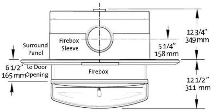
Figure 2. Minimum Sleeve Adjustment
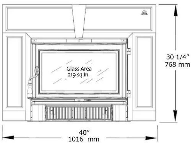
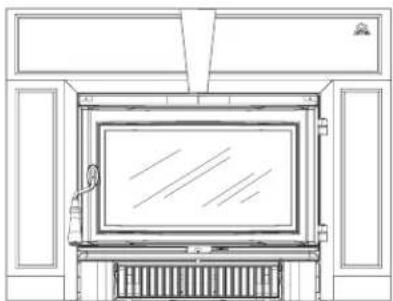
Figure 3. Overall Surround Dimensions are the same for both Kennebec Lattice and Clean Face versions.
Jøtul C 450 Specifications
Optional Blower: 125 cfm.
Shipping Weight: 445 lbs. (202 kg.)
Accessories
Steel Wide Surround / 47 3/4" x 34" #157213 Trimable Surround / 40" x 30" #157325 Mantel Heat Shield / Std. Cast Srnd. #155346 Mantel Heat Shield / Steel Wide Srnd. #157361 StoveGloves#157363 Universal Gasket Kit #157050

Figure 4. Flue Collar Centerline from Front Face
Installation
Masonry Fireplace Requirements
- The entire fireplace and chimney must be cleaned and inspected before installation. The system must meet local building code requirements.
- The structure and components must be free of any defects such as cracks or broken bricks or flue tiles. Any damage must be repaired before installation.
Any joint or gap that may exist between the hearth extension/fireplace facing and the fire chamber must be permanently sealed with medium-duty refractory mortar.
- The chimney must have a clay tile liner or a stainless steel liner utilizing a positive connection.
- DO NOT REMOVE BRICKS OR MORTAR FROM THE FIREPLACE OR CHIMNEY STRUCTURE. However, masonry or steel may be removed from the smoke shelf and adjacent damper frame area to accommodate installation of a chimney liner, provided that their removal will not weaken the structure of the fireplace or chimney, and will not reduce protection for combustible materials.
- CHIMNEY HEIGHT: Minimum - 15 ft. (4.57 meters) Maximum - 33 ft. (10.5 meters)
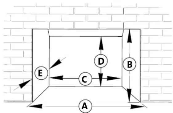
Minimum Fireplace Dimensions
A: FRONT WIDTH * 27 1/2" (698 mm)
B: HEIGHT 23" (584 mm)
C: REAR WIDTH 25 1/2" (648 mm)
D: REAR HEIGHT 21 1/2" (546 mm)
E: DEPTH 14" (355 mm)
* NOTE: Width dimension accommodates clearance for Surround attachment to the front of the firebox.
flowchart
graph TD
    A["A"] --> C["C"]
    C --> D["D"]
    D --> B["B"]
    B --> E["E"]
    E --> A
    style A fill:#f9f,stroke:#333
    style B fill:#bbf,stroke:#333
    style C fill:#dfd,stroke:#333
    style D fill:#dfd,stroke:#333
    style E fill:#dfd,stroke:#333
Figure 5. Minimum Fireplace Dimensions
Factory-Built Fireplace Requirements
The Jøtul C 450 may be installed into a factory-built fireplace with the following conditions:
- The factory-built fireplace must be listed per UL 127 or ULC S610.
- Installation must include a full height, listed chimney liner meeting type HT requirements (2100F) per UL 1777 (U.S.) or ULC S635 (CAN). The liner must be securely attached to the insert flue collar and the chimney top.
Some liner manufacturers require insulation in order to achieve a UL 1777 or ULC-S635 listing. Check with the manufacturer of the liner being used to determine if insulation is required. Insulation is recommended particularly if the chimney flue is located in a chase outside of the building envelope.
- The top plate of the liner system MUST NOT block the air flow between the cooling walls of the zero-clearance fireplace air-cooled chimney system. These cooling walls MUST remain open under all conditions to maintain proper circulation of cooling air.
- The damper or fireplace opening must be sealed to prevent passage of room air into the chimney cavity.
- The convection chamber and/or air circulation louvers of the zero-clearance fireplace MUST NOT be blocked-off. This requirement may preclude use of the cast iron surround panels. A custom-built surround panel system may be used provided it does not interfere with air circulation through the convection chamber.
- Alteration of the zero-clearance fireplace functionality or structure is not permitted; i.e. firebrick or refractory panels MUST NOT be removed to accommodate the fireplace insert installation. Alteration of the zero-clearance fireplace is limited to: a) removal of the damper for liner installation b) removal of external, nonfunctional trim which then must be stored within the fireplace for potential future re-assembly.
- Fireplace Conversion Notice PN 220508 must be permanently attached to the back of the fireplace. This metal label is included in the bag containing this manual.
- Means must be provide to properly support the front of the insert if it projects from the fireplace front. The weight of the insert must not compromise the structural integrity of the zero-clearance fireplace.
- Means must be provided to remove the insert or baffle to facilitate cleaning the chimney flue.
- Final approval is contingent on the authority having local jurisdiction.
Hearth Protection Requirements
The floor area in front of fireplace insert must be protected from live sparks and radiant heat.
- Materials: Hearth protection must be noncombustible insulating board, having an R value of 2.92 (0.343 K-value) such as Kaowool® 2600 #15 or the equivalent mortared masonry material. See Appendix A on page 19 for information how to calculate the R-value of alternative materials. Alternate protection must composed of materials as specified by NFPA 211.
- Protected Area: 18" Deep x 40" Wide A) Front - The protection must extend at least 18 inches (457 mm) forward from the door opening.
B) Sides - Protection must extend 20 inches (508 mm) to both sides of the centerline of the insert.
- Note that the firebox may extend out forward of the fireplace face depending on where the cabinet sleeve has been set to accommodate flue connection. Always measure hearth protection from the final, installed position of the firebox and the door opening. See figures 6 and 7.
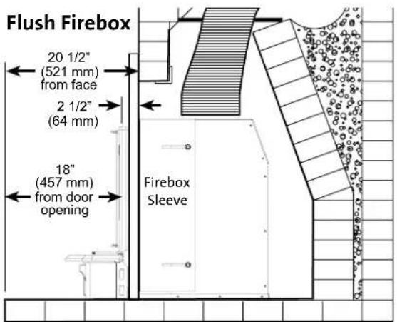
Figure 6. Sleeve adjustment results in minimum firebox extension forward of fireplace face.

Figure 7. Provide hearth protection to accommodate maximum firebox extension forward of fireplace face.
Clearance to Combustible Materials
These clearaces apply only to those C 450 inserts manufactured after December 2014 having serial numbers higher than 14250.
See Appendix B, page 20 for older units.
- There may be no combustible materials located anywhere within 36" (914 mm) of the front of the door.. This precaution includes items such as drapes or doors that could swing into the area within 36" of the insert.
- Clearance (open space) must be maintained between the fireplace insert and combustible materials located above and to the side. See figures 8-10 and Table 1 for minimum dimensions.
Mantel and Wall Clearances
Clearances are measured from the hearth surface, door opening, or centerline as noted in fig 8-10.
A: Hearth Protection:
Width from centerline.... 20" (508 mm)
B: Hearth Protection:
forward from the door opening ..... 18" (457 mm)
C: Side Trim - 6" max. depth, from centerline:
Firebox flush with fireplace face .... 22" (559 mm)
Firebox extended from fireplace face .... 27" (686 mm)
D: Side Wall - from centerline:
Regardless of Firebox position .... 27" (686 mm)
E: Upper Trim - Same as Mantel at Max. Depth 3 1/2" (90 mm) See Table 1.
F: Mantel - See Figures 9-10 and Table 1.

Figure 8. Clearance Diagram - No Heat Shielding
Mantel Clearance with Optional Heat Shield 155346
Clearance may be reduced as shown in Table 1. Maximum approved Mantel Depth is 11 1/2".
Clearance is measured from the hearth to the bottom of the mantel as illustrated.
Figure 9.
FLUSH FIREBOX

Figure 10.
EXTENDED FIREBOX

Table 1.
| Mantel Clearances - Serial Nos. after 14250 | ||||
| Flush Firebox Fig. 9 | Extended Firebox Fig. 10 | |||
| No Heat Shield | Heat Shield | No Heat Shield | Heat Shield | |
| A | 45"1143 mm | 40"1016 mm | 441118 mm | 41"1041 mm |
| B | 43 1/2"1105 mm | 38 1/2"978 mm | 42 1/2"1080 mm | 39 1/2"1003 mm |
| C | 42"1067 mm | 37"940 mm | 41"1041 mm | 38"965 mm |
| D | 40 1/2"1029 mm | 35 1/2"902 mm | 39 1/2"1003 mm | 36 1/2"927 mm |
| E | 39"991 mm | 34"864 mm | 38"965 mm | 35"889 mm |
Chimney Connection
A positive connection must be made between the fireplace insert and the chimney by one of the following approved methods.
In the U.S:
The insert is connected to a listed stainless steel flexible connector that extends beyond the chimney flue tile liner. A sealed block-off plate must be installed at the damper area of the existing fireplace. See fig. 11.
For internal chimneys, (no sides of the chimney exposed to the outside below the roofline,) a positive connection to the first flue tile is acceptable provided the tile is no larger than 8" x 12". For external chimneys, (one or more sides are exposed to the outside below the roof line,) a positive connection to the first flue tile is acceptable provided the tile is no larger than 8" x 8".
A 6", 7", or 9" stainless steel liner, extending the full height of the chimney, is required for all installations where the flue tile is greater than 8" x 12" for internal chimneys, or 9" x 8" for external chimneys.
In Canada:
The insert must be installed with a continuous chimney liner of 6" (152 mm) diameter extending from the fireplace insert to the top of the chimney. The chimney liner must conform to the Class 3 requirements of CAN/ULC-S635, Standard for Lining Systems for Existing Masonry or Factory-Built Chimneys and Vents, or CAN/ULC-S640, Standard for Lining Systems for New Masonry Chimneys.
See fig. 11a.
Do not use aluminum or galvanized steel pipe for chimney connection components - these materials are not suitable for use with solid fuel.
Installation
-
Remove the existing damper and linkage components from the fireplace. Alternatively, you can wire the damper plate to lock it in the open position. Thoroughly clean the firebox and smoke shelf area with a wire brush.
-
If the fireplace has been modified to accommodate installation, use anchors or masonry nails to attach the metal Fireplace Conversion Notice Plate (PN 220508) to the back wall of the masonry fireplace firebox where it will be readily seen should the insert be removed.
-
Install the Flex Connection plate according to the manufacturer's instructions. The sealing plate may require trimming to accommodate your specific fireplace damper.

Installing the Firebox
- If appropriate, use 3" flexible noncombustible duct to connect an outside air inlet to the air inlet collar at the back of the firebox.
- With assistance, move the firebox into position within the fireplace and align the insert flue collar with the Adaptor Collar.
- Attach the flue connector pipe. Use a 1/8" bit to drill attachment holes into connector pipe at the three pilot hole locations in the firebox flue collar. Secure the flue connector pipe using three, #10 x 1/2" sheet metal screws.
- Adjust the position of the Firebox to ensure that the Surround Panel Hangers are flush with, or slightly proud of, the outside face of the fireplace. If the Hangers are set back from the face, you will be unable to engage the Surround Hanger Clips with the holes in the Hangers.
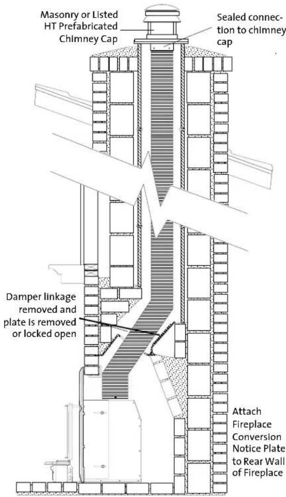
Figure 11a. Positive Chimney Connection - Canada.
Figure 12. Kennebec Classic Surround Panel Assembly

Kennebec Surround Assembly
All fasteners have already been installed in the appropriate locations at the factory. You will need to remove them, attach the parts together as described below and re-install the fasteners at those locations.
- Layout the parts. Place the castings face down on a protective surface such as carpeting, blankets or a sheet of cardboard. See fig. 12.
- Attach the Breastplates to each other. Use a 10 mm socket or wrench with two M6 x 10 hex head flange bolts.
- Attach the Leg plates. The Legs must be oriented with the Hang Tabs on the inside edges as shown in fig. 12. Use the two remaining M6 x 12 hex head flange bolts to attach the Legs to the Breastplate assembly.
-
Optional: If you will be installing the a Mantel Heat Shield, use the instructions included with that kit.
-
Attach the Assembly to the Firebox. Lift the entire assembly upright and position it in front of the insert firebox. The four Hang Tabs on the surround legs must engage with the adjacent holes in the two brackets on either side of the firebox opening. The surround will easily engage with these brackets if the firebox is slightly proud of the fireplace opening.
Hang the surround assembly on the firebox and push the entire unit into position so that the surround is flush against the fireplace face.
Final leg panel alignment can be adjusted by slightly loosening or tightening those attachment bolts as necessary.
Optional Surround Panels and Mantel Heat Shields
Follow the installation instructions supplied with these kits:
Steel Wide Surround / 47 3/4" x 34" #157213
Trimable Surround / 40" x 30" #157325
Mantel Heat Shield / for Standard Cast Surround #155346
Mantel Heat Shield / for Steel Wide Surround #157361

Figure 13. Blower hardware contents and orientation.
Blower Assembly
The blower is fully assembled, except for the wire harness connections which depend on what side you wish the power cord to be routed. The power receptacle, control switch, and snapstat assembly must all be installed on the same side. See fig. 13 for part orientation.
- Remove the Ash Lip if it has been installed.
- Remove the Base Grill. Use a 10 mm wrench to loosen the upper two M6 flange nuts at the back of the grill. The two lower nuts should already be loose. Lift the grill up to disengage it from the side ash lip supports.
- Remove the Ash Lip Support from the side where the power receptacle and switch will be installed. Use the 10mm socket with 6" extension to loosen the two nuts (A, Fig. 14) that secure the panel to the Base Plate.
-
Loosen the two hex nuts (B, Fig. 14) and pull the blower out of the firebox.
-
Remove the Blower Shroud with removal of two hex nuts (C, Fig.14) from the shroud legs.
-
Insert the Control Switch and Power Receptacle: Use a flat head screwdriver and pliers to pry the knockouts from the appropriate ash lip support. Work from the inside, to avoid marring the outside surface. Note the orientation of the Power Cord Receptacle for left and right side installation. Insert the Power Switch in the upper hole, and the Power Cord Receptacle into the lower hole. See fig. 15.
-
Install Snapstat Assembly: Remove the snap-stat knock-out from the same side of the Blower Shroud. Run the snapstat leads through that hole and attach the bracket to the Shroud using two #8
Hardware Bag Contents:
- Power Switch
- Power Cord Receptacle
- Snapstat Extension Assembly
- Air Deflector
-
8 x 1/2" sheet metal screws, 4
- Ground jumper wire
- Power Cord
Tools Required:
• safety gloves and goggles
- 10 mm wrench
- 10 mm socket w/ 6" extension
- 1/4" nut driver
- flat head screwdriver
- small pliers

Figure 14. Blower removal.

Figure 15. Remove knock-outs and install inserts. Note the difference in orientation for right and left side installation.
x 1/2" sheet metal screws. The clearance hole in the shroud leg is for screwdriver access. See fig. 13.
- Attach the Air Deflector: Using the two remaining #8 sheet metal screws, attach the Air Deflector to the Blower Shroud on the same side as the snapstat is installed. See fig. 13, parts 4 and 5.
- Re-attach the Blower Shroud to the firebox base using the two M6 x 12 flange head nuts previously removed. Confirm that the snapstat assembly is in direct contact with the firebox floor.
- Replace the blower and re-tighten the mounting nuts.
- Connect the loose wires as shown in fig. 16. Green: Remove the hex nut from the corner post and attach the ring terminals of the two ground leads to that post. Attach the jumper lead to the middle Power Receptacle terminal.
White: Wire harness to lower Power Receptacle Black: Wire harness to lower Switch terminal Red: Wire harness to upper Switch terminal
Beige:
- Snapstat to middle Switch terminal
-
Snapstat to upper Power Receptacle
-
Re-attach the Blower Shroud to the firebox base using the two M6 x 12 flange head nuts previously removed. Confirm that the snapstat assembly is in direct contact with the firebox floor.
- Replace the blower and re-tighten the mounting nuts.
- Replace the Ash Lip Support and tighten the nuts.
- Replace the Grill and Ash Lip.
- Plug the power cord into the receptacle and run the cord to the nearest house current outlet.

Figure 16. Wiring orientation.
THIS BLOWER MUST BE ELECTRICALLY GROUNDED IN ACCORDANCE WITH LOCAL CODES OR, IN THE ABSENCE OF LOCAL CODES, WITH THE CURRENT ANSI/NFPA 70, NATIONAL ELECTRICAL CODE OR CSA C22.1-CANADIAN ELECTRICAL CODE.
THIS UNIT IS SUPPLIED WITH A THREE-PRONG (GROUNDING) PLUG FOR PROTECTION AGAINST SHOCK HAZARD AND SHOULD BE PLUGGED DIRECTLY INTO A PROPERLY GROUNDED THREE-PRONG RECEPTACLE. DO NOT CUT OR REMOVE THE GROUNDING PRONG FROM THE PLUG.
ALWAYS DISCONNECT THE POWER SUPPLY WHEN PERFORMING ANY SERVICE ON THE FIREPLACE INSERT.
Blower Operation
The two-speed blower will enhance heat circulation around the firebox and out into the room. The blower is controlled by a heat activated switch (snapstat) that will ONLY function when the control switch is in either the HI or LOW setting. After the fire has been burning for a time, the snapstat will react to the heat and activate the blower, if the switch is in the HI or LOW position. Conversely, the blower will continue to operate until the snapstat cools as the fire wanes. The blower will then shut off automatically.
For best performance, do not turn the switch on until after the fire is well-established.
If the blower is not needed, place the blower control switch in the OFF position.
Blower Maintenance
In order to ensure that the blower delivers many years of reliable performance, you should inspect it regularly and clean it of any household dust and debris that may have accumulated. This is particularly important if there are any pets in the home.
ALWAYS DISCONNECT THE BLOWER FROM THE POWER SOURCE BEFORE CLEANING. Use a vacuum with soft brush attachment to clean the blower housing and compartment, as well as the area under the insert firebox.

Operation
Read the following section carefully before building a fire in your Jøtul C 450 Fireplace Insert.
Combustion Efficiency
The Jøtul C 450 has an EPA tested High Heating Value (HHV) efficiency rate of 72.57. There are aspects of efficiency that you should be aware of in order to get the most from your stove.
Operation habits and fuel moisture can have a significant effect on efficiency. Poorly seasoned wood having a higher than optimum moisture content, can reduce the amount of energy transferred to the living area as a result of the energy expended to evaporate the excess fuel moisture in order for the wood to burn. Operational aspects, such as not building a robust kindling fire to readily ignite the larger fuel pieces, can result in an inefficient smoldering fire. Additionally, most modern wood heaters' optimum performance and efficiency are at the medium to medium -low burn rates.
The location of the stove can have a significant effect on heating efficiency, primarily in regards to distribution of the heat. For example, a wood heater centrally located in the residence in an open living area will likely provide better circulation of heat than will a stove located in a room adjacent to the larger living area.
Minimize Carbon Monoxide Emissions
Testing the C 450 to CSA B414.1-10 measured carbon monoxide emissions at 107.09 g/hr. Most means of combustion produce some level of CO, including wood fires. Proper operation techniques, as outlined in this manual, will help ensure minimum emission output. Maintaining a well-established fire and avoiding operation that produces a smouldering, smoky fire, will greatly reduce CO levels.
It is highly recommended that a CO monitor (detector) be installed in the same room as the stove. The monitor, however, should be located as far away as possible from the stove to avoid alert soundings when adding fuel to the fire.
Wood Fuel and Performance
The C 450 is designed to burn natural wood only. Higher efficiencies and lower emissions generally result when burning air-dried, seasoned hardwoods, as opposed to softwoods, green or freshly cut hardwoods. Wood that has been air-dried for a period of 6 to 14 months will provide the cleanest, most efficient heat. Wood seasoned more than 2 years will burn too quickly to take advantage of the stove's low end efficiency strength.
A seasoned log will have check marks on the ends and be lighter than an unseasoned log which will show little or no check marks.
We recommend using a moisture meter to determine the moisture content of your wood. For purposes of home heating, your fuel should have a moisture content between 12 - 20%. Wood with higher moisture content will burn, however, very inefficiently. Most of its heat value will be lost to driving water out of the wood. Worse, that moisture will condense as creosote in the relatively cool chimney flue, increasing the potential for a chimney fire. Use of unseasoned wood defeats the purpose of any modern wood-burning stove.
DO NOT BURN:
- Coal;
- Garbage;
- Synthetic fuel or logs;
- Material containing rubber, including tires;
• Material containing plastics; - Waste petroleum products, asphalt products, paints, paint thinners or solvents;
- Materials containing asbestos;
- Construction or demolition debris;
- Railroad ties or pressure-treated wood;
- Manure or animal remains;
- Salt water driftwood or other previously salt-water; saturated materials;
- Unseasoned wood; or
- Paper products, cardboard, plywood, or particle board. (The prohibition against burning these materials does not prohibit the use of fire starters made from paper, cardboard, saw dust, wax or similar substances for the purpose of starting a fire.)
The burning of any of these materials can result in the release of toxic fumes, or render the heater ineffective and cause smoke. Never use gasoline, gasoline-type lantern fuel, kerosene, charcoal lighter fluid, or similar liquids to start or “freshen-up” the fire. Always keep such liquids away from the heater at all times.
C 450 Kennebec Functionality
When used with dry wood and a well-drafting chimney system, modern non-catalytic wood stoves burn fuel efficiently by the precise control and delivery of primary and secondary air to the fire. See fig. 18.
Primary Air is drawn into an inlet at the rear of the firebox and directed through a regulator shutter under the front door before entering the lower fire chamber. Additional primary air is directed to the top of the front door to act as an air wash which may prevent extreme soot build-up on the glass panel. The amount of primary air available to the fire determines the intensity of heat output and rate of fuel combustion; the greater the amount of air, the greater the heat output, the faster the wood burns. The primary air setting also determines the
effectiveness of the air wash over the glass; the higher the setting, the cleaner the glass will remain. Additional air is separately directed into the top of the fire chamber to support combustion of exhaust gasses before passing out of the stove. This unregulated Secondary Air enters through the inlet in the rear of the firebox and is heated as it passes over the back into a two-tiered manifold at the top of the firechamber. Volatile gases, released unburned from the fuel bed, rise to the baffle where they are turbulently mixed with the hot, fresh oxygen. Secondary combustion then occurs before the gases pass into the heat exchange chamber.
Air Control Settings
A single lever regulates the Primary Air flow that controls the intensity of the fire and consequent heat output and burn time. This lever is located within the slot on the upper right front of the fireplace insert. See fig. 19
When first starting or reviving the fire, the control lever should be set at the far right position to allow the maximum amount of air into the stove. See fig.15. After the fire is well-established, the lever should be set at position to moderate incoming air to maintain the desired long term heat output and/or burn time.
In general, the more air made available to the fuel will result in the hottest fire intensity and the fastest fuel consumption. Alternatively, the less air made available to the firebox will result in low heat output
Break-in Period
The cast iron parts of your fireplace insert require a break-in process to allow them to gradually adjust to thermal expansion and contraction. This is accomplished by building a series of three or four fires, each somewhat hotter than the last. Allow the fireplace insert to cool completely before building the next fire.
Limit the first fire to just kindling and a couple of 1-2 inch logs and add progressively more and larger logs to subsequent fires, keeping the Air Control set to the fully open position.
It is normal for a new fireplace insert to emit odor and possibly smoke during the first few fires. This is characteristic of the burn-off of residues from the manufacturing process and the curing of painted surfaces. Open a window near the fireplace insert to provide plenty of fresh air to the room during this “seasoning” period.
DO NOT OVER-FIRE THIS APPLIANCE. IF ANY PART OF THE INSERT OR CHIMNEY GLOWS RED, YOU ARE OVER-FIRING. A HOUSE FIRE OR SERIOUS DAMAGE TO THE STOVE OR CHIMNEY COULD RESULT. IF THIS CONDITION OCCURS, IMMEDIATELY CLOSE THE AIR CONTROL.

Figure 18. Air Flow Diagram.

natural_image
Line drawing of a closed storage unit with arched windows and ventilation grilles (no text or symbols)Figure 19. Air Control Setting
ALWAYS WEAR STOVE GLOVES WHILE TENDING THE FIRE.
NEVER ALLOW THE FIRE TO REST DIRECTLY ON THE GLASS. KEEP THE LOGS SPACED AT LEAST ONE INCH FROM THE GLASS TO ALLOW FOR PROPER AIR FLOW WITHIN THE STOVE. AVOID STRIKING THE GLASS.
OPERATE THE INSERT ONLY WITH THE DOOR FULLY CLOSED. OPERATION WITH THE DOOR PARTIALLY OPEN MAY RESULT IN OVER-FIRING. IF THE DOOR IS LEFT PARTIALLY OPEN, GAS AND FLAME MAY BE DRAWN OUT OF THE STOVE CREATING SAFETY RISKS FROM BOTH FIRE AND SMOKE
Starting and Maintaining a Fire
Burn only solid wood directly on the bottom grate of the stove. Do not elevate the fire in any way.
Traditional Fire Building
- With the primary air control lever in the full open position (to the right), start with several sheets of crumbled newspaper placed directly on the grate. On top of the newspaper, place several pieces of small dry kindling (approx. 1" in diameter) with two to three larger logs (approx. 3" to 5" in diameter) on top.
- Light the fire and close the door, slowly building the fire by adding larger and larger logs. Be sure to follow the break-in procedure before creating a hot fire that might damage the stove.
- Once the fire has become well established, adjust the primary air control lever as necessary to generate the desired heat output and burn time.
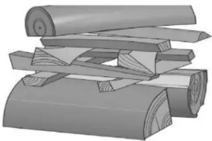
Top-Down Fire Building - See fig. 20.
Many people find this method to be superior to the traditional method.
- With the primary air control lever in the full open position (to the right), place two short 1/4-split logs on the firebox floor, perpendicular to the rear wall, about 6 inches apart.
- Place kindling across the base logs.
- Place one or two smaller logs on top of the kindling.
- Place newspaper between the two bottom logs under the kindling. Light the news paper and close the door. Continue to add kindling and small logs as necessary to build the fire. Keep the air control fully open until the fire is well-established.
Adding Fuel to the Fire
When reloading the stove while a bed of hot embers still exists, follow this reloading procedure:
• Always wear stove gloves when tending to the fire.
- Push the Air Control Lever to the full open position (far right).
natural_image
Stacked wood logs with visible grain patterns and cutouts (no text or symbols)Figure 20. Top-down Firebuilding
- Wait a few seconds before opening the door. This allows the renewed air circulation to clear unburned gases from the firebox.
- Use a stove tool or poker to distribute the hot embers equally around the firebox.
- Load the fuel, usually with smaller logs first.
- Close the doors and secure the latch.
- Wait 5 – 10 minutes for the fire to re-establish before adjusting the Air Control Lever for the desired heat output. If a thick bed of live coals is present, you may be able to add fuel and immediately set the air control without waiting for the fire to be re-established.
Creosote Formation
The Jøtul C 450 is designed to burn wood cleanly and efficiently when operated as described in this manual. However, when wood is burned slowly and at low temperatures, tar and other organic vapors are produced which condense on the relatively cooler chimney flue surfaces to form creosote. Failure to keep the chimney system free of creosote build up could result in a chimney fire.
The creosote that accumulates in the chimney is highly flammable and is the fuel of chimney fires. To prevent chimney fires, it is important to have the chimney flue and connector pipe inspected every two months during frequent use and cleaned whenever accumulation of 1/4" or more is evident. A qualified chimney sweep or other authorized service person can provide this service.
It is also important to remember that chimney size, temperature and height all affect draft which in turn affects the formation of creosote. An exterior chimney, whether masonry or prefabricated steel, will be exposed to cold outside temperatures, and consequently, will be more prone to creosote accumulation than an interior flue.
A chimney flue located within the home interior will benefit from the insulating characteristics of the building itself. Consequently, the flue system will be less conducive to condensation of unburned gases and minimal creosote accumulation will result.
As a general rule, try to avoid burning the insert at the lowest air control settings. Although a low setting will prolong burn time, it may also result in incomplete combustion. In reducing the fire intensity, draft is weakened and the chimney flue cools. This, together with the increase in unburned gases, leads to rapid creosote accumulation.
Maintenance
Ash Removal
Always wear stove gloves when handling ashes.
Ash removal will be required periodically depending on how frequently the stove is used. Use a steel ash shovel and metal container with a tight-fitting lid. NEVER USE A PAPER OR PLASTIC BAG AS AN ASH RECEPTACLE.
The container of ashes should be placed on a noncombustible floor or on the ground, well away from all combustible materials, pending final disposal. If the ashes are disposed of by burial in soil or otherwise dispersed, they should be kept in the closed container until all coals and cinders have thoroughly cooled.
Glass Care
Cleaning
Occasionally it will be necessary to clean the carbon deposits and fly ash off of the glass. If deposits are allowed to remain on the glass for an extended period of time, the glass may become etched and cloudy.
Creosote deposits should burn off during the next hot fire.
- The Glass must be COMPLETELY COOL.
- Only use a cleaner that is specifically designed for this purpose. DO NOT USE ABRASIVE CLEANING AGENTS, OR THOSE CONTAINING AMMONIA. The use of abrasives will damage the glass, leaving a frosted surface. Ammonia will etch the glass to the same effect. Crumpled newspaper is an especially good cleaning material.
- Rinse and dry glass completely before lighting a fire.

Figure 21a. Single Door Glass Assembly Parts.
Glass Removal
Always operate the doors slowly and cautiously to avoid cracking or breaking the glass. Never use the door to push wood into the firebox. If the glass becomes cracked or broken follow the replacement procedure below.
IMPORTANT:
REPLACE GLASS ONLY WITH J∅TUL CERAMIC GLASS SPECIFICALLY DESIGNED FOR THE J∅TUL C 450 FIREPLACE INSERT:
PART #220356 (TWO) - FOR DOUBLE DOORS PART #222991 - FOR THE SINGLE DOOR DO NOT USE SUBSTITUTES. REPLACEMENT GLASS PANELS CAN BE ORDERED THROUGH YOUR J∅TUL DEALER.
NEVER OPERATE THE STOVE WITH A CRACKED OR BROKEN GLASS PANEL.
- Remove the door from the stove and place on a flat surface.
- Carefully remove all of the glass clips from the inside of the door. See fig. 21a for Single Door / fig. 21b for Double Doors.
- Gently remove all pieces of the glass panel and gasket.
- Remove all remaining debris from the glass area using a wire brush.
- Apply a small bead of gasket/stove cement and the new gasket. Do not overlap the ends of the gasket rope.
- Center the new glass panel over the gasket and reinstall the glass clips.
- It may be necessary to retighten the glass clips after the stove has burned and the gasket has been seated.
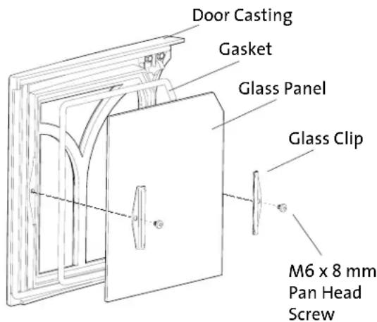
Figure 21b. Double Door Glass Assembly Parts.
General Maintenance
Regular maintenance will assure proper performance and prolong the life of your Jøtul C 450.
The following procedures do not take long and are generally inexpensive. When done consistently, they will help increase the life of your fireplace insert and assure satisfactory performance.
- Thoroughly clean the insert. Enamel surfaces should be cleaned with soap and water.
- Empty firebox of all soot and ashes. Never use a household vacuum cleaner to remove ashes. Only a shop vac with a metal container is acceptable and only when you are certain the ashes are cold.
- Inspect the firebox using a utility light inside and out for cracks or leaks. Replace all cracked bricks and repair leaks with furnace cement.
Removing the Insert for Annual Cleaning
U.S. Direct-connection Only:
- Lift the Ashlip from the Ashlip Extension.
- Remove the Surround Panel assembly by grasping the lower lip of the Breastplates and lifting it up and off of the firebox cabinet. There are four tabs that must be disengaged from the hangers on either side.
- Remove the three screws that attach the flue connector to the flue collar, and disengage the it from the insert.
- Pull the firebox and cabinet forward as a unit. The flue connector, liner, and chimney can now be inspected and cleaned.
- See the Installation section of this manual for reassembly procedures.
Canada Installations (Full Reline):
Remove the combustion baffle from the firebox by lifting it up and tilting it back down and out. The chimney can be swept directly into a bucket placed under the flue outlet.
Gaskets
Check door and glass gaskets for seal integrity.
The gaskets should be soft enough to be somewhat resilient to the touch. Over time, gaskets will compress and harden. Replace worn-out or hardened gaskets with the appropriate size material available from your local Authorized Jøtul Dealer.
To check the seal of the front doors, close and latch the doors on a dollar bill and slowly try to pull the dollar bill free. The seal is too loose if the bill can be easily removed. Adjust the door latch and test again.
Gasket Replacement
See the Parts List on page 21 to order the correct gasket material. Universal Gasket Kit #157050 is also available.
- Remove the old gasket material with a pliers and thoroughly clean the channel with a wire brush.
- Lay out the new gasket around the channel to determine length. Trim the gasket to leave 1" excess.
- Apply a small bead of furnace cement in the channel.
- Lightly press the new gasket into the channel, being careful to avoid compressing or stretching it. Trim the gasket further as necessary to allow the tail end to slightly overlap the other end.
- Wait ten minutes to allow the cement to set and then close and latch the doors. Reopen the doors and, using a damp cloth, wipe away any excess cement that may be squeezed out from under the gasket.
Firebricks
DO NOT OPERATE THE STOVE WITH BROKEN OR MISSING BRICKS.
See fig. 25, page 21 and the parts listing on page 22 for the configuration and part number of any firebricks that require replacement. Order through your local Jøtul Authorized Dealer.
Appendix A
Alternate Floor Protection
All floor protection materials must be non-combustible i.e.. metal, brick, stone, or mineral fiberboards. No combustible material may be used to protect the floor in front of the fireplace insert.
Follow this procedure to determine if a proposed alternate floor material meets the requirements listed in this manual.
R-value = Thermal Resistance
K-value = Thermal Conductivity
C-value = Thermal Conductance
- Convert the specification to R-value;
a. If R-value is given, no conversion is needed.
b. If K-value is given with a required thickness (t) in inches: R = 1/K X T.
c. If C-value is given: R = 1/C.
- Determine the R-value of the proposed alternate floor protector.
a. Use the formula in Step 1 to convert values not expressed as "R".
b. For multiple layers, add R-values of each layer to determine overall R-value.
- If the overall R-value of the system is greater than the R-value of the specified floor protector, the alternate is acceptable.
Example:
The specified floor protector should be 3/4" thick material with a K-factor of 0.84. The proposed alternate is 4" brick with a C-factor of 1.25 over 1/8 inch mineral board with a K-factor of 0.29.
Step A. Use formula above to convert specifications to R-value. R = 1/K × T = 1/.84 × .75 = .893
Step B. Calculate r of proposed system.
$$ \begin{array}{l} 4 ^ {\prime \prime} \text { brick of } C - 1. 2 5, \text { therefore } \ R \text { brick } = 1 / C = 1 / 1. 2 5 = 0. 8 0 \ 1 / 8 \text { " mineral board of } K = 0. 2 9, \text { therefore } \ R \text { mineral board } = 1 /. 2 9 \times 0. 1 2 5 = 0. 4 3 1 \ \text { Total } R = R \text { brick } + R \text { mineral board } = \ 0. 8 + 0. 4 3 1 = 1. 2 3 1 \ \end{array} $$
Step C. Compare proposed system R = 1.231 to specified R of 0.893. Since R is greater than required, the system is acceptable.
Definitions:
$$ \begin{array}{l} \text {ThermalConductance} = \ C = \quad B t u \underline {{\quad = \quad}} W \ \quad (H r) (f t 2) (f) \quad (m 2) (k) \end{array} $$
$$ \text { Thermal Conductivity } = \begin{array}{c} K = \underline {{\text { Btu }}} \ (\text { Hr }) (\text { ft2 }) (\text { f }) \end{array} = \underline {{\text { W }}} \quad \begin{array}{c} = \underline {{\text {(Btu)}}} \ (\text { m2 }) (\text { k }) \end{array} \quad \begin{array}{c} = \underline {{\text {(hr)}}} (\text { ft }) (\text { f }) \end{array} $$
Thermal Resistance =
$$ \begin{array}{c c c} \text {R = Btu} & = (\underline {{m 2}}) (k) & = (\text {Btu}) (\text {inch}) \ (\text {Hr}) (\text {ft2}) (f) & W & (\text {hr}) (\text {ft2}) (f) \end{array} $$
The Jøtul C450 Fireplace Insert requires floor protection having a minimum insulating R-value of 2.92.
Appendix B
These clearances apply only to Jøtul C 450 fireplace inserts built before December 30, 2014 and having serial numbers lower than 14251.
Hearth protection requirements are the same as specified on page 8 of this manual.
Minimum Clearances
Clearances are measured from the hearth surface, door opening, or centerline as noted below.
A: Hearth Protection, width from centerline.... 20" (508 mm)
B: Hearth Protection, forward from the door opening 18" (457 mm)
C: Side Trim, 1" max. thickness, from centerline .... 20 3/4" (527 mm)
D: Side Room Wall ....44 1/4" (1124 mm)
E: Mantel- with no Heat Shield:
3 1/2" (90 mm)....49 1/2" (1257 mm)
F: Mantel- with no Heat Shield:
12" (304 mm) max. depth - 55 1/2" (1410 mm)

Figure 22. Clearance Diagram - No Heat Shielding
Mantel Clearance with Optional Heat Shield 155346
Clearance may be reduced as shown in fig. 8b. Maximum approved Mantel Depth is 12".
Clearance is measured from the hearth to the bottom of the mantel as illustrated.

Figure 23. Mantel Clearances - measured from the hearth surface to the lowest mantel surface.

Figure 24. Mantel Clearances, with Mantel Heat Shield 155346 - measured from the hearth to the mantel.
Jøtul C 450 Fireplace Insert
Illustrated Parts Breakdown

Figure 25. See parts listing on next page.
No. Description Part Number
| 1. | Control Door, Vertical Grille - Matte Black | 157042 |
| Control Door, Vertical Grille - Blue Black | 157041 | |
| 2. | Ashlip - Matte Black | 10397992 |
| Ashlip - Blue Black | 10397927 | |
| 3. | Kenn. Surround Leg, Left - Matte Black | 10425992 |
| Kenn. Surround Leg , Left - Blue Black | 10425927 | |
| 4. | Kenn. Surround Leg, Right - Matte Black | 10426092 |
| Kenn. Surround Leg, Right - Blue Black | 10426027 | |
| 5. | Kenn. Breastplate, Left - Matte Black | 10425792 |
| Kenn. Breastplate, Left - Blue Black | 10425727 | |
| 6. | Kenn. Breastplate, Right - Matte Black | 10425892 |
| Kenn. Breastplate, Right - Blue Black | 10425827 | |
| 9. | Firebox | 220317 |
| 10. | Shroud Front, Adjustable, Replacement - MB | 22569692 |
| Shroud Front, Adjustable, Replacement - JI | 22569685 | |
| 11. | Shroud, Cabinet Sleeve | 220315 |
| 12. | Shroud, Back Panel | 220312 |
| 13. | Air Inlet Collar, 3" dia. | 220502 |
| 14. | Air Channel, Back / Bottom | 220308 |
| 15. | Shroud, Bottom | 22422392 |
| 16. | Air Channel, Front | 220307 |
| 17. | Air Valve Handle | 157392 |
| 18. | Front Plate | 103973 |
| 19. | Blower Shroud (Heat Shield) | 224711 |
| 20. | Blower Base | 224709 |
| 21. | Ashlip Support - Right | 22471392 |
| 22. | Ashlip Support - Left | 22471492 |
| 23. | Air Divider | 220533 |
| 24. | Rocker Switch, Blower Control | 129330 |
| 25. | Power Cord Receptacle, Blower | 220503 |
| 26. | Ground Jumper, Blower | 155344 |
| 27. | Hang Tab | 129680 |
| 28. | Door Latch | 220340 |
| 29. | Roll Pin, 5 x 32 | 117991 |
| 30. | Door Handle (Stove Tool) | 157262 |
| 31. | Air Manifold, Secondary | 220305 |
| 32. | Baffle Plate | 103983 |
| 33. | Latch, Receiver - Double Door | 220349 |
| 34. | Air Slider | 104082 |
| 35. | Inspection Cover | 103985 |
| 36. | Brick Retainer | 103984 |
| 37. | Hang Tab, Surround Panels, (4) not shown | 224144 |
| 38. | Glass Panel, (2) - Double Door | 220356 |
| 39. | Glass Retainer, (4) | 153620 |
| 40. | Refractory Brick, (13) | 129082 |
| 41. | Refractory Brick, 9" x 2" (2) | 220390 |
| 42. | Refractory Brick, 1 5/8" x 4 1/2" (1) | 220391 |
| 43. | Refractory Brick, 9" x 3" (2) | 220518 |
| 44. | Gasket, 3/8" LD Rope ( Baffle) | 100038 |
| 45. | Gasket, 1/4" LD Rope / Self-adhesive (Glass) | 200024 |
No. Description Part Number
| 46. Gasket, 3/8" LD Rope (Front Plate, Doors) 100038 | |
| 47. Gasket, Inspection Cover 220513 | |
| 48. Baffle Support, (2) 220306 | |
| 49. Blower 155342 | |
| 51. Miscellaneous Hardware Kit 155613 | |
| 52. Baffle Assembly, Complete 155309 | |
| 58. Front Assembly, Single Door - Matte Black 157039 | |
| Front Assembly, Single Door - Blue Black | 157038 |
| 59. Replacement Single Door - Matte Black | 157036 |
| Replacement Single Door - Blue Black | 157035 |
| 60. Control Door, Vertical Grille - Matte Black 157042 | |
| Control Door, Vertical Grille - Blue Black | 157041 |
| 61. Glass Panel, Single Door 222991 | |
| 62. Latch Receiver, Single Door | 225398 |
| 63. Hinge Pin, Black (2) | 127075 |
| Hinge Pin, Nickel (2) | 125960 |
| 64. M6 x 16 Socket Head Cap Screw, (2) | 117703 |
| 65. Latch Adjustment Shims, (3) | 225870 |
| 66. Blower Snapstat, 110/-20°F Ceramic | 155341 |
| 67. M6 x 12mm Flange Hex Hd Bolt | 117130 |
| 68. Power Cord | 220527 |
Kennebec Clean Face Parts
| 69. | Clean Face Door, Matte Black (inc. gasket) | 157872 |
| 70. | Offset Door Handle Replacement Kit | 157852 |
| 71. | Offset Latch, Blk Oxide | 225862 |
| 72. | Surround Leg, Left - Clean Face - Matte Black | 157873 |
| 73. | Surround Leg, Right - Clean Face - Matte Black | 157874 |
| 74. | Surround Breastplate, Left - Clean Face - Matte Black | 157875 |
| 75. | Surround Breastplate, Right - Clean Face - Matte Black | 157876 |
| 76. | Bolt, M6 x 10 mm Hex Hd Flange | 9962 |
| 77. | Hang Tab, steel | 129680 |
| 78. | Wooden Handle Assembly (Door Tool) | 157635 |
Jøtul C 450 Options
Mantel Heat Shield / for cast iron surrounds....155346
Mantel Heat Shield / for steel wide surround 157325
Trimable Surround, 40" x 30" / Matte Black....157325
Steel Wide Surround, 47 3/4" x 34" / Matte Black ....157213
Jøtul C 450 Kennebec Limited Warranty
Effective January 1, 2013
This warranty policy applies to wood-burning products identified by Jøtul and Scan trade names, as set forth below.
A. LIMITED LIFETIME WARRANTY, parts only:
Jøtul North America Inc. (J∅TUL) warrants, to the original retail purchaser, that those baffle and air manifold components of the Jøtul or Scan Stove or Fireplace Insert specified above will be free of defects in material and workmanship for the life of the product. This warranty is subject to the terms, exclusions and limitations set forth below.
B. LIMITED FIVE YEAR WARRANTY - Cast Iron and Steel Components:
J∅TUL warrants, to the original retail purchaser, that those components of the Jøtul or Scan Stove or Fireplace Insert specified above will be free of defects in material and workmanship for a period of five (5) years from the date of purchase. This warranty is subject to the terms, exclusions and limitations set forth below.
C. LIMITED TWO YEAR WARRANTY - Enamel Finish:
J∅TUL warrants, to the original retail purchaser, the enamel finish on cast iron components of the Jøtul Stove or Fireplace Insert specified above against peeling or fading for a period of two (2) years from the date of purchase. This warranty is subject to the terms, exclusions and limitations set forth below. D. LIMITED ONE YEAR WARRANTY - Electrical Components (blowers, thermostatic switches):
J∅TUL warrants, to the original retail purchaser, that those components of the Jøtul or Scan Stove or Fireplace Insert specified above will be free of defects in material and workmanship for a period of one (1) year from the date of purchase. This warranty is subject to the terms, exclusions, and limitations set forth below:
J∅TUL will repair or replace, at its option, any of the above components determined by J∅TUL to be covered by this warranty. You must, at your own expense, arrange to deliver or ship the component to an authorized Jøtul or Scan dealer and arrange for pickup or delivery of the component after repairs have been made. If, upon inspection, J∅TUL determines that the component is covered by this warranty, the repair or replacement will be made as set forth above. This warranty is not transferable and is extended only to, and is solely for the benefit of, the original retail purchaser of the Jøtul or Scan Stove or Fireplace Insert. This paragraph sets forth the sole remedy available under this warranty in the event of any defect in the Jøtul Scan Stove or Fireplace Insert.
The warranty period for any replaced component will be the remaining unexpired portion of the warranty period for the original component.
Please retain your dated sales receipt in your records as proof of purchase. EXCLUSIONS AND LIMITATIONS
NOTICE: This warranty is void if installation or service is performed by someone other than an authorized installer or service agency, or if installation is not in conformance with the installation and operating instructions contained in this owner's manual or local and/or national fire and building regulations. A listing of local authorized installers, service agencies and gas suppliers can be obtained from the National Fireplace Institute at http://www.nficertified.org/.
This warranty does not cover the following:
1) Repair or replacement of parts that are subject to normal wear and tear during the warranty period or to parts that may require replacement in connection with normal maintenance. These parts include paint, gaskets, burn plates, ceramic insulation blankets, skamol baffles and panels, fire-bricks, fire grates, light bulbs, or glass (Ceramic glass is warranted against thermal breakage only).
2) Damage due to Incorrect Installations not in conformance with the installation instructions contained in this owner's manual or local and/or national fire and building regulations.
3) Damage, including damage to enamel surfaces, caused by improper operation, over-firing, and/or misuse. Improper operation, such as burning the stove with the ash door open, can damage the stove. Over-firing occurs when any part of the stove glows red. Over-firing can also be identified by warped plates, rust-colored cast iron, paint pigment that has turned dusty white, or bubbling, cracking and discoloration of the enamel finish. Misuse includes, without limitation, use that is not in conformance with the operating instructions contained in this owner's manual.
4) Damage to enamel finish including chipping, mechanical or chemical abrasion, crazing, staining, or rust caused by high humidity or salt air environments.
5) Damage from or repair of rust. Use of a stove-top steamer can cause rust.
6) Damage due to service performed by an installer or service agency, unless otherwise agreed to in writing by J∅TUL.
7) Damage caused by unauthorized modification, use or repair.
8) Costs incurred by travel time and/or loss of service.
9) Labor or other costs associated with the repair of components beyond the warranty period.
10) Damage Incurred while the Jøtul or Scan Stove or Fireplace is in transit.
IN NO EVENT SHALL J∅TUL, ITS PARENT COMPANY, SHAREHOLDERS, AFFILIATES, OFFICERS, EMPLOYEES, AGENTS OR REPRESENTATIVES BE LIABLE OR RESPONSIBLE TO YOU FOR ANY SPECIAL, INDIRECT, INCIDENTAL, CONSEQUENTIAL, PUNITIVE OR OTHER SIMILAR DAMAGES, INCLUDING, BUT NOT LIMITED TO, LOST PROFITS, LOST SALES, INJURY TO PERSON OR PROPERTY, OR DAMAGES TO A STRUCTURE OR ITS CONTENTS, ARISING UNDER ANY THEORY OF LAW WHATSOEVER. ALL IMPLIED WARRANTIES, INCLUDING THE IMPLIED WARRANTIES OF MERCHANTABILITY AND FITNESS FOR A PARTICULAR PURPOSE, OR OTHERWISE, ARE LIMITED IN DURATION TO THE LENGTH OF THIS WRITTEN WARRANTY. EXCEPT AS EXPRESSLY SET FORTH HEREIN, J∅TUL MAKES NO ORAL, WRITTEN OR OTHER WARRANTY WITH RESPECT TO J∅TUL OR SCAN STOVES OR FIREPLACES.
Some states do not allow the exclusion or limitation of incidental or consequential damages, or limitations on the length of implied warranties. Therefore, the above exclusions or limitations may not apply to you. This warranty gives you specific legal rights, and you may have other rights, which vary from state to state.
J∅TUL reserves the right to discontinue, modify or change the materials used to produce the Jøtul or Scan Stove or Fireplace Insert. J∅TUL shall have the right to replace any defective component with substitute components determined by J∅TUL to be of substantially equal quality and price.
The dollar value of J∅TUL's liability for breach of this warranty shall be limited exclusively to the cost of furnishing a replacement component. J∅TUL may at its discretion discharge all obligations by refunding the wholesale price of any defective part or appliance. J∅TUL shall in no event be liable for any special, indirect or consequential damage of any nature which is in excess of the original wholesale purchase price of the product. J∅TUL shall not in any event be liable for the cost of labor expended by others in connection with any defective component. Any costs or expenses beyond those expressly assumed by J∅TUL under the terms of this warranty shall be the sole responsibility of the owner(s) of the Jøtul Stove or Fireplace.
No dealer, distributor, or other person is authorized to modify, augment, or extend this limited warranty on behalf of J∅TUL. NO MODIFICATION OR CHANGE TO THIS WARRANTY WILL BE EFFECTIVE UNLESS IT IS MADE IN A WRITTEN DOCUMENT MANUALLY SIGNED BY AN AUTHORIZED OFFICER OF J∅TUL.
An authorized installer may have been provided with certain information related particularly to the Jøtul or Scan Stove or Fireplace; however, no authorized installer or other person who may service the appliance is an agent of J∅TUL. No inference should be made that J∅TUL has tested, certified, or otherwise pronounced any person as qualified to install or service the appliance. J∅TUL shall not be liable or otherwise responsible for any error or omission by a person installing or servicing a Jøtul or Scan Stove or Fireplace Insert.
If you believe your Jøtul or Scan Stove or Fireplace Insert is defective, you should contact your nearest authorized Jøtul dealer, who will process a warranty claim. IN ORDER TO QUALIFY FOR WARRANTY COVERAGE, J∅TUL MUST RECEIVE NOTICE OF A POSSIBLE DEFECT WITHIN SIXTY (60) DAYS OF THE DATE THE DEFECT IS FIRST DISCOVERED, OR REASONABLY COULD HAVE BEEN DISCOVERED.
This warranty is given by Jøtul North America, Inc., 55 Hutcherson Drive, Gorham, Maine 04038 USA
139684_Rev_10 August 2019
This appliance must be installed in conformance with local and national building regulations. It is important that these instructions be carefully read and understood before beginning the installation. Jøtul pursues a policy of continual product development. Consequently, products may differ in specification, color or type of accessories from those illustrated or described in various publications.

Jøtul North America Inc. 55 Hutcherson Dr. Gorham, Maine 04038 USA
Jøtul ASA P.O. Box 1411 N-1602 Fredrikstad, Norway
- Jøtul C 450 Kennebec Fireplace Insert V.2
- Table of Contents
- Standards and Safety Notices
- Specifications
- Installation
- Operation
- Maintenance
- Appendix A
- Appendix B
- Illustrated Parts Breakdown
- For Your Records...
- PLEASE NOTE:
- Standards
- Combustion Specifications
- WARNING!
- Check Building Codes
- NOTE:
- Safety Notices
- Preparation
- Unpacking the Fireplace
- Contents:
- Tools & Materials Required:
- x 1/2" sheet metal screws, three
- Removing the Firebox from Pallet
- Jøtul C 450 Specifications
- Accessories
- Masonry Fireplace Requirements
- Minimum Fireplace Dimensions
- Factory-Built Fireplace Requirements
- Hearth Protection Requirements
- Clearance to Combustible Materials
- These clearaces apply only to those C 450 inserts manufactured after December 2014 having serial numbers higher than 14250.
- See Appendix B, page 20 for older units.
- Mantel and Wall Clearances
- Mantel Clearance with Optional Heat Shield 155346
- Chimney Connection
- In the U.S:
- In Canada:
- Installing the Firebox
- Kennebec Surround Assembly
- Optional Surround Panels and Mantel Heat Shields
- Blower Assembly
- Hardware Bag Contents:
- x 1/2" sheet metal screws, 4
- Tools Required:
- Beige:
- Blower Operation
- Blower Maintenance
- Combustion Efficiency
- Minimize Carbon Monoxide Emissions
- Wood Fuel and Performance
- DO NOT BURN:
- C 450 Kennebec Functionality
- Air Control Settings
- Break-in Period
- Starting and Maintaining a Fire
- Traditional Fire Building
- Top-Down Fire Building - See fig. 20.
- Adding Fuel to the Fire
- Creosote Formation
- Ash Removal
- Glass Care
- Cleaning
- Glass Removal
- General Maintenance
- Removing the Insert for Annual Cleaning
- U.S. Direct-connection Only:
- Canada Installations (Full Reline):
- Gaskets
- Gasket Replacement
- Firebricks
- Alternate Floor Protection
- Example:
- Definitions:
- Minimum Clearances
- Jøtul C 450 Options
- Jøtul C 450 Kennebec Limited Warranty
Brand : JOTUL
Model : C 450 Kennebec CF
Category : Wood stove