
DN4 - Microphone Audix - Free user manual and instructions
Find the device manual for free DN4 Audix in PDF.


| Product Type | Dante-AES67 Microphone Interface |
| Brand | Audix |
| Model | DN4 |
| Input Ports | 4 x RJ45 for Audix single-element microphones |
| Ethernet Port | 1 x RJ45 with PoE (Power over Ethernet) |
| Power Supply | PoE (IEEE 802.3af) or optional external 48V DC (PSDN4C) |
| Phantom Power | 48V on all microphone inputs |
| Audio Streams | Dante / AES67 |
| Gain Settings | 8 selectable levels per channel, software configurable |
| Filter Settings | High-pass (15 Hz default) and low-pass (off default) per channel |
| Logic Outputs per Port | 2 x 5V outputs, source/sink, up to 10 mA each |
| Logic Input per Port | 1 x 3.3V with internal pull-up for contact closure |
| LED Indicators | SYS, ERR, SYNC (Dante status), STAT (hardware/software state), plus Ethernet link/activity |
| Reset Button | Reboot (quick press) or factory reset (hold >3s) |
| Mounting | Supplied brackets for flat wood/metal surface (table, ceiling) |
| Cable Restraint | Seismic cable restraint included |
| Cable Length (microphone) | Up to 300 ft (91 m) with CAT7 shielded cable |
| Ethernet Cable | CAT5e, CAT6, or CAT7 |
| Regulatory Compliance | FCC Part 15 Class A, EN55024/EN55032, UL 2043 |
| Dimensions | Approximately 1.7 x 8.3 x 5.1 in (H x W x D) - estimated |
| Weight | Approximately 1.5 lb (0.68 kg) - estimated |
| Operating Temperature | 0°C to 40°C (32°F to 104°F) - typical for professional gear |
| Maintenance | Wipe with dry cloth; no user-serviceable parts inside |
| Warranty | Refer to audixusa.com/service |
| Spare Parts / Repairability | Contact Audix support; no user-replaceable parts |
Frequently Asked Questions - DN4 Audix
User questions about DN4 Audix
0 question about this device. Answer the ones you know or ask your own.
Ask a new question about this device
Download the instructions for your Microphone in PDF format for free! Find your manual DN4 - Audix and take your electronic device back in hand. On this page are published all the documents necessary for the use of your device. DN4 by Audix.
USER MANUAL DN4 Audix
natural_image
Front view of a black audio jack with four Ethernet ports and labeled ports (no readable text beyond labels)
natural_image
Interior of a modern audio conference room with a large wooden table and 'AUDIX' logo on the wall (no additional signage or text visible)AUDIX®
OVERVIEW
The Audix DN4 Dante-AES67 microphone interface is at the heart of an integrated microphone system that is the fast, trouble-free way to stream Audix audio performance through Ethernet networks. High-quality audio and all microphone functions — including on-off contact closure and LED status indicators — are available through a single CAT5 - CAT7 cable with RJ45 connections. This simple configuration eliminates wiring errors, accelerates installation, and reduces cost. The result is true plug-and-play installation.
The DN4 features four inputs for Audix RJ45-equipped, single-element microphones and has two 5V logic outputs per port, with source/sink capability for LEDs that are controlled by network-connected DSPs and one logic input per single-element microphone port for external contact closure. Low-pass and high-pass filter settings are available on each audio channel, as are eight selectable gain levels, with all settings confi gurable via software.
IN THE BOX
• DN4
- User Guide
- Mounting brackets (pair MNTDN), with attachment screws
• Seismic cable restraint
OPTIONAL ACCESSORIES
- Plugins for DSP processors
• 48VDC power supply (PSDN4C)
THE AUDIX INTEGRATED MICROPHONE SYSTEM | DANTE-AES67
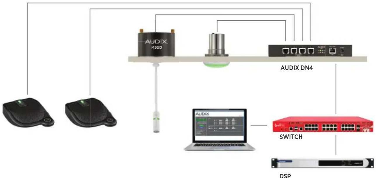
flowchart
graph TD
    A["User Interface"] --> B["AUDIX M55D"]
    A --> C["AUDIX"]
    B --> D["Switch"]
    C --> D
    D --> E["DSP"]
    B --> F["AUDIX DN4"]
    C --> F
    F --> G["User Interface"]
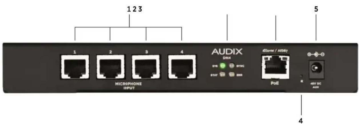
HARDWARE FEATURES
- Ports for Audix RJ45-equipped, single-element microphones
- Status LED indicators
- Ethernet and PoE RJ45 jack
-
Reset button
-
Optional external DC power supply input jack (PSDN4C) (when PoE is not available)
INSTALLATION
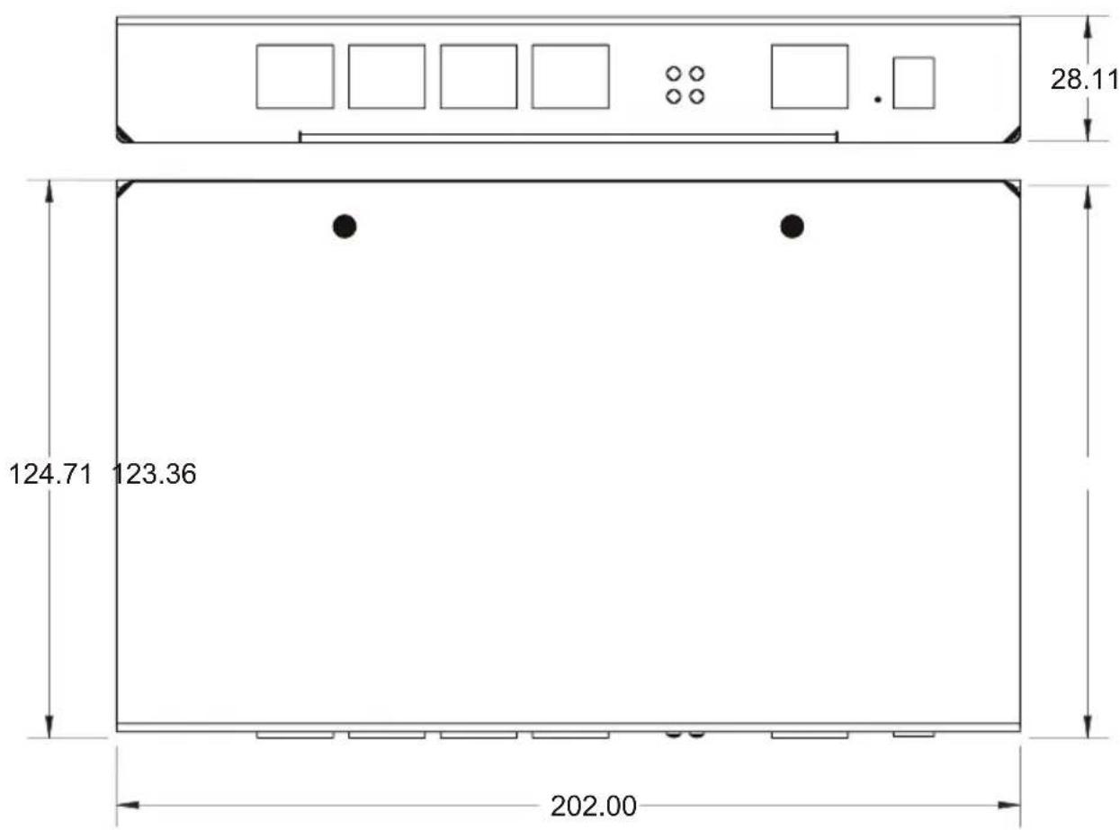
The DN4 is designed to be mounted to a flat wood or metal surface on top or under a table or in the ceiling using the supplied mounting brackets. Install the mounting brackets by aligning the off set holes in the bracket with the threaded holes on the sides of the interface and attach using the supplied screws. Position the interface on the mounting surface and mark the mounting holes. Drill holes in the mounting surface and attach the unit using screws appropriate to the material. Secure seismic cable under any screw.

CONNECTIONS
The DN4 has four RJ45 ports for connecting any Audix RJ45-equipped, single-element microphone, including those with integrated support for LED indicators and contact closures. All ports provide 48V phantom power.
Attach Audix RJ45-equipped microphones to the microphone ports with CAT5, CAT6, or CAT7 cable*. In high RF interference environments, Audix CAT7 shielded cable is recommended. All models of Audix RJ45-equipped microphones have been tested to function with CAT7 cable lengths up to 300 feet between microphone and DN4 interface, allowing for more flexible installation and longer cable runs than other Dante interfaces on the market.
Connect the Ethernet cable to the PoE port of the DN4 and the opposite end to a PoE-enabled port on an appropriate switch, using CAT5, CAT6, or CAT7 cable.
If PoE is not available, a PoE injector may be used or connect the optional 48V external power source (PSDN4C) to the auxiliary power jack on the front of the unit.
LED DESCRIPTIONS
There are four LED indicators on the front of the unit, as shown below.

The SYS, ERR, and SYNC LEDs show the status of the Dante chipset. The STAT LED indicates the state of the hardware and 3rd party control software.
There are two LEDs on the Ethernet / PoE RJ45 port. The left LED is green and will be on when a 100 Mbps Ethernet link is working. The right LED is amber/orange and will flash to indicate data activity.
The reset button performs two different operations. To select one of these operations, use the end of a small paperclip or similar pointed item to hold down the reset button for the number of seconds indicated below, then release.
The Dante chipset can be restarted by quickly pressing and releasing the RESET button. The STAT LED will not change while the RESET button is being pressed. No user settings are cleared during this operation. Note that audio streaming will stop, the device will disappear from the network and reappear a few seconds later.
To reset the device to factory default settings, press and hold the RESET button for longer than 3 seconds. The device settings will be erased and the Dante chipset will enter factory mode (SYS, ERR, and SYNC LEDs are amber). The device may be updated with Audinate's Firmware Update Manager in this mode. To resume normal run mode, reboot the Dante device by quickly pressing and releasing the RESET button, as described before.
Operation STAT LED State
| Reboot Dante into runtime mode | Press and release the reset button quickly, while STAT LED is green. |
 |
Clear device configuration Hold the reset button for longer than 3 seconds. Release when STAT LED changes from green to red.

The settings cleared to default values include, but are not limited to, the following:
- Dante device name
- IP address (dynamic)
- Audio routes
• Pre-amp gains (0 dB)
• High-pass filters (15 Hz) - Low-pass filters (off/bypassed)
- LED outputs (off)
THIRD-PARTY API: NETWORK DEVICE CONTROL
In addition to Dante audio streams, the DN4 microphone interface provides logic and audio controls using the 3rd party API: Network Device Control (NDC). The NDC API provides the following functions:
- Control up to two (2) LEDs or Logic Outputs on each mic port
- Read one (1) Button or Logic Input on each mic port
- Read microphone ID value
Complete API documentation is available in document NDC Protocol & API v1.0.1, available at audixusa/API
SETTING UP AES67 STREAMS
To configure the device to support AES67 streams instead of the Audinate Dante flows, follow Audinate's AES67 configuration guide, available here:
- https://dev.audinate.com/GA/dante-controller/userguide/webhelp/content/aes67_config.htm
Note that other manufacturers supporting AES67 may also provide their own instructions for setting up and using AES67 streams from a compatible Dante device.
UPDATING DANTE FIRMWARE
Audinate periodically updates the firmware for Dante devices and offers a utility for updating devices over the network. Refer to the Dante Firmware Update Manager User Guide for instructions on how to use the Audinate update utility, including how to recover from failsafe mode.
- https://www.audinate.com/content/dante-fi rmware-update-manager-user-guide
Complete instructions and troubleshooting tips are provided in the Audinate Firmware Update Manager User Guide document.
IMPORTANT PRODUCT INFORMATION
The DN4 microphone interface is tested to the UL 2043 standard and includes brackets designed to allow fl exibility in mounting options.
Note: This equipment has been tested and found to comply with the limits for a Class A digital device, pursuant to Part 15 of the FCC Rules and EN55024 / EN55032. These limits are designed to provide reasonable protection against harmful interference when the equipment is operated in a commercial environment. This equipment generates, uses, and can radiate radio frequency energy and, if not installed and used in accordance with the instruction manual, may cause harmful interference to radio communications.

This symbol means the product must not be discarded as household waste, and should be delivered to an appropriate collection facility for recycling. Proper disposal and recycling helps protect natural resources, human health and the environment. For more information on disposal and recycling of this product, contact your local municipality, disposal service, or the business where you bought this product
PRODUCT REGISTRATION:
Please register your product online at AudixUSA.com/register
SERVICE AND WARRANTY:
For service and warranty information, visit AudixUSA.com/service.
APPENDIX A: ADVANCED CONNECTIVITY GUIDE
The Audix Dante | AES67 Integrated Microphone System is designed to eliminate the need to fabricate RJ45 microphone connections. If custom connections are desired, use the diagrams below.
The LED (Logic Out) output lines provide 5V outputs and can drive up to 10 mA of current, enough to power LEDs directly without additional circuitry. The LED signal is controllable with the 3rd party API (see previous page).
The Button (Logic In) input line operates on 3.3V and provides an internal pull-up. This means a contact closure should be connected across the BUTTON and DGND pins without any additional circuitry. Do not attempt to drive voltage into the BUTTON pin. Only use open-drain drive circuitry. The logic input signals from all microphone ports are read with the 3rd party API (see Section 6).
The audio input lines are balanced, differential inputs. Industry-standard 48V phantom power is always available on these lines.

Single-element RJ45 microphone port
- OVERVIEW
- IN THE BOX
- OPTIONAL ACCESSORIES
- HARDWARE FEATURES
- INSTALLATION
- CONNECTIONS
- LED DESCRIPTIONS
- THIRD-PARTY API: NETWORK DEVICE CONTROL
- SETTING UP AES67 STREAMS
- UPDATING DANTE FIRMWARE
- IMPORTANT PRODUCT INFORMATION
- PRODUCT REGISTRATION:
- SERVICE AND WARRANTY:
- APPENDIX A: ADVANCED CONNECTIVITY GUIDE
Brand : Audix
Model : DN4
Category : Microphone