
DM-NAX-4ZSA-50 - Professional audio equipment Crestron - Free user manual and instructions
Find the device manual for free DM-NAX-4ZSA-50 Crestron in PDF.


| Product Type | Network Audio Amplifier |
| Model | DM-NAX-4ZSA-50 |
| Brand | Crestron |
| Number of Zones | 4 |
| Amplifier Output Power | 50 Watts per channel (4Ω) |
| Audio Input | Dante / AES67 digital audio |
| Audio Output | 4-channel amplified speaker output |
| Dimensions (H x W x D) | 1.7 x 8.9 x 6.6 in (43 x 226 x 168 mm) |
| Weight | 1.5 lb (0.68 kg) |
| Power Supply | PoE+ (IEEE 802.3at) or 24VDC external |
| Power Consumption | 30W typical |
| Cooling | Fanless, passive cooling |
| Mounting | Rack mountable (1U half-rack) |
| Network Connectivity | 1 Gigabit Ethernet with PoE+ |
| Control | Crestron control system, Web UI, API |
| Audio Processing | EQ, crossover, delay, volume, mute |
| Operating Temperature | 32°F to 104°F (0°C to 40°C) |
| Maintenance | Clean with dry, lint-free cloth; avoid liquids |
| Safety | Do not block vents; use in well-ventilated area |
| Spare Parts & Repairability | Contact Crestron authorized service |
Frequently Asked Questions - DM-NAX-4ZSA-50 Crestron
User questions about DM-NAX-4ZSA-50 Crestron
0 question about this device. Answer the ones you know or ask your own.
Ask a new question about this device
Download the instructions for your Professional audio equipment in PDF format for free! Find your manual DM-NAX-4ZSA-50 - Crestron and take your electronic device back in hand. On this page are published all the documents necessary for the use of your device. DM-NAX-4ZSA-50 by Crestron.
USER MANUAL DM-NAX-4ZSA-50 Crestron
Audio-over-IP Distribution Platform
Original Instructions
The U.S. English version of this document is the original instructions. All other languages are a translation of the original instructions.
Regulatory Model: M1845004
Crestron product development software is licensed to Crestron dealers and Crestron Service Providers (CSPs) under a limited nonexclusive, nontransferable Software Development Tools License Agreement. Crestron product operating system software is licensed to Crestron dealers, CSPs, and end-users under a separate End-User License Agreement. Both of these Agreements can be found on the Crestron website at www.crestron.com/legal/software_license_agreement.
The product warranty can be found at www.crestron.com/warranty.
The specific patents that cover Crestron products are listed at www.crestron.com/legal/patents.
Certain Crestron products contain open source software. For specific information, visit www.crestron.com/opensource.
Crestron, the Crestron logo, Crestron Toolbox, DM, DM NAX, DM NVX and XiO Cloud are either trademarks or registered trademarks of Crestron Electronics, Inc. in the United States and/or other countries. Apple, AirPlay, and macOS are either trademarks or registered trademarks of Apple Inc., registered in the U.S. and other countries. Bluetooth is either a trademark or registered trademark of Bluetooth SIG, Inc. in the United States and/or other countries. Dante is either a trademark or registered trademark of Audinate Pty Ltd. in the United States and/or other countries. Deezer is either a trademark or registered trademark of Deezer société anonyme (sa) in the United States and/or other countries. SOUNDMACHINE is either a trademark or registered trademark of Easy Tempo, Inc. in the United States and/or other countries. RACO is either a trademark or registered trademark of Hubbell Incorporated in the United States and/or other countries. Active Directory and Windows are either trademarks or registered trademarks of Microsoft Corporation in the United States and/or other countries. Pandora is either a trademark or registered trademark of Pandora Media, Inc. in the United States and/or other countries. Roon and Roon Core are either trademarks or registered trademarks of Roon Labs LLC in the United States and/or other countries. SiriusXM is either a trademark or registered trademark of Sirius XM Radio Inc. in the United States and/or other countries. Spotify is either a trademark or registered trademark of Spotify Inc. in the United States and/or other countries. TIDAL is either a trademark or registered trademark of Tidal Music as Corporation Norway in the United States and/or other countries. TOSLINK is either a trademark or registered trademark of Toshiba Electronics Devices & Storage Corporation in the United States and/or other countries. USB-C is either a trademark or registered trademark of USB Implementers Forum, Inc. in the United States and/or other countries. Qobuz is either a trademark or registered trademark of Xandrie société anonyme (sa) in the United States and/or other countries. Other trademarks, registered trademarks, and trade names may be used in this document to refer to either the entities claiming the marks and names or their products. Crestron disclaims any proprietary interest in the marks and names of others. Crestron is not responsible for errors in typography or photography.
©2024 Crestron Electronics, Inc.
Contents
Overview .1
Features .1.
Products .1
DM-NAX-2XLRI-1G 2
DM-NAX-8ZSA 4
Physical Description.4
Applications 8
DM-NAX-16AIN 15
Physical Description 15
Application .18.
DM-NAX-4ZSA-50 19
DM-NAX-4ZSP 21
Physical Description.21
DM-NAX-AMP-X300 .25
DM-NAX-AUD-IO .27.
DM-NAX-AUD-USB 28
DM-NAX-BTIO-1G 30
Specifications
DM-NAX-2XLRI-1G Specifications 32
Specifications 32
Dimension Drawing 35
DM-NAX-8ZSA Specifications 36
Specifications 36
Dimension Drawing 39
DM-NAX-4ZSA-50 Specifications 40
Specifications 40
Dimension Drawing 43
DM-NAX-4ZSP Specifications 44
Specifications 44
Dimension Drawing 47
DM-NAX-16AIN Specifications 48
Specifications 48
Dimension Drawing 50
DM-NAX-AMP-X300 Specifications 51
Specifications 51
Dimension Drawings 54
DM-NAX-AUD-IO Specifications 55
Specifications 55
Dimension Drawing 57
DM-NAX-AUD-USB Specifications 58
Specifications 58
Dimension Drawing 60
DM-NAX-BTIO-1G Specifications 61
Specifications 61
Dimension Drawing 63
Installation .64
DM-NAX-2XLRI-1G Installation 65
In the Box 65
Mounting the Device 65
Connect the Device 68
Reset the Device 69
DM-NAX-8ZSA Installation 71
In the Box.71
Install the Device 72
Connect the Device 73
Apple® AirPlay® Setup 77
Spotify® Connect Setup 78
Observe the LED Indicators 78
Reset the Device 80
DM-NAX-4ZSA-50 Installation 81
In the Box 81
Install the Device 82
Connect the Device 85
Speaker Connections 87
Spotify® Setup 87
Observe the LED Indicators 88
Reset the Device 88
DM-NAX-4ZSP Installation 90
In the Box....90
Install the Device....91
Connect the Device 92......
Apple® AirPlay® Setup 94
Spotify® Connect Setup 95
Observe the LED Indicators 96
Reset the Device 97
DM-NAX-16AIN Installation 98
In the Box 98
Install the Device 99
Connect the Device 101
Observe the LED Indicators 103
Reset the Device 104
DM-NAX-AMP-X300 Installation 105
In the Box 106
Install the Device 107
Connect the Device 111
Speaker Mode Selection Switch 111
Lo-Z Modes Selection Switch 112
Observe the LED Indicators 112
Reset the Device.113
Output Wiring Options 114
DM-NAX-AUD-IO Installation 117
In the Box 117
Mount the Device.117
Connect the Device 121
Reset the Device 123
DM-NAX-AUD-USB Installation 125
In the Box 125
Mount the Device 125
Connect the Device.129
Reset the Device 131
DM-NAX-BTIO-1G Installation 132
In the Box 132
Mount the Device 132
Connect the Device 134
Reset the Device 135
Configuration 136
DM-NAX-2XLRI-1G 137
Web Interface Configuration 137
Action 139
Status 143
Settings 145
Security 177
802.1x Configuration 186
Access the Web Interface With the Crestron Toolbox™ Application.... 188
DM-NAX-8ZSA 189
Web Interface Configuration 189
Action 192
Status 201
Settings 204
Security 244
802.1x Configuration 253
Access the Web Interface With the Crestron Toolbox™ Application 255
DM-NAX-4ZSA-50 256
Web Interface Configuration 256
Action 258
Status 265
Settings 267
Security 302
802.1x Configuration 311
Access the Web Interface With the Crestron Toolbox™ Application 313
DM-NAX-4ZSP 314
Web Interface Configuration.314
Action 317
Status 325
Settings 328
Security 363
802.1x Configuration .372
Access the Web Interface With the Crestron Toolbox™ Application.374
DM-NAX-16AIN 375
Web Interface Configuration..375
Action 378
Status 384
Settings 387
Security 395
802.1x Configuration 404
Access the Web Interface With the Crestron Toolbox™ Application.406
DM-NAX-AMP-X300 407
Web Interface Configuration..407
Action 409
Status 413
Settings 417
Security 463
802.1x Configuration 471
Access the Web Interface With the Crestron Toolbox™ Application.472
DM-NAX-AUD-IO 473
Web Interface Configuration 473
Action 475
Status 479
Settings 481
Security 517
802.1x Configuration 526
Access the Web Interface With the Crestron Toolbox™ Application 528
DM-NAX-AUD-USB 529
Web Interface Configuration 529
Action 531
Status 535
Settings 537
Security 573
802.1x Configuration 582
Access the Web Interface With the Crestron Toolbox™ Application 584
DM-NAX-BTIO-1G 585
Web Interface Configuration 585
Action 587
Status 591
Settings 593
Security 629
802.1x Configuration .638
Access the Web Interface With the Crestron Toolbox™ Application..640.
Resources 641
Crestron Support and Training.641
Programmer and Developer Resources.641
Product Certificates..641
Overview
DM NAX® Audio-over-IP (AoIP) solutions are built on AES67 standards with the additional ease of configuration via a web interface, SIMPL, C#, and/or a RESTful API. It is compatible with DM NVX® endpoints through an AES67 secondary audio stream, and also with third-party AES67 solutions, including Dante® devices.
Features
- Scalability: DM NAX systems can scale to meet any demand. DM NAX supports up to 32 DM NAX devices in sync. In addition, DM NAX can support any combination of units for additional input-output requirements.
- Flexibility: Multiple input-output options are supported. Built-in streaming services and an expanding hardware lineup are available for a broad range of applications.
- Interoperability: DM NAX is built on AES67 AoIP standards and is compatible with any third-party AES67 solution
Products
The following products are described in this product manual:
• DM-NAX-2XLRI-1G on page 2
• DM-NAX-8ZSA on page 4
• DM-NAX-16AIN on page 15
• DM-NAX-4ZSA-50 on page 19
• DM-NAX-4ZSP on page 21
• DM-NAX-AMP-X300 on page 25
• DM-NAX-AUD-IO on page 27
• DM-NAX-AUD-USB on page 28
• DM-NAX-BTIO-1G on page 30
DM-NAX-2XLRI-1G
The DM-NAX-2XLRI-1G provides a single-gang wall mount for (2) XLR inputs. The rear of the wall plate features an Ethernet connection for power and DM NAX® audio-over-IP (AOIP) networking. The rear panel also features a five-pin line-level audio output for transmitting an audio signal to a Crestron media wall plate (MP-WP-2XLRO-1G and MP-WP-2RCAO-1G).

- Two XLR input connectors
- Two rear-panel line-level audio outputs
- Single-gang U.S. wall box installation
• Power over Ethernet (PoE) network powered
- Mountable in a standard US electrical box or on a rack rail via included hardware
- Connects directly to a managed network to route to or from other DM NAX® and DM NVX® devices
- Interoperable with Dante® audio networking devices via AES67 compatibility
- Streamlined configuration through a web interface
- Seamless Crestron system integration with SIMPL Windows programming
Audio-over-IP
DM NAX takes audio distribution to a whole new level by putting it on the network. The DM-NAX-2XLRI-1G sends and receives DM NAX and AES67 encoded audio over a standard IP network. A single DM NAX system can handle audio distribution between 32 DM NAX devices and supports up to 256 audio output zones. DM NAX devices can seamlessly pull and distribute the audio from DM NVX sources.
Line Level and Microphone Level Support
The front panel XLR connectors of the DM-NAX-2XLRI-1G can be configured for either line level or microphone level input. Each XLR input can be configured to send a +48V phantom power signal to power a connected condenser microphone.
Digital Signal Processing (DSP)
DSP capabilities such as a 5-band EQ per XLR input and level control of all input and output signal typ are available to configure via the web user interface.
Encoder and Decoder Functionality
The DM-NAX-2XLRI-1G can operate as a network AV encoder and decoder. The local input sources on one amplifier can be sent as AoIP streams to DM NAX, Dante, or AES67 capable devices.
Simultaneously, the DM-NAX-2XLRI-1G can receive AoIP streams from these same devices and decode them for local output.
DM-NAX-8ZSA
The Crestron DM-NAX-8ZSA is a next generation DM NAX® Audio-over-IP (AoIP) amplifier that puts Crestron multiroom audio distribution on the network. It provides eight amplified stereo zone (16-channel) outputs. Four stereo line-level outputs mirror speaker zone outputs 1-4.
A dedicated streaming service player for each of the eight zones enables complete freedom to stream different content in every zone. Full DSP capabilities are available on the line and speaker outputs.
Voltage triggers corresponding to the 4 stereo line-level analog outputs can be used to power connected external amplifiers on and off.
The DM-NAX-8ZSA supports Amazon Connected Speakers.
For installation information, refer to the DM-NAX-8ZSA Quick Start.
Physical Description
The following sections provide information about the connectors, controls, and indicators that are available on the DM-NAX-8ZSA device.
Front Panel
The following illustration shows the front panel of the DM-NAX-8ZSA.

1 PWR: (1) LED, indicates operating power is supplied; illuminates amber while booting, white when powered on, red when in standby (no audio or LAN connection), and off when no power is supplied.
2 LAN: (1) LED, illuminates white when the amplifier is connected to a network with a valid IP address, and off when the device is not connected to a network or the IP address is invalid.
3 NAX: (1) LED, illuminates white when the AoIP is ready to pass and the unit's PTP clock is synced, and off when there is no AoIP is passing to or from an amplifier and/or PTP is not synced.
4 SOURCE: (8) LEDs, illuminates white when a signal is detected on the specified input/source, red when there is clipping on an analog input or bitstream audio detected on a digital input, and off when there is no signal detected on the specified input/source.
5 ZONE: (8) LEDs, illuminates white when there is audio output on the indicated zone, red when clipping or a fault is detected on the zone output due to overcurrent, over temperature, or low voltage.
Rear Panel
The following illustration shows the rear panel of the DM-NAX-8ZSA.

1 DIGITAL INPUTS: (2) JIS F05 female TOSLINK® optical fiber connectors, S/PDIF optical digital audio inputs;
(2) RCA female; S/PDIF coaxial digital audio inputs; Input Impedance: 75 Ω
2 ANALOG INPUTS: (8) RCA female comprising (4) unbalanced stereo line-level audio inputs; Input Impedance: 10000 Ω;
Maximum Input Level: 2 Vrms
3 SPEAKER OUTPUTS: (16) 2-pin 7.62 mm detachable terminal block;
Balanced/unbalanced stereo line-level audio outputs,
Output Impedance: 4 Ω/8 Ω;
Maximum Output Level: 150 W single-ended at 8 Ω, 300 W single-ended at 4 Ω, with zones bridgeable up to 500 W at 8 Ω.
4 LINE OUTPUTS: (8) RCA connectors, female; Comprise (4) unbalanced line-level stereo audio outputs (mirror corresponding speaker outputs pair 1 - 4);
Output Impedance: 100 Ω; Maximum Output Level: 2 Vrms;
(2) 5-pin 3.5mm detachable terminal blocks; Balanced stereo line-level audio outputs (mirror corresponding unbalanced RCA output pairs 1 - 2);
Output Impedance: 150 Ω; Maximum Output Level: 4 Vrms
5 I/O Port: (1) single 5-pin Phoenix block that comprises four I/O ports, and a shared ground
6 TRIGGER: (2) 4-pin Phoenix connectors for all outputs;
The triggers correspond to the respective LINE OUTPUTS 1-4 and will send a +10V signal to an external amplifier whenever an audio signal is routed to the respective line output.
7 Ethernet 1: (1) 8-pin RJ-45 connector, female;
100BASE-TX/1000BASE-T Ethernet port;
Green LED indicates Ethernet link status;
Flashing amber LED indicates Ethernet activity
Ethernet 2: (1) 8-pin RJ-45 connector, female;
100BASE-TX/1000BASE-T Ethernet port;
Green LED indicates Ethernet link status;
Flashing amber LED indicates Ethernet activity
8 SETUP: (1) Push button: Pressing and holding the SETUP button for 15 seconds with power supplied clears network settings and restores the default DHCP mode;
Pressing and holding the SETUP button with power disconnected, then connecting the power supply and continuing to hold SETUP button for 30 seconds performs a factory restore;
(1) LED, illuminates red when the button is pressed, flashes red when reset has been initiated
9 CONSOLE: (1) Standard USB 2.0 Type B connector, female
10 GROUND: 6-32 screw, chassis ground lug
10A Fuse: 10 A Fuse
12 POWER OUTLET: (1) 100-240V\~50/60Hz Universal AC; IEC 60320 C14 Main power inlet, mates with removable power cord (included)
Applications
This section shows DM-NAX-8ZSA device in multizone applications.

flowchart
graph TD
    A["Display"] --> B["Sound System"]
    B --> C["Living Room"]
    C --> D["AVR"]
    D --> E["DM-NAX-8ZSA"]
    E --> F["Audio Sources¹"]
    F --> G["LAN"]
    G --> H["Display"]
    H --> I["Up to 4 more zones"]
    I --> J["Playroom"]
    J --> K["Master Bed"]
    K --> L["Powder Room (mirrors AVR)"]
    E --> M["Video Sources"]
    M --> N["Line Level Audio"]
    N --> O["HDMI°"]
    O --> P["Speaker Level Audio"]
    P --> Q["Line Level Audio"]
    Q --> R["Ethernet"]
    R --> S["Video Sources"]
    S --> T["DM NVX Chassis"]
    T --> U["LAN"]
NOTES:
- DM NAX devices generate multicast traffic on the network. Even a single DM NAX device connected to an unmanaged network can cause communication issues with other devices connected to the same network. For information on system installation, refer to the DM NAX® Audio-over-IP System Design Guide.
- If DM NAX devices must be set up before configuring network settings on a managed switch, use the Port Selection on page 242 functionality on the DM NAX device to isolate the AoIP traffic to the secondary Ethernet port. For example, when connecting the DM NAX to a control system or authenticating streaming service accounts. This ensures that during setup, the primary Management port of the device does not receive AoIP traffic.
This application diagram shows the following setup:
- Up to eight zones of amplification and audio distribution
- Local line level input
- Local line level output to an Audio Video Receiver (AVR) mirroring a zone of amplification
• Available DM NVX audio streams to route audio from video sources to non-video zones
• Available music streaming services on up to eight DM NAX zones

flowchart
graph TD
    A["Sound System"] -->|Display| B["Video Sources"]
    B --> C["DM-RMC"]
    C --> D["AVR"]
    D --> E["DM-NAX-8ZSA"]
    E --> F["Audio Sources¹"]
    F --> G["LAN"]
    G --> H["Display"]
    H --> I["Up to 4 more zones"]
    I --> J["DM-RMC Playroom"]
    J --> K["Master Bed"]
    K --> L["Powder Room (mirrors AVR)"]
    L --> M["Kitchen"]
    M --> N["Speaker Level Audio"]
    N --> O["Line Level Audio"]
    O --> P["Ethernet"]
    P --> Q["DM"]
    Q --> R["DM-NAX-16AIN"]
    R --> S["Video Sources"]
    S --> T["DM® Chassis"]
    T --> U["LAN"]
    U --> V["Display"]
    V --> W["Up to 4 more zones"]
    W --> X["Speaker Level Audio"]
    X --> Y["HDMI®"]
    Y --> Z["Line Level Audio"]
    Z --> AA["Ethernet"]
    AA --> AB["DM"]
This application diagram shows the following setup:
- Up to eight zones of amplification and audio distribution
- Local line level input
- Local line level output to an AVR mirroring a zone of amplification
• Available music streaming services on up to eight DM NAX zones - The DM-NAX-16AIN is used to transmit audio from the DM chassis' video sources onto the DM NAX network for routing to the non-video zones on the DM-NAX-8ZSA

flowchart
graph TD
    A["LAN"] --> B["DM-NAX-8ZSA"]
    C["2.1 Using Line Output to Active Subwoofer"] --> B
    D["2.1 Using Bridged Sub Output to Passive Subwoofer"] --> B
    E["2.1 Using Bridged Outputs to L,R, and Passive Subwoofer"] --> B
    B --> F["Ethernet"]
    B --> G["Line Level Audio"]
    B --> H["Speaker Level Audio"]
This application diagram shows different 2.1 configurations and how they affect the zone count of an DM-NAX-8ZSA. By default, a zone comprises two speaker outputs (a left and a right).
- The 2.1 configuration at the left of the diagram comprises two speaker outputs, with an additional line output that feeds the subwoofer.
NOTE: This configuration is only applicable for zones with an available line output (1 through 4).
- The middle configuration (2.1 bridged sub) comprises four speaker outputs - two left and right and two for the bridged sub.
NOTE: This configuration is only applicable when enough subsequently numbered zones are available on the amplifier. For example, the 2.1 bridged sub cannot be used on zone 8 as there is no speaker output pair 9.
- The right configuration (bridged 2.1) comprises six speaker outputs - two for the bridged left, two for the bridged right, and two for the bridged sub.
NOTE: This configuration is only applicable when enough subsequently numbered zones are available on the amplifier. For example, the 2.1 bridged sub cannot be used on zone 7 or 8 as there is no speaker output pair 9 or 10.
Having higher output-count zone configurations on a single DM-NAX-8ZSA will affect the total available zone count on a given box. For example, if you have a single bridged 2.1 configuration on an DM-NAX-8ZSA, it will lower the maximum zone count to six, as the bridged 2.1 consumes three zones worth of speaker outputs on its own.

flowchart
graph TD
    subgraph_Zone1_1["Zone 1 - Men's Locker Room"]
        A["AMP-4600"] --> B["Line Level Audio"]
        C["AMP-X300"] --> D["Speaker Level Audio"]
    end

    subgraph_Zone2_1["Zone 2 - Women's Locker Room"]
        E["AMP-X300"] --> F["Line Level Audio"]
        G["AMP-X300"] --> H["Speaker Level Audio"]
    end

    subgraph_Zone3_1["Zone 3 - Lobby"]
        I["AMP-4600"] --> J["Line Level Audio"]
        K["AMP-X300"] --> L["Speaker Level Audio"]
    end

    subgraph_Zone4_1["Zone 4 - Break Room"]
        M["AMP-X300"] --> N["Line Level Audio"]
        O["AMP-X300"] --> P["Speaker Level Audio"]
    end

    Q["DM-NAX-8ZSA"] --> R["LAN"]
    Q --> S["Left"]
    Q --> T["Right"]

    U["(Signal is shared within zone)"]
    V["(Signal is shared within zone)"]
    W["(Signal is shared within zone)"]
This application diagram shows the following setup:
- Mirrored zones (Zone 1 and Zone 2 each have two rooms receiving the same audio signal)
- Parallel wiring of low impedance speakers in two Locker Room areas
NOTE: This is a parallel wiring of 8 Ω speakers for a total supported load of 4 Ω per channel. Parallel wiring lowers the effective impedance of the connected loads, so make sure the speakers impedance matches the supported impedance levels from the DM-NAX-8ZSA.
- Using the line outputs of the DM-NAX-8ZSA to feed high-impedance amplifiers (AMP-X300s and AMP-4600) for long speaker runs
- Bussing to multiple zones to feed a large group of low-impedance speakers with the same signal and shared controls

flowchart
graph TD
    LAN["LAN"] --> DM_NAX_8ZSA["DM-NAX-8ZSA"]
    DM_NAX_8ZSA <--> DM_NAX_8ZSA2["..."]
    DM_NAX_8ZSA2 <--> AMP_X300["AMP-X300"]
    Room1["Room 1"] --> DM_NAX_8ZSA
    Room2["Room 2"] --> DM_NAX_8ZSA
    Room3["Room 3"] --> DM_NAX_8ZSA
    Room4["Room 4"] --> DM_NAX_8ZSA
    DM_NAX_8ZSA <--> DM_NAX_8ZSA3["..."]
    DM_NAX_8ZSA3 <--> AMP_X300
    AMP_X300 --> Lobby["Lobby"]
    AMP_X300 --> Pool["Pool"]
    HighImpedanceSpeakers["High Impedance Speakers"]
    AdditionalRooms["Additional Rooms"]
    Ethernet["Ethernet"]
    LineLevelAudio["Line Level Audio"]
    SpeakerLevelAudio["Speaker Level Audio"]
This application diagram shows a commercial setup using casting service streaming applications. For example, in a hotel, each room can receive a cast from a third-party device. The Lobby and Pool zones can exist on another DM-NAX-8ZSA unit that is on the same LAN or on a separate VLAN or WAP to c to/control those zones.
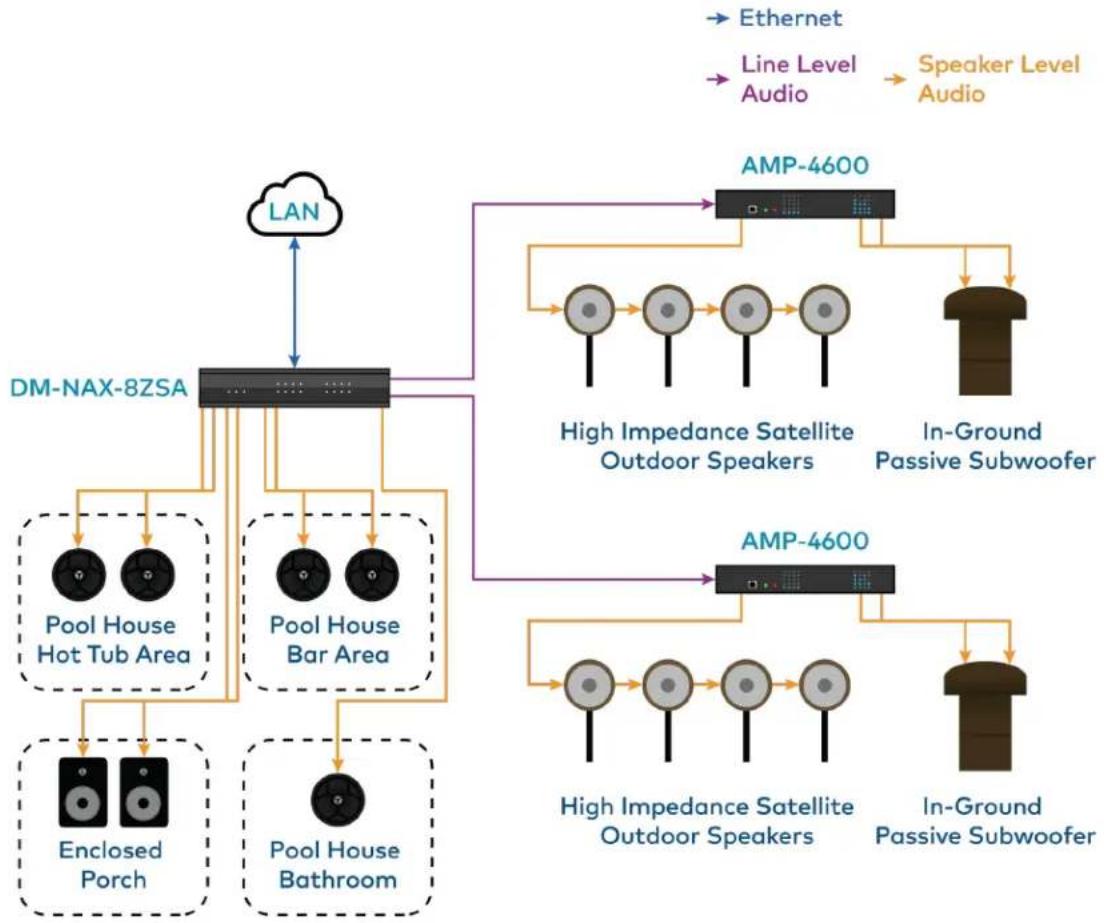
flowchart
graph TD
    A["LAN"] --> B["DM-NAX-8ZSA"]
    B --> C["Pool House Hot Tub Area"]
    B --> D["Pool House Bar Area"]
    B --> E["Enclosed Porch"]
    B --> F["Pool House Bathroom"]
    C --> G["AMP-4600"]
    D --> G
    E --> G
    F --> G
    G --> H["High Impedance Satellite Outdoor Speakers"]
    G --> I["In-Ground Passive Subwoofer"]
    G --> J["High Impedance Satellite Outdoor Speakers"]
    G --> K["In-Ground Passive Subwoofer"]
    L["Ethernet"] --> B
    M["Line Level Audio"] --> B
    N["Speaker Level Audio"] --> B
This application diagram shows zones using only the line outputs. Line outputs 1 and 2 feed high impedance amplifiers driving speakers for large outdoor spaces and speaker zone outputs 5-8 feed low-impedance indoor spaces without overlap of signals. The LAN cloud shows that any individual applications can exist as part of a large DM NAX system.
DM-NAX-16AIN
The Crestron DM NAX® Audio-over-IP (AoIP) encoder (DM-NAX-16AIN) provides 16 local stereo audio inputs to a DM NAX Crestron multiroom audio distribution network. It provides 8 digital inputs comprised of 4 SPDIF TOSLINK® connectors and 4 SPDIF coaxial connectors. Each digital input supports 2-channel PCM audio. The DM-NAX-16AIN also provides 8 analog stereo inputs. Inputs 1-4 offer balanced 5-pin terminal block connectors in parallel with unbalanced RCA connectors, and inputs 5-8 offer RCA connectors.
For installation information, refer to the DM-NAX-16AIN Quick Start.
Physical Description
The following sections provide information about the connectors, controls, and indicators that are available on the DM-NAX-16AIN device.
Front Panel
The following illustration shows the front panel of the DM-NAX-16AIN.

1 PWR: (1) LED, indicates operating power is supplied; illuminates amber while booting, white when powered on, red when in standby (no audio or LAN connection), and off when no power is supplied.
2 LAN: (1) LED, illuminates white when the device is connected to a network with a valid IP address, and off when the device is not connected to a network or the IP address is invalid.
3 NAX: (1) LED, illuminates white when the AoIP is ready to pass and the unit's PTP clock is synced, and off when there is no AoIP is passing to or from the device and/or PTP is not synced.
4 ANALOG SOURCE: (8) LEDs, illuminates white when a signal is detected on the specified input/source, red when there is clipping on an analog input and off when there is no signal detected on the specified input/source.
5 DIGITAL SOURCE: (8) LEDs, illuminates white when a signal is detected on the specified input/source, red when there is bitstream audio detected on a digital input, and off when there is no signal detected on the specified input/source.
Rear Panel
The following illustration shows the rear panel of the DM-NAX-16AIN.
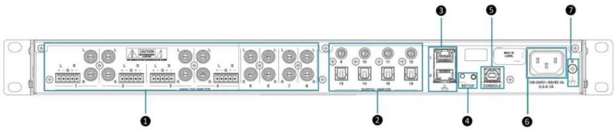
1 ANALOG INPUTS: (8) RCA female comprising (4) unbalanced stereo line-level audio inputs;
(4) 5-pin phoenix balanced connector;
Input Impedance: 10000 Ω;
Maximum Input Level: 2 Vrms
2 DIGITAL INPUTS: (4) JIS F05 female TOSLINK® optical fiber connectors, S/PDIF optical digital audio inputs;
(4) RCA female; S/PDIF coaxial digital audio inputs;
Input Impedance: 75 Ω
3 Ethernet 1: (1) 8-pin RJ-45 connector, female;
100BASE-TX/1000BASE-T Ethernet port;
Green LED indicates Ethernet link status;
Flashing amber LED indicates Ethernet activity
Ethernet 2: (1) 8-pin RJ-45 connector, female;
100BASE-TX/1000BASE-T Ethernet port;
Green LED indicates Ethernet link status;
Flashing amber LED indicates Ethernet activity
4 SETUP: (1) Push button: Pressing and holding the SETUP button for 15 seconds
with power supplied clears network settings and restores the default DHCP mode;
Pressing and holding the SETUP button with power disconnected, then connecting the power supply and continuing to hold SETUP button for 30 seconds performs a factory restore;
(1) LED, illuminates red when the button is pressed, flashes red when reset has been initiated
5 CONSOLE: (1) Standard USB 2.0 Type B connector, female
6 POWER INLET: (1) 100-240V\~50/60Hz Universal AC; IEC 60320 C14 Main power
inlet, mates with removable power cord (included)
7
GROUND: 6-32 screw, chassis ground lug
Application
This section shows DM-NAX-16AIN device in a multizone application.

flowchart
graph TD
    A["Sound System"] -->|Display| B["Video Sources"]
    B --> C["DM-RMC"]
    C --> D["AVR"]
    D --> E["DM-NAX-8ZSA"]
    E --> F["Audio Sources¹"]
    F --> G["LAN"]
    G --> H["DM-NAX-16AIN"]
    H --> I["DM® Chassis"]
    I --> J["Ethernet"]
    I --> K["HDMI""]
    I --> L["Line Level Audio"]
    I --> M["Speaker Level Audio"]
    I --> N["DM"]
    E --> O["Powder Room (mirrors AVR)"]
    E --> P["Master Bed"]
    E --> Q["Kitchen"]
    E --> R["Display"]
    E --> S["Up to 4 more zones"]
    E --> T["DM-RMC Playroom"]
    style A fill:#f9f,stroke:#333
    style B fill:#ccf,stroke:#333
    style C fill:#cfc,stroke:#333
    style D fill:#fcc,stroke:#333
    style E fill:#cff,stroke:#333
    style F fill:#ffc,stroke:#333
    style G fill:#fcf,stroke:#333
    style H fill:#cff,stroke:#333
    style I fill:#ffc,stroke:#333
    style J fill:#cfc,stroke:#333
    style K fill:#cfc,stroke:#333
    style L fill:#cfc,stroke:#333
    style M fill:#cfc,stroke:#333
    style N fill:#cfc,stroke:#333
    style O fill:#cfc,stroke:#333
    style P fill:#cfc,stroke:#333
    style Q fill:#cfc,stroke:#333
    style R fill:#cfc,stroke:#333
    style S fill:#cfc,stroke:#333
This application diagram shows the following setup:
- Up to eight zones of amplification and audio distribution
- Local line level input
- Local line level output to an AVR mirroring a zone of amplification
• Available music streaming services on up to eight DM NAX zones - The DM-NAX-16AIN is used to transmit audio from the DM chassis' video sources onto the DM NAX network for routing to the non-video zones on the DM-NAX-8ZSA
DM-NAX-4ZSA-50
The Crestron DM-NAX-4ZSA-50 is a next generation DM NAX® Audio-over-IP (AoIP) amplifier that puts Crestron multiroom audio distribution on the network. It provides four amplified stereo zone (8-channel) outputs and an independent line level zone (2-channel) output.
A dedicated streaming service player for each of the four zones enables complete freedom to stream different content in every zone. Full DSP capabilities are available on the speaker outputs.

natural_image
Front view of a black CRESTRON industrial device labeled DM-NAX-4ZSA-50, showing ports and indicator lights (no readable text beyond labels)• Audio-over-IP (AoIP) amplifier
• Built-in streaming services support
• Full DSP capabilities
• Gallium Nitride (GaN) Class D amplification
- 50 W of output power per channel
- Provides four amplified output zones and one additional line-level output zone
• 1 RU high, half-rack width modular form factor
- Interoperable with Dante® audio networking devices via AES67 compatibility
• Built-in chime support
- Streamlined configuration through a web interface
- Seamless Crestron system integration with SIMPL Windows programming
The DM-NAX-4ZSA-50 supports Amazon Connected Speakers.
Audio-over-IP
The DM-NAX-4ZSA-50 sends and receives DM NAX and AES67 encoded audio over a standard IP network. A single DM NAX system can handle audio distribution between 32 DM NAX devices and supports up to 256 audio output zones. DM NAX devices can seamlessly pull and distribute the audio from DM NVX sources.
Streaming and Casting Services
A dedicated streaming service player is built-in for each zone, supporting AirPlay ^® 2, Internet Radio, Spotify Connect ^™ , Pandora ^® , SiriusXM ^® , TIDAL ^™ , Deezer ^® , Qobuz ^® , Podcasts and more. The DM-NAX-4ZSA-50 delivers streaming, routing, distribution, and amplification in a single device. Streams can be routed to other non-streaming AoIP devices.
Chimes
A library of chimes is built into the unit. Chimes can be assigned to different zones to help identify their Whenever a chime is triggered, the zone audio will duck or pause, so the chime can be clearly heard over active media until the chime concludes.
Digital Signal Processing (DSP)
DSP capabilities such as bass and treble boost and cut, loudness, adjustable delay, speaker protection and limiting, tone profiles, a full 10-band EQ per output, and an option to have line output as a fixed variable level with or without DSP applied are available. Speaker profiles for first and third party speaker models are built in to simplify output DSP tuning.
Encoder and Decoder Functionality
The DM-NAX-4ZSA-50 can operate as a network AoIP encoder and decoder. The local input sources on one amplifier can be sent as AoIP streams to DM NAX, Dante, or AES67 capable devices.
Simultaneously, the DM-NAX-4ZSA-50 can receive AoIP streams from these same devices and decode them for local output.
Modular Design
The DM-NAX-4ZSA-50 is housed in a half-width rack-mountable form factor that can be installed individually or ganged together in a single rack space. The amplifier is high-density stackable with other Crestron DM NAX or X-Series amplifiers, allowing multiple units to be installed vertically in an equipment rack without needing extra ventilation space. Rack mount parts are included, so no additional mounting accessories or rack shelves are required.
Whether mounting in a rack or placing on a shelf, it is easy to combine two amplifiers into a single, full rack-width assembly.
Gallium Nitride (GaN) Amplification
The DM-NAX-4ZSA-50 is the first Crestron amplifier to feature GaN Class D technology. GaN amplification allows higher output power to fit into small form factors without sacrificing efficiency or audio performance. The DM-NAX-4ZSA-50 is capable of 50 W per channel of amplifier output power in a half-width 1RU housing that matches the depth of the DM-NAX-AMP-X300.
DM-NAX-4ZSP
The Crestron DM-NAX-4ZSP is a next generation Audio-over-IP (AoIP) preamplifier that puts Crestron multiroom audio distribution on the network. It provides four stereo zone (8-channel) line-level outputs. A dedicated streaming service player enables streaming different content in each of the four zones.
The DM NAX ^® platform is built on AES67 standards with additional ease of configuration via a web interface, SIMPL Windows, C#, and/or a RESTful API. It is compatible with the following:
- DM NVX® platform through the AES67 secondary audio stream
• Third-party AES67 solutions - Dante® devices via the compatibility mode enabled through Dante Controller
Full DSP capabilities are available on the line and speaker outputs. Voltage triggers corresponding to the four stereo line-level analog outputs can be used to power connected external amplifiers on and off.
For installation information, refer to the DM-NAX-4ZSP Quick Start.
Physical Description
The following sections provide information about the connectors, controls, and indicators that are available on the DM-NAX-4ZSP device.
Front Panel
The following illustration shows the front panel of the DM-NAX-4ZSP.

1 PWR: (1) LED, indicates operating power is supplied; illuminates white when powered on, red when in standby (no audio or LAN connection), and off when no power is supplied.
2 LAN: (1) LED, illuminates white when the device is connected to a network with a valid IP address, and off when the device is not connected to a network or the IP address is invalid.
3 NAX: (1) LED, illuminates white when the AoIP is ready to pass and the unit's PTP clock is synced, and off when there is no AoIP is passing to or from an amplifier and/or PTP is not synced.
4 SOURCE: (4) LEDs, illuminates white when a signal is detected on the specified input/source, red when there is clipping on an analog input or bitstream audio detected on a digital input, and off when there is no signal detected on the specified input/source.
5
ZONE: (4) LEDs, illuminates white when there is audio output on the indicated zone, red when clipping is detected on the output audio.
Rear Panel
The following illustration shows the rear panel of the DM-NAX-4ZSP.

1 DIGITAL INPUTS: (2) JIS F05 female TOSLINK® optical fiber connectors, S/PDIF optical digital audio inputs;
(2) RCA female; S/PDIF coaxial digital audio inputs; Input Impedance: 75 Ω
② ANALOG INPUTS: (8) RCA female comprising (4) unbalanced stereo line-level audio inputs; Input Impedance: 10000 Ω;
Maximum Input Level: 2 Vrms
LINE OUTPUTS: (4) RCA connectors, female; Comprise (4) unbalanced line-level stereo audio outputs;
Output Impedance: 100 Ω; Maximum Output Level: 2 Vrms;
(2) 5-pin 3.5mm detachable terminal blocks; Balanced stereo line-level audio outputs (mirror corresponding unbalanced RCA output pairs 1 - 2);
Output Impedance: 150 Ω; Maximum Output Level: 4 Vrms
4 I/O Port: (1) single 5-pin Phoenix block that comprises four I/O ports, and a shared ground
5 TRIGGER: (2) 4-pin Phoenix connectors for all outputs;
The triggers correspond to the respective LINE OUTPUTS 1-4 and will send a +10V signal to an external amplifier whenever a signal is routed to the respective line output.
6 Ethernet 1: (1) 8-pin RJ-45 connector, female;
100BASE-TX/1000BASE-T Ethernet port;
Green LED indicates Ethernet link status;
Flashing amber LED indicates Ethernet activity
Ethernet 2: (1) 8-pin RJ-45 connector, female;
100BASE-TX/1000BASE-T Ethernet port;
Green LED indicates Ethernet link status;
Flashing amber LED indicates Ethernet activity
7 SETUP: (1) Push button: Pressing and holding the SETUP button for 15 seconds with power supplied clears network settings and restores the default DHCP mode; Pressing and holding the SETUP button with power disconnected, then connecting the power supply and continuing to hold SETUP button for 30 seconds performs a factory restore;
(1) LED, illuminates red when the button is pressed, flashes red when reset has been initiated
8 CONSOLE: (1) Standard USB 2.0 Type B connector, female
9 POWER OUTLET: (1) 100-240V\~50/60Hz Universal AC; IEC 60320 C14 Main power inlet, mates with removable power cord (included)
10 GROUND: 6-32 screw, chassis ground lug
DM-NAX-AMP-X300
The DM-NAX-AMP-X300 is a high performance, space saving, energy efficient, professional grade Audio-over-IP (AoIP) amplifier. Supporting DM NAX, Dante, AES67, and local inputs, all with full DSP capabilities, this multichannel amplifier is suitable for both residential and commercial configurations.
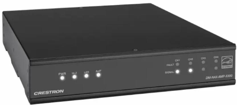
• Audio-over-IP (AoIP) amplifier
- Native Dante® mode
• Full DSP capabilities
• Streamlined configuration through a web interface
- ENERGY STAR® certified power amplifier
- 1 RU high, half-rack width form factor supports surface and rack mounting
- Configurable for Lo-Z (4/8 Ω) or Hi-Z (70V or 100V) operation
- Configurable for 4 x up to 75 W output, 2 x up to 150 W output, 1 x up to 300 W (bridged) out and 2 x up to 75 W + 1 x up to 150 W (bridged) output
- Matrix mixing of any input to any output
• Always On feature allows constant on connection with very low power consumption
- Connects directly to a managed network to route to or from DM NAX/DM NVX®, AES67, or Dante devices
• Supports mic/line level analog inputs and balanced/unbalanced line level outputs
- Individual zone power control and global standby
- Seamless Crestron system integration with Crestron Home® OS and SIMPL Windows programming
Audio-over-IP
DM NAX takes audio distribution to a whole new level by putting it on the network. The DM-NAX-AMP-X300 sends and receives DM NAX, Dante, and AES67 encoded audio over a standard IP network. A single DM NAX system can handle audio distribution between 32 DM NAX devices and
supports up to 256 audio output zones. DM NAX devices can seamlessly pull and distribute the audio from DM NVX sources.
Digital Signal Processing (DSP)
The DM-NAX-AMP-X300 has two DSP modes. Residential mode enables the quick and easy configuration of layout, speaker protection output limits, and speaker profiles for each zone. In Commercial mode, make full use of the DM-NAX-AMP-X300's true mixing matrix as well as advanced options for equalization and dynamics processing on each individual speaker, line, and network channel.
Encoder and Decoder Functionality
The DM-NAX-AMP-X300 can operate as a network AV encoder and decoder. The local input sources on one amplifier can be sent as AoIP streams to DM NAX, Dante, or AES67 capable devices. Simultaneously, the DM-NAX-AMP-X300 can receive AoIP streams from these same devices and decode them for local output.
Lo-Z (4/8 Ω) and Hi-Z (70V or 100V) Output
The DM-NAX-AMP-X300 is a 4-channel amplifier (up to 75 W per channel) which can also be configured for 3-channel bridged operation (up to 75 W per single ended channel and up to 150 W for the bridged channel), 2-channel bridged operation (up to 150 W per channel), or 1 channel bridged operation (up to 300 W). A choice of Lo-Z outputs to drive 4- or 8- speakers, or Hi-Z outputs to drive a distributed speaker system (70V or 100V) can be used. Balanced/Unbalanced inputs are provided for connection to two stereo or four mono sources through detachable terminal blocks.
ENERGY STAR® Certified
An energy-efficient design enables the DM-NAX-AMP-X300 to meet demanding ENERGY STAR requirements. In addition to its high efficiency under operation, the amplifier draws no added inrush current during power-up, thereby reducing AC circuit requirements and allowing multiple amplifiers to be connected to a single switched circuit. To reduce energy usage further, the DM-NAX-AMP-X300 can be configured to enter a low-power standby state if no input signal is detected on either channel for 25 minutes. Signal detection sensitivity has been optimized to improve response time when triggering the amplifier to the on state, allowing it to return to full operation within a half-second. The REMOTE input can be connected to a contact closure to place the amplifier outputs in controlled standby mode.
Modular Design
The DM-NAX-AMP-X300 is housed in a half-width rack-mountable form factor that can be installed individually or ganged together in a single rack space. The amplifier is high-density stackable with other Crestron modular amps, allowing multiple units to be installed vertically in an equipment rack without needing extra ventilation space. Rack and surface mount parts are included, so no additional mounting accessories or rack shelves are required.
Whether mounting in a rack, attaching to a flat surface, or placing on a shelf, it is easy to combine tw amplifiers into a single, full rack-width assembly.
Fully Protected
The DM-NAX-AMP-X300 features protection against overheating, shorted or overloaded speaker lines, excessive input signals, and other faults. In the case of a shorted speaker line or overheating condition, paired outputs mute automatically until the fault condition is resolved. In the event of a prolonged fault, all outputs mute and the amplifier shuts down.
DM-NAX-AUD-IO
The DM-NAX-AUD-IO is a DM NAX ^® encoder and decoder with support for analog line-level audio input and output. The device is housed in a versatile form factor that can be mounted in a single-gang standard electrical box, under a table, or on a rack rail. An additional polycarbonate label is included with rotated text to make the front panel more legible in electrical box installations. The rear panel of the device features an Ethernet connection for PoE, Audio over IP (AoIP), and control.

- Line-level, balanced/unbalanced analog audio input and output via detachable terminal block connectors
• Power over Ethernet (PoE) network powered - Mountable in a standard US electrical box, under a table, or on a rack rail via included hardware
- Connects directly to a managed network to route to or from other DM NAX® and DM NVX® devices
- Interoperable with Dante® audio networking devices via AES67 compatibility
- Streamlined configuration through a web interface
- Seamless Crestron system integration with SIMPL Windows programming
Audio-over-IP
DM NAX takes audio distribution to a whole new level by putting it on the network. The
DM-NAX-AUD-IO sends and receives DM NAX and AES67 encoded audio over a standard IP network. A single DM NAX system can handle audio distribution between 32 DM NAX devices and supports up to 256 audio output zones. DM NAX devices can seamlessly pull and distribute the audio from DM NVX sources.
Digital Signal Processing (DSP)
DSP capabilities such as bass and treble boost and cut, loudness, adjustable delay, tone profiles, and a full 10-band EQ per output are available on each output channel of the DM-NAX-AUD-IO.
Encoder and Decoder Functionality
The DM-NAX-AUD-IO can operate as a network AV encoder and decoder. The local input sources on the adapter can be sent as AoIP streams to DM NAX, Dante, or AES67 capable devices. Simultaneously, the DM-NAX-AUD-IO can receive AoIP streams from these same devices and decode them for local output.
DM-NAX-AUD-USB
The DM-NAX-AUD-USB is a DM NAX ^® encoder and decoder with support for USB audio and analog line-level audio input and output. The device is housed in a versatile form factor that can be mounted in a single-gang standard electrical box, under a table, or on a rack rail. An additional polycarbonate label is included with rotated text to make the front panel more legible in electrical box installations. Two 1/8 in (3.5 mm) TRS connectors for analog line-level audio input and output are also included on the front panel. The rear panel of the device features an Ethernet connection for PoE, Audio over IP (AoIP), and control.

- USB Audio Class 1 (UAC1) device with bidirectional stereo USB audio support
• Power over Ethernet (PoE) network powered
• Line-level, unbalanced analog audio input and output via 1/8 in. (3.5 mm) TRS connectors - Mountable in a standard US electrical box, under a table, or on a rack rail via included hardware
- Connects directly to a managed network to route to or from other DM NAX® and DM NVX® devices
- Interoperable with Dante® audio networking devices via AES67 compatibility
- Streamlined configuration through a web interface
- Seamless Crestron system integration with SIMPL Windows programming
USB Audio
A USB-C® connector is built-in to the front panel of the DM-NAX-AUD-USB, allowing for bidirectional stereo USB audio transfer at rates up to 24-bit/48 kHz. This stereo signal can be output as a DM NAX AoIP stream onto the network or as an unbalanced line-level analog signal from the local 1/8 in. (3.5 mm) audio output connector.
Audio-over-IP
DM NAX takes audio distribution to a whole new level by putting it on the network. The DM-NAX-AUD-USB sends and receives DM NAX and AES67 encoded audio over a standard IP network. A single DM NAX system can handle audio distribution between 32 DM NAX devices and supports up to 256 audio output zones. DM NAX devices can seamlessly pull and distribute the audio from DM NVX sources.
Digital Signal Processing (DSP)
DSP capabilities such as bass and treble boost and cut, loudness, adjustable delay, tone profiles, and a full 10-band EQ per output are available on each output channel of the DM-NAX-AUD-USB.
Encoder and Decoder Functionality
The DM-NAX-AUD-USB can operate as a network AV encoder and decoder. The local input sources on the adapter can be sent as AoIP streams to DM NAX, Dante, or AES67 capable devices. Simultaneously, the DM-NAX-AUD-USB can receive AoIP streams from these same devices and decode them for local output.
DM-NAX-BTIO-1G
The DM-NAX-BTIO-1G is a DM NAX ^® encoder and decoder with support for Bluetooth ^® wireless and analog line-level wired audio input and output, housed in a single-gang wall plate form factor. The front panel features an OLED display and four buttons for device pairing and menu navigation. Two 1/8 in. (3.5 mm) TRS connectors for stereo unbalanced analog line-level audio input and output are concealed under a front panel door. The rear panel of the wall plate features an Ethernet connection for PoE, Audio over IP (AoIP), and control.
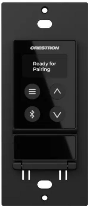
• Built-in Bluetooth® wireless audio input support
- Front panel OLED display provides metadata readout and device setup menus
- Single-gang U.S. wall box installation
• Power over Ethernet (PoE) network powered
- Stereo unbalanced analog line-level audio input and output via 3.5 mm TRS connectors
- Mountable in a standard US electrical box or on a rack rail via included hardware
- Connects directly to a managed network to route to or from other DM NAX® and DM NVX® devices
- Interoperable with Dante® audio networking devices via AES67 compatibility
- Streamlined configuration through front panel push buttons and a web interface
- Seamless Crestron system integration with SIMPL Windows programming
Bluetooth® Wireless Connectivity
Bluetooth wireless audio support is built-in to the DM-NAX-BTIO-1G, allowing a stereo audio signal to be transmitted from a smart phone or other source device to the wall plate. This stereo signal can be output as a DM NAX AoIP stream onto the network or as an unbalanced line-level analog signal from the local 3.5 mm audio output connector. Metadata for the Bluetooth audio stream can be displayed on the front panel, and up to seven previous source device connections can be recalled.
Audio-over-IP
DM NAX takes audio distribution to a whole new level by putting it on the network. The DM-NAX-BTIO-1G sends and receives DM NAX and AES67 encoded audio over a standard IP network. A single DM NAX system can handle audio distribution between 32 DM NAX devices and supports up to 256 audio output zones. DM NAX devices can seamlessly pull and distribute the audio from DM NVX sources.
Encoder and Decoder Functionality
The DM-NAX-BTIO-1G can operate as a network AV encoder and decoder. The local input sources on the wall plate can be sent as AoIP streams to DM NAX, Dante, or AES67 capable devices. Simultaneously, the DM-NAX-BTIO-1G can receive AoIP streams from these same devices and decode them for local output.
Front Panel Controls and Display
The DM-NAX-BTIO-1G features four front panel push buttons and a 128 x 64 dot matrix OLED display. The push buttons allow local volume control and Bluetooth pairing, with volume feedback and pairing status reflected in real time on the display. Metadata for Bluetooth media and basic configuration menus are also shown on the display.
Both the display and push buttons can be disabled via the configuration web interface or programming for applications where a more discreet or secure installation is required.
Specifications
Refer to the following sections for more information on the specifications for various DM NAX devices.
• DM-NAX-2XLRI-1G
- DM-NAX-8ZSA
- DM-NAX-4ZSA-50
- DM-NAX-4ZSP
- DM-NAX-16AIN
- DM-NAX-AMP-X300
• DM-NAX-AUD-IO
• DM-NAX-AUD-USB
- DM-NAX-BTIO-1G
DM-NAX-2XLRI-1G Specifications
Product specifications for the DM-NAX-2XLRI-1G are provided below.
Specifications
Audio
Input Signal Types Balanced/unbalanced analog line/mic-level; DM NAX/AES67 audio-over-IP
Output Signal Types Balanced/unbalanced analog line-level; DM NAX/AES67 audio-over-IP
Source Compensation ±10.0 dB per input Input Monitoring Source Signal Detect
Frequency Response (at from mic-level input: 20 Hz to 20 kHz ±1.0 dB; line-level output) From line-level input: 20 Hz to 20 kHz +0.1/-1.0 dB
THD+N (at line-level output) From mic-level input: 0.3% @ 1 kHz, max output From line-level input: 0.005% @ 1 kHz, max output
S/N Ratio (at line-level output) From analog input: 105 dB, 20 Hz to 20 kHz, A-weighted; From digital input: 111 dB, 20 Hz to 20 kHz, A-weighted
Balance Control Left/right adjustable
EQ Filter Types EQ, High Pass, Low Pass, Treble Shelf, Bass Shelf, Notch
EQ Center Frequency 10 Hz to 20 kHz per band
EQ Gain +20/-40 dB per band
EQ Bandwidth 0.1 to 4.0 octaves per band
Connectors
INPUTS 1-2 (2) Balanced XLR input ports
Line or microphone-level audio inputs;
Mic-level maximum gain: 60 dB
Mic-level maximum signal level: 2Vrms;
Mic-level channel separation: 70 dB @ 60 dB gain @ 1 kHz;
Line-level maximum signal level: +21 dBu (8.7Vrms)
Impedance: >10 kΩ;
+48V phantom power is available when used as mic-level inputs
OUTPUT L-R (1) 5-pin 3.5 mm screw terminal block;
Balanced line-level audio output;
Pins 1-2: Left channel output;
Pin 3: Shared ground;
Pins 4-5: Right channel output;
Maximum signal level: +14.7 dBu (4.2Vrms)
Impedance: 200 Ω;
Channel separation: 100 dB @ 1 kHz
G (1) 6-32 screw;
Chassis ground lug
ETHERNET PoE (1) 8-pin RJ-45 connector, female;
100BASE-TX/1000BASE-T Ethernet port
Controls and Indicators
ETHERNET PoE Left amber LED indicates 1000 Mb link status;
Left green LED indicates 100 Mb link status;
Flashing right amber LED indicates Ethernet activity
SETUP (1) Push button: Used for factory reset procedures;
(1) LED, illuminates red when the button is pressed, flashes red when reset has been initiated
Power
PoE IEEE 802.3af Class O (12.95 W) compliant;
Compatible with IEEE 802.3af compliant Ethernet switch or third-party PoE compliant PSE
Power Consumption 2.9 W
Environmental
Temperature 32° to 95° F (0° to 35° C)
Humidity 10% to 95% RH (noncondensing)
Heat Dissipation 9.9 BTU/hr
Construction
Chassis Metal, black and silver finish, vented sides
Mounting
Mountable on the following:
1-gang U.S. electrical box or plaster ring (not included), 3.5 in. (26 mm) electrical box depth recommended;
Rack rail
Dimensions
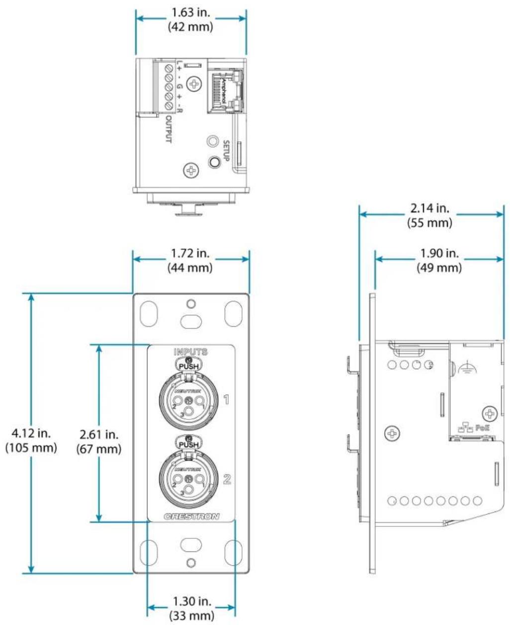
Height 4.12 in. (105 mm)
Width 1.72 in. (44 mm)
Depth 2.14 in. (55 mm)
Weight
6 oz. (170 g)
Compliance
Regulatory Model: M1845004
IC, FCC Part 15 Class B digital device
Dimension Drawing
DM-NAX-8ZSA Specifications
Product specifications for the DM-NAX-8ZSA are provided below.
Specifications
Audio
| Input Signal Types 4 stereo analog (RCA); | |
| 4 digital S/PDIF (2 TOSLINK® and 2 Coaxial) | |
| Output Signal Types | 4 stereo analog outputs (mirrors speaker zone outputs 1-4), Outputs 1 and 2 have a balanced 5-pin stereo Phoenix connection and an unbalanced RCA connection |
| Sampling Rates and Bit | Digital Input (Coaxial): Up to 192 kHz, |
| Depths | 24-bit;Digital Input (Optical): Up to 96 kHz,24-bit;Media Players: Up to 192 kHz, 24-bit |
| Source Compensation ±10.0 dB per input | |
| Input Monitoring Source Signal Detect | |
| Output Power 150 Watts per channel at 8 Ohms;300 Watts per channel at 4 Ohms;500 Watts per channel at 8 Ohms bridged | |
| Amplifier Monitoring Over Current, Over/Under Voltage, Over Temperature, DC Offset, Clipping | |
| Frequency Response 20 Hz to 20 kHz ±0.6 dB | |
| THD 0.006% | |
| S/N Ratio 110 dB digital in, 108 dB analog in | |
| Stereo Separation 85 dB @ 1 kHz, 8 ohm;80 dB @ 1 kHz, 4 ohm | |
| Zone Separation 100 dB @ 1 kHz, 8 ohm;95 dB @ 1 kHz, 4 ohm | |
| Zone Volume Level Control | -80.0 to +20.0 dB, adjustable from 0% to 100% plus mute |
| Bass Control | ±12.0 dB |
| Treble Control | ±12.0 dB |
| Loudness Compensation | On/Off |
| Dynamic Range Control | Off/Low/Medium/High |
| Balance Control | Left/right adjustable |
| Zone Configuration | Stereo Single Ended, Mono Single Ended, Stereo Bridged, Mono Bridged, Bridged 2.1, and Bridged 2.1 with Bridged Sub |
| Power Limiting | Configurable 5 to 150 Watts @ 8 Ohms;5 to 300 Watts @ 4 Ohms;5 to 500 Watts @ 8 Ohms bridged |
| Tone Profiles | Flat, Classical, Jazz, Pop, Rock, Spoken Word |
EQ Filter Types EQ, High Pass, Low Pass, Treble Shelf, Bass Shelf, Notch
EQ Center Frequency 10 to 20,000 Hz per band
EQ Gain +20/-40 dB per band
EQ Bandwidth 0.1 to 4.0 octaves per band
Bus Volume Offset ±12.0 dB per zone for output bussing
Communications
Ethernet For control, AoIP, and or console, 100/1000 Mbps, auto-switching, auto-negotiating, auto-discovery, full/half duplex, DHCP
USB For configuration management
Connectors
SPDIF SOURCES 1 - 2 (2) JIS F05 female (TOSLINK) optical fiber connector; S/PDIF optical digital audio input
SPDIF SOURCES 3 - 4 (2) RCA female; S/PDIF coaxial digital audio inputs; Input Impedance: 75 Ohms
ANALOG SOURCES L/R 5 (8) RCA female comprising (4) unbalanced stereo line-level audio inputs; -8 Input Impedance: 10k Ohms; Maximum Input Level: 2 Vrms
ANALOG OUT L/R 1 - 4 (8) RCA connectors, female; Comprises (4) unbalanced line-level stereo audio outputs (mirror corresponding amplified output pairs 1 - 4); Output Impedance: 100 Ohms; Maximum Output Level: 2 Vrms
ANALOG OUT L/R 1 - 2 (2) 5-pin 3.5mm detachable terminal blocks; Balanced stereo line-level audio outputs (mirror corresponding unbalanced output pairs 1 - 2); Output Impedance: 150 Ohms; Maximum Output Level: 4 Vrms
Ethernet 1 (1) 8-wire RJ45 female; 100Base-T/1000Base-TX Ethernet port
Ethernet 2 (1) 8-wire RJ45 female; 100Base-T/1000Base-TX Ethernet port USB (1) USB Type B connector, female;
USB computer console port (cable included); For setup only
100-240V\~50/60Hz (1) IEC 60320 C14 main power inlet, mates with removable power cord (included) Universal AC
G 6-32 screw, chassis ground lug
SPEAKER OUTPUTS L/R 1 (16) 2-pin 7.62mm 15A detachable terminal blocks;
- 8 Power amplifier outputs; Wire Size: Terminals accept up to 12AWG
Controls and Indicators
| PWR (1) LED. Amber indicates that the device is booting. White indicates that the device is switched on with audio passing. Red indicates that the device is in standby mode. Off indicates that there is no power from the power supply. | |
| LAN (1) LED. White indicates that the device is switched on and has a valid IP address. Off indicates that the device is not connected to a network or the IP address is invalid. | |
| NAX | (1) LED. White indicates that AoIP is ready to pass and the unit's PTP clock is synced.Off indicates that no AoIP is passing to or from and/or PTP is not synced. |
| SOURCE 1-8 | (8) LEDs. White indicates signal presence on the specified input/source. Red indicates there is a clipping on an analog input or a bitstream issue on a digital input. Off indicates that there is no signal detected on the specified input/source. |
| ZONE 1-8 (8) LEDs. White indicates there is audio output on the indicated zone. Red indicates a fault due to clipping, over current, over temperature, or low voltage. | |
| SETUP (1) LED. Blinking red indicates that a network reset or factory restore has been initiated via the adjacent SETUP button. | |
Power
Power Consumption 240 W (All channels driven at 1/8th power, 8 ohms)
Environmental
Temperature 32° to 104°F (0° to 40°C) Humidity 10% to 90% RH (non-condensing)
Heat Dissipation 450 BTU/hr
Construction
Chassis Metal, black and silver finish, vented sides Mounting 2 RU rack-mountable
Dimensions
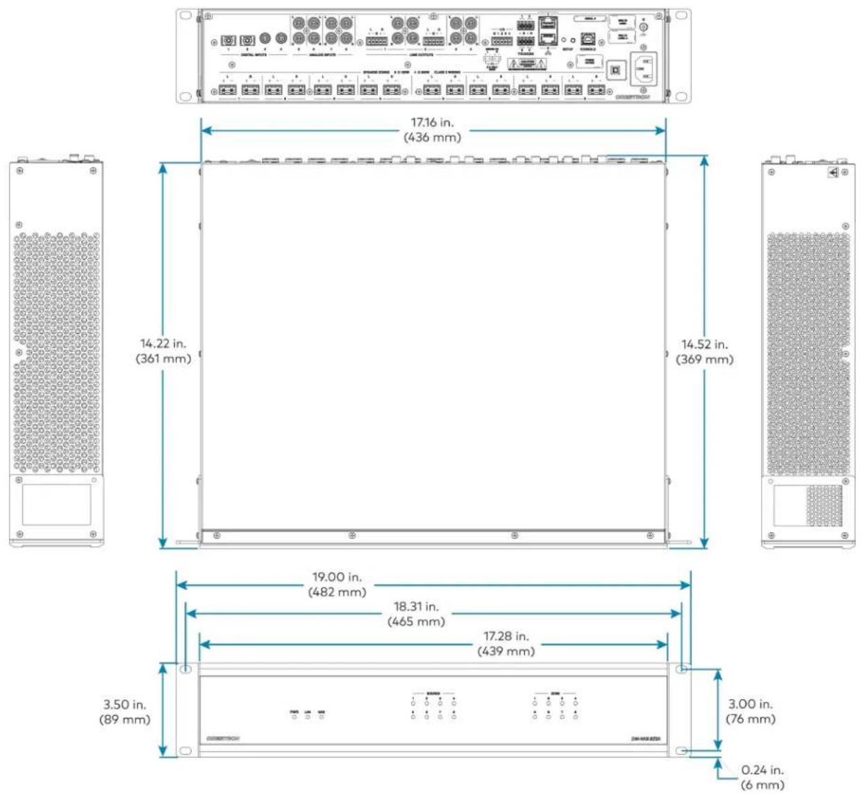
| Height | 3.50 in. (89 mm) |
| Width | 19 in. (482 mm) |
| 17.28 in. (439 mm) without rack ears | |
| Depth | 14.52 in. (369 mm) |
Weight
28 lb (12.70 kg)
Compliance
Regulatory Model: M1845004
FCC Part 15 Class B digital device, IC Class B, CE, ETL listed
Dimension Drawing
DM-NAX-4ZSA-50 Specifications
Product specifications for the DM-NAX-4ZSA-50 are provided below.
Specifications
Audio
Input Signal Types 2 stereo analog (RCA); 2 digital S/PDIF (1 TOSLINK® connection and 1 coaxial connection, PCM only)
Output Signal Types 4 stereo speaker-level amplified outputs; 1 stereo analog line-level output
Sampling Rates and Bit Digital Input (Coaxial): Up to 192 kHz, 24-bit;
Depths Digital Input (Optical): Up to 192 kHz, 24-bit;
Media Players: Up to 192 kHz, 24-bit
Source Compensation ±10.0 dB per input
Input Monitoring Source Signal Detect
Output Power 50 W per channel at 4 or 8 Ohms
Amplifier Monitoring Over Current, Over/Under Voltage, Over Temperature, DC Offset, Clipping
Frequency Response 20 Hz to 20 kHz ±0.5 dB
THD 0.006%
S/N Ratio 110 dB digital in; 108 dB analog in
Stereo Separation 95 dB @ 1 kHz, 8 Ohm; 90 dB @ 1 kHz, 4 Ohm
Zone Separation 100 dB @ 1 kHz, 8 Ohm; 95 dB @ 1 kHz, 4 Ohm
Zone Volume Level Control -80.0 to +20.0 dB, adjustable from 0% to 100% plus mute
Bass Control ±12.0 dB
Treble Control ±12.0 dB
Loudness Compensation On/Off
Dynamic Range Control Off/Low/Medium/High
Balance Control Left/right adjustable
Zone Configuration Stereo Single Ended; Mono Single Ended
Power Limiting Configurable 5 to 50 W @ 4 or 8 Ohms
Tone Profiles Flat, Classical, Jazz, Pop, Rock, Spoken Word
EQ Filter Types EQ, High Pass, Low Pass, Treble Shelf, Bass Shelf, Notch
EQ Center Frequency 10 Hz to 20 kHz per band
EQ Gain -40.0 to +20.0 dB per band
EQ Bandwidth 0.1 to 4.0 octaves per band
Bus Volume Offset ±12.0 dB per zone for output bussing
Communications
Ethernet For control, AoIP, and/or console;
100/1000 Mbps, auto-switching, auto-negotiating, auto-discovery, full/half duplex,
DHCP
Connectors
SPEAKER ZONES 1-4 (4) 4-pin 5.08 mm detachable terminal blocks;
Stereo speaker-level audio outputs;
Maximum Wire Size: 12 AWG
LINE OUT 5 (2) RCA female comprising (1) unbalanced stereo line-level audio output;
Output Impedance: 100 Ohms;
Maximum Output Level: 2Vrms
DIGITAL INPUT 1 (1) RCA female;
S/PDIF coaxial digital audio input;
Input Impedance: 75 Ohms
DIGITAL INPUT 2 (1) JIS F05 female TOSLINK® optical fiber connector;
S/PDIF optical digital audio input
ANALOG INPUTS 3-4 (4) RCA female comprising (2) unbalanced stereo line-level audio inputs;
Input Impedance: 10 kOhms;
Maximum Input Level: 2Vrms
ETHERNET 1-2 (2) 8-pin RJ-45 connectors, female;
100BASE-TX/1000BASE-T Ethernet port;
Green LED indicates Ethernet link status;
Flashing amber LED indicates Ethernet activity
100-240 VAC 1.0-0.4A (1) 100-240V\~50/60Hz Universal AC; IEC 60320 C14 main power inlet, mates with
50/60HZ removable power cord (included)
Controls and Indicators
PWR (1) LED;
Amber indicates that the device is booting;
White indicates that the device is switched on with audio passing;
Red indicates that the device is in standby mode
LAN (1) White LED;
Indicates that the device has a valid IP address
NAX (1) White LED;
White indicates that audio-over-IP traffic is passing in or out of the DM NAX unit
SOURCE 1-4 (4) LEDs;
White indicates signal presence on the specified input/source;
Red indicates there is clipping on the specified input/source
ZONE 1-5 (5) LEDs;
White indicates there is audio output on the indicated zone;
Red indicates a fault due to clipping, over current, over temperature, or low voltage
SETUP (1) Push button: Pressing and holding the SETUP button for
15 seconds with power supplied clears network settings and restores the default DHCP mode;
To perform a factory restore, press and hold the SETUP button with power disconnected, then connect the power supply and continue to hold the SETUP button for 30 seconds;
(1) LED, illuminates red when the button is pressed, flashes red when reset has been initiated
Power
Main Power 1.0-0.4A @ 100-240VAC, 50/60 Hz
Power Consumption 50 W (all channels driven at 1/8 output power, 8 Ohms)
Environmental
Temperature 32° to 104°F (0° to 40°C)
Humidity 10% to 90% RH (non-condensing)
Heat Dissipation 85 BTU/hr (all channels driven at 1/8 output power, 4 Ohms)
Construction
Chassis Metal, black and silver finish, vented front and rear panels
Mounting 1 RU rack-mountable
Dimensions
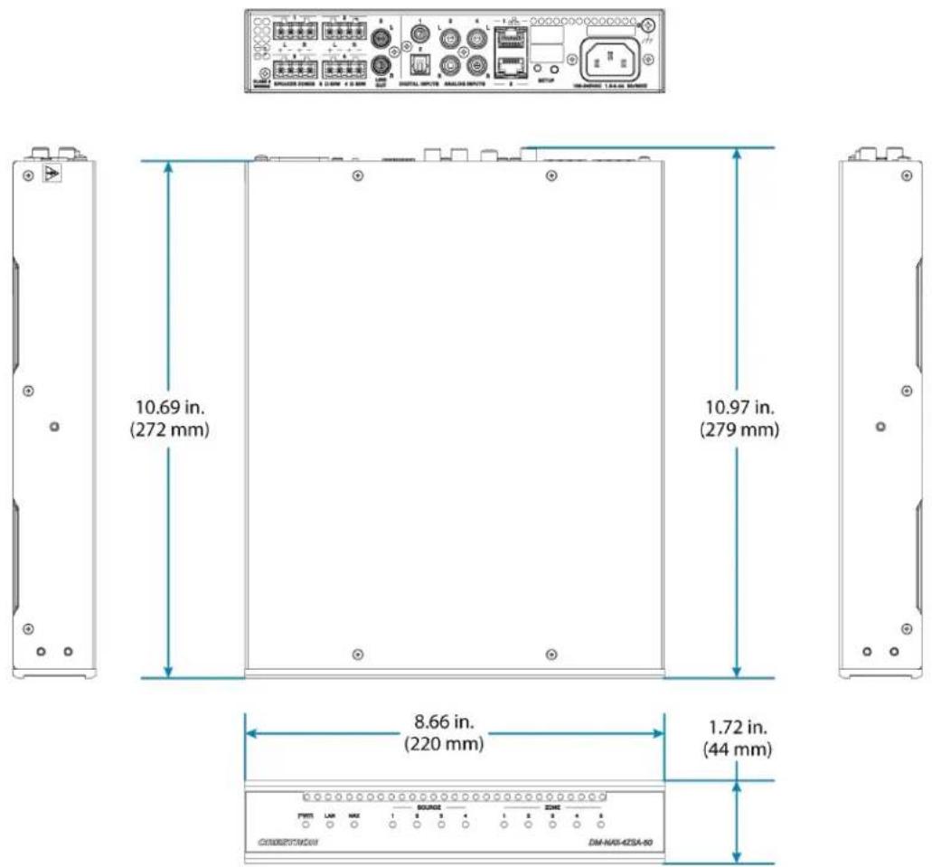
Height 1.72 in. (44 mm)
Width 8.66 in. (220 mm)
Depth 10.97 in. (279 mm)
Weight
4.15 lb (1.88 kg)
Compliance
Regulatory Model: M1845004
Intertek® Listed for US & Canada, CE, IC, FCC Part 15 Class B digital device
Dimension Drawing
DM-NAX-4ZSP Specifications
Product specifications for the DM-NAX-4ZSP are provided below.
Specifications
Audio
| Input Signal Types 4 stereo analog (RCA); | |
| 4 digital S/PDIF (2 TOSLINK® and 2 Coaxial) | |
| Output Signal Types | 4 stereo analog outputs, Outputs 1 and 2 have a balanced 5-pin stereo Phoenix connection and an unbalanced RCA connection |
| Sampling Rates and Bit | Digital Input (Coaxial): Up to 192 kHz, |
| Depths | 24-bit;Digital Input (Optical): Up to 96 kHz,24-bit;Media Players: Up to 192 kHz, 24-bit |
| Source Compensation ±10.0 dB per input | |
| Input Monitoring Source Signal Detect | |
| Frequency Response 20 Hz to 20 kHz ±0.2 dB | |
| THD 0.006% | |
| S/N Ratio 110 dB digital in, 108 dB analog in | |
| Zone Volume Level Control -80.0 to +20.0 dB, adjustable from 0% to 100% plus mute | |
| Bass Control ±12.0 dB | |
| Treble Control ±12.0 dB | |
| Loudness Compensation On/Off | |
| Dynamic Range Control | Off/Low/Medium/High |
| Balance Control | Left/right adjustable |
| Tone Profiles | Flat, Classical, Jazz, Pop, Rock, Spoken Word |
| EQ Filter Types | EQ, High Pass, Low Pass, Treble Shelf, Bass Shelf, Notch |
| EQ Center Frequency | 10 to 20,000 Hz per band |
| EQ Gain | +20/-40 dB per band |
| EQ Bandwidth | 0.1 to 4.0 octaves per band |
| Bus Volume Offset | ±12.0 dB per zone for output bussing |
Communications
Ethernet For control, AoIP, and or console, 100/1000 Mbps, auto-switching, auto-negotiating, auto-discovery, full/half duplex, DHCP
USB For configuration management
Connectors
SPDIF SOURCES 1 - 2 (2) JIS F05 female (TOSLINK) optical fiber connector; S/PDIF optical digital audio input
SPDIF SOURCES 3 - 4 (2) RCA female; S/PDIF coaxial digital audio inputs; Input Impedance: 75 Ohms
ANALOG SOURCES L/R 5 (8) RCA female comprising (4) unbalanced stereo line-level audio inputs; -8 Input Impedance: 10k Ohms; Maximum Input Level: 2 Vrms
ANALOG OUT L/R 1 - 4 (8) RCA connectors, female; Comprises (4) unbalanced line-level stereo audio outputs (mirror corresponding amplified output pairs 1 - 4); Output Impedance: 100 Ohms; Maximum Output Level: 2 Vrms
ANALOG OUT L/R 1 - 2 (2) 5-pin 3.5mm detachable terminal blocks; Balanced stereo line-level audio outputs (mirror corresponding unbalanced output pairs 1 - 2); Output Impedance: 150 Ohms; Maximum Output Level: 4 Vrms
Ethernet 1 (1) 8-wire RJ45 female; 100Base-T/1000Base-TX Ethernet port
Ethernet 2 (1) 8-wire RJ45 female; 100Base-T/1000Base-TX Ethernet port
USB (1) USB Type B connector, female; USB computer console port (cable included); For setup only
100-240V\~50/60Hz (1) IEC 60320 C14 main power inlet, mates with removable power cord (included) Universal AC
G 6-32 screw, chassis ground lug
Controls and Indicators
PWR (1) LED. White indicates that the device is switched on with audio passing. Red indicates that the device is in standby mode. Off indicates that there is no power from the power supply.
LAN (1) LED. White indicates that the device is switched on and has a valid IP address. Off indicates that the device is not connected to a network or the IP address is invalid.
NAX (1) LED. White indicates that AoIP is ready to pass and the unit's PTP clock is synced. Off indicates that no AoIP is passing to or from and/or PTP is not synced.
SOURCE 1-8 (8) LEDs. White indicates signal presence on the specified input/source. Red indicates there is a clipping on an analog input or a bitstream issue on a digital input. Off indicates that there is no signal detected on the specified input/source.
ZONE 1-4 (4) LEDs. White indicates there is audio output on the indicated zone. Red indicates clipping is detected on the output audio.
SETUP (1) LED. Blinking red indicates that a network reset or factory restore has been initiated via the adjacent SETUP button.
Power
Power Consumption 15.9 W
Environmental
Temperature 32° to 104°F (0° to 40°C)
Humidity 10% to 90% RH (non-condensing)
Heat Dissipation 57 BTU/hr
Construction
Chassis Metal, black and silver finish, vented sides
Mounting 1 RU rack-mountable
Dimensions
Height 1.73 in. (44 mm)
Width 19 in. (482 mm)
17.28 in. (439 mm) without rack ears
Depth 14.50 in. (368 mm)
8.06 lb (3.65 kg)
Compliance
Regulatory Model: M1845004
FCC Part 15 Class B digital device, IC Class B, CE, ETL listed
Dimension Drawing

DM-NAX-16AIN Specifications
Product specifications for the DM-NAX-16AIN are provided below.
Specifications
Audio
| Input Signal Types | 8 stereo unbalanced analog (RCA) includes (4) 5-pin phoenix balanced connector;8 digital SPDIF (4 TOSLINK® and 4 Coaxial) |
Source Compensation ±10.0 dB per input
Input Monitoring Source Signal Detect
THD 0.002%
S/N Ratio 110 dB digital in, 108 dB analog in
Frequency Response 20 Hz to 20 kHz ( ± 0.6 dB)
Supported Sample Rates Coaxial: Up to 192 kHz;
Optical: 192 kHz
Communications
| Ethernet For control, AoIP, and or console, 100/1000 Mbps, auto-switching, auto-negotiating, auto-discovery, full/half duplex, DHCP |
USB For configuration management
Connectors
| ANALOG SOURCES L/R | (8) RCA female comprising (4) unbalanced stereo line-level audio inputs; |
| 1 - 8 | (4) 5-pin phoenix balanced connectorInput Impedance: 10k Ohms;Maximum Input Level: 2 Vrms |
| SPDIF SOURCES 9 - 12 | (4) JIS F05 female (TOSLINK) optical fiber connector;S/PDIF optical digital audio input |
| SPDIF SOURCES 13 - 16 | (4) RCA female;S/PDIF coaxial digital audio inputs;Input Impedance: 75 Ohms |
| Ethernet 1 | (1) 8-wire RJ45 female; 100Base-T/1000Base-TX Ethernet port |
| Ethernet 2 | (1) 8-wire RJ45 female; 100Base-T/1000Base-TX Ethernet port |
| USB (1) USB Type B connector, female;USB computer console port (cable included);For setup only | |
| 100-240V~50/60HzUniversal AC | (1) IEC 60320 C14 main power inlet, mates with removable power cord (included) |
| G | 6-32 screw, chassis ground lug |
Controls and Indicators
| PWR (1) LED. Amber indicates that the device is booting. White indicates that the device is switched on with audio passing. Red indicates that the device is in standby mode. Off indicates that there is no power from the power supply. | |
| LAN (1) LED. White indicates that the device is switched on and has a valid IP address. Off indicates that the device is not connected to a network or the IP address is invalid. | |
| NAX | (1) LED. White indicates that AoIP is ready to pass and the unit's PTP clock is synced.Off indicates that no AoIP is passing to or from and/or PTP is not synced. |
| SOURCE 1-16 (16) LEDs. White indicates signal presence on the specified input/source. Red indicates there is a clipping on an analog input or a bitstream issue on a digital input.Off indicates that there is no signal detected on the specified input/source. | |
| SETUP (1) LED. Blinking red indicates that a network reset or factory restore has been initiated via the adjacent SETUP button. | |
Power
Power Consumption 20 Watts
Environmental
| Temperature 32° to 104°F (0° to 40°C) |
| Humidity 10% to 90% RH (non-condensing) |
| Heat Dissipation 70 BTU/hr |
Construction
Chassis Metal, black and silver finish, vented sides Mounting 1 RU rack-mountable
Dimensions
| Height | 1.25 in. (32 mm) |
| Width | 19 in. (483 mm);17.28 in. (439 mm) without rack ears |
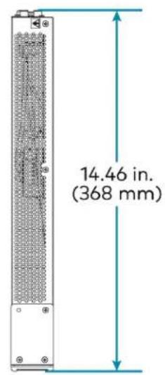
| Depth | 14.46 in. (368 mm) |
Weight
7.39 lb (3.35 kg)
Compliance
Regulatory Model: M1845004
FCC Part 15 Class B digital device, CE, ETL listed
Dimension Drawing


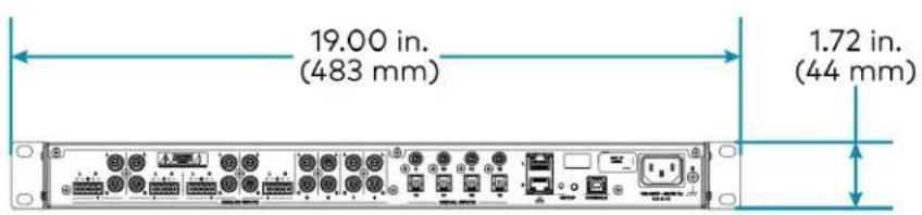
DM-NAX-AMP-X300 Specifications
Product specifications for the DM-NAX-AMP-X300 are provided below.
Specifications
Audio
Input Signal Types Balanced/unbalanced analog line/mic-level and AoIP streams.
Balanced Analog Input Maximum signal level: +21 dBu (8.7 Vrms)
Impedance: >10k Ohms
f Response: 20 Hz to 20 kHz±0.5 dB
THD+N: <0.005% @ 1 KHz
S/N Ratio: 105 dB A-weight
Channel Separation: 100 dB @ 1 KHz
Mic Input Maximum gain: 60 dB
Impedance: >10k Ohms
f Response: 20 Hz to 20 kHz±0.5 dB
THD+N: <0.005% @ 1 KHz @ 60 dB gain
S/N Ratio: 71 dB @ 60 dB gain A-weight
Channel Separation: 69 dB @ 60 dB gain @ 1 KHz
Balanced Analog Output Maximum signal level: +21 dBu (8.7 Vrms)
Impedance: 200 Ohms
f Response: 20 Hz to 20 kHz ±0.5 dB
THD+N: 0.005% @ 1 kHz at max output
S/N Ratio: 113 dB digital in, 105 dB analog in, 20 Hz -20 kHz, A-weight
Channel Separation: 100 dB @ 1 KHz
Speaker Output f Response: 20 Hz to 20 kHz ±0.5 dB at 1 W
High-Pass Filter (70V and 100V operation only): -3 dB @ 80 Hz, -12 dB/octave
THD+N: <0.1% at 1 kHz @ -3 dB full rated output power
S/N Ratio: >103 dB, 20 Hz to 20 kHz, balanced
Crosstalk: -75 dB at 1 kHz
Gain: 29 dB @ 8 Ω
Protection: Over current, under voltage, over temperature, DC offset, extreme high frequency
Go to Sleep Time: 25 minutes with no signal present (when set to POWER SAVER)
Wake Time: 0.5 s typical
Output Power Per Channel
| Mode 1 Channel Driven 2 Channels Driven 3 Channels Driven 4 Channels Driven | ||
| Lo-Z, 8 Ω (single ended) 150 W 150 W 75 W | 1 | 75 W |
| Lo-Z, 4 Ω (single ended) 200 W 150 W 75 W | 1 | 75 W |
| Lo-Z, 8 Ω Bridged 300 W 150 W 150 W | 1 | N/A |
| Hi-Z 70V 300 W 150 W N/A N/A | ||
| Hi-Z 100V | 300 W 150 W N/A N/A | |
NOTES:
- Total output power from all channels combined (simultaneously) is up to 300 W.
• Each mode will output power in watts up to the value listed in the table.
Connectors
| CH1-CH4 | (2) 4-pin 5.08 mm pitch, 12A plug with screw locking retainers;Power amplifier output;Terminals accept up to 12 AWG (3.31 mm) |
| NOTE: Output is direct-coupled, not transformer isolated. | |
| IN1-IN4 | (4) 3-pin 3.5 mm detachable terminal block;Balanced/unbalanced line or mic-level audio inputs;Maximum Input Level: 8.7 Vrms, +21 dBu;Input Impedance: 10k Ω Wake threshold is -65 dBu;Phantom power is available when used as mic-level inputs |
| OUT1-OUT4 | (4) 3-pin 3.5 mm detachable terminal block;Balanced/unbalanced line-level audio outputs;Maximum Output Level: 8.7 Vrms, +21 dBu |
| REMOTE | (1) 2-pin 3.5 mm detachable terminal block;Connect to dry contact closure to place amplifier in standby mode |
| G | (1) 6-32 screw;Chassis ground lug |
| 100-240V~ 1.2-0.6A 50/60 Hz | (1) IEC 60320 C14 main power inlet;Mates with removable power cord, included |
| Ethernet 1 | (1) 8-wire RJ45 female;100Base-T/1000Base-TX Ethernet port |
| Ethernet 2 | (1) 8-wire RJ45 female;100Base-T/1000Base-TX Ethernet port |
| Controls and Indicators | |
| PWR | (1) LED;White indicates amplifier is on and ready for use;Amber indicates the amplifier is booting;Red indicates amplifier is in standby |
HI-Z (1) White LED;
Indicates when Hi-Z mode is enabled (70V or 100V)
LAN (1) White LED;
Indicates that the device has a valid IP address
AoIP (1) White LED;
Indicates an active AoIP stream
FAULT (4) Red LEDs (one per speaker output);
Indicates that the input channel has a fault or is clipping
SIGNAL (4) White LEDs (one per speaker output);
Indicates an active input signal
LOCKOUT (1) Red LED;
Indicates that rear panel slide switches are being overridden by programmatic or web UI control
Lo-Z MODES (2) Slide switches, one switch controlling channels 1 and 2, and one switch
controlling channels 3 and 4;
Selects stereo, summed, or bridged operation:
- STEREO: The input signal received on each channel is sent to its respectively numbered speaker, line, and network output for use in applications where left and right channel separation is required.
- SUM: The input signals received on a pair of line inputs (1 + 2 or 3 + 4) are each routed to both channels of their respectively numbered speaker, line, and network output pair.
- BRIDGE: The input signals received on a pair of line inputs (1 + 2 or 3 + 4) are summed and sent to a bridged output (1 + 2 or 3 + 4) for use in high power applications.
Operations Mode (1) Slide switch;
Sets the amplifier for Lo-Z (4 or 8 Ω) or Hi-Z operation (70V or 100V)
Power Mode (1) Slide switch;
Selects Power Saver or Always On operation
SETUP (1) Red LED and push button;
Utilized in some restore procedures
Power
Main Power 1.2-0.6A @ 100-240VAC, 50/60 Hz
Power Consumption 75 W (All channels driven at 1/8th power, 8 ohms)
Environmental
| Temperature | 41 to 104°F (5° to 40°C) |
| Humidity | 10% to 90% RH (non-condensing) |
| Heat Dissipation | 130 BTU/hr |
Dimensions
| Height | 1.74 in. (44 mm) |
| Width | 9.38 in. (238 mm) |
Depth 11.03 in. (280 mm)
Weight
5.3 lb (2.4 kg)
Compliance
Regulatory Model: M1845004
UL® Listed for US & Canada, CE, IC, FCC Part 15 Class B digital device Note:
- 3 channel operation requires two single ended loads and one bridged load.
Dimension Drawings

DM-NAX-AUD-IO Specifications
Product specifications for the DM-NAX-AUD-IO are provided below.
Specifications
Audio
Input Signal Types Balanced/unbalanced stereo analog line-level; DM NAX/AES67 audio-over-IP
Output Signal Types Balanced/unbalanced stereo analog line-level; DM NAX/AES67 audio-over-IP
Source Compensation ±10.0 dB per input Input Monitoring Source Signal Detect
Frequency Response (at 20 Hz to 20 kHz ±0.5 dB line-level output)
THD+N (at line-level output) 0.005% @ 1 kHz, max output
S/N Ratio (at line-level output) From line-level input: 110 dB, 20 Hz to 20 kHz, A-weighted; From digital input: 113 dB, 20 Hz to 20 kHz, A-weighted
Balance Control Left/right adjustable
EQ Filter Types EQ, High Pass, Low Pass, Treble Shelf, Bass Shelf, Notch
EQ Center Frequency 10 to 20,000 Hz per band EQ Gain +20/-40 dB per band
EQ Bandwidth 0.1 to 4.0 octaves per band
Communications
Ethernet For control and PoE, AoIP, and/or console, 100/1000 Mbps, auto-switching, auto-negotiating, auto-discovery, full/half duplex, DHCP
Connectors
INPUTS (1) 5-pin 3.5 mm detachable terminal block; Balanced/unbalanced line-level audio inputs; Maximum Input Level: +21 dBu (8.7Vrms); Input Impedance: 10 kΩ
OUTPUTS (1) 5-pin 3.5 mm detachable terminal block; Balanced/unbalanced line-level audio outputs; Maximum Output Level: +21 dBu (8.7Vrms); Channel separation: 100 dB @ 1 kHz; Output Impedance: 400 Ω
G (1) 6-32 screw; Chassis ground lug
ETHERNET PoE (1) 8-pin RJ-45 connector, female;
100BASE-TX/1000BASE-T Ethernet port;
Controls and Indicators
| ETHERNET PoE Left amber LED indicates 1000 Mb link status;Left green LED indicates 100 Mb link status;Flashing right amber LED indicates Ethernet activity |
| SETUP (1) Push button: Used for factory reset procedures;(1) LED, illuminates red when the button is pressed, flashes red when reset has been initiated |
Power
| PoE IEEE 802.3af Class 0 (12.95 W) compliant;Compatible with IEEE 802.3af compliant Ethernet switch or third-party PoE compliant PSE |
Power Consumption 5 W
Environmental
| Temperature 32° to 104° F (0° to 40° C) |
| Humidity 10% to 95% RH (noncondensing) |
| Heat Dissipation 17 BTU/hr |
Construction
| Chassis Metal, black and silver finish |
| Mounting Mountable on the following via included hardware:1-gang U.S. electrical box or plaster ring (not included), 3.5 in. (26 mm) electrical box depth recommended;Rack rail;Surface mount |
Dimensions
| Height | 1.59 in. (41 mm) |
| Width | 2.60 in. (66 mm) |
| Depth | 2.11 in. (54 mm) |
Weight
7 oz. (199 g)
Compliance
| Regulatory Model: M1845004 |
| IC, FCC Part 15 Class B digital device |
Dimension Drawing


natural_image
Simple line drawing of a rectangular enclosure with two circular buttons at the top (no text or symbols)
DM-NAX-AUD-USB Specifications
Product specifications for the DM-NAX-AUD-USB are provided below.
Specifications
Audio
Input Signal Types USB stereo;
Unbalanced stereo analog line-level;
DM NAX/AES67 audio-over-IP
Output Signal Types USB stereo;
Unbalanced stereo analog line-level;
DM NAX/AES67 audio-over-IP
Source Compensation ±10.0 dB per input
Input Monitoring Source Signal Detect
Frequency Response (at 20 Hz to 20 kHz ±0.5 dB
line-level output)
THD+N (at line-level output) 0.005% @ 1 kHz, max output
S/N Ratio (at line-level output) From line-level input: 108 dB, 20 Hz to 20 kHz, A-weighted; From digital input: 111 dB, 20 Hz to 20 kHz, A-weighted
Balance Control Left/right adjustable
EQ Filter Types EQ, High Pass, Low Pass, Treble Shelf, Bass Shelf, Notch
EQ Center Frequency 10 to 20,000 Hz per band
EQ Gain +20/-40 dB per band
EQ Bandwidth 0.1 to 4.0 octaves per band
Communications
Ethernet For control and PoE, AoIP, and/or console, 100/1000 Mbps, auto-switching, auto-negotiating, auto-discovery, full/half duplex, DHCP
USB Bidirectional USB Audio Class 1 (UAC1) device connection, up to 24-bit/48 kHz stereo audio transfer
Connectors
| USB | (1) USB Type-C connector, female;UAC1 audio support;Enumerates as a Non-AEC Enabled Speakerphone |
| INPUT | (1) 1/8 in. 3.5 mm connector, female TRS;Unbalanced line-level audio input;Maximum input level: 2Vrms;Input Impedance: 10 kΩ |
OUTPUT (1) 1/8 in. 3.5 mm connector, female TRS; Unbalanced line-level audio output; Maximum output level: 2Vrms; Channel separation: 100 dB @ 1 kHz; Output impedance: 100 Ω
G (1) 6-32 screw;
Chassis ground lug
ETHERNET PoE (1) 8-pin RJ-45 connector, female; 100BASE-TX/1000BASE-T Ethernet port
Controls and Indicators
ETHERNET PoE Left amber LED indicates 1000 Mb link status; Left green LED indicates 100 Mb link status; Flashing right amber LED indicates Ethernet activity
SETUP (1) Push button: Used for factory reset procedures; (1) LED, illuminates red when the button is pressed, flashes red when reset has been initiated
Power
PoE IEEE 802.3af Class 0 (12.95 W) compliant; Compatible with IEEE 802.3af compliant Ethernet switch or third-party PoE compliant PSE
Power Consumption 5 W
Environmental
Temperature 32° to 104° F (0° to 40° C) Humidity 10% to 95% RH (noncondensing) Heat Dissipation 17 BTU/hr
Construction
Chassis Metal, black and silver finish Mounting Mountable on the following via included hardware: 1-gang U.S. electrical box or plaster ring (not included), 3.5 in. (26 mm) electrical box depth recommended; Rack rail; Surface mount
Dimensions
Height 1.59 in. (41 mm) Width 2.60 in. (66 mm) Depth 2.11 in. (54 mm)
Weight
7 oz. (199 g)
Regulatory Model: M1845004
IC, FCC Part 15 Class B digital device
Dimension Drawing
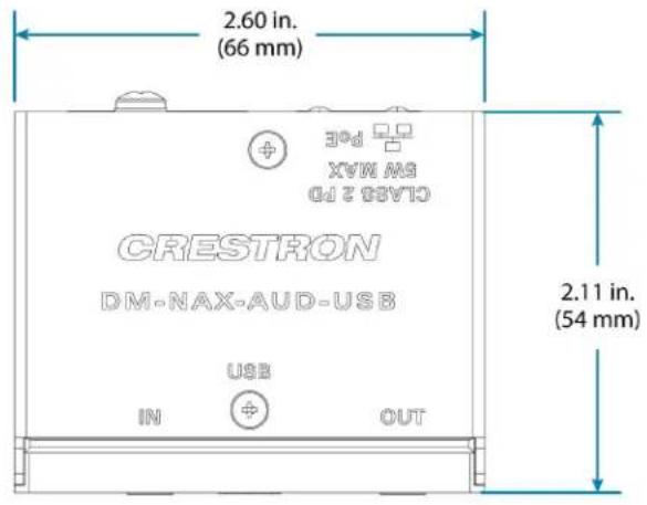
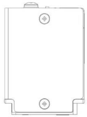
natural_image
Pure technical line drawing of a rectangular component with mounting holes and a central hole (no text or symbols)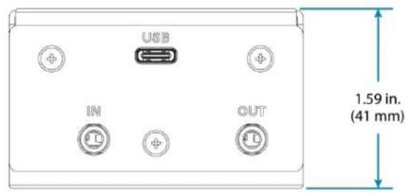
DM-NAX-BTIO-1G Specifications
Product specifications for the DM-NAX-BTIO-1G are provided below.
Specifications
Audio
Input Signal Types Unbalanced stereo analog line-level; Stereo Bluetooth wireless; DM NAX/AES67 audio-over-IP
Output Signal Types Unbalanced stereo analog line-level; DM NAX/AES67 audio-over-IP
Source Compensation ±10.0 dB per input Input Monitoring Source Signal Detect
Frequency Response (at 20 Hz to 20 kHz ±0.5 dB line-level output)
THD+N Line-level: 0.005% @ 1 kHz, max output; Bluetooth: 0.05% @ 1 kHz, max output
S/N Ratio (at line-level output) From line-level input: 108 dB, 20 Hz to 20 kHz, A-weighted; From digital input: 111 dB, 20 Hz to 20 kHz, A-weighted
Balance Control Left/right adjustable
Communications
Ethernet For control and PoE, AoIP, and/or console, 100/1000 Mbps, auto-switching, auto-negotiating, auto-discovery, full/half duplex, DHCP
Bluetooth For audio input, Bluetooth 5.3 sink device, recalls up to seven previously paired devices, persistent or non persistent pairing, exclusive or interrupting connection modes
Connectors
IN (1) 3.5 mm connector, female TRS; Unbalanced line-level audio input; Maximum input level: 2Vrms; Input Impedance: 10 kΩ
OUT (1) 3.5 mm connector, female TRS; Unbalanced line-level audio output; Maximum output level: 2Vrms; Channel separation: 80 dB @ 1 kHz; Output Impedance: 100 Ω
G (1) 6-32 screw; Chassis ground lug
ETHERNET PoE (1) 8-pin RJ-45 connector, female; 100BASE-TX/1000BASE-T Ethernet port
Controls and Indicators
Front Panel Display (1) OLED screen, 128 x 64 dot matrix
Height (active area): 0.43 in. (11 mm)
Width (active area): 0.86 in. (22 mm)
Displays metadata, menus, and volume feedback
Menu (1) Push button
Used to enter the front panel menu and select menu items
Bluetooth (1) Push button
Used to initiate Bluetooth pairing
UP and DOWN Arrows (2) Push buttons
Used to navigate menus and control volume
ETHERNET PoE Left amber LED indicates 1000 Mb link status;
Left green LED indicates 100 Mb link status;
Flashing right amber LED indicates Ethernet activity
SETUP (1) Push button: Used for factory reset procedures;
(1) LED, illuminates red when the button is pressed, flashes red when reset has been initiated
Power
PoE IEEE 802.3af Class O (12.95 W) compliant;
Compatible with IEEE 802.3af compliant Ethernet switch or third-party PoE compliant PSE
Power Consumption 3.5 W
Environmental
Temperature 32° to 95° F (0° to 35° C)
Humidity 10% to 95% RH (noncondensing)
Heat Dissipation 11.95 BTU/hr
Construction
Chassis Metal, black and silver finish, vented sides
Mounting Mountable on the following:
1-gang U.S. electrical box or plaster ring (not included), 3.5 in. (26 mm) electrical box depth recommended;
Rack rail
Dimensions
Height 4.12 in. (105 mm)
Width 1.76 in. (45 mm)
Depth 2.25 in. (57 mm)
Weight
4.8 oz. (136 g)
Regulatory Model: M1845004
IC, FCC Part 15 Class B digital device
Dimension Drawing
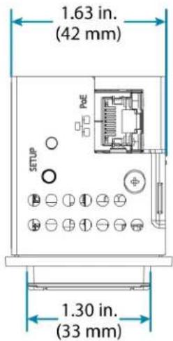
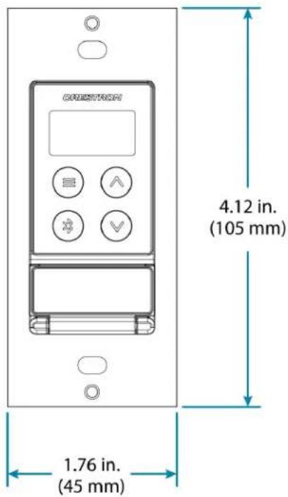
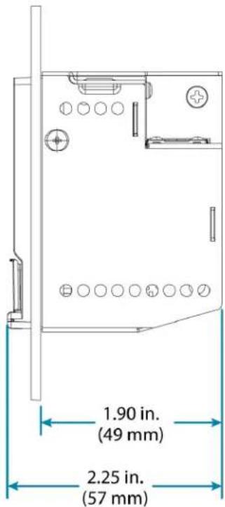
Installation
Refer to the following sections for instructions on how to install the various DM NAX devices.
• DM-NAX-2XLRI-1G
- DM-NAX-8ZSA
- DM-NAX-4ZSA-50
- DM-NAX-4ZSP
- DM-NAX-16AIN
- DM-NAX-AMP-X300
• DM-NAX-AUD-IO
• DM-NAX-AUD-USB
• DM-NAX-BTIO-1G
DM-NAX-2XLRI-1G Installation
Refer to the following sections to install the DM-NAX-2XLRI-1G.
• In the Box on page 65
- Mounting the Device on page 65
- Connect the Device on page 68
- Reset the Device on page 69
In the Box
Qty. Description
1 DM-NAX-2XLRI
Additional Items
2 Screw, 06-32, 3/4 in., Truss Head, Combo (2009211)
Mounting the Device
The DM-NAX-2XLRI-1G can be mounted into a 1-gang electrical box or onto a rack rail.
Mounting into a 1-Gang Electrical Box
NOTES:
- The DM-NAX-2XLRI-1G should only be mounted with a RACO® 3 in. x 2 in. x 2 in. gangable metal switch box with eight 0.5 in. knockouts and plaster ears (catalog ID #420), as it was designed to fit the box dimensions and knockout placements. Alternative metal switch boxes should not be used as they may have different knockout placements, which can lead to issues running the PoE connection to the unit due to cable bend radius restrictions.
- For thermal performance reasons, fully enclosed plastic back boxes should not be used with the DM-NAX-2XLRI-1G. In installations where an enclosed back box is not required, the DM-NAX-2XLRI-1G can be installed into most single gang metal or plastic mud rings.
- Connector boots should not be used on CAT5e (or greater) cables being connected to the DM-NAX-2XLRI-1G to avoid cable bend radius issues.
To mount the wall plate into a 1-gang electrical box, follow the instructions below.
-
Make connections to the rear of the device. For details, refer to Top Panel on page 69.
-
Using a Phillips screwdriver and the two included 6-32 x 3/4 in. truss head screws, attach the wall plate to the electrical box.
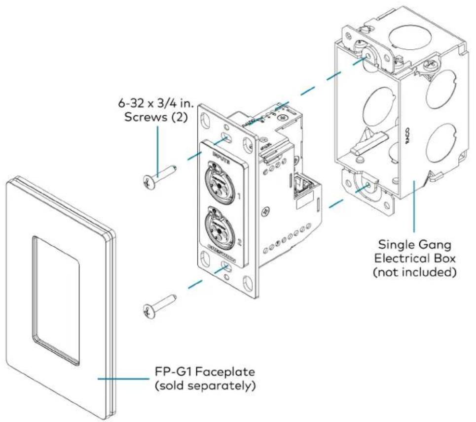
- Using a Phillips screwdriver and two 6-32 x 1/4 in., flat head screws (not included), attach a FP-G1 decorator style faceplate (sold separately) to the wall plate.
Mounting onto a Rack Rail
To mount the wall plate onto a rack rail, follow the instructions below.
-
Position the wall plate horizontally so that the holes in the left or right mounting flange align with the holes in the rack rail.
-
Secure the wall plate to the rack rail using two mounting screws (not included).

Mounting to a Flat Surface
To mount the wall plate to a flat surface, follow the instructions below.
-
Position the wall plate so that the holes in the mounting flange align with the mounting bracket (not included).
-
Connect the wall plate to the mounting bracket using a Phillips screwdriver and two SEMS screws 6-32 x 1/4 in. (not included).
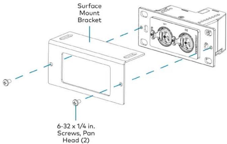
- Secure the mounting bracket to a flat surface using the appropriate mounting screws (not included).
Connect the Device
Make connections to the front and top of the DM-NAX-2XLRI-1G as described below.
Front Panel
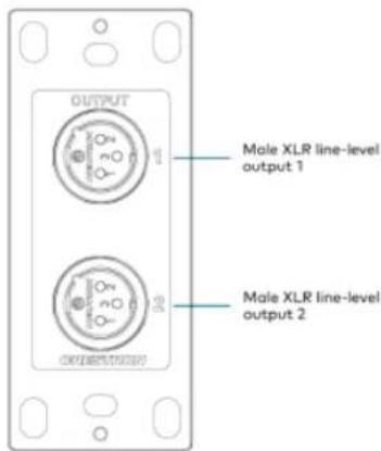
Top Panel
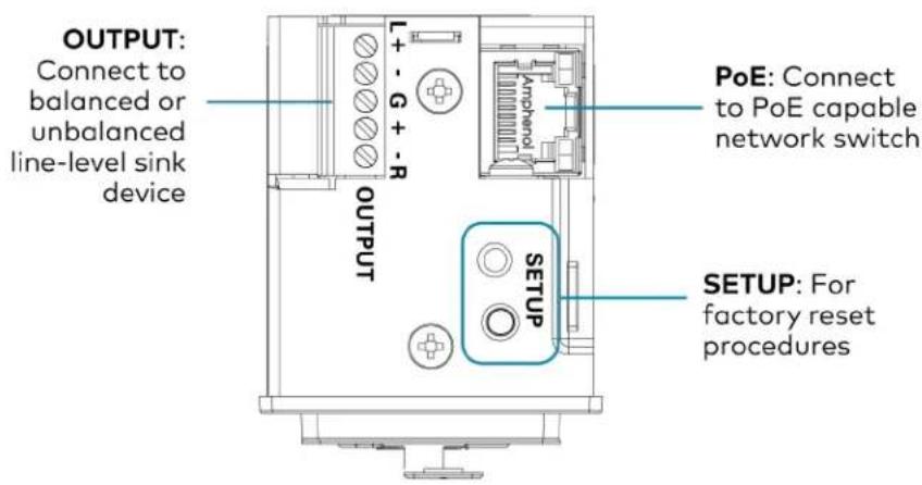
NOTE: PoE is a PoE powered device (PD) port. In order for the port to receive PoE, it must be connected to a PoE compliant Ethernet switch.
Connect a PoE capable network switch to the PoE port.
Connect a balanced or unbalanced line level sink device (such as the MP-WP-2RCAO-1G or MP-WP-2XLRO-1G, sold separately) to the OUTPUT port
Connect XLR sources to the front panel XLR connections.
Reset the Device
A network reset or factory restore may be performed when troubleshooting.
CAUTION: These procedures should only be performed as a last resort to recover an unresponsive device. Both the Network Reset and Factory Restore procedure will clear certain device settings that cannot be recovered once the procedure is complete. Before performing these procedures, please contact Crestron True Blue Support via phone, email or chat as described at www.crestron.com/support.
Network Reset
- Ensure the device is powered on.
- Press and hold the SETUP button for up to 15 seconds until the SETUP LED flashes red.
The device will reboot, and the default network settings will be reset. The device will be reverted to its default hostname, with DHCP enabled, and no static IP set.
Factory Restore
- Turn off the device by disconnecting the power cable from the device.
- Press and hold the SETUP button and then reconnect the power cable while still holding the SETUP button. Continue holding the SETUP button for up to 30 seconds until the SETUP LED flashes.
The device will reboot, and all the factory default settings will be restored, such as audio settings, multicast addressing, etc.
CAUTION: Performing a factory restore will clear all settings from the device configuration.
DM-NAX-8ZSA Installation
Refer to the following sections to install the DM-NAX-8ZSA.
• In the Box on page 71
• Install the Device on page 72
- Connect the Device on page 73
- Apple® AirPlay® Setup on page 77
- Spotify® Connect Setup on page 78
- Observe the LED Indicators on page 78
- Reset the Device on page 80
Front Panel
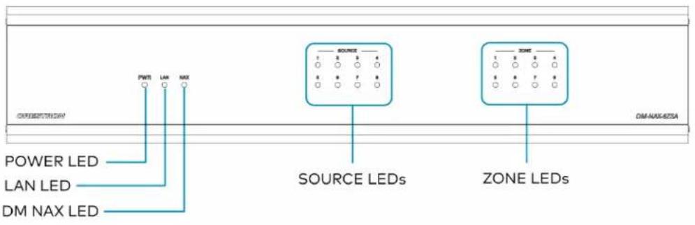
In the Box
Qty. Description
1 DM-NAX-8ZSA
Additional Items
2 Bracket, Rack Ear, 2 RU (2053799)
1 Power Cord, approx. 6.5 ft (2 m) (2014835)
1 Cable, CAT6, RJ45-to-RJ-45, approx. 5 ft (1.5 m) (2036196)
16 Connector, 2-Pin (2012361)
2 Connector, 4-Pin (2003576)
3 Connector, 5-Pin (2003577)
6 Screw, 4B x 1/4 in., Pan Head, Phillips (2007195)
Install the Device
Refer to the Safety Instructions (Doc. 6607) prior to installation.
The device can be placed on a table or installed in a rack.
Place on a Table
Place the device on a table or stack on top of another device.
Rack Installation
This device occupies 2 RU of rack space.
To install the included rack ears:
- Use a #1 Phillips screwdriver to remove the three screws from each side of the front of the device as shown in the illustration.
- Use the screwdriver and the six included 1/4 in. Phillips Pan Head screws to attach the included rack ears to the device.

- Mount the device into the rack using four rack mounting screws (not included).
Rack Mounting Safety Precautions
Elevated Operating Ambient Temperature: If installed in a closed or multi-unit rack assembly, the operating ambient temperature of the rack environment may be greater than room ambient temperature. Therefore, consideration should be given to installing the equipment in an environment compatible with the maximum ambient temperature (Tma) specified by the manufacturer.
Reduced Airflow: Installation of the equipment in a rack should be such that the amount of airflow required for safe operation of the equipment is not compromised.
Mechanical Loading: Mounting of the equipment in the rack should be such that a hazardous condition is not achieved due to uneven mechanical loading.
Circuit Overloading: Consideration should be given to the connection of the equipment to the supply circuit and the effect that overloading of the circuits might have on overcurrent protection and supply wiring. Appropriate consideration of equipment nameplate ratings should be used when addressing this concern.
Reliable Earthing: Reliable earthing of rack-mounted equipment should be maintained. Particular attention should be given to supply connections other than direct connections to the branch circuit (e.g., use of power strips).
Connect the Device
Make the necessary connections as called out in the following illustration. Connect power last.
CAUTION:
- Keep the device unplugged until all of the input, network, output, and speaker wiring is complete.
- Check the speaker cables for shorts and frayed wiring around the SPEAKER OUTPUTS connectors.
NOTE:
- Ensure that the unit is properly grounded by connecting the chassis ground lug to an earth ground (building steel).
- To prevent overheating, do not operate this product in an area that exceeds the environmental temperature range listed in the product specifications.
- Do not bundle power cords together with connection cables. Doing so can result in noise.
Rear Panel

Digital Inputs
Refer to the following illustration when connecting digital audio sources.

NOTE: 2-channel PCM digital audio is the only supported digital input format.
Analog Inputs
Refer to the following illustration when connecting analog audio sources.

Speaker Connections
The speaker outputs can be wired conventionally or bridged together to deliver higher output power.
NOTE: The Line Outputs 1-4 mirror their respective Speaker Outputs 1-4. These outputs can feed another amplifier or an active subwoofer.
Conventional Wiring
Connect speakers to the DM-NAX-8ZSA as shown in the following illustration.
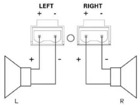
Bridged Wiring
Connect speaker outputs as shown in the following illustration to deliver more power to the speakers (8 ohm speakers only).
NOTE:
- Before wiring the speakers for bridging, ensure that the device is configured for bridging using web UI, Crestron Home™ software, or a Crestron SIMPL program running on a control system.
- Bridging can only be done between a left and a right output within the labeled zone.

Balanced/Unbalanced Audio Output
Refer to the following table and illustration for analog audio output pin assignments and connection information.
| Signal Name Balanced Audio Output Unbalanced Audio Output |
| + L+ L+ Out |
| - L- Open |
| G Shield/ground Open |
| + R+ R+ Out |
| - R- Open |


Apple® AirPlay® Setup
The DM-NAX-8ZSA supports AirPlay 2 and requires iOS 11.4 or later.
AirPlay can be enabled on any of the built-in media players on the DM-NAX-8ZSA.
To stream media from an iOS device to a speaker zone in your distributed audio system:
- Ensure that the iOS device and DM-NAX-8ZSA are on the same network.
- On the DM-NAX-8ZSA, enable AirPlay for the built-in media player you would like to stream to, either using the web UI or programming.
NOTE: If the control/media and Audio-over-IP network traffic is isolated between two network ports on the DM-NAX-8ZSA, AirPlay will use the port specified for the Control/Media traffic.
- On your iOS device:
a. Enable AirPlay
b. From the list of available AirPlay destinations, select the DM-NAX-8ZSA zone you would like to stream to.
The media player will play back audio to the selected zone(s).
Once AirPlay streaming begins, you will be able to control the volume of the streaming DM-NAX-8ZSA speaker zones directly from your iOS device.
NOTE: By default, media players 1 - 8 route the audio signals to their corresponding speaker zones when Airplay streaming begins. If the user has not already specified a destination speaker zone for the media player when streaming begins, the media player will automatically route to its default speaker zone. For example, if a user streams Airplay to media player 3, the audio will be routed to speaker zone 3.
Spotify® Connect Setup
The DM-NAX-8ZSA supports Spotify Connect.
To configure Spotify, use your phone, tablet or computer as a remote control for Spotify. Go to spotify.com/connect to learn how.
Spotify Connect can be enabled on any of the built-in media players on the DM-NAX-8ZSA.
To stream media from a device to a speaker zone in your distributed audio system:
- Ensure that the device and DM-NAX-8ZSA are on the same network.
- On the DM-NAX-8ZSA, enable Spotify Connect for the built-in media player you would like to stream to, either using the web UI or programming.
NOTE: If the control/media and Audio-over-IP network traffic is isolated between two network ports on the DM-NAX-8ZSA, Spotify will use the port specified for the Control/Media traffic.
- On your device:
a. Open the Spotify application or web client.
b. From the list of available Spotify destinations, select the DM-NAX-8ZSA zone you would like to stream to.
The media player will play back audio to the selected zone(s).
Once Spotify Connect streaming begins, you will be able to control the volume of the streaming DM-NAX-8ZSA speaker zones directly from your device.
NOTE: By default, media players 1 - 8 route the audio signals to their corresponding speaker zones when Spotify Connect streaming begins. If the user has not already specified a destination speaker zone when streaming begins, the media player will automatically route to its default speaker zone. For example, if a user streams Spotify Connect to media player 3, the audio will be routed to speaker zone 3.
Observe the LED Indicators
Refer to the following table for information about the LED indicators on the device.
LED Indicator Color Meaning
PWR Amber Power is being applied to the device. The device is booting.
White Device is powered on with audio passing.
Red Device is in standby mode.
LED Indicator Color Meaning
| LAN White The device is powered on and has a valid IP address. | |
| Off Device is not connected to a network or the IP address is invalid. | |
| NAX White AoIP is ready to pass and the unit's PTP clock is synced. | |
| Off No AoIP is passing to or from and/or PTP is not synced. | |
| SOURCE 1-8 White Signal is detected on the specified input/source. | |
| Red There is clipping on an analog input or bitstream audio detected on a digital input. | |
| Off There is no signal detected on the specified input/source. | |
| ZONE 1-8 White There is audio output on the indicated zone. | |
| Red Clipping or a fault is detected on the zone output due to over current, over temperature, or low voltage. | |
| SETUP Solid Red The SETUP button is pressed. | |
| Blinking Red A network reset or factory restore has been initiated via the adjacent SETUP button. | |
Reset the Device
A network reset or factory restore may be performed when troubleshooting.
CAUTION: These procedures should only be performed as a last resort to recover an unresponsive device. Both the Network Reset and Factory Restore procedure will clear certain device settings that cannot be recovered once the procedure is complete. Before performing these procedures, please contact Crestron True Blue Support via phone, email or chat as described at www.crestron.com/support.
Network Reset
- Ensure the device is powered on.
- Press and hold the SETUP button for up to 15 seconds until the SETUP LED flashes red.
The device will reboot, and the default network settings will be reset. The device will be reverted to its default hostname, with DHCP enabled, and no static IP set.
Factory Restore
- Turn off the device by disconnecting the power cable from the device.
- Press and hold the SETUP button and then reconnect the power cable while still holding the SETUP button. Continue holding the SETUP button for up to 30 seconds until the SETUP LED flashes.
The device will reboot, and all the factory default settings will be restored, such as Zone settings, streaming service accounts, multicast addressing, etc.
CAUTION: Performing a factory restore will clear all settings from the device configuration.
DM-NAX-4ZSA-50 Installation
Refer to the following sections to install the DM-NAX-4ZSA-50.
• In the Box on page 81
• Install the Device on page 82
- Connect the Device on page 85
- Spotify® Setup on page 87
- Reset the Device on page 88
- Observe the LED Indicators on page 88
In the Box
Qty. Description
1 DM-NAX-4ZSA-50
Additional Items
1 Power Cord, approx. 6.5 ft (2m) (2001134)
2 Bracket, rack ear, quarter-wide (2057495)
4 Joining plate (2056313)
4 Speaker Connector, 4-Pin (2057001)
4 Screw, 6-32 x 5/16 in., Flat Head, Phillips (2007223)
8 Screw, 8-32 x 5/16 in., Phillips (2056985)
4 Adhesive feet (2002389)
Install the Device
Refer to the Safety Instructions (Doc. 6607) prior to installation.
The device can be placed on a table or installed in a rack.
Place on a Table
Attach the four adhesive feet to the bottom of the device. Place the device on a table or stack on top another device.
Rack Installation
This device occupies 1/2 RU of rack space.
To install the included rack ears:
- Use a #1 Phillips screwdriver and the included 6-32 5/16 in. Phillips screws to attach the included rack ears to the device.

natural_image
Line drawing of a server rack unit with attached panel and connector (no text or symbols)- Mount the device into the rack using four rack mounting screws (not included).
Double Mount
To rack-mount two Crestron 1/2 RU units together:
-
On a flat surface, place the devices upside-down and adjacent to each other.
-
Using a Philips screwdriver and the eight included 8-32 x 5/16 in. screws, gang the devices together with two of the joining plates.
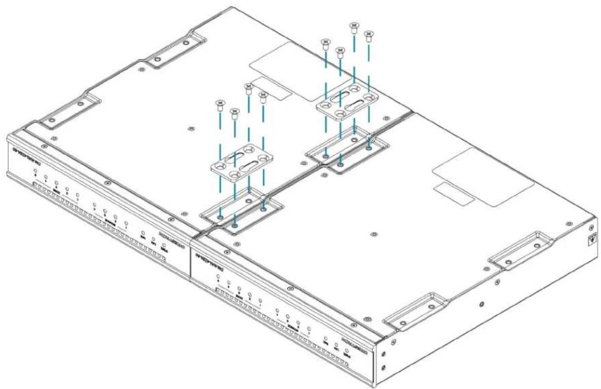
natural_image
Technical line drawing of a server rack with mounting hardware and internal components (no text or symbols)- Turn the device assembly over and, using six 6-32 x 5/16 in. screws, attach the rack ears to each side.

natural_image
Technical line drawing of a server rack with labeled ports and connectors (no text or symbols beyond labels)- Mount the assembly into the rack using four rack mounting screws (not included).
Rack Mounting Safety Precautions
Elevated Operating Ambient Temperature: If installed in a closed or multi-unit rack assembly, the operating ambient temperature of the rack environment may be greater than room ambient temperature. Therefore, consideration should be given to installing the equipment in an environment compatible with the maximum ambient temperature (Tma) specified by the manufacturer.
Reduced Airflow: Installation of the equipment in a rack should be such that the amount of airflow required for safe operation of the equipment is not compromised.
Mechanical Loading: Mounting of the equipment in the rack should be such that a hazardous condition is not achieved due to uneven mechanical loading.
Circuit Overloading: Consideration should be given to the connection of the equipment to the supply circuit and the effect that overloading of the circuits might have on overcurrent protection and supply wiring. Appropriate consideration of equipment nameplate ratings should be used when addressing this concern.
Reliable Earthing: Reliable earthing of rack-mounted equipment should be maintained. Particular attention should be given to supply connections other than direct connections to the branch circuit (e.g., use of power strips).
Connect the Device
Make the necessary connections as called out in the following illustration. Connect power last.
CAUTION:
- Keep the device unplugged until all of the input, network, output, and speaker wiring is complete.
- Check the speaker cables for shorts and frayed wiring around the SPEAKER ZONES connectors.
NOTE:
- Ensure that the unit is properly grounded by connecting the chassis ground lug to an earth ground (building steel).
- To prevent overheating, do not operate this product in an area that exceeds the environmental temperature range listed in the product specifications.
- Do not bundle power cords together with connection cables. Doing so can result in noise.
Rear Panel

Digital Inputs
Refer to the following illustration when connecting digital audio sources.

NOTE: Only 2-channel PCM digital audio is supported at the digital inputs.
Analog Inputs
Refer to the following illustration when connecting analog audio sources.

Speaker Connections
Connect speakers to the DM-NAX-4ZSA-50 as shown in the following illustration.

Spotify® Setup
The DM-NAX-4ZSA-50 supports Spotify.
To configure Spotify, use your phone, tablet or computer as a remote control for Spotify. Go to spotify.com/connect to learn how.
Spotify can be enabled on any of the built-in media players on the DM-NAX-4ZSA-50.
To stream media from a device to a speaker zone in your distributed audio system:
-
Ensure that the device and DM-NAX-4ZSA-50 are on the same network.
-
On the DM-NAX-4ZSA-50, enable Spotify for the built-in media player you would like to stream to, either using the web UI or programming.
NOTE: If the control/media and Audio-over-IP network traffic is isolated between two network ports on the DM-NAX-4ZSA-50, Spotify will use the port specified for the Control/Media traffic.
- On your device:
a. Enable Spotify
b. From the list of available Spotify destinations, select the DM-NAX-4ZSA-50 zone you would like to stream to.
The media player will play back audio to the selected zone(s).
NOTE: By default, media players 1 - 5 route the audio signals to their respectively numbered speaker zones 1 - 5. If the user has not specified the speaker zone when Spotify streaming begins, the media player will automatically route to its default speaker zone. For example, the audio from the media player 3 will be routed to speaker zone 3.
After the Spotify streaming begins, you will be able to control the volume of the streaming DM-NAX-4ZSA-50 speaker zones directly from your device.
Observe the LED Indicators
Refer to the following table for information about the LED indicators on the device.
| LED Indicator Color Meaning | ||
| PWR Amber Power is being applied to the device. The device is booting. | ||
| Ethernet 1 and 2 White The device is powered on and has a valid IP address. | ||
| SOURCE 1-4 White Signal is detected on the specified input/source. | ||
| ZONE 1-4 White There is audio output on the indicated zone. | ||
| ZONE 5 | White There is audio output on the indicated zone. | |
| SETUP | Solid Red | The SETUP button is pressed. |
| Blinking Red | A network reset or factory restore has been initiated via the adjacent SETUP button. | |
Reset the Device
A network reset or factory restore may be performed when troubleshooting.
CAUTION: These procedures should only be performed as a last resort to recover an unresponsive device. Both the Network Reset and Factory Restore procedure will clear certain device settings that cannot be recovered once the procedure is complete. Before performing these procedures, please contact Crestron True Blue Support via phone, email or chat as described at www.crestron.com/support.
Network Reset
- Ensure the device is powered on.
- Press and hold the SETUP button for up to 15 seconds until the SETUP LED flashes red.
The device will reboot, and the default network settings will be reset. The device will be reverted to its default hostname, with DHCP enabled, and no static IP set.
Factory Restore
- Turn off the device by disconnecting the power cable from the device.
- Press and hold the SETUP button and then reconnect the power cable while still holding the SETUP button. Continue holding the SETUP button for up to 30 seconds until the SETUP LED flashes.
The device will reboot, and all the factory default settings will be restored, such as Zone settings, streaming service accounts, multicast addressing, etc.
CAUTION: Performing a factory restore will clear all settings from the device configuration.
DM-NAX-4ZSP Installation
Refer to the following sections to install the DM-NAX-4ZSP.
• In the Box on page 90
• Install the Device on page 91
- Connect the Device on page 92
- Observe the LED Indicators on page 96
• Apple® AirPlay® Setup on page 94
- Spotify® Connect Setup on page 95
- Reset the Device on page 97
Front Panel

In the Box
Qty. Description
1 DM-NAX-4ZSP
Additional Items
2 Bracket, Rack Ear, 2 RU (2032122)
1 Power Cord, approx. 6.5 ft (2 m) (2001134)
2 Connector, 4-Pin (2003576)
3 Connector, 5-Pin (2003577)
4 Feet, Adhesive (2002389)
Install the Device
Refer to the Safety Instructions (Doc. 6607) prior to installation.
The device can be placed on a table or installed in a rack.
Place on a Flat Surface
Place the device on a flat surface such as a table.
Install in a Rack
This device occupies 1U of rack space.
- Use a Phillips screwdriver (not included) to remove the three screws from each side of the device as shown in the illustration.
- Use the screwdriver and the six screws (removed earlier) to attach the included rack ears to the device.

- Mount the device into the rack using four rack mounting screws (not included).
Rack Mounting Safety Precautions
Elevated Operating Ambient Temperature: If installed in a closed or multi-unit rack assembly, the operating ambient temperature of the rack environment may be greater than the room ambient temperature. Therefore, consideration should be given to installing the equipment in an environment compatible with the maximum ambient temperature (Tma) specified by the manufacturer.
Reduced Airflow: Installation of the equipment in a rack should be such that the amount of airflow required for safe operation of the equipment is not compromised.
Mechanical Loading: Mounting of the equipment in the rack should be such that a hazardous condition is not achieved due to uneven mechanical loading.
Circuit Overloading: Consideration should be given to the connection of the equipment to the supply circuit and the effect that overloading of the circuits might have on overcurrent protection and supply wiring. Appropriate consideration of equipment nameplate ratings should be used when addressing this concern.
Reliable Earthing: Reliable earthing of rack-mounted equipment should be maintained. Particular attention should be given to supply connections other than direct connections to the branch circuit (e.g., use of power strips).
Connect the Device
Make the necessary connections as called out in the following illustration. Connect power last.
CAUTION:
- Keep the device unplugged until all of the input, network, output, and speaker wiring is complete.
NOTES:
- Ensure that the unit is properly grounded by connecting the chassis ground lug to an earth ground (building steel).
- To prevent overheating, do not operate this product in an area that exceeds the environmental temperature range of 32^ to 104^ ( 0^ to 40^ ).
- Do not bundle power cords together with connection cables. Doing so can result in noise.
Rear Panel

Digital Inputs
Refer to the following illustration when connecting digital audio sources.

NOTE: 2-channel PCM digital audio is the only supported digital input format.
Analog Inputs
Refer to the following illustration when connecting analog audio sources.

Balanced/Unbalanced Audio Output
Refer to the following table and illustration for analog audio output pin assignments and connection information.
Signal Name Balanced Audio Output Unbalanced Audio Output
| + L+ L+ |
| - L- L Shield |
| G Shield/ground G, L Shield, and R Shield |
| + R+ R+ |
| - R- R Shield |
Balanced Input

Unbalanced Input

Apple® AirPlay® Setup
The DM-NAX-4ZSP supports AirPlay 2 and requires iOS 11.4 or later.
AirPlay can be enabled on any of the built-in media players on the DM-NAX-4ZSP.
To stream media from an iOS device to an output zone in your distributed audio system:
- Ensure that the iOS device and DM-NAX-4ZSP are on the same network.
- On the DM-NAX-4ZSP, enable AirPlay for the built-in media player you would like to stream to, either using the web UI or programming.
NOTE: If the control/media and Audio-over-IP network traffic is isolated between two network ports on the DM-NAX-4ZSP, AirPlay will use the port specified for the Control/Media traffic.
- On your iOS device:
a. Enable AirPlay
b. From the list of available AirPlay destinations, select the DM-NAX-4ZSP zone you would like to stream to.
The media player will play back audio to the selected zone(s).
Once AirPlay streaming begins, you will be able to control the volume of the streaming DM-NAX-4ZSP output zones directly from your iOS device.
NOTE: By default, media players 1 - 4 route the audio signals to their corresponding output zones when Airplay streaming begins. If the user has not already specified a destination output zone for the media player when streaming begins, the media player will automatically route to its default output zone. For example, if a user streams Airplay to media player 3, the audio will be routed to output zone 3.
Spotify® Connect Setup
The DM-NAX-4ZSP supports Spotify Connect.
To configure Spotify, use your phone, tablet or computer as a remote control for Spotify. Go to spotify.com/connect to learn how.
Spotify Connect can be enabled on any of the built-in media players on the DM-NAX-4ZSP.
To stream media from a device to a output zone in your distributed audio system:
- Ensure that the device and DM-NAX-4ZSP are on the same network.
- On the DM-NAX-4ZSP, enable Spotify Connect for the built-in media player you would like to stream to, either using the web UI or programming.
NOTE: If the control/media and Audio-over-IP network traffic is isolated between two network ports on the DM-NAX-4ZSP, Spotify will use the port specified for the Control/Media traffic.
- On your device:
a. Open the Spotify application or web client.
b. From the list of available Spotify destinations, select the DM-NAX-4ZSP zone you would like to stream to.
The media player will play back audio to the selected zone(s).
Once Spotify Connect streaming begins, you will be able to control the volume of the streaming DM-NAX-4ZSP output zones directly from your device.
NOTE: By default, media players 1 - 4 route the audio signals to their corresponding output zones when Spotify Connect streaming begins. If the user has not already specified a destination output zone when streaming begins, the media player will automatically route to its default output zone. For example, if a user streams Spotify Connect to media player 3, the audio will be routed to output zone 3.
Observe the LED Indicators
Refer to the following table for information about the LED indicators on the device.
| LED Indicator Color Meaning | ||
| PWR White Device is powered on with audio passing. | ||
| Red Device is in standby mode. | ||
| Off Device is not powered on. | ||
| LAN White The device is powered on and has a valid IP address. | ||
| Off Device is not connected to a network or the IP address is invalid. | ||
| NAX White AoIP is ready to pass and the unit's PTP clock is synced. | ||
| Off No AoIP is passing to or from the unit and/or PTP is not synced. | ||
| SOURCE 1-8 White Signal is detected on the specified input/source. | ||
| Red There is clipping on an analog input or bitstream audio detected on a digital input. | ||
| Off There is no signal detected on the specified input/source. | ||
| ZONE 1-4 White There is audio output on the indicated zone. | ||
| Red Clipping is detected on the output audio. | ||
| SETUP | Solid Red | The SETUP button is pressed. |
| Blinking Red | A network reset or factory restore has been initiated via the adjacent SETUP button. | |
Reset the Device
A network reset or factory restore may be performed when troubleshooting.
CAUTION: These procedures should only be performed as a last resort to recover an unresponsive device. Both the Network Reset and Factory Restore procedure will clear certain device settings that cannot be recovered once the procedure is complete. Before performing these procedures, please contact Crestron True Blue Support via phone, email or chat as described at www.crestron.com/support.
Network Reset
- Ensure the device is powered on.
- Press and hold the SETUP button for up to 15 seconds until the SETUP LED flashes red.
The device will reboot, and the default network settings will be reset. The device will be reverted to its default hostname, with DHCP enabled, and no static IP set.
Factory Restore
- Turn off the device by disconnecting the power cable from the device.
- Press and hold the SETUP button and then reconnect the power cable while still holding the SETUP button. Continue holding the SETUP button for up to 30 seconds until the SETUP LED flashes.
The device will reboot, and all the factory default settings will be restored, such as Zone settings, streaming service accounts, multicast addressing, etc.
CAUTION: Performing a factory restore will clear all settings from the device configuration.
DM-NAX-16AIN Installation
Refer to the following sections to install the DM-NAX-16AIN.
• In the Box on page 98
• Install the Device on page 99
- Connect the Device on page 101
- Observe the LED Indicators on page 103
- Reset the Device on page 104
Front Panel

In the Box
Qty. Description
1 DM-NAX-16AIN
Additional Items
2 Bracket, Rack Ear, 1U (2032122)
4 Connector, 5-Pin (2003577)
1 Power Cord, 6 ft 7 in. (2 m) (2001134)
Install the Device
Refer to the Safety Instructions (Doc. 6607) prior to installation.
The device can be placed on a flat surface or installed in a rack.
Place on a Flat Surface
Place the device on a flat surface such as a table.
Install in a Rack
This device occupies 1U of rack space.
- Use a Phillips screwdriver (not included) to remove the three screws from each side of the device as shown in the illustration.
- Use the screwdriver and the six screws (removed earlier) to attach the included rack ears to the device.

- Mount the device into the rack using four rack mounting screws (not included).
Rack Mounting Safety Precautions
Elevated Operating Ambient Temperature: If installed in a closed or multi-unit rack assembly, the operating ambient temperature of the rack environment may be greater than the room ambient temperature. Therefore, consideration should be given to installing the equipment in an environment compatible with the maximum ambient temperature (Tma) specified by the manufacturer.
Reduced Airflow: Installation of the equipment in a rack should be such that the amount of airflow required for safe operation of the equipment is not compromised.
Mechanical Loading: Mounting of the equipment in the rack should be such that a hazardous condition is not achieved due to uneven mechanical loading.
Circuit Overloading: Consideration should be given to the connection of the equipment to the supply circuit and the effect that overloading of the circuits might have on overcurrent protection and supply wiring. Appropriate consideration of equipment nameplate ratings should be used when addressing this concern.
Reliable Earthing: Reliable earthing of rack-mounted equipment should be maintained. Particular attention should be given to supply connections other than direct connections to the branch circuit (e.g., use of power strips).
Connect the Device
Make the necessary connections as called out in the following illustration. Connect power last.
CAUTION:
- Keep the device unplugged until all of the input wiring is complete.
- Check the connections for shorts and frayed wiring at all the input connectors.
NOTES:
- Ensure that the unit is properly grounded by connecting the chassis ground lug to an earth ground (building steel).
- To prevent overheating, do not operate this product in an area that exceeds the environmental temperature range of 32^ to 104^ ( 0^ to 40^ ).
- Do not bundle power cords together with connection cables. Doing so can result in noise.
Rear Panel

Digital Inputs
Refer to the following illustration when connecting digital audio sources.

NOTE: 2-channel PCM digital audio is the only supported digital input format.
Analog Inputs
Refer to the following illustration when connecting analog audio sources.

Balanced/Unbalanced Audio Input
Refer to the following table and illustration for analog audio input pin assignments and connection information.
| Signal Name Balanced Audio Input Unbalanced Audio Input |
| + L+ L+ |
| - L- Open |
| G Shield/ground Open |
| + R+ R+ |
| - R- Open |


Observe the LED Indicators
Refer to the following table for information about the LED indicators on the device.
| LED Indicator Color Meaning | ||
| PWR | Amber | Power is being applied to the device. The device is booting. |
| White | Device is powered on with audio passing. | |
| Red | Device is in standby mode. | |
| LAN | White | The device is powered on and has a valid IP address. |
| Off | Device is not connected to a network or the IP address is invalid. | |
| NAX | White | AoIP is ready to pass and the unit's PTP clock is synced. |
| Off | No AoIP is passing to or from and/or PTP is not synced. | |
| SOURCE 1-16 | White | Signal is detected on the specified input/source. |
| Red | There is clipping on an analog input or bitstream audio detected on a digital input. | |
| Off | There is no signal detected on the specified input/source. | |
LED Indicator Color Meaning
SETUP Solid Red The SETUP button is pressed.
Blinking Red A network reset or factory restore has been initiated via the adjacent SETUP button.
Reset the Device
A network reset or factory restore may be performed when troubleshooting.
CAUTION: These procedures should only be performed as a last resort to recover an unresponsive device. Both the Network Reset and Factory Restore procedure will clear certain device settings that cannot be recovered once the procedure is complete. Before performing these procedures, please contact Crestron True Blue Support via phone, email or chat as described at www.crestron.com/support.
Network Reset
- Ensure the device is powered on.
- Press and hold the SETUP button for up to 15 seconds until the SETUP LED flashes red.
The device will reboot, and the default network settings will be reset. The device will be reverted to its default hostname, with DHCP enabled, and no static IP set.
Factory Restore
- Turn off the device by disconnecting the power cable from the device.
- Press and hold the SETUP button and then reconnect the power cable while still holding the SETUP button. Continue holding the SETUP button for up to 30 seconds until the SETUP LED flashes.
The device will reboot, and all the factory default settings will be restored, such as Zone settings, names multicast addressing, etc.
CAUTION: Performing a factory restore will clear all settings from the device configuration.
DM-NAX-AMP-X300 Installation
Refer to the following sections to install the DM-NAX-AMP-X300.
• In the Box on page 106
• Install the Device on page 107
- Connect the Device on page 111
- Speaker Mode Selection Switch on page 111
• Lo-Z Modes Selection Switch on page 112
- Observe the LED Indicators on page 112
- Reset the Device on page 113
In the Box
Qty. Description
1 DM-NAX-AMP-X300
Additional Items
4 Plate, Joining (2055198)
8 Screw, 8-32 x 5/16 in., Flat Head, Philips, Black (2055195)
4 Screw, 6-32 x 3/8 in., Undercut Head, Philips (2055196)
4 Foot, Adhesive, Black (2055200)
2 Rack Ear Assembly, 1U, Quarter-width (2055197), includes Bracket, Rack Ear, 1U (2055199)
2 Connector, Speaker (2055026)
8 Connector, input, output (2055207)
1 Connector, 2-Pin (2003574)
1 Power cord (2055205)
Install the Device
The DM-NAX-AMP-X300 can be placed or mounted on a flat surface or installed in a rack.
Place on a Flat Surface
Place the DM-NAX-AMP-X300 on a table or other flat surface. Attach the four adhesive feet as shown below.

Mount on a Flat Surface
To mount the DM-NAX-AMP-X300 on a flat surface:
- Use the eight included 8-32 x 5/16 in. screws to attach the four joining plates to the underside of the device as shown in the illustration.

natural_image
Line drawing of a server rack with mounting hardware and indicator lights (no text or symbols)- Position the device as desired and use screws (not included) and anchors (not included) to mount it.

natural_image
Technical line drawing of a mechanical assembly with dashed alignment lines (no text or symbols)Rack Installation
The DM-NAX-AMP-X300 occupies one half of 1RU of rack space. Two DM-NAX-AMP-X300 units can be placed together and only occupy 1 RU of rack space.
Single Amp
To install the included rack ears on a single DM-NAX-AMP-X300:
- Use a #1 Philips screwdriver to remove the three screws from each side of the front of the device.
- Use the screwdriver and the four included 1/4 in. Philips Pan Head screws to attach the included rack ears to the device.
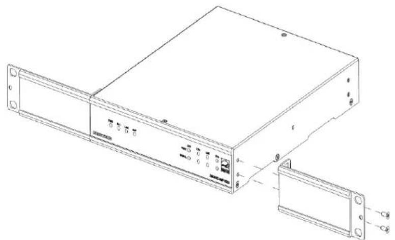
natural_image
Technical line drawing of a server rack with ports and connectors (no text or symbols)- Mount the device into the rack using four rack mounting screws (not included).
Double Amp
To rack-mount two DM-NAX-AMP-X300 units together:
-
On a flat surface, place the amplifiers upside-down and adjacent to each other.
-
Using a Philips screwdriver and the eight included 8-32 x 5/16 in. screws, gang the amplifiers together with two of the joining plates.

natural_image
Line drawing of a server rack with multiple ports and mounting hardware (no text or symbols)- Use a wrench or M5.5 socket to remove the nuts from the rack ears.

natural_image
Technical line drawing of a metal bracket with mounting holes and bolted joints (no text or symbols)- Turn the amplifier assembly over and, using six 6-32 x 3/8 in. screws, attach the rack ears to each side.

natural_image
Technical line drawing of a server rack with two panels and a separate connector (no text or symbols)- Mount the assembly into the rack using four rack mounting screws (not included).
NOTE: Observe the following rack mount installation guidelines.
Elevated Operating Ambient Temperature: If installed in a closed or multi-unit rack assembly, the operating ambient temperature of the rack environment may be greater than room ambient
temperature. Therefore, consideration should be given to installing the equipment in an environment compatible with the maximum ambient temperature (Tma) specified by the manufacturer.
Reduced Airflow: Installation of the equipment in a rack should be such that the amount of airflow required for safe operation of the equipment is not compromised.
Mechanical Loading: Mounting of the equipment in the rack should be such that a hazardous condition is not achieved due to uneven mechanical loading.
Circuit Overloading: Consideration should be given to the connection of the equipment to the supply circuit and the effect that overloading of the circuits might have on overcurrent protection and supply wiring. Appropriate consideration of equipment nameplate ratings should be used when addressing this concern.
Reliable Earthing: Reliable earthing of rack-mounted equipment should be maintained. Particular attention should be given to supply connections other than direct connections to the branch circuit (e.g., use of power strips).
WARNING: To prevent bodily injury when mounting or servicing the unit in a rack:
- When mounting the unit into a partially filled rack, load the rack from the bottom to the top with the heaviest component at the bottom of the rack.
- If the rack is provided with stabilizing devices, install the stabilizers before mounting or servicing the unit in the rack.
Connect the Device
Make the necessary connections as called out in the following illustration. For details on wiring, refer to Output Wiring Options on page 114.
CAUTION:
- Keep the device unplugged until all of the input, network, output, and speaker wiring is complete.
- Check the speaker cables for shorts and frayed wiring around the speaker output connectors.
NOTES:
- Ensure that the unit is properly grounded by connecting the chassis ground lug to an earth ground (building steel).
- To prevent overheating, do not operate this product in an area that exceeds the environmental temperature range listed in the table of specifications.
- Ensure that both the Ethernet ports are not connected to the same network or switch.

Speaker Mode Selection Switch
The DM-NAX-AMP-X300 can be configured to work with 4 Ω and 8 Ω (low impedance or Lo-Z) loads or a distributed audio (high impedance or Hi-Z) 70/100V system.
- Lo-Z: Set the switch to LoZ to use the amplifier with 4 Ω or 8 Ω low impedance loudspeakers.
- 70V: Set the switch to 70V to use the amplifier in a 70V distributed audio system.
- 100V: Set the switch to 100V to use the amplifier in a 100V distributed audio system.
Lo-Z Modes Selection Switch
When operating in Lo-Z mode, the DM-NAX-AMP-X300 outputs can operate in stereo, as summed outputs or as bridged outputs. Set the Lo-Z Modes selection switch to the desired setting and connect the outputs as required.
Select stereo, summed, or bridged operation:
- STEREO: The input signal received on each channel is sent to its respective output for use in applications where left and right channel separation is required.
- SUM: The input signals sent to a channel pair (1 + 2 or 3 + 4) are summed and sent to their respective individual outputs.
• BRIDGE: The input signals sent to a channel pair (1 + 2 or 3 + 4) are summed and sent to a bridged output (1 + 2 or 3 + 4) for use in high power applications.
NOTE:
- If the Rear Panel Lockout indicator is enabled, the web user interface settings will override the both switch selections.
Observe the LED Indicators

The LEDs provide the following information:
| LED Indicator Color Meaning | ||
| PWR | White The device is operating normally. | |
| Amber The device is booting. | ||
| Red The device has entered Standby (Power Saver) mode. | ||
| Hi-Z White | Hi-Z mode is enabled (70V or 100V);Channels 1-2 and 3-4 are bridged and set to 70V or 100V operation. | |
| LAN White The device has a valid IP address. | ||
| AoIP White The device has is handling an AoIP stream. | ||
| FAULT Red There | is a fault on | the indicated channel. |
| SIGNAL | White An audio signal is present on the indicated speaker channel. | |
| Red Clipping | is detecting on the indicated speaker channel. | |
Reset the Device
A network reset or factory restore may be performed when troubleshooting.
CAUTION: These procedures should only be performed as a last resort to recover an unresponsive device. Both the Network Reset and Factory Restore procedure will clear certain device settings that cannot be recovered once the procedure is complete. Before performing these procedures, please contact Crestron True Blue Support via phone, email or chat as described at www.crestron.com/support.
Network Reset
- Ensure the device is powered on.
- Press and hold the SETUP button for up to 15 seconds until the SETUP LED flashes red.
Factory Restore
To restore all settings to factory default, perform the following steps:
- Turn off the device by disconnecting the power cable from the device.
- Press and hold the SETUP button and then reconnect the power cable while still holding the SETUP button. Continue holding the SETUP button for up to 30 seconds until the SETUP LED flashes.
The device will reboot, and all the factory default settings will be restored, such as Zone settings, names multicast addressing, etc.
CAUTION: Performing a factory restore will clear all settings from the device configuration.
Output Wiring Options
The DM-NAX-AMP-X300 can be configured for low impedance (LoZ) stereo operation over two or four channels and high impedance (70 V or 100 V) operation over two channels. Refer to the following diagrams for details.
Four Channels up to 75 W (Lo-Z)
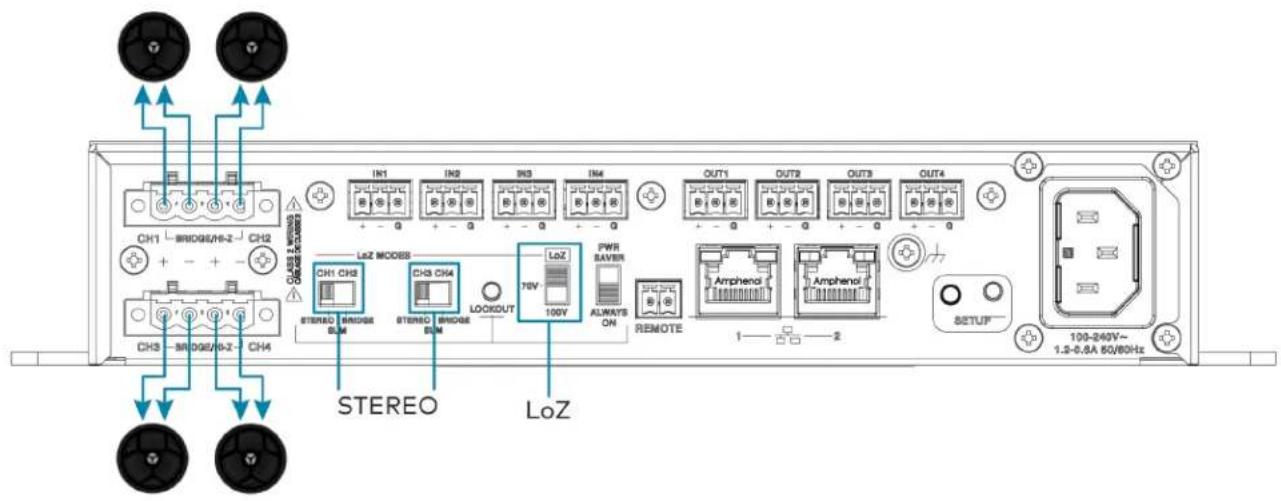
Two Channels up to 150 W (Lo-Z)
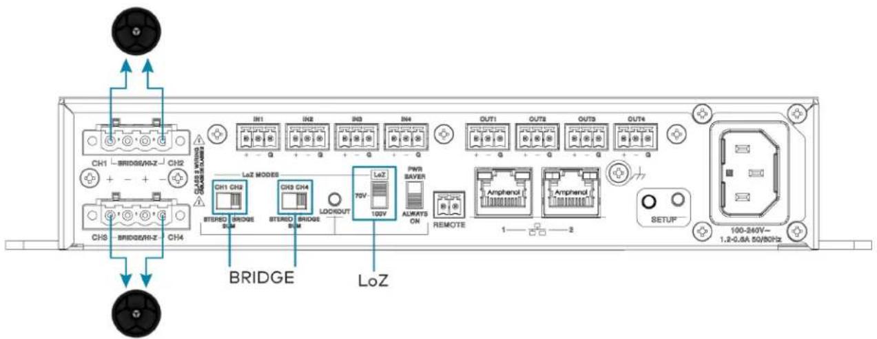
Two Channels up to 75 W and One Channel up to 150 W (Lo-Z)

One Channel up to 300 W (Lo-Z)

Two Runs up to 150 W (Hi-Z)

One Run up to 300 W (Hi-Z)
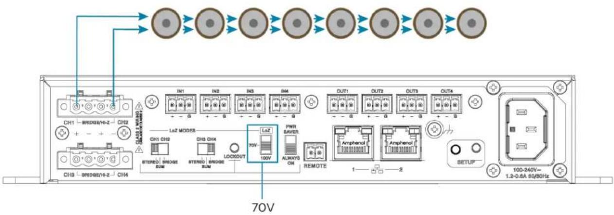
DM-NAX-AUD-IO Installation
Refer to the following sections to install the DM-NAX-AUD-IO.
• In the Box on page 117
- Mount the Device on page 117
- Connect the Device on page 121
- Reset the Device on page 123
In the Box
Qty. Description
1 DM-NAX-AUD-IO
Additional Items
1 Single gang electrical box adapter bracket, galvanized metal (2059673)
2 Surface mount bracket, aluminum (2059674)
2 Connector, 5-pin (2003577)
2 Screws, M3 x 6 mm, Flat Head, Phillips (2062526)
4 Screws, M3 x 0.5 x 6 mm, Pan Head, Phillips (2058870)
1 Polycarbonate front panel label (4536923)
Mount the Device
The DM-NAX-AUD-IO can be mounted under a table, into a 1-gang electrical box, or onto a rack rail.
Mounting under a Table
To mount the device under a table:
- Using a Phillips screwdriver, remove the four flat head screws from the left and right panels of the device.
-
Align the two included right angle surface mount brackets with the left and right panels of the device. For mounting under a table, keep the flanged surface of the brackets flush with the top panel of the device. For mounting to a surface, keep the flanged surface of the brackets flush with the bottom panel of the device.
-
Using a Phillips screwdriver and the four included M3 pan head screws, attach the mounting brackets to the device.

- Secure the device to a surface or under a table using the appropriate mounting screws (not included).
Mounting into a 1-Gang Electrical Box
NOTES:
- The DM-NAX-AUD-IO should only be mounted with a RACO® 3 in. x 2 in. x 2 in. gangable metal switch box with eight 0.5 in. knockouts and plaster ears (catalog ID #420), as it was designed to fit the box dimensions and knockout placements. Alternative metal switch boxes should not be used as they may have different knockout placements, which can lead to issues running the PoE connection to the unit due to cable bend radius restrictions.
- For thermal performance reasons, fully enclosed plastic back boxes should not be used with the DM-NAX-AUD-IO. In installations where an enclosed back box is not required, the DM-NAX-AUD-IO can be installed into most single gang metal or plastic mud rings.
- Connector boots should not be used on CAT5e (or greater) cables being connected to the DM-NAX-AUD-IO to avoid cable bend radius issues.
To mount the device into a 1-gang electrical box:
- Using a Phillips screwdriver, remove the two screws from the top and bottom panels nearer to the front panel of the device.
-
Align the included polycarbonate front panel label with the front panel of the device so the holes in the label line up with the 5-pin connectors.
-
Using a Phillips screwdriver and the included M3 flat head screws, secure the included single gang electrical box adapter bracket to the top and bottom panels of the device.

-
Using a Phillips screwdriver and two 6-32 x 3/4 in., truss head screws (not included), attach the wall plate adapter bracket to the electrical box.
-
Using a Phillips screwdriver and two 6-32 x 1/4 in., flat head screws (not included), attach a FP-G1 decorator style faceplate (sold separately) to the wall plate.
Mounting onto a Rack Rail
To mount the device onto a rack rail:
-
Using a Phillips screwdriver, remove the two screws from the top and bottom panels nearer to the front panel of the device.
-
Using a Phillips screwdriver and the included M3 flat head screws, secure the included single gang electrical box adapter bracket to the top and bottom panels of the device.

-
Position the wall plate horizontally so that the holes in the left or right mounting flange align with the holes in the rack rail.
-
Secure the wall plate to the rack rail using two mounting screws (not included).

Connect the Device
Make connections to the front and rear panels of the DM-NAX-AUD-IO as described below.
Rear Panel
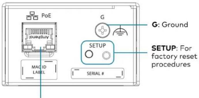
PoE: Connect to PoE capable network switch
NOTE: PoE is a PoE powered device (PD) port. In order for the port to receive PoE, it must be connected to a PoE compliant Ethernet switch.
Connect a PoE capable network switch to the PoE port.
Front Panel
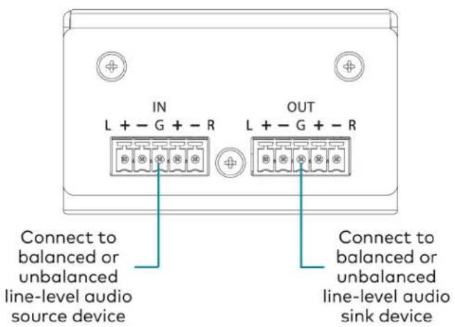
Connect a balanced or unbalanced line-level audio source signal to the INPUTS 5-pin terminal block.
Connect a balanced or unbalanced line-level audio sink device to the OUTPUTS 5-pin terminal block.
Balanced/Unbalanced Audio Input
Refer to the following table and illustration for analog audio input pin assignments and connection information.
| Signal Name Balanced Audio Input Unbalanced Audio Input |
| + L+ L+ |
| - L- Open |
| G Shield/ground Open |
| + R+ R+ |
| - R- Open |


Reset the Device
A network reset or factory restore may be performed when troubleshooting.
CAUTION: These procedures should only be performed as a last resort to recover an unresponsive device. Both the Network Reset and Factory Restore procedure will clear certain device settings that cannot be recovered once the procedure is complete. Before performing these procedures, please contact Crestron True Blue Support via phone, email or chat as described at www.crestron.com/support.
Network Reset
- Ensure the device is powered on.
- Press and hold the SETUP button for up to 15 seconds until the SETUP LED flashes red.
The device will reboot, and the default network settings will be reset. The device will be reverted to its default hostname, with DHCP enabled, and no static IP set.
Factory Restore
- Turn off the device by disconnecting the power cable from the device.
- Press and hold the SETUP button and then reconnect the power cable while still holding the SETUP button. Continue holding the SETUP button for up to 30 seconds until the SETUP LED flashes.
The device will reboot, and all the factory default settings will be restored, such as audio settings, multicast addressing, etc.
CAUTION: Performing a factory restore will clear all settings from the device configuration.
DM-NAX-AUD-USB Installation
Refer to the following sections to install the DM-NAX-AUD-USB.
• In the Box on page 125
- Mount the Device on page 125
- Connect the Device on page 129
- Reset the Device on page 131
In the Box
Qty. Description
1 DM-NAX-AUD-USB
Additional Items
1 Single gang electrical box adapter bracket, galvanized metal (2059673)
2 Surface mount bracket, aluminum (2059674)
2 Screws, M3 x 6 mm, Flat Head, Phillips (2062526)
4 Screws, M3 x 0.5 x 6 mm, Pan Head, Phillips (2058870)
1 Polycarbonate front panel label (4536924)
Mount the Device
The DM-NAX-AUD-USB can be mounted under a table, into a 1-gang electrical box, or onto a rack rail.
Mounting under a Table
To mount the device under a table:
- Using a Phillips screwdriver, remove the four flat head screws from the left and right panels of the device.
-
Align the two included right angle surface mount brackets with the left and right panels of the device. For mounting under a table, keep the flanged surface of the brackets flush with the top panel of the device. For mounting to a surface, keep the flanged surface of the brackets flush with the bottom panel of the device.
-
Using a Phillips screwdriver and the four included M3 pan head screws, attach the mounting brackets to the device.

- Secure the device to a surface or under a table using the appropriate mounting screws (not included).
Mounting into a 1-Gang Electrical Box
NOTES:
- The DM-NAX-AUD-USB should only be mounted with a RACO® 3 in. x 2 in. x 2 in. gangable metal switch box with eight 0.5 in. knockouts and plaster ears (catalog ID #420), as it was designed to fit the box dimensions and knockout placements. Alternative metal switch boxes should not be used as they may have different knockout placements, which can lead to issues running the PoE connection to the unit due to cable bend radius restrictions.
- For thermal performance reasons, fully enclosed plastic back boxes should not be used with the DM-NAX-AUD-USB. In installations where an enclosed back box is not required, the DM-NAX-AUD-USB can be installed into most single gang metal or plastic mud rings.
- Connector boots should not be used on CAT5e (or greater) cables being connected to the DM-NAX-AUD-USB to avoid cable bend radius issues.
To mount the device into a 1-gang electrical box:
-
Using a Phillips screwdriver, remove the two screws from the top and bottom panels nearer to the front panel of the device.
-
Align the included polycarbonate front panel label with the front panel of the device so the holes in the label line up with the 5-pin connectors.
-
Using a Phillips screwdriver and the included M3 flat head screws, secure the included single gang electrical box adapter bracket to the top and bottom panels of the device.
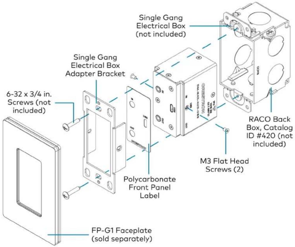
-
Using a Phillips screwdriver and two 6-32 x 3/4 in., truss head screws (not included), attach the wall plate adapter bracket to the electrical box.
-
Using a Phillips screwdriver and two 6-32 x 1/4 in., flat head screws (not included), attach a FP-G1 decorator style faceplate (sold separately) to the wall plate.
Mounting onto a Rack Rail
To mount the device onto a rack rail:
-
Using a Phillips screwdriver, remove the two screws from the top and bottom panels nearer to the front panel of the device.
-
Using a Phillips screwdriver and the included M3 flat head screws, secure the included single gang electrical box adapter bracket to the top and bottom panels of the device.
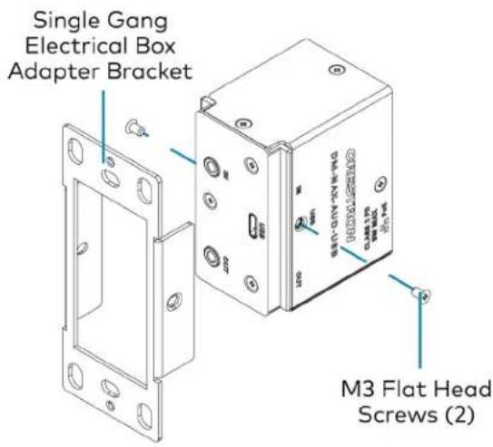
-
Position the wall plate horizontally so that the holes in the left or right mounting flange align with the holes in the rack rail.
-
Secure the wall plate to the rack rail using two mounting screws (not included).
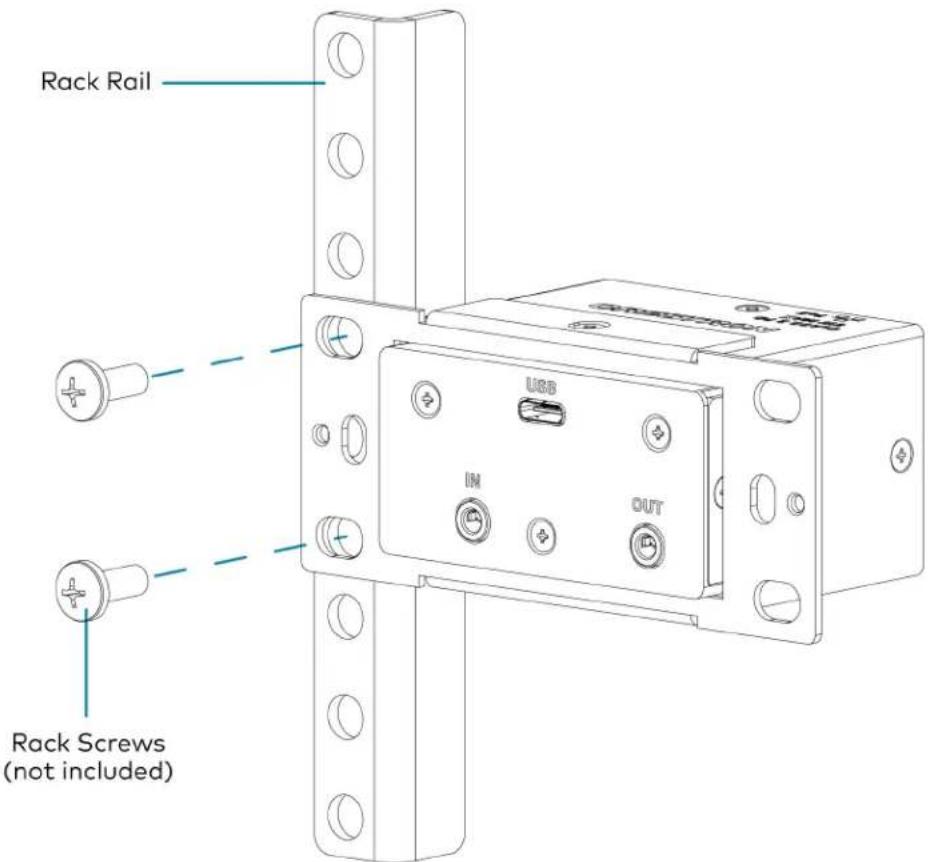
Connect the Device
Make connections to the front and rear panels of the DM-NAX-AUD-USB as described below.
Rear Panel

NOTE: PoE is a PoE powered device (PD) port. In order for the port to receive PoE, it must be connected to a PoE compliant Ethernet switch.
Connect a PoE capable network switch to the PoE port.
Front Panel
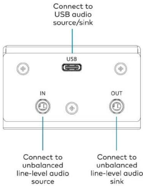
Connect a USB audio source to the USB port using a USB Type-C male connector. Connect an unbalanced line-level audio source to the INPUT TRS port.
Connect an unbalanced line-level audio sink device to the OUTPUT TRS port.
Reset the Device
A network reset or factory restore may be performed when troubleshooting.
CAUTION: These procedures should only be performed as a last resort to recover an unresponsive device. Both the Network Reset and Factory Restore procedure will clear certain device settings that cannot be recovered once the procedure is complete. Before performing these procedures, please contact Crestron True Blue Support via phone, email or chat as described at www.crestron.com/support.
Network Reset
- Ensure the device is powered on.
- Press and hold the SETUP button for up to 15 seconds until the SETUP LED flashes red.
The device will reboot, and the default network settings will be reset. The device will be reverted to its default hostname, with DHCP enabled, and no static IP set.
Factory Restore
- Turn off the device by disconnecting the power cable from the device.
- Press and hold the SETUP button and then reconnect the power cable while still holding the SETUP button. Continue holding the SETUP button for up to 30 seconds until the SETUP LED flashes.
The device will reboot, and all the factory default settings will be restored, such as audio settings, multicast addressing, etc.
CAUTION: Performing a factory restore will clear all settings from the device configuration.
DM-NAX-BTIO-1G Installation
Refer to the following sections to install the DM-NAX-BTIO-1G.
• In the Box on page 132
- Mount the Device on page 132
- Connect the Device on page 134
- Reset the Device on page 135
In the Box
Qty. Description
1 DM-NAX-BTIO-1G
Additional Items
1 Metal mounting bracket, steel (2016054)
2 Screw, 06-32, 1/4 in., Pan Head, Phillips (2007218)
2 Screws, 6-32 x 3/4 in., Truss Head, Combo (2009211)
Mount the Device
The DM-NAX-BTIO-1G can be mounted under a table or into a 1-gang electrical box.
Mounting under a Table
To mount the device under a table:
-
Align the included right angle surface mount bracket with the front panel of the device.
-
Using a Phillips screwdriver and the two included 6-32 x 1/4 in. pan head screws, attach the mounting bracket to the device.
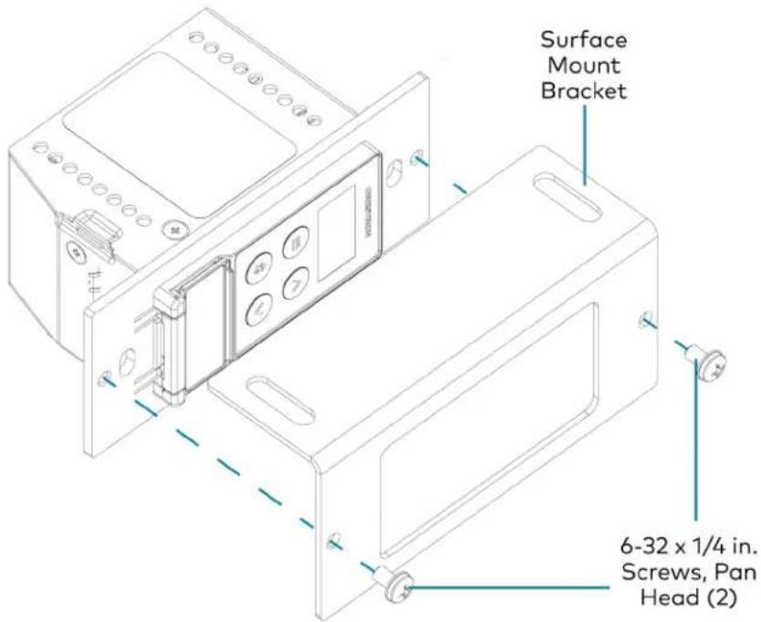
- Secure the device to the underside of a table using the appropriate mounting screws (not included).
Mounting into a 1-Gang Electrical Box
NOTES:
- The DM-NAX-BTIO-1G should only be mounted with a RACO® 3 in. x 2 in. x 2 in. gangable metal switch box with eight 0.5 in. knockouts and plaster ears (catalog ID #420), as it was designed to fit the box dimensions and knockout placements. Alternative metal switch boxes should not be used as they may have different knockout placements, which can lead to issues running the PoE connection to the unit due to cable bend radius restrictions.
- For thermal performance reasons, fully enclosed plastic back boxes should not be used with the DM-NAX-BTIO-1G. In installations where an enclosed back box is not required, the DM-NAX-BTIO-1G can be installed into most single gang metal or plastic mud rings.
- Connector boots should not be used on CAT5e (or greater) cables being connected to the DM-NAX-BTIO-1G to avoid cable bend radius issues.
To mount the wall plate into a 1-gang electrical box:
-
Using a Phillips screwdriver and two 6-32 x 3/4 in., truss head screws, attach the wall plate to the electrical box.
-
Using a Phillips screwdriver and two 6-32 x 1/4 in., flat head screws (not included), attach a FP-G1 decorator style faceplate (sold separately) to the wall plate.
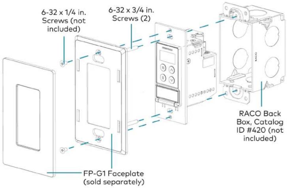
Connect the Device
Make connections to the front and top panels of the DM-NAX-BTIO-1G as described below.
Top Panel

NOTE: PoE is a PoE powered device (PD) port. In order for the port to receive PoE, it must be connected to a PoE compliant Ethernet switch.
Connect a PoE capable network switch to the PoE port.
Front Panel
Connect an unbalanced line-level audio input to the INPUT TRS port.
Connect an unbalanced line-level audio output to the OUTPUT TRS port.
Reset the Device
A network reset or factory restore may be performed when troubleshooting.
CAUTION: These procedures should only be performed as a last resort to recover an unresponsive device. Both the Network Reset and Factory Restore procedure will clear certain device settings that cannot be recovered once the procedure is complete. Before performing these procedures, please contact Crestron True Blue Support via phone, email or chat as described at www.crestron.com/support.
Network Reset
- Ensure the device is powered on.
- Press and hold the SETUP button for up to 15 seconds until the SETUP LED flashes red.
The device will reboot, and the default network settings will be reset. The device will be reverted to its default hostname, with DHCP enabled, and no static IP set.
Factory Restore
- Turn off the device by disconnecting the power cable from the device.
- Press and hold the SETUP button and then reconnect the power cable while still holding the SETUP button. Continue holding the SETUP button for up to 30 seconds until the SETUP LED flashes.
The device will reboot, and all the factory default settings will be restored, such as audio settings, multicast addressing, etc.
CAUTION: Performing a factory restore will clear all settings from the device configuration.
Configuration
The following products can be configured:
• DM-NAX-2XLRI-1G on page 137
• DM-NAX-8ZSA on page 189
• DM-NAX-16AIN on page 375
• DM-NAX-4ZSA-50 on page 256
• DM-NAX-4ZSP on page 314
• DM-NAX-AMP-X300 on page 407
• DM-NAX-AUD-IO on page 473
• DM-NAX-AUD-USB on page 529
• DM-NAX-BTIO-1G on page 585
DM-NAX-2XLRI-1G
This section describes how to configure the DM-NAX-2XLRI-1G.
Web Interface Configuration
The DM-NAX-2XLRI-1G web interface allows you to view status information and configure network and device settings.
Access the Web Interface
To access the web interface, do either of the following:
- Access the Web Interface with a Web Browser on page 138
- Access the Web Interface With the Crestron Toolbox™ Application on page 188
The web interface is accessed from a web browser. The following table lists operating systems and their corresponding supported web browsers.
Operating System and Supported Web Browsers
| OPERATING SYSTEM SUPPORTED WEB BROWSERS | |
| Windows® operating system | ChromeTM web browser, version 31 and laterFirefox® web browser, version 31 and laterInternet Explorer web browser, version 11 and laterMicrosoft Edge web browser |
| macOS® operating system | Safari® web browser, version 6 and laterChrome web browser, version 31 and laterFirefox web browser, version 31 and later |
Access the Web Interface with a Web Browser
- Enter the IP address of the DM-NAX-2XLRI-1G into a web browser.
NOTE: To obtain the IP address, use the Device Discovery Tool option in Crestron Toolbox™ application or an IP scanner application.
- If you are creating a user account for the first time, do the following; otherwise, skip to step 3.
a. Enter a username in the Username field.
b. Enter a password in the Password field.
c. Re-enter the same password in the Confirm Password field.
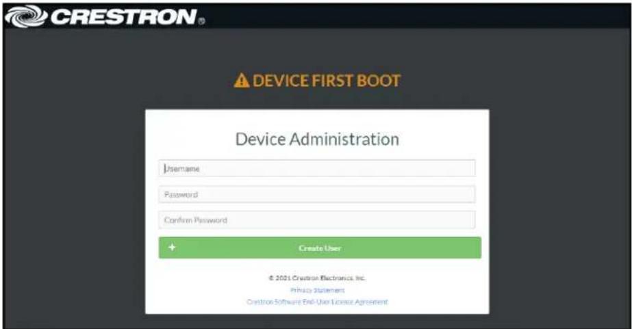
d. Click Create User. The Device Administration page appears.

- Enter the username in the Username field.
- Enter the password in the Password field.
- Click Sign In.
Action
The Action drop-down menu is displayed at the top right side of the interface and provides quick access to common device functions:
- Save Changes
- Revert
- Reboot
- Restore
- Update Firmware
- Download Logs
- Manage Certificates

Save Changes
Click Save Changes to save any changes made to the configuration settings.
Revert
Click Revert to revert the device back to the last saved configuration settings.
Reboot the DM-NAX-2XLRI-1G
Certain changes to the settings may require the DM-NAX-2XLRI-1G to be rebooted to take effect. To reboot the device, do the following:
- Click Reboot in the Actions drop-down menu. The Confirmation message box appears.

- Click Yes, Reboot Now to reboot the device. The Reboot message box appears.
Wait for the device reboot to complete before attempting to reconnect to the device.
Restore to Factory Default Settings
- Click Restore in the Actions drop-down menu to restore the settings of the DM-NAX-2XLRI-1G to factory defaults.
NOTE: When settings are restored, all settings, including the network settings, will revert to the factory default. If a static IP address is set, restoring the device to factory default settings will revert the IP address to the default DHCP mode.

- Click Yes in the Confirmation dialog to restore the DM-NAX-2XLRI-1G to factory settings. Click No to cancel the restore operation.
A dialog is displayed again, indicating that the restore process was successful and that the device rebooted.
You can also restore to factory settings by pressing and holding the SETUP button on the rear panel of the device with power disconnected then connect the power supply and continue to hold SETUP button for 30 seconds.
Update Firmware
-
Click Update Firmware in the Actions drop-down menu.
-
In the Firmware Upgrade dialog, click + Browse.
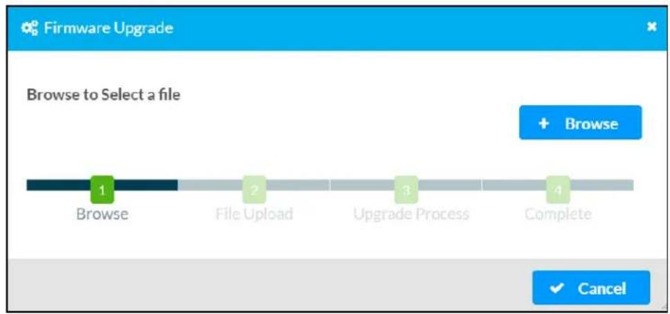
-
Locate and select the desired firmware file, and then click Open. The selected firmware file name is displayed in the Firmware Upgrade dialog.
-
Click Load and wait for the progress bar to complete and for the OK button in the message to become clickable.
-
Click OK. The device with new firmware can now be accessed.
Download Logs
- Click Download Logs in the Actions drop-down menu to download the device message logs for diagnostic purposes.
The log file is downloaded to the Downloads folder of the PC.
Manage Certificates
Use the Manage Certificates dialog to add, remove, and manage certificates used in 802.1x and other protected networks.
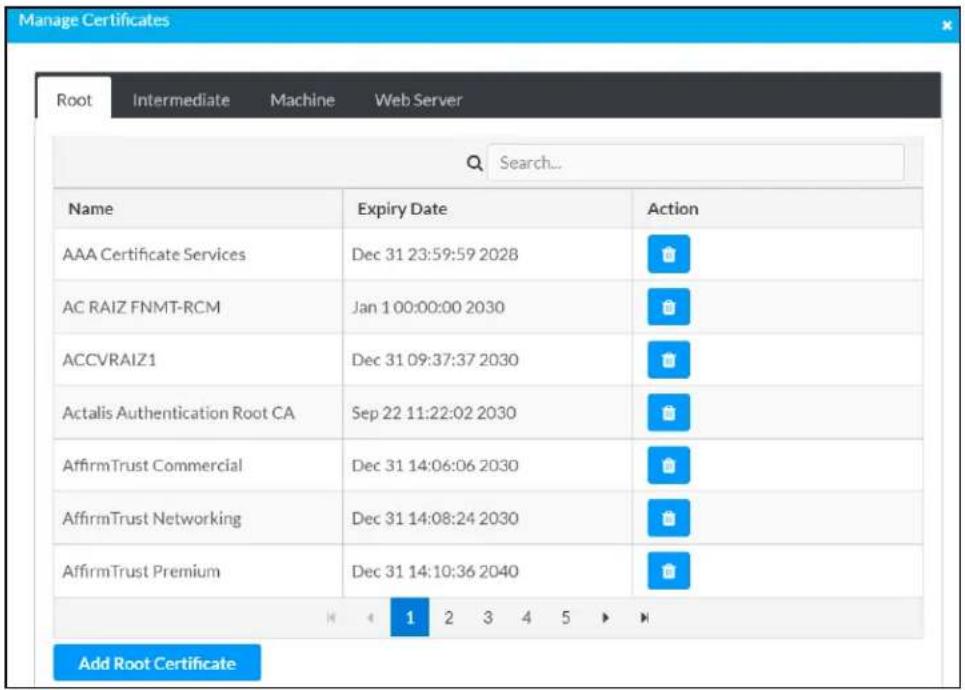
-
Click Manage Certificates in the Actions drop-down menu. The following certificate tabs are displayed:
-
Root: The Root certificate is used by the DM-NAX-2XLRI-1G to validate the network's authentication server. The DM-NAX-2XLRI-1G has a variety of Root certificates, self-signed by trusted CAs (Certificate Authorities) preloaded into the device. Root certificates must be self-signed.
- Intermediate: The Intermediate store holds non self-signed certificates that are used to validate the authentication server. These certificates will be provided by the network administrator if the network does not use self-signed Root certificates.
- Machine: The machine certificate is an encrypted PFX file that is used by the authentication server to validate the identity of the DM-NAX-2XLRI-1G. The machine certificate will be provided by the network administrator, along with the certificate password. For 802.1x, only one machine certificate can reside on the device.
- Web Server: The Web Server certificate is a digital file that contains information about the identity of the web server.
To Add Certificates
- Click the corresponding certificate tab.
- Click the Add Root Certificate button.
- Click the + Browse button.
- Locate and select the file, and then click the Open button.
NOTE: If the certificate is a Machine Certificate, enter the password provided by the network administrator.
- Click OK. This will add the certificate to the list box, displaying the file name and expiration date.
The certificate is now available for selection and can be loaded to the device.
To Delete Certificates
- Click the corresponding certificate tab.
- Click the trashcan button ( ) in the Actions column to delete the certificate.
- Click Yes when prompted to delete the certificate or No to cancel the deletion.
Status
The Status tab is the first page displayed when opening the interface of the DM-NAX-2XLRI-1G. It displays general information about the DM-NAX-2XLRI-1G (such as Model Name, Firmware Version, and Serial Number), current network settings (such as Host Name and IP Address, etc.), and input and output ports' current status.
The Status tab can be accessed at any time by clicking the Status tab of the DM-NAX-2XLRI-1G interface.

Information displayed on the Status tab is organized into different sections.
Device
The Device section displays the Model, Firmware Version, and Serial Number of the DM-NAX-2XLRI-1G.

Click + More Details to review additional information about the DM-NAX-2XLRI-1G.
![— More Details DM-NAX-BTIO-1G 1.0.0033.11191 Build Feb 13 2024 (531246) Updater 1.0.0033.11191 Bootloader 100.00 CCUI Version 1.1327.1 XIOSDK 3.6.2 IoTSDK 1:11.0 Build time 11:19:07 Product ID Cx7A09 Revision ID Cx0200 HDCP2X-SKE HDCP2X-SKE HDCP2X-SKE [v9.0000.00000,#FFFFFFF] PRE-BOOT [v9.0000.00000] BOOTLOADER [v9.0000.00000] ctrl-extclkin-pps Driver v1.1 ctrl-prod-info Driver v3.0 ctrl-lo-bt FW v2.0.98 PUF 1.0.0033.11191 Forced Auth Mode True](/content/2026/05/985127/images/99db982fd7ec49341fd3e4abc505a3ee917698549c1d7556dceee8e5bd7d6c43.jpg)
Network
The Network section displays network-related information about the DM-NAX-2XLRI-1G, including the Hostname, Domain Name, and DNS Servers.

NOTE: By default, the host name of the DM-NAX-2XLRI-1G consists of the model name followed by the MAC address of the device. For example, DM-NAX-2XLRI-1G-00107FB58088.
Click + Adapter 1 to display an expanded section that shows additional information. If + Adapter 1 is selected, click - Less details to collapse the section.
Control System
The Control System section displays connection information, consisting of the following:

- Encrypt Connection: ON or OFF
• IP ID: Reports the currently used IP ID of the DM-NAX-2XLRI-1G - IP Address/Hostname: The IP address of the control system
• Room ID: Displays the room ID - Status: OFFLINE or ONLINE
Settings
The Settings tab enables configuration of the DM-NAX-2XLRI-1G settings. The Settings page can be accessed at any time by clicking the Settings tab of the DM-NAX-2XLRI-1G interface.
Many options in the Settings tab are exclusive to a specific device mode: Residential or Commercial. The DM-NAX-2XLRI-1G is in Commercial mode by default.
This section provides the following information:
• Commercial Mode on page 146
• Residential Mode on page 163
Commercial Mode
This section provides the following information:
• System Setup on page 146
• Commissioning on page 151
• Output Channels on page 152
• Input Channels on page 156
• DM NAX Streams on page 158
- Mixing on page 162

System Setup
The System Setup section contains settings for Date/Time, Auto Update, Network, and Control System.
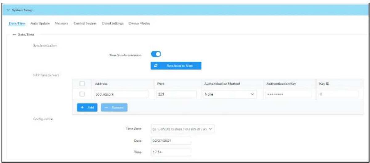
Date/Time
Use the Date/Time tab to configure the date and time settings of the DM-NAX-2XLRI-1G.

Time Synchronization
- Set the Time Synchronization toggle to the right position to enable or left position to disable time synchronization. By default, time synchronization is enabled.
- In the NTP Time Servers table, enter the URL of a NTP (Network Time Protocol) or SNTP (Simple Network Time Protocol) server. Up to three time servers can be added on a device.
- Click Synchronize Now to perform time synchronization between the device's internal clock and the time server.
Time Configuration
- Click on the Time Zone drop-down menu to select the applicable time zone.
- In the Date field, enter the current date.
- In the Time (24hr Format) field, enter the current time in 24-hour format.
Click the Save Changes button to save the settings.
Click Revert from the Actions drop-down menu to revert to the previous settings without saving.
Auto Update
The DM-NAX-2XLRI-1G can automatically check for and install firmware updates at scheduled intervals via the Auto Update feature.

- Set the Auto Update toggle to the right position to enable Auto Update.
- Define the URL to download the updates by doing either of the following:
a. Use the default URL to download the updates from the Crestron server.
b. Use a custom URL. Set the Custom URL toggle to the right position to enable a custom URL. In the Custom URL Path text box, enter the path to a custom manifest file in the F or SFTP URL format. Use the Crestron Auto Update Tool to generate a custom manifest file, then store the file on an FTP (File Transfer Protocol) or SFTP (Secure File Transfer Protocol) server.
- Set a schedule for the automatic firmware update by doing either of the following:
a. Select the desired Day of Week and Time of Day (24-hour format) values.
b. Set the Poll Interval by entering a value from 60 to 65535 minutes. A value of 0 disables the Poll Interval.
- Click Save Changes.
Clicking Update Now causes the device to check for a firmware update immediately. If a schedule was set in step 4 above, that schedule still remains in effect.
Network
The Network tab contains network-related settings for the DM-NAX-2XLRI-1G, including the Hostname, Domain, Primary Static DNS, and Secondary Static DNS.

NOTE: By default, the hostname of the DM-NAX-2XLRI-1G consists of the model name followed by the MAC address of the device. For example, DM-NAX-2XLRI-1G-00107FB58088.
Adapter 1
The Adapter 1 subheading contains settings for DHCP, IP Address, Subnet Mask, and Default Gateway of Ethernet adapter 1 on the rear panel of the device.
NOTE: DM NAX devices' internal processes use IP addresses in the 10x10 range. This IP range should be avoided when addressing DM NAX devices to prevent conflicts.
Set the DHCP toggle to enabled (right) or disabled (left) to specify whether the IP address of the DM-NAX-2XLRI-1G is to be assigned by a DHCP (Dynamic Host Configuration Protocol) server.
- Enabled: When DHCP is enabled (default setting), the IP address of the DM-NAX-2XLRI-1G is automatically assigned by a DHCP server on the local area network (LAN).
-
Disabled: When DHCP is disabled, manually enter information in the following fields:
-
Primary Static DNS: Enter a primary DNS IP address.
Secondary Static DNS: Enter a secondary DNS IP address.
IP Address: Enter a unique IP address for the DM-NAX-2XLRI-1G. - Subnet Mask: Enter the subnet mask that is set on the network.
Default Gateway: Enter the IP address that is to be used as the network's gateway.
To save any new network entries, click Save Changes.
Control System

- Click the Encrypt Connection button to navigate to the Security tab to configure encryption settings.
- Enter the username in the Control System Username field.
- Enter the password in the Control System Password field.
- Enter the Room ID in the Room ID field.
- Enter the IP ID of the DM-NAX-2XLRI-1G in the IP ID field.
- Enter the IP address or hostname of the control system in the IP Address/Hostname field.
- Click the Save Changes button to save the new entries. The Control System Save message box appears, indicating that the control system settings were saved successfully. Click the Revert button to revert to the previous settings without saving.
Cloud Settings
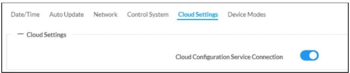
Set the Cloud Settings toggle to enabled (right) or disabled (left) to specify whether the DM-NAX-2XLRI-1G can communicate with the XiO Cloud® platform.
Device Modes
Use the Device Modes tab to configure the Application Mode of the DM-NAX-2XLRI-1G.
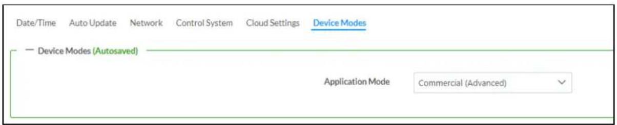
The Application Mode determines which options and controls are available.
- Select Residential (Standard) or Commercial (Advanced). A Reboot confirmation message box appears.

- Click Yes, Reboot Now to reboot the device into the selected mode. The Reboot message box appears.
- Wait for the device reboot to complete before attempting to reconnect to the device.
By default, the DM-NAX-2XLRI-1G is set to Commercial (Advanced) mode.
Commissioning
The Commissioning section provides a quick way to automatically assign multicast addresses to the device's internal audio-over-IP stream transmitters.

Click Assign Addresses to give each DM NAX transmitter in the DM-NAX-2XLRI-1G a unique multicast address beginning with the specified Starting Multicast Address. The valid range for Starting Multicast Address is 239.8.0.0 to 239.255.255.254.
NOTE: This will begin transmitting multicast traffic on your network, refer to the DM NAX Audio-over-IP System Design Guide document for details.
Output Channels
The Zones section contains the Volume and Mute settings for all zone outputs of the device, as well as an Edit option for more advanced settings within each zone.

bar
| Name | LineOut1 | LineOut2 | StreamOut1Ch1 | StreamOut1Ch2 | |---|---|---|---|---| | Volume (%) | 30 | 30 | 80 | 80 | | Signal Presence | | | | | | Signal Level | Nominal | Nominal | Nominal | Nominal | | Mute | | | | | | Action | Edit | Edit | Edit | Edit |Signal Presence indicates whether or not an audio signal is detected in that zone.
Signal Level indicates if the signal is Clipping or Nominal (non-clipping).
- Nominal: The signal level is within normal operating bounds and below the clipping threshold.
- Clipping: The signal level is clipping or above the -3 dB warning threshold and in danger of clipping.
Give each zone a friendly name using the Name column of the Zones table. If the device is paired with a control system, these names may be overwritten by the control system's program.
To configure the zone volume, do one of the following:
- Move the Volume slider up to increase or down to decrease the zone volume.
- Click the % arrows to increase or decrease the zone volume. Values range from 0 to 100%, adjustable in increments of 1%.
- Manually enter a value in the Volume field.
To mute all audio output from a zone, click its respective Mute button. To unmute the zone, click the Muted button.
Click Edit to view additional Zone and Output options.
Zone Settings
To configure the settings for an output channel, click the Edit button. The Edit Zone window appears.
DM-NAX-2XLRI-1G-C442683FB8AC > Zones LineOut1
Zone
Output
Zone
Click Zone to access the settings for Delay.

Delay
To set the delay, do one of the following:
- Move the Delay Time(ms) slider to the right to increase or to the left to decrease the delay time.
- Click the ms arrows to increase or decrease the delay. Values range from 0 ms to 85 ms, adjustable in increments of 1 ms.
- Manually enter a value in the Delay Time(ms) field.
NOTE: The Delay feature is only available on the line level output channels.
Output
Click Output to access the settings for Minimum/Maximum Volume and Signal.

Minimum/Maximum Volume

-
To set the minimum volume of the zone, do one of the following:
-
Move the Minimum slider to the right to increase or to the left to decrease the minimum volume.
- Click the % arrows to increase or decrease the minimum volume. Values range from 0 to 50%, adjustable in increments of 1%.
-
Manually enter a value in the Minimum field.
-
To set the maximum volume of the zone, do one of the following:
-
Move the Maximum slider to the right to increase or to the left to decrease the maximum volume.
- Click the % arrows to increase or decrease the maximum volume. Values range from 70 to 100%, adjustable in increments of 1%.
- Manually enter a value in the Maximum field.
NOTE: When a Minimum and Maximum volume are set, the 1-100% range represented by the Zone and Default volume controls are scaled to the range set. For example, if a Minimum of 10% and a Maximum of 80% are set for a zone, the 1-100% range of the Zone volume control is scaled to the 10%-80% range set as the Minimum and Maximum.
-
To set the default volume of the zone, do one of the following:
-
Move the Default slider to the right to increase or to the left to decrease the default volume.
- Click the % arrows to increase or decrease the default volume. Values range from 0 to 50% adjustable in increments of 1%.
- Manually enter a value in the Default field.
NOTE: The Default volume is applied as the Zone volume any time the zone receives a source route and no source was previously routed to that zone.
Signal

The Signal section is a read-only field that displays the Signal and Clipping status of the zone output.
- If an output signal is present but not clipping, Signal will display Present in green and Clipping will display None in green.
- If an output signal is present and clipping, Signal will display Present in green and Clipping will display Present in red.
- If no output signal is detected, Signal will display Not Present in red and Clipping will display None in green.
Input Channels
The Input Channels section is used to configure the Name, Compensation, and Mute attributes of the front panel XLR inputs on the DM-NAX-2XLRI-1G.

Configure Inputs
- If needed, enter a friendly name for each input in its Name field.
- To set an analog gain value for a given input, click the db arrows to increase or decrease the compensation. Values range from 0 dB to 60 dB, adjustable in increments of 1 dB.
-
To set a level compensation adjustment for a given input, do one of the following:
-
Move the Compensation slider up to increase or down to decrease the level compensation. Compensation increases or decreases the level of the incoming audio signal on any of the physical inputs on the device's rear panel.
- Click the db arrows to increase or decrease the compensation. Values range from -10 dB to 10 dB, adjustable in increments of 1 dB.
-
Manually enter a value in the Compensation field.
-
To switch between microphone level and line level input signals, expand the Mode drop-down and select the desired input signal level. By default, the XLR inputs are both set to Line level.
-
Set a channel's Phantom Power toggle to the right to enable +48V phantom power. Set the channel's Phantom Power toggle to the left to disable phantom power. By default, Phantom Power is disabled, and can only be enabled while the Mode of the channel is set to Mic.
-
To mute the signal from the corresponding input, set the Mute toggle to the right. To disable the mute, set the Mute toggle to the left. By default, Mute is disabled.
Monitor the device's input signals using the text indicators in the Signal Present and Clipping Detected columns:
• Signal Presence indicates whether or not a signal is detected in that zone.
- Clipping Detected indicates if the signal is Clipping or Nominal (non-clipping).
Click Edit to open the equalizer for a given input channel.
Equalizer Settings

Each XLR input channel of the DM-NAX-2XLRI-1G has a dedicated five-band equalizer that can be fully customized to tune the input signal to the needs of an install. Each band can have a discrete gain, filter type, center frequency, and bandwidth set, and can also be bypassed.
Do the following to configure a given equalizer band:
-
To set a band's gain, do one of the following:
-
Move the Gain slider up to increase or down to decrease the gain.
- Click the arrows to increase or decrease the gain. Values range from -40 dB to 20 dB, adjustable in increments of 0.1 dB.
-
Manually enter a value in the Gain field.
-
Select a filter type from the Type drop-down menu. By default, all bands are set to the EQ filter type. Some filter types will disable other settings in their respective band while enabled. For example, selecting the LowPass filter type for a band will disable that band's Gain and Bandwidth settings, since the LowPass filter applies a fixed roll-off slope at a set frequency. The available filter types are:
-
EQ: a fully parametric filter that can boost or cut a range of frequencies.
- Notch: a parametric filter designed to more precisely cut a frequency or range of frequencies. A notch filter can achieve a narrower bandwidth than the standard EQ parametric filter type.
- TrebleShelf: a filter that boosts or cuts all frequencies above a set frequency by a set gain.
- BassShelf: a filter that boosts or cuts all frequencies below a set frequency by a set gain.
- LowPass: a filter that fully cuts all frequencies above a set frequency using a fixed roll-off slope of -12 dB per octave.
-
HighPass: a filter that fully cuts all frequencies below a set frequency using a fixed roll-off slope of -12 dB per octave.
-
Set a center frequency for the equalizer band to tune a specific portion of the audible frequency spectrum. To set the center frequency, do one of the following:
-
Click the arrows to increase or decrease the frequency. Values range from 20 Hz to 20 kHz, adjustable in increments of 1 Hz. Each band has a default center frequency that will be applied if the Reset button at the bottom of the band is clicked.
-
Manually enter a value in the Frequency field.
-
Set a bandwidth to determine how wide of a frequency range is effected by the equalizer band. To set the bandwidth, do one of the following:
-
Click the arrows to increase or decrease the bandwidth. Values range from 0.1 octaves to 4.0 octaves, adjustable in increments of 0.1 octave.
-
Manually enter a value in the Bandwidth field.
-
The individual Bypass controls allow you to bypass a single band of equalization at a time for more granular A/B testing of a single filter. Set a band's Bypass toggle to the right position to bypass that band. Set the toggle to the left position to disable the bypass. By default, Bypass is disabled.
-
Each equalizer band has a Reset button that will reapply the default settings for that band.
Click Done to return to the Settings tab of the web user interface.
DM NAX Streams
The local inputs of the DM-NAX-2XLRI-1G can be made available as a DM NAX audio-over-IP stream. This single two channel stream will encode XLR input 1 as the left channel, and XLR input 2 as the right channel.
Click NAX Streams to expand the tab and display the following information.
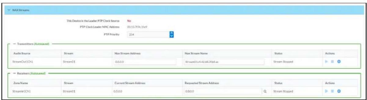
- Device is Master PTP Clock Source indicates whether the DM NAX device's PTP clock is the master clock on the network. Yes will be displayed in green when the local DM-NAX-2XLRI-1G's clock is the PTP master clock and No will be displayed in red when another PTP clock on the network is operating as the master clock.
- Master Clock Status displays the Master Clock ID of the device on the network that is currently acting as the master clock.
- PTP Priority: This sets the priority of the local DM NAX device's PTP clock relative to other clocks on the network. The default setting is 254 (one increment higher than the lowest possible value) so that the DM-NAX-2XLRI-1G will only operate as clock master if no other PTP master is present on the network. Valid values range from 1 to 255.
Configure Transmitters
To configure the DM NAX transmit stream, do the following.
- Enter a valid multicast address in the NAX Stream Address field.
- Enter a name in the NAX Stream Name field by which the stream can be identified. This stream name is associated with the DM NAX stream's multicast address by other DM NAX or AES67 devices, like a device hostname that resolves to a given IP address.
- Status indicates whether a stream is transmitting or not. When the stream has started or stopped, the Status column will update accordingly.
- Click the configure button (⚙️) in the Actions column. The Configure dialog appears:
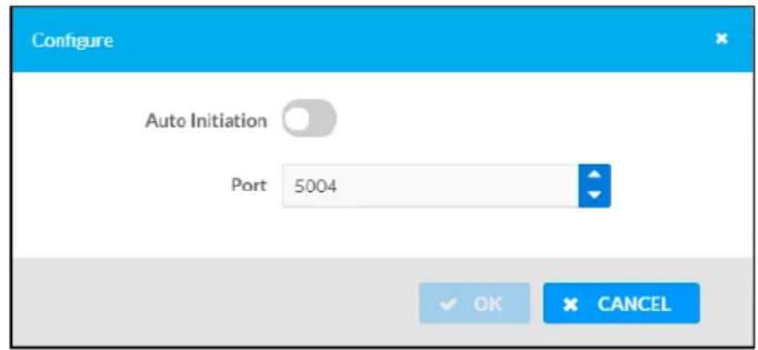
-
Set the Auto Initiation toggle to the right position to enable auto initiation. Set the toggle to the left position to disable auto initiation.
-
If Auto Initiation is enabled for a given stream, the stream will begin transmitting automatically and will be available as a multicast stream on your network at the specified multicast address.
-
If Auto Initiation is disabled for the input, the stream will not begin transmitting until it is manually initiated.
-
To set the port number, do one of the following:
-
Click the arrows to increase or decrease the port number by increments of 1.
-
Manually enter a port number in the Port field. The default port number for DM NAX streams is 5004.
-
Click OK to save or click Cancel to cancel the changes.
Configure Receivers
-
Enter the multicast address of a transmitting stream in the Requested Stream Address field to subscribe the receiver to the stream.
-
Click the configure button (💡) in the Actions column. The Configure dialog appears:
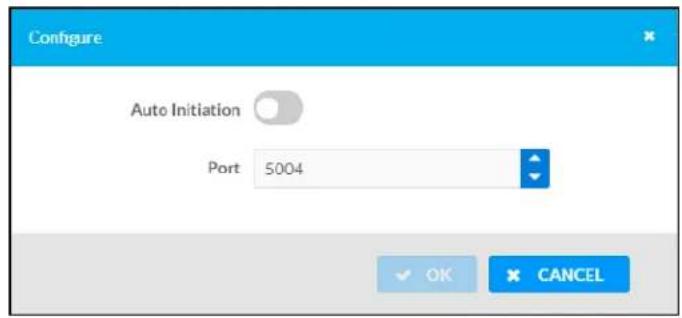
-
Set the Auto Initiation toggle to the right position to enable auto initiation. Set the toggle to the left position to disable auto initiation.
-
If Auto Initiation is enabled, the stream will begin automatically when the receiver subscribes to the transmitter.
-
If Auto Initiation is disabled, the stream will not begin until it is manually initiated.
-
To set the port number, do one of the following:
-
Click the arrows to increase or decrease the port number by increments of 1.
-
Manually enter a port number in the Port field. The default port number is 5004.
-
Click OK to save or click Cancel to cancel the changes.
Mixing
The Mixing matrix is used to route a local input or AES67 stream to an output on the DM-NAX-2XLRI-1G.
NOTE: To receive an AES67 stream from Dante devices, see OLH 1001151.
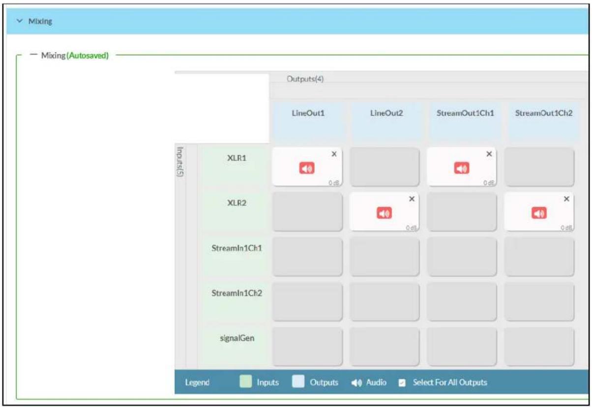
To route inputs to outputs on the device:
- Click the cells corresponding to the desired output that are to be paired for routing. Once a route is made, appears. The input that you have selected for a given row will route to the output corresponding to that row in the matrix.
• To break a given route click or✗
Each output can have any number of inputs routed to it. To adjust the mix setting for a route, click the dB value of the cell, then do one of the following:
- Move the slider up to increase or down to decrease the mix level.
- Click the arrows to increase or decrease the mix level.
- Manually enter a value in the field.
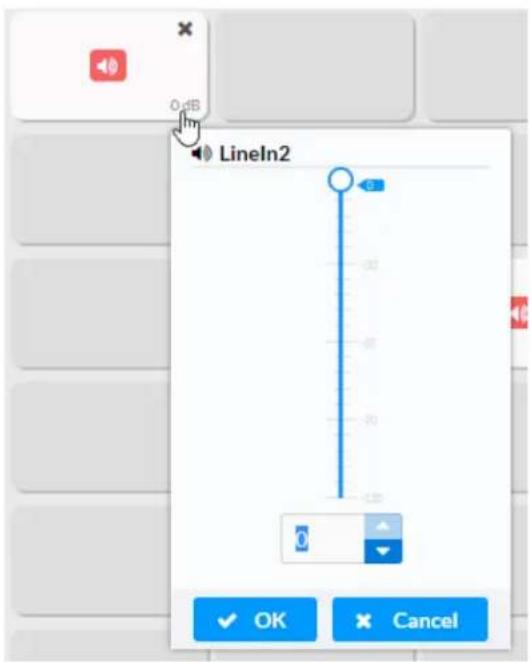
Residential Mode
This section provides the following information:
• System Setup on page 164
• Commissioning on page 168
• Output Channels on page 169
- Inputs on page 174
• NAX Streams on page 175
- Routing on page 177

System Setup
The System Setup section displays information about the Date/Time, Auto Update, Network, Control System, Cloud Settings, and Device Modes.
Date/Time
Use the Date/Time section to configure the date and time settings of the DM-NAX-2XLRI-1G.

Time Synchronization
-
Set the Time Synchronization toggle to the right position to enable or left position to disable time synchronization. By default, time synchronization is enabled.
-
In the NTP Time Servers table, enter the URL of a NTP (Network Time Protocol) or SNTP (Simple Network Time Protocol) server. Up to three time servers can be added on a device.
- Click Synchronize Now to perform time synchronization between the device's internal clock and the time server.
Time Configuration
- Click on the Time Zone drop-down menu to select the applicable time zone.
- In the Date field, enter the current date.
- In the Time (24hr Format) field, enter the current time in 24-hour format.
Click the Save Changes button to save the settings.
Click Revert from the Actions drop-down menu to revert to the previous settings without saving.
Auto Update
The DM-NAX-2XLRI-1G can automatically check for and install firmware updates at scheduled intervals via the Auto Update feature.

- Set the Auto Update toggle to the right position to enable Auto Update.
- Define the URL to download the updates by doing either of the following:
a. Use the default URL to download the updates from the Crestron server.
b. Use a custom URL. Set the Custom URL toggle to the right position to enable a custom URL. In the Custom URL Path text box, enter the path to a custom manifest file in the F or SFTP URL format. Use the Crestron Auto Update Tool to generate a custom manifest file, then store the file on an FTP (File Transfer Protocol) or SFTP (Secure File Transfer Protocol) server.
- Set a schedule for the automatic firmware update by doing either of the following:
a. Select the desired Day of Week and Time of Day (24-hour format) values.
b. Set the Poll Interval by entering a value from 60 to 65535 minutes. A value of 0 disables the Poll Interval.
4. Click Save Changes.
Clicking Update Now causes the device to check for a firmware update immediately. If a schedule was set in step 4 above, that schedule still remains in effect.
Network
The Network section contains network-related settings for the DM-NAX-2XLRI-1G, including the Hostname, Domain, Primary Static DNS, and Secondary Static DNS.

NOTE: By default, the host name of the DM-NAX-2XLRI-1G consists of the model name followed by the MAC address of the device. For example, DM-NAX-2XLRI-1G-00107FB58088.
Adapter 1
The Adapter 1 subheading contains settings for DHCP, IP Address, Subnet Mask, and Default Gateway of Ethernet adapter 1 on the rear panel of the device.
NOTE: DM NAX devices' internal processes use IP addresses in the 10x10 range. This IP range should be avoided when addressing DM NAX devices to prevent conflicts.
Set the DHCP toggle to enabled (right) or disabled (left) to specify whether the IP address of the DM-NAX-2XLRI-1G is to be assigned by a DHCP (Dynamic Host Configuration Protocol) server.
- Enabled: When DHCP is enabled (default setting), the IP address of the DM-NAX-2XLRI-1G is automatically assigned by a DHCP server on the local area network (LAN).
- Disabled: When DHCP is disabled, manually enter information in the following fields:
Primary Static DNS: Enter a primary DNS IP address.
Secondary Static DNS: Enter a secondary DNS IP address.
IP Address: Enter a unique IP address for the DM-NAX-2XLRI-1G.
- Subnet Mask: Enter the subnet mask that is set on the network.
Default Gateway: Enter the IP address that is to be used as the network's gateway.
To save any new network entries, click Save Changes.
Control System
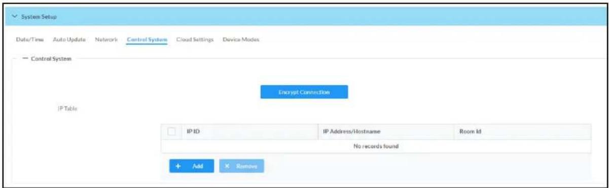
- Click the Encrypt Connection button to navigate to the Security tab to configure encryption settings.
- Enter the username in the Control System Username field.
- Enter the password in the Control System Password field.
- Enter the Room ID in the Room ID field.
- Enter the IP ID of the DM-NAX-2XLRI-1G in the IP ID field.
- Enter the IP address or hostname of the control system in the IP Address/Hostname field.
- Click the Save Changes button to save the new entries. The Control System Save message box appears, indicating that the control system settings were saved successfully. Click the Revert button to revert to the previous settings without saving.
Cloud Settings

Set the Cloud Settings toggle to enabled (right) or disabled (left) to specify whether the DM-NAX-2XLRI-1G can communicate with the XiO Cloud® platform.
Device Modes
Use the Device Modes section to configure the Application Mode.
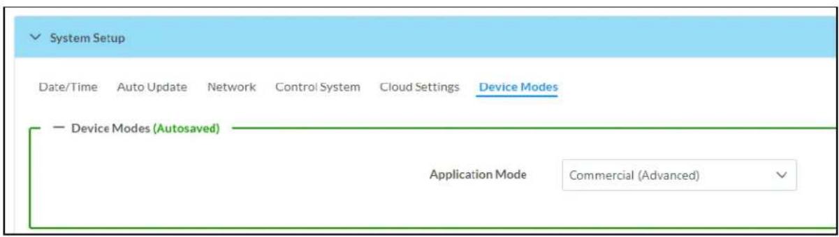
- Application Mode: The Application Mode determines which options and controls are available.
Select Residential (Standard) or Commercial (Advanced). A Reboot confirmation message box appears.

- Click Yes, Reboot Now to reboot the device into the selected mode. The Reboot message box appears.
- Wait for the device reboot to complete before attempting to reconnect to the device.
Commissioning
The Commissioning section provides a quick way to automatically assign multicast addresses to the device's internal audio-over-IP stream transmitters.

Click Assign Addresses to give each DM NAX transmitter in the DM-NAX-2XLRI-1G a unique multicast address beginning with the specified Starting Multicast Address. The valid range for Starting Multicast Address is 239.8.0.0 to 239.127.255.254.
NOTE: This will begin transmitting multicast traffic on your network, refer to the General Network Requirements document for details.
Output Channels
The Output Channels section contains the Volume and Mute settings for all zone outputs of the device, as well as a Configure option for more advanced settings within each zone.

Give each zone a friendly name using the Name column of the Zones table. If the device is paired with a control system, these names may be overwritten by the control system's program.
To configure the zone volume, do one of the following:
- Move the Volume slider to the right to increase or to the left to decrease the zone volume.
- Click the % arrows to increase or decrease the zone volume. Values range from 0 to 100%, adjustable in increments of 1%.
- Manually enter a value in the Volume field.
To mute all audio output from a zone, click its respective Mute button. To unmute the zone, click the Muted button.
Zone Settings
To configure zone settings, click the Configure button (Configure). The Edit Zone window appears.
Zone
Click Zone to access the settings for Balance, and Delay.

Balance
To adjust the left/right balance of the stereo output signal, do one of the following:
- Move the Balance slider to the right to shift the stereo balance to the right channel or to the left to shift the balance to the left.
- Click the arrows to adjust the balance left or right. The up arrow shifts the balance to the right while the down arrow shifts the balance to the left.
- Manually enter a value in the Balance field. Values range from -50 to 50, adjustable in increments of 1. Positive values shift the balance to the right while negative values shift the balance to the left.
Delay
To set the delay, do one of the following:
- Move the Delay Time(ms) slider to the right to increase or to the left to decrease the delay time.
- Click the ms arrows to increase or decrease the delay. Values range from 0 ms to 85 ms, adjustable in increments of 1 ms.
- Manually enter a value in the Delay Time(ms) field.
Output
Click Output to access the settings for Minimum/Maximum Volume, Stereo/Mono, Signal, Bussing Volume Offset, and Signal Generator.

Minimum/Maximum Volume

-
To set the minimum volume of the zone, do one of the following:
-
Move the Minimum slider to the right to increase or to the left to decrease the minimum volume.
- Click the % arrows to increase or decrease the minimum volume. Values range from 0 to 50%, adjustable in increments of 1%.
-
Manually enter a value in the Minimum field.
-
To set the maximum volume of the zone, do one of the following:
-
Move the Maximum slider to the right to increase or to the left to decrease the maximum volume.
- Click the % arrows to increase or decrease the maximum volume. Values range from 70 to 100%, adjustable in increments of 1%.
- Manually enter a value in the Maximum field.
NOTE: When a Minimum and Maximum volume are set, the 1-100% range represented by the Zone and Default volume controls are scaled to the range set. For example, if a Minimum of 10% and a Maximum of 80% are set for a zone, the 1-100% range of the Zone volume control is scaled to the 10%-80% range set as the Minimum and Maximum.
-
To set the default volume of the zone, do one of the following:
-
Move the Default slider to the right to increase or to the left to decrease the default volume.
- Click the % arrows to increase or decrease the default volume. Values range from 0 to 50% adjustable in increments of 1%.
- Manually enter a value in the Default field.
NOTE: The Default volume is applied as the Zone volume any time the zone receives a source route and no source was previously routed to that zone.
Stereo/Mono

Select either Stereo or Mono from the Stereo/Mono radio buttons. If Stereo is selected, both output channels can have independent audio content. If Mono is selected, both output channels receive the same audio content.
Signal

The Signal section is a read-only field that displays the Signal and Clipping status of the zone output.
- If an output signal is present but not clipping, Signal will display Present in green and Clipping will display None in green.
- If an output signal is present and clipping, Signal will display Present in green and Clipping will display Present in red.
- If no output signal is detected, Signal will display Not Present in red and Clipping will display None in green.
Bussing Volume Offset

Bussing Volume Offset is an additional level compensation applied to the zone relative to any other zones it is grouped with via the Bussing feature.
To set the bussing volume offset, do one of the following:
- Move the Bussing Volume Offset slider to the right to increase or to the left to decrease the offset.
- Click the db arrows to increase or decrease the offset. Values range from -12 dB to 12 dB, adjustable in increments of 1 dB.
- Manually enter a value in the Bussing Volume Offset field.
Signal Generator

The DM-NAX-2XLRI-1G has a built-in signal generator that allows an integrator to send an audio signal to the output for testing purposes.
-
To route the signal generator to the zone output, click the Signal Generator button so that it displays Active and is highlighted in blue. To unroute the signal generator on the zone output, click the Signal Generator button so that it displays Inactive and is highlighted in grey. By default, the signal generator is not routed to the zone output.
-
To adjust the signal generator's volume, do one of the following:
-
Move the Signal Generator Volume slider right to increase or left to decrease the volume.
- Click the arrows to increase or decrease the signal generator volume. Values range from 0 to 100, adjustable in increments of 1.
- Manually enter a value in the Signal Generator Volume field.
Advanced Signal Generator
The advanced signal generator settings control the signal type of the signal generator, and allow the left and right channel to be enabled or disabled independently of one another.
- Set the Left Channel toggle to the right position to enable the left channel of the signal. Set the toggle to the left position to disable the left channel. By default, Left Channel is enabled.
- Set the Right Channel toggle to the right position to enable the right channel of the signal. Set the toggle to the left position to disable the right channel. By default, Right Channel is enabled.
- Select an audio test signal type from the Signal Type drop-down menu. The available signal types are:
- Tone: Generates a 1 kHz sine wave tone.
- Pink Noise: Generates pink noise.
- White Noise: Generates white noise.
Click Done to return to the Settings tab of the web user interface.
Inputs
The Inputs section is used to configure the Name, Compensation, and Mute attributes of the available analog, digital, and media streaming inputs on the DM-NAX-2XLRI-1G.

Configure Inputs
- If needed, enter a friendly name for each input in its Name field.
-
To set a level compensation adjustment for a given input, do one of the following:
-
Move the Compensation slider up to increase or down to decrease the level compensation. Compensation increases or decreases the level of the incoming audio signal on any of the physical inputs on the device's rear panel.
- Click the db arrows to increase or decrease the compensation. Values range from -10 dB to 10 dB, adjustable in increments of 1 dB.
-
Manually enter a value in the Compensation field.
-
To mute the signal from the corresponding input, set the Mute toggle to the right. To disable the mute, set the Mute toggle to the left. By default, Mute is disabled.
Monitor the device's input signals using the text indicators in the Signal Present and Clipping Detected columns:
• Signal Presence indicates whether or not a signal is detected in that zone.
- Clipping Detected indicates if the signal is Clipping or Nominal (non-clipping).
NAX Streams
The local inputs of the DM-NAX-2XLRI-1G can be made available as a DM NAX audio-over-IP stream. This single two channel stream will encode XLR input 1 as the left channel, and XLR input 2 as the right channel.
Click NAX Streams to expand the tab and display the following information.
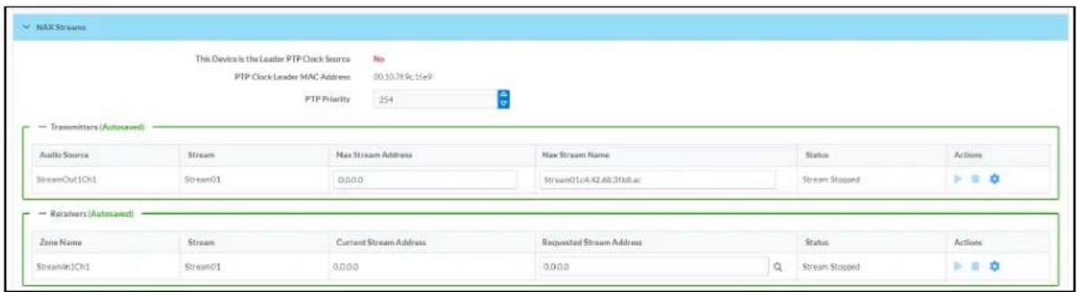
- Device is Master PTP Clock Source indicates whether the device is the master for PTP on the network. Yes will be displayed in green when the local DM-NAX-2XLRI-1G is the PTP clock master and No will be displayed in red when another PTP clock on the network is operating as the master clock.
- Master Clock Status displays the Master Clock ID of the device on the network that acts as the Master Clock.
- PTP Priority: This sets the priority of the local DM NAX device's PTP clock relative to other clocks on the network. The default setting is 254 (one increment higher than the lowest possible value) so that the DM-NAX-2XLRI-1G will only operate as clock master if no other PTP master is present on the network. Valid values range from 1 to 255.
Configure Transmitters

To configure a DM NAX transmit stream, do the following.
- Enter a valid multicast address in the NAX Stream Address field.
- Enter a name in the NAX Stream Name field by which the stream can be identified. This stream name is associated with the DM NAX stream's multicast address by other DM NAX or AES67 devices, like a device hostname that resolves to a given IP address.
- Status indicates whether a stream is transmitting or not. When the stream has started or stopped, the Status column will update accordingly.
- Click the configure button (💡) in the Actions column. The Configure dialog appears:
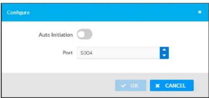
-
Set the Auto Initiation toggle to the right position to enable auto initiation. Set the toggle to the left position to disable auto initiation.
-
If Auto Initiation is enabled for a given stream, the stream will begin transmitting automatically and will be available as a multicast stream on your network at the specified multicast address.
-
If Auto Initiation is disabled for the input, the stream will not begin transmitting until it is manually initiated.
-
To set the port number, do one of the following:
-
Click the arrows to increase or decrease the port number by increments of 1.
-
Manually enter a port number in the Port field. The default port number for DM NAX streams is 5004.
-
Click OK to save or click Cancel to cancel the changes.
Configure Receivers
| Zone Name | Stream | Current Stream Address | Requested Stream Address | Status | Actions | |
| Zone_Amp1 | Stream01 | 0.0.0.0 | 0.0.0.0 | Q | Stream Stopped | |
| Zone_Amp2 | Stream02 | 0.0.0.0 | 0.0.0.0 | Q | Stream Stopped | |
- Enter the multicast address of a transmitting stream in the Requested Stream Address field to subscribe the receiver to the stream.
- Click the configure button (💡) in the Actions column. The Configure dialog appears:
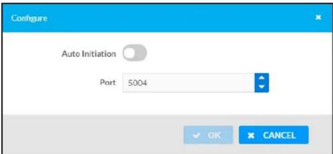
-
Set the Auto Initiation toggle to the right position to enable auto initiation. Set the toggle to the left position to disable auto initiation.
-
If Auto Initiation is enabled, the stream will begin automatically when the receiver subscribes to the transmitter.
• If Auto Initiation is disabled, the stream will not begin until it is manually initiated. -
To set the port number, do one of the following:
-
Click the arrows to increase or decrease the port number by increments of 1.
• Manually enter a port number in the Port field. The default port number is 5004. -
Click OK to save or click Cancel to cancel the changes.
Routing
The Routing section is used to route a local input or AES67 stream to a Zone on the DM-NAX-2XLRI-1G.
NOTE: To receive an AES67 stream from Dante devices, see OLH 1001151.

To route an input to a zone, click the box in the routing matrix where the zone's row overlaps the corresponding input's column. Once a route is made, appears. To break a given route click or . To route a single input to all zones, click on the icon under the input's name.
Security
Click the Security tab to configure security for users and groups and to allow different levels of access to the DM-NAX-2XLRI-1G functions. By default, security is disabled.
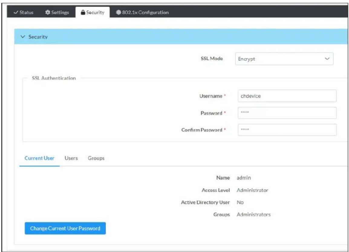
Select Encrypt and Validate, Encrypt, or OFF in the SSL Mode drop-down menu, to specify whether to use encryption. By default, SSL Mode is set to OFF.
Current User
Click the Current User tab to view read-only information or to change the password for the current user.

-
Click the Change Current User Password button to provide a new password for the current user.
-
In the Change Password dialog, enter the current password in the Current Password field, the new password in the Password field, and then re-enter the same new password in the Confirm Password field.
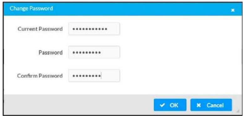
- Click OK to save or click Cancel to cancel the changes.
Users
Click the Users tab to view and edit user settings. The Users tab can be used to add or remove local and Active Directory users and preview information about users.

Use the Search Users field to enter search term(s) and display users that match the search criteria.
If users listed in the Users table span across multiple pages, navigate through the list of users by clicking a page number or by using the left or right arrows at the bottom of the Users pane to move forward or backward through the pages.
Each page can be set to display 5, 10, or 20 users by using the drop-down menu to the right of the navigation arrows.
Information about existing users is displayed in table format and the following details are provided for each user.
- Username: Displays the name of the user.
- AD User: Displays whether the user requires authentication using Active Directory.
Click the corresponding button in the Actions column to view detailed user information or to delete the user.
To create a new user, click the Create User button.
Create a New Local User
-
Click the Create User button in the User tab.
-
In the Create User dialog, enter the following:
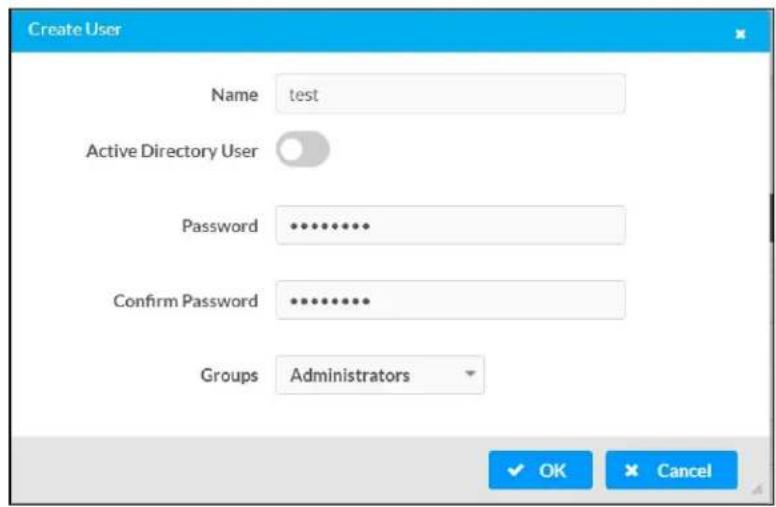
a. Enter a user name in the Name field. A valid user name can consist of alphanumeric characters (letters a-z, A-Z, numbers 0-9) and the underscore "_" character.
b. Enter a password in the Password field; re-enter the same password in the Confirm Password field.
c. Assign the access level by selecting one or more groups from the Groups drop-down list.
NOTE: Make sure that the Active Directory User toggle is disabled.
- Click OK to save or click Cancel to cancel the changes.
Add an Active Directory User
Users cannot be created or removed from the Active Directory server, but access can be granted to an existing user in the Active Directory server.
To grant access to an Active Directory user, you can either add the user to a local group on the DM-NAX-2XLRI-1G, or add the Active Directory group(s) that they are a member of to the DM-NAX-2XLRI-1G.
To add an Active Directory user.
- Click the Create User button.
- In the Create User dialog, enter the following.

a. Enter a user name in the Name field in the format "Domain\UserName", for example "crestronlabs.com\JohnSmith". Valid user names can contain alphanumeric characters (letters a-z, A-Z, numbers 0-9) and the underscore "_" character.
b. Select one or more groups from the Groups drop-down list.
NOTE: Make sure that the Active Directory User toggle is set to enabled.
- Click OK to save or click Cancel to cancel the changes.
Delete User
Click the trashcan button (☐) in the Actions column to delete the user. Click Yes when prompted to delete the user or No to cancel the deletion.
After a user is removed from a group, they lose any access rights associated with that group. Note that the user account is not deleted by the delete user operation.
View User Details
Click the information button (0) in the Actions column to view information for the selected user. The User Details dialog displays the following information for the selected user.
- Name: Displays the name of the selected user.
• Active Directory User: Displays whether the user is an Active Directory user. - Group: Displays group(s) the selected user is part of.

Click OK to close the User Details dialog and to return to the Users tab.
Update User Details

- Click the edit button() in the Actions column to update information for the selected user.
- Enter a password in the Password field; re-enter the same password in the Confirm Password field.
- Select one or more groups to assign the user to from the Groups drop-down list.
- Click OK to save or click Cancel to cancel the changes.
The Update User dialog also displays the following read-only information for the selected user.
• Name: Displays the name of the user.
• Active Directory User: Displays whether the user is an Active Directory user.
Groups
Click the Groups tab to view and edit group settings. The Groups tab can be used to add local and Active Directory groups, remove local and Active Directory groups, and preview information about a group.
Use the Search Groups field to enter search term(s) and display groups that match the search criteria.
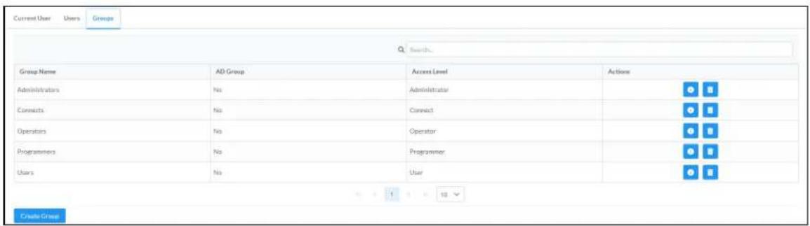
If groups listed in the Groups table span across multiple pages, navigate through the groups by clicking a page number or by using the left or right arrows at the bottom of the Groups pane to move forward or backward through the pages.
Additionally, each page can be set to display 5, 10, or 20 groups by using the drop-down menu to the right of the navigation arrows.
Existing groups are displayed in a table and the following information is provided for each group:
• Group Name: Displays the name of the group.
• AD Group: Displays whether the group requires authentication using Active Directory.
- Access Level: Displays the predefined access level assigned to the group (Administrator, Programmer, Operator, User, or Connect).
Click the corresponding button in the Actions column to view detailed group information (☐) or to delete ☐ selected group.
Click on the Create Group button in the Groups tab to create new group.
Create Local Group

- Click the Create Group button.
- In the Create Group dialog, enter the following:
a. Enter the group name in the Name field.
b. Assign the group access level by selecting a predefined access level (Administrator, Connect, Operator, Programmer, User) from the Access Level drop-down list.
NOTE: Make sure that the Active Directory Group toggle is disabled.
- Click OK to save. Click Cancel to cancel the changes.
Add Active Directory Group
A group cannot be created or removed from the Active Directory server, but access can be granted to a existing group in Active Directory.

Once the group is added, all members of that group will have access to the DM-NAX-2XLRI-1G.
- Click the Create Group button.
- In the Create Group dialog enter the following:
a. Enter the group name in the Name field, for example "Engineering Group". Note that group names are case sensitive; a space is a valid character that can be used in group names.
- Assign the group access level by selecting a predefined access level (Administrator, Connect, Operator, Programmer, User) from the Access Level drop-down list.
NOTE: Make sure that the Active Directory Group toggle is enabled.
- Click OK to save. Click Cancel to cancel the changes.
Delete a Group
Click the trashcan button (☐) in the Actions column to delete a group. Click Yes when prompted to delete the group or No to cancel the deletion.
When a group is deleted, users in the group are not removed from the device or Active Directory server. However, because a user's access level is inherited from a group(s), users within the deleted group will lose access rights associated with the group.
View Group Details
Click the information button (6) in the Actions column to view information for the selected group. The Group Details dialog lists the following information for the selected group.
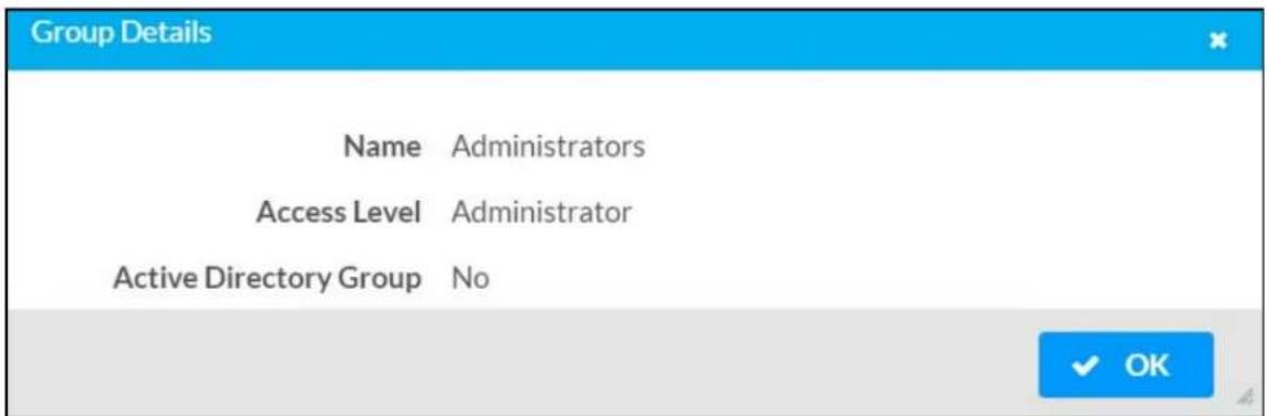
• Name: Displays the name of the group.
- Access Level: Displays the access level of the group and its users.
• Active Directory Group: Displays whether the group is an Active Directory group.
Click OK to close the Group Details dialog and to return to the Groups tab.
802.1x Configuration
The DM-NAX-2XLRI-1G has built-in support for the 802.1X standard (an IEEE network standard designed to enhance the security of wireless and Ethernet LANs. The standard relies on the exchange of messages between the device and the network's host, or authentication server), allowing communication with the authentication server and access to protected corporate networks.
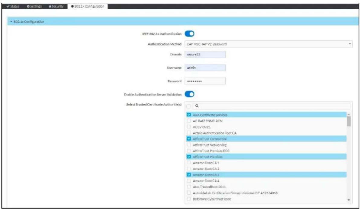
To Configure DM-NAX-2XLRI-1G for 802.1X Authentication
-
Set the IEEE 802.1X Authentication toggle to enabled. This will enable all options on the 802.1X dialog.
-
Select the Authentication method: EAP-TLS Certificate or EAP-MSCHAP V2 Password according to the network administrator's requirement.
-
Do either one of the following:
- Select EAP-TLS Certificate, click Action/Manage Certificates to upload the required machine certificate. The machine certificate is an encrypted file that will be supplied by the network administrator, along with the certificate password.
- Select EAP-MSCHAP V2 Password, enter the username and password supplied by the network administrator into the Username and Password fields. This method does not require the use of a machine certificate, only the user name and password credentials.
- If you enabled the Enable Authentication Server Validation option, this will enable the Select Trusted Certificate Authoritie(s) list box which contains signed Trusted Certificate Authorities (CAs) preloaded into the DM-NAX-2XLRI-1G.
Select the check box next to each CA whose certificate can be used for server validation, as specified by the network administrator.
If the network does not use any of the listed certificates, the network administrator must provide a certificate, which must be uploaded manually via the Manage Certificates functionality.
-
If required, type the domain name of the network in the Domain field.
-
When the 802.1X settings are configured as desired, click Save Changes to save the changes to the device and reboot it. Click Revert to cancel any changes.
Access the Web Interface With the Crestron Toolbox Application
To access the web interface by opening a web browser within the Crestron Toolbox™ application, do the following:
-
Open the Crestron Toolbox application.
-
From the Tools menu, select Device Discovery Tool. You can also access the Device Discovery Tool by clicking the Device Discovery Tool button ( ) in the Crestron Toolbox toolbar. The DM-NAX-8ZSA is discovered and listed in the device list on the left side of the screen. The associated host name, IP address, and firmware version are also displayed.
NOTE: If there is security software running on the computer, a security alert might be displayed when the Crestron Toolbox application attempts to connect to the network. Make sure to allow the connection, so that the Device Discovery Tool can be used.
-
In the Device Discovery Tool list, double-click your device.
-
Enter your credentials in the Authentication Required dialog that opens, and then click Log In.
-
Click the Web Configuration button in the Configuration page displayed on the left side of the Device Discovery Tool.
DM-NAX-8ZSA
This section describes how to configure the DM-NAX-8ZSA.
Web Interface Configuration
The DM-NAX-8ZSA web interface allows you to view status information and configure network and device settings.
Access the Web Interface
To access the web interface, do either of the following:
- Access the Web Interface with a Web Browser on page 190
- Access the Web Interface With the Crestron Toolbox™ Application on page 255
The web interface is accessed from a web browser. The following table lists operating systems and their corresponding supported web browsers.
Operating System and Supported Web Browsers
| OPERATING SYSTEM SUPPORTED WEB BROWSERS | |
| Windows® operating system | ChromeTM web browser, version 31 and laterFirefox® web browser, version 31 and laterInternet Explorer web browser, version 11 and laterMicrosoft Edge web browser |
| macOS® operating system | Safari® web browser, version 6 and laterChrome web browser, version 31 and laterFirefox web browser, version 31 and later |
Access the Web Interface with a Web Browser
- Enter the IP address of the DM-NAX-8ZSA into a web browser.
NOTE: To obtain the IP address, use the Device Discovery Tool option in Crestron Toolbox™ application or an IP scanner application.
- If you are creating a user account for the first time, do the following; otherwise, skip to step 3.
a. Enter a username in the Username field.
b. Enter a password in the Password field.
c. Re-enter the same password in the Confirm Password field.
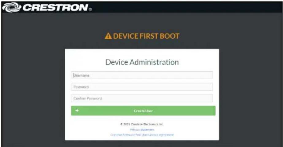
d. Click Create User. The Device Administration page appears.

- Enter the username in the Username field.
- Enter the password in the Password field.
- Click Sign In.
Action
The Action drop-down menu is displayed at the top right side of the interface and provides quick access to common device functions:
- Save Changes
- Revert
- Reboot
- Restore
- Update Firmware
- Download Logs
- Manage Certificates
- Manage Audio Profiles
- Download Configuration
- Upload Configuration

Save Changes
Click Save Changes to save any changes made to the configuration settings.
Revert
Click Revert to revert the device back to the last saved configuration settings.
Reboot the DM-NAX-8ZSA
Certain changes to the settings may require the DM-NAX-8ZSA to be rebooted to take effect. To reboot the device, do the following:
- Click Reboot in the Actions drop-down menu. The Confirmation message box appears.

- Click Yes, Reboot Now to reboot the device. The Reboot message box appears.
Wait for the device reboot to complete before attempting to reconnect to the device.
Restore to Factory Default Settings
- Click Restore in the Actions drop-down menu to restore the settings of the DM-NAX-8ZSA to factory defaults.
NOTE: When settings are restored, all settings, including the network settings, will revert to the factory default. If a static IP address is set, restoring the device to factory default settings will revert the IP address to the default DHCP mode.
- Click Yes in the Confirmation dialog to restore the DM-NAX-8ZSA to factory settings. Click No to cancel the restore operation.
A dialog is displayed again, indicating that the restore process was successful and that the device rebooted.
You can also restore to factory settings by pressing and holding the SETUP button on the rear panel of the device with power disconnected then connect the power supply and continue to hold SETUP button for 30 seconds.
Update Firmware
-
Click Update Firmware in the Actions drop-down menu.
-
In the Firmware Upgrade dialog, click + Browse.
-
Locate and select the desired firmware file, and then click Open. The selected firmware file name is displayed in the Firmware Upgrade dialog.
-
Click Load and wait for the progress bar to complete and for the OK button in the message to become clickable.
-
Click OK. The device with new firmware can now be accessed.
Download Logs
- Click Download Logs in the Actions drop-down menu to download the device message logs for diagnostic purposes.
The log file is downloaded to the Downloads folder of the PC.
Manage Certificates
Use the Manage Certificates dialog to add, remove, and manage certificates used in 802.1x and other protected networks.
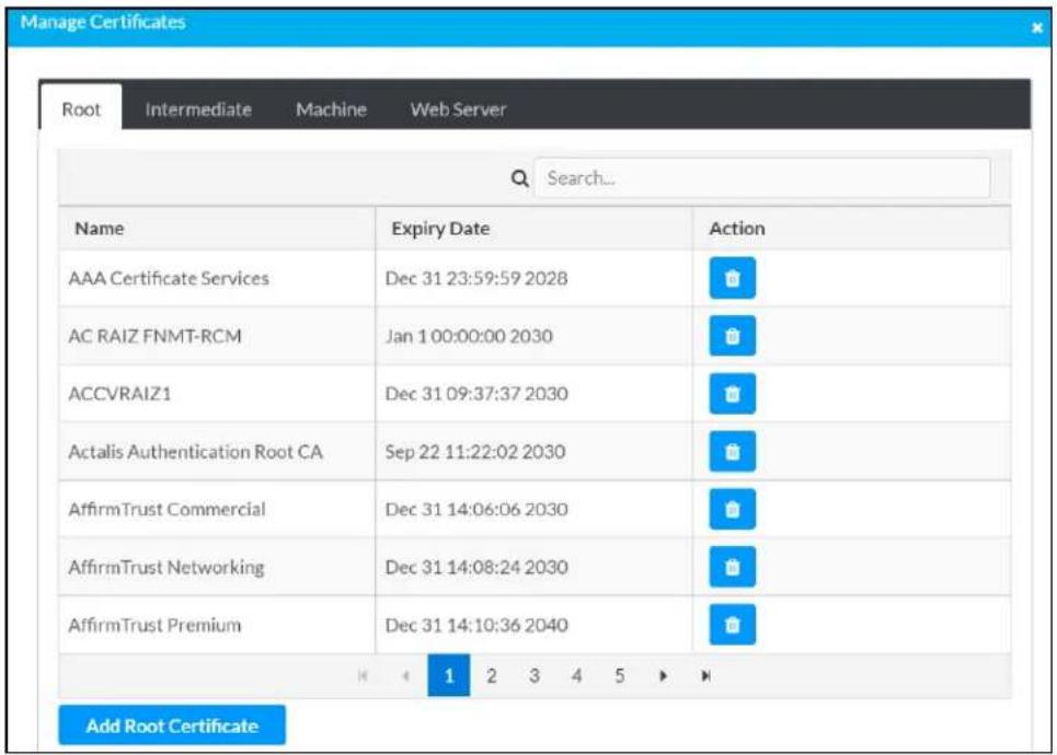
-
Click Manage Certificates in the Actions drop-down menu. The following certificate tabs are displayed:
-
Root: The Root certificate is used by the DM-NAX-8ZSA to validate the network's authentication server. The DM-NAX-8ZSA has a variety of Root certificates, self-signed by trusted CAs (Certificate Authorities) preloaded into the device. Root certificates must be self-signed.
- Intermediate: The Intermediate store holds non self-signed certificates that are used to validate the authentication server. These certificates will be provided by the network administrator if the network does not use self-signed Root certificates.
- Machine: The machine certificate is an encrypted PFX file that is used by the authentication server to validate the identity of the DM-NAX-8ZSA. The machine certificate will be provided by the network administrator, along with the certificate password. For 802.1x, only one machine certificate can reside on the device.
- Web Server: The Web Server certificate is a digital file that contains information about the identity of the web server.
To Add Certificates
-
Click the corresponding certificate tab.
-
Click the Add Root Certificate button.
-
Click the + Browse button.
-
Locate and select the file, and then click the Open button.
NOTE: If the certificate is a Machine Certificate, enter the password provided by the network administrator.
- Click OK. This will add the certificate to the list box, displaying the file name and expiration date. The certificate is now available for selection and can be loaded to the device.
To Delete Certificates
-
Click the corresponding certificate tab.
-
Click the trashcan button ( ) in the Actions column to delete the certificate.
-
Click Yes when prompted to delete the certificate or No to cancel the deletion.
Manage Audio Profiles
Use the Manage Audio Profiles dialog to add, remove, and manage the audio profiles of speakers.
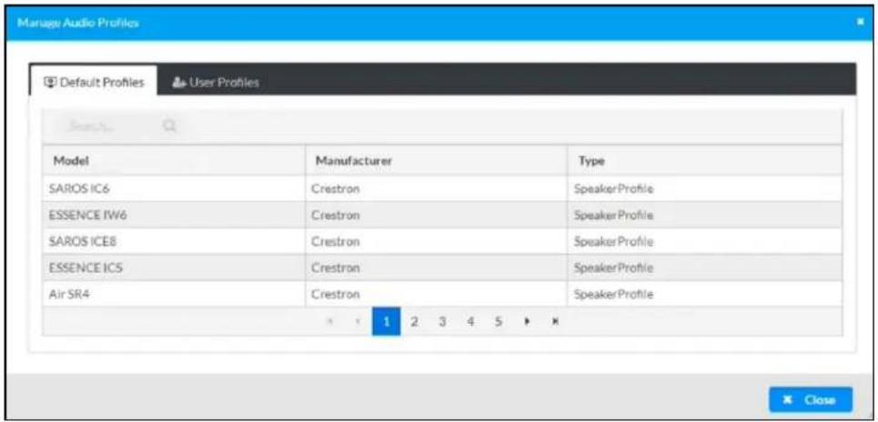
Click Manage Audio Profiles in the Actions drop-down menu. The following audio profiles tabs are displayed, providing information such as Model, Manufacturer, and Type of the speaker profiles:
- Default Profiles: Lists the default library of included speaker profiles.
- User Profiles: Lists the custom, user loaded profiles, and allows them to be loaded and removed.
In the Search field, enter the speaker's profile name to search for the profile. The speaker profile matching the search criteria is displayed.
NOTE: To create a custom speaker profile, see OLH 1001820.
To Add a Speaker Profile

- Click the User Profiles tab.
- Click the + Add Profiles button.
- Click the + Browse button.
- Locate and select the .prof file, and then click the Open button.
- Click the Upload button.
- Click OK. This will add the profile to the list box.
The speaker profile is now available for selection and can be applied to the speaker.
To Delete a Speaker Profile
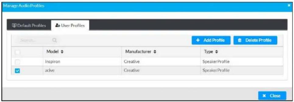
- Click the User Profiles tab.
- Select the checkbox corresponding to the audio profile that needs to be deleted.
- Click Delete Profile button.
The speaker profile is deleted.
Download Configuration
Click Download Configuration to download a TGZ file containing the settings data for the DM NAX device.
NOTE: User accounts for accessing the device, streaming service accounts, multicast addresses, and stream names are not saved in this configuration file.
Upload Configuration
- Click Upload Configuration to upload a TGZ file that will overwrite the current settings of the DM NAX device with a saved configuration.
CAUTION: Be sure to load a TGZ file for the same DM NAX device type while using the Load Configuration feature. For example, if loading a TGZ file to a DM-NAX-8ZSA, be sure that the TGZ file originated from a DM-NAX-8ZSA.
- Click Browse to navigate to the desired TGZ file in your file browser. Double-click the file or highlight it and click Open.

- Click Upload to begin the file upload process. A progress bar will indicate the status of the configuration file upload.

- Once the upload is complete, the device will require a reboot. Click Yes, Reboot Now to begin the reboot, or click No to return to the web UI.
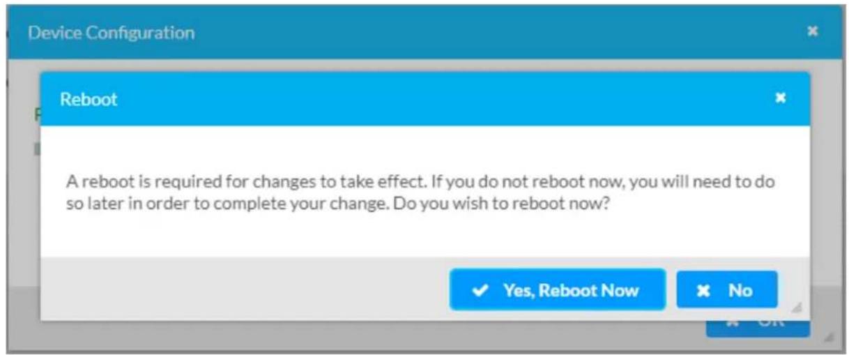
NOTE: Any changes made after the configuration file upload, but before a device reboot, may be overwritten when the device is rebooted.
Status
The Status tab is the first page displayed when opening the interface of the DM-NAX-8ZSA. It displays general information about the DM-NAX-8ZSA (such as Model Name, Firmware Version, and Serial Number), current network settings (such as Host Name and IP Address, etc.), and input and output ports' current status.
The Status tab can be accessed at any time by clicking the Status tab of the DM-NAX-8ZSA interface.
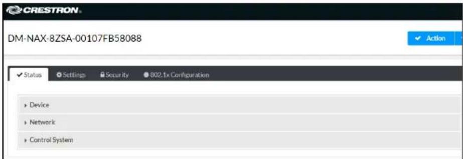
Information displayed on the Status tab is organized into different sections.
Device
The Device section displays the Model, Firmware Version, and Serial Number of the DM-NAX-8ZSA.
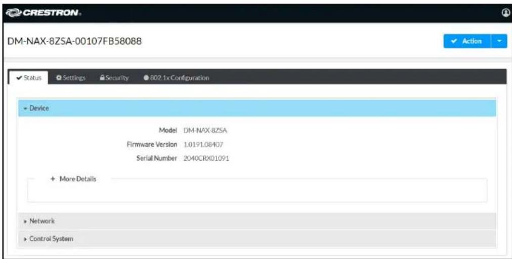
Click + More Details to review additional information about the DM-NAX-8ZSA.

Network
The Network section displays network-related information about the DM-NAX-8ZSA, including the Hostname, Domain Name, and DNS Servers.
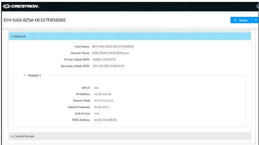
NOTE: By default, the host name of the DM-NAX-8ZSA consists of the model name followed by the MAC address of the device. For example, DM-NAX-8ZSA-00107FB58088.
Click + Adapter 1 to display an expanded section that shows additional information. If + Adapter 1 is selected, click - Less details to collapse the section.
NOTE: The + Adapter 2 option appears when the dual Ethernet ports on the DM-NAX-8ZSA are set to isolate traffic using the Port Selection feature.
Control System
The Control System section displays connection information, consisting of the following:
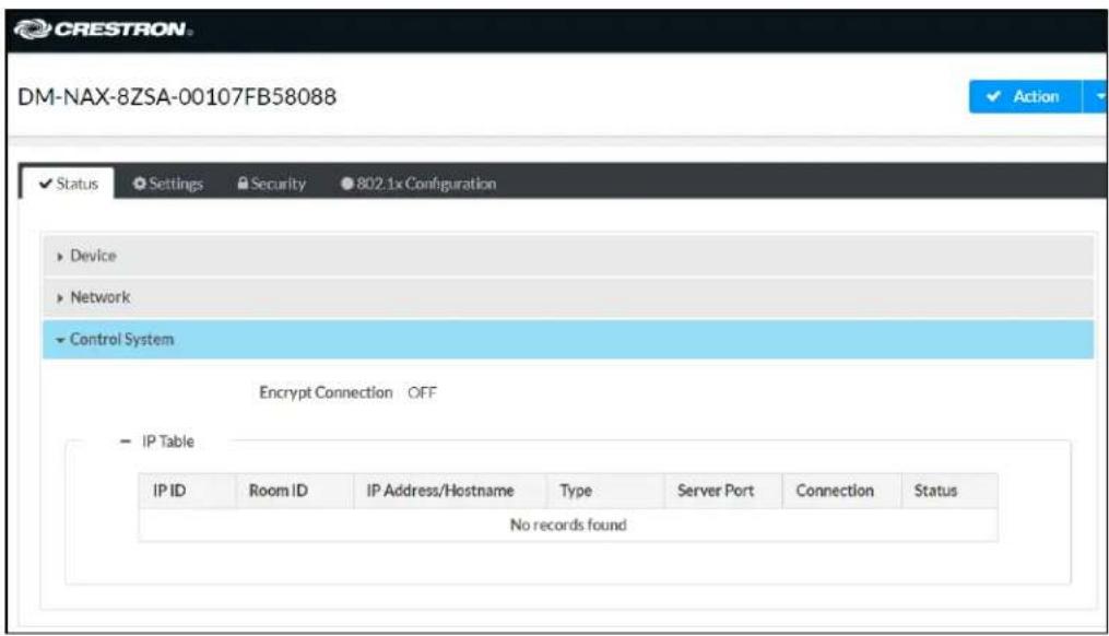
- Encrypt Connection: ON or OFF
• IP ID: Reports the currently used IP ID of the DM-NAX-8ZSA
• IP Address/Hostname: The IP address of the control system
• Room ID: Displays the room ID
• Status: OFFLINE or ONLINE
Settings
The Settings tab enables you to configure the DM-NAX-8ZSA settings. The Settings page can be accessed at any time by clicking the Settings tab of the DM-NAX-8ZSA interface.

Settings available on the Settings tab are organized into different sections.
System Setup
The System Setup section contains settings for Date/Time, Auto Update, Network, and Control System.
Date/Time
Use the Date/Time section to configure the date and time settings of the DM-NAX-8ZSA.
Time Synchronization
-
Set the Time Synchronization toggle to the right position to enable or left position to disable time synchronization. By default, time synchronization is enabled.
-
In the NTP Time Servers table, enter the URL of a NTP (Network Time Protocol) or SNTP (Simple Network Time Protocol) server. Up to three time servers can be added on a device.
-
Click Synchronize Now to perform time synchronization between the device's internal clock and the time server.
Time Configuration
- Click on the Time Zone drop-down menu to select the applicable time zone.
- In the Date field, enter the current date.
- In the Time (24hr Format) field, enter the current time in 24-hour format.
Click the Save Changes button to save the settings.
Click Revert from the Actions drop-down menu to revert to the previous settings without saving.
Auto Update
The DM-NAX-8ZSA can automatically check for and install firmware updates at scheduled intervals via the Auto Update feature.
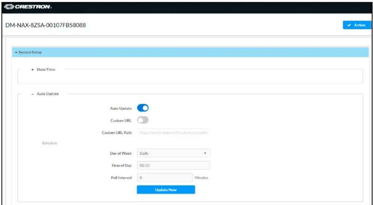
- Set the Auto Update toggle to the right position to enable Auto Update.
- Define the URL to download the updates by doing either of the following:
a. Use the default URL to download the updates from the Crestron server.
b. Use a custom URL. Set the Custom URL toggle to the right position to enable a custom URL. In the Custom URL Path text box, enter the path to a custom manifest file in the F or SFTP URL format. Use the Crestron Auto Update Tool to generate a custom manifest file, then store the file on an FTP (File Transfer Protocol) or SFTP (Secure File Transfer Protocol) server.
- Set a schedule for the automatic firmware update by doing either of the following:
a. Select the desired Day of Week and Time of Day (24-hour format) values.
b. Set the Poll Interval by entering a value from 60 to 65535 minutes. A value of 0 disables the Poll Interval.
- Click Save Changes.
Clicking Update Now causes the device to check for a firmware update immediately. If a schedule was set in step 4 above, that schedule still remains in effect.
Network
The Network section contains network-related settings for the DM-NAX-8ZSA, including the Hostname, Domain, Primary Static DNS, and Secondary Static DNS.

NOTE: By default, the hostname of the DM-NAX-8ZSA consists of the model name followed by the MAC address of the device. For example, DM-NAX-8ZSA-00107FB58088.
Adapter 1
The Adapter 1 subheading contains settings for DHCP, IP Address, Subnet Mask, and Default Gateway of Ethernet adapter 1 on the rear panel of the device.
NOTES:
- An + Adapter 2 option only appears when the dual Ethernet ports on the DM-NAX-8ZSA are set to isolate traffic using the Port Selection feature. The settings for Adapter 2 are identical to those available for Adapter 1.
- DM NAX devices' internal processes use IP addresses in the 10x10.16nge. This IP range should be avoided when addressing DM NAX devices to prevent conflicts.
Set the DHCP toggle to enabled (right) or disabled (left) to specify whether the IP address of the DM-NAX-8ZSA is to be assigned by a DHCP (Dynamic Host Configuration Protocol) server.
- Enabled: When DHCP is enabled (default setting), the IP address of the DM-NAX-8ZSA is automatically assigned by a DHCP server on the local area network (LAN).
-
Disabled: When DHCP is disabled, manually enter information in the following fields:
-
Primary Static DNS: Enter a primary DNS IP address.
Secondary Static DNS: Enter a secondary DNS IP address.
IP Address: Enter a unique IP address for the DM-NAX-8ZSA. - Subnet Mask: Enter the subnet mask that is set on the network.
Default Gateway: Enter the IP address that is to be used as the network's gateway.
To save any new network entries, click Save Changes.
Control System
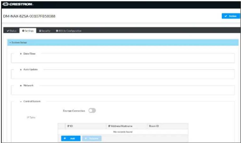
- Click the Encrypt Connection button to navigate to the Security tab to configure encryption settings.
- Enter the username in the Control System Username field.
- Enter the password in the Control System Password field.
- Enter the Room ID in the Room ID field.
- Enter the IP ID of the DM-NAX-8ZSA in the IP ID field.
- Enter the IP address or hostname of the control system in the IP Address/Hostname field.
- Click the Save Changes button to save the new entries. The Control System Save message box appears, indicating that the control system settings were saved successfully. Click the Revert button to revert to the previous settings without saving.
Commissioning
The Commissioning section provides a quick way to automatically assign multicast addresses to all of the device's internal audio-over-IP stream transmitters.

Click Assign Addresses to give each DM NAX transmitter in the DM-NAX-8ZSA a unique multicast address beginning with the specified Starting Multicast Address. The valid range for Starting Multicast Address is 239.8.0.0 to 239.255.255.231.
NOTE: This will begin transmitting multicast traffic on your network, refer to the DM NAX Audio-over-IP System Design Guide document for details.
Chimes
The Chimes section allows the built-in chime files to be assigned to any of the output zones on the device.

For each chime file, click the cells corresponding to the desired Zones for playback of that specific chime sound. You can assign multiple chimes to the same zone. To view all available chimes, use the or arrows at the left of the matrix to change pages.
To configure the chime volume of a zone:
- Click the icon corresponding to the zone. A Configure window appears.

-
To set the volume, do one of the following:
-
Move the Volume slider to the right to increase or to the left to decrease the chime volume
- Click the % arrows to increase or decrease the chime volume. Values range from 0 to 100%, adjustable in increments of 1%.
- Manually enter a value in the Volume field.
NOTE: The chime volume is independent of the zone volume control.
-
Set the Do Not Disturb toggle to the right to mute all chimes for the zone. Set the Do Not Disturb toggle to the left to unmute the chimes.
-
Click OK to apply the new settings.
Zones
The Zones section contains the Volume and Mute settings for all zone outputs of the device, as well as a Configure option for more advanced settings within each zone.

Give each zone a friendly name using the Name column of the Zones table. If the device is paired with a control system, these names may be overwritten by the control system's program.
To configure the zone volume, do one of the following:
- Move the Volume slider to the right to increase or to the left to decrease the zone volume.
- Click the % arrows to increase or decrease the zone volume. Values range from 0 to 100%, adjustable in increments of 1%.
- Manually enter a value in the Volume field.
To mute all audio output from a zone, click its respective Mute button. To unmute the zone, click the Muted button.
Zone Settings
To configure zone settings, click the Configure button (Configure). The Edit Zone window appears.

Zone
Click Zone to access the settings for Tone, Balance, and Delay.

Tone

The Tone section provides adjustments for the Tone Profile, Bass, Treble, Loudness, and Night Mode settings of the zone output.
NOTE: The Tone Profile, Bass, Treble, and Loudness settings in the Tone section are all applied separately from the Equalizer Settings for the zone. This means that any adjustments made in the Tone section will stack with those made in the Equalizer Settings section.
-
To select a tone profile preset for the zone, select an option from the Tone Profile drop-down menu. The available options are Off, Classical, Jazz, Pop, Rock, and Spoken Word. By default, Off is selected.
-
Bass: To adjust the bass, do one of the following:
-
Move the Bass slider to the right to increase or to the left to decrease the bass.
- Click the db arrows to increase or decrease the db. Values range from -12 db to 12 db, adjustable in increments of 1 db.
-
Manually enter a value in the Bass field.
-
Treble: To adjust the treble, do one of the following:
-
Move the Treble slider to the right to increase or to the left to decrease the treble.
- Click the db arrows to increase or decrease the db. Values range from -12 db to 12 db, adjustable in increments of 1 db.
-
Manually enter a value in the Treble field.
-
To enable the loudness setting on the zone output, slide the Loudness switch to the right. To disable loudness, slide the Loudness switch to the left.
-
The Night Mode feature applies subtle processing to restrict the dynamic range of the zone audio, to allow for lower listening levels at night or in rooms where higher listening levels would be disruptive. To select a dynamics processing level, select an option from the Night Mode drop-down menu. The available options are Off, Low, Medium, and High. By default, Off is selected.
Balance

To adjust the left/right balance of the stereo output signal, do one of the following:
- Move the Balance slider to the right to shift the stereo balance to the right channel or to the left to shift the balance to the left.
- Click the arrows to adjust the balance left or right. The up arrow shifts the balance to the right while the down arrow shifts the balance to the left.
- Manually enter a value in the Balance field. Values range from -50 to 50, adjustable in increments of 1. Positive values shift the balance to the right while negative values shift the balance to the left.
Delay

To set the delay, do one of the following:
- Move the Delay Time(ms) slider to the right to increase or to the left to decrease the delay time.
- Click the ms arrows to increase or decrease the delay. Values range from 0 ms to 250 ms, adjustable in increments of 1 ms.
- Manually enter a value in the Delay Time(ms) field.
Output
Click Output to access the settings for Minimum/Maximum Volume, Stereo/Mono, Signal, Bussing Volume Offset, Configure Speaker Profile, Speaker Configuration, Casting, Speaker/Faults, Line Out, Signal Generator, Advanced Signal Generator, and Equalizer Settings.

Minimum/Maximum Volume

bar
| Category | Value | Percentage | | ---------- | ----- | ---------- | | Minimum | 14 | 14% | | Maximum | 86 | 86% | | Default | 27 | 27% |-
To set the minimum volume of the zone, do one of the following:
-
Move the Minimum slider to the right to increase or to the left to decrease the minimum volume.
- Click the % arrows to increase or decrease the minimum volume. Values range from 0 to 50%, adjustable in increments of 1%.
-
Manually enter a value in the Minimum field.
-
To set the maximum volume of the zone, do one of the following:
-
Move the Maximum slider to the right to increase or to the left to decrease the maximum volume.
- Click the % arrows to increase or decrease the maximum volume. Values range from 70 to 100%, adjustable in increments of 1%.
- Manually enter a value in the Maximum field.
NOTE: When a Minimum and Maximum volume are set, the 1-100% range represented by the Zone and Default volume controls are scaled to the range set. For example, if a Minimum of 10% and a Maximum of 80% are set for a zone, the 1-100% range of the Zone volume control is scaled to the 10%-80% range set as the Minimum and Maximum.
- To set the default volume of the zone, do one of the following:
- Move the Default slider to the right to increase or to the left to decrease the default volume.
- Click the % arrows to increase or decrease the default volume. Values range from 0 to 50% adjustable in increments of 1%.
- Manually enter a value in the Default field.
NOTE: The Default volume is applied as the Zone volume any time the zone receives a source route and no source was previously routed to that zone.
Stereo/Mono

-
Select either Stereo or Mono from the Stereo/Mono field.
-
Select the zone configuration from the Zone Configuration drop-down menu. The available values are Standard, Bridged, Bridged 2.1, Bridged Sub 2.1, and Bridged Mono. See the diagrams below for the output signal flow applied in each configuration.
NOTE: The Stereo/Mono field is disabled for the Bridged 2.1, Bridged Sub 2.1, and Bridged Mono zone configurations.
Stereo - Standard
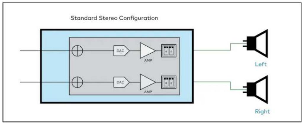
flowchart
graph LR
    A["Input"] --> B["DAC"]
    B --> C["AMP"]
    C --> D["Left Speaker"]
    E["Input"] --> F["DAC"]
    F --> G["AMP"]
    G --> H["Right Speaker"]
Stereo - Bridged
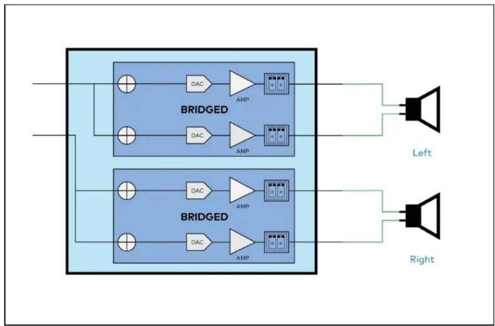
flowchart
graph TD
    A["Input"] --> B["BRIDGED Block 1"]
    A --> C["BRIDGED Block 2"]
    B --> D["DAC"]
    B --> E["AMP"]
    C --> F["DAC"]
    C --> G["AMP"]
    D --> H["Speaker"]
    E --> I["Speaker"]
    F --> J["Speaker"]
    G --> K["Speaker"]
    L["Left"] --> M["Speaker"]
    N["Right"] --> O["Speaker"]
Mono - Standard
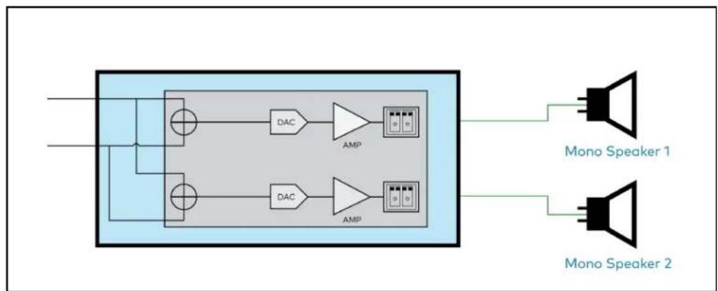
flowchart
graph TD
    A["Input"] --> B["Block"]
    B --> C["DAC"]
    B --> D["DAC"]
    C --> E["AMP"]
    D --> F["AMP"]
    E --> G["Mono Speaker 1"]
    F --> H["Mono Speaker 2"]
Mono - Bridged
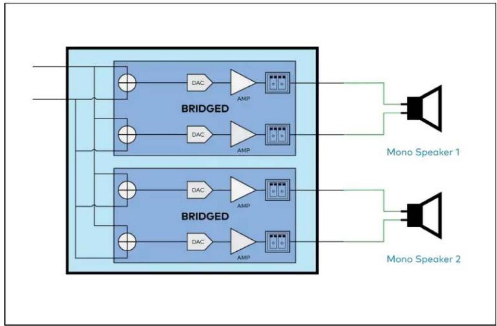
flowchart
graph TD
    A["Input"] --> B["BRIGDED"]
    B --> C["DAC"]
    B --> D["AMP"]
    B --> E["DAC"]
    B --> F["AMP"]
    G["Mono Speaker 1"] --> H["Speaker"]
    I["Mono Speaker 2"] --> J["Speaker"]
Bridged 2.1

flowchart
graph TD
    A["Input"] --> B["BRIDGED"]
    B --> C["DAC"]
    B --> D["AMP"]
    D --> E["Left"]
    B --> F["DAC"]
    B --> G["AMP"]
    G --> H["Right"]
    B --> I["DAC"]
    B --> J["AMP"]
    J --> K["Sub"]
    style A fill:#f9f,stroke:#333
    style B fill:#bbf,stroke:#333
    style C fill:#dfd,stroke:#333
    style D fill:#dfd,stroke:#333
    style E fill:#dfd,stroke:#333
    style F fill:#dfd,stroke:#333
    style G fill:#dfd,stroke:#333
    style H fill:#dfd,stroke:#333
    style I fill:#dfd,stroke:#333
    style J fill:#dfd,stroke:#333
Bridged Sub 2.1

flowchart
graph TD
    A["Input"] --> B["DAC"]
    B --> C["AMP"]
    C --> D["Left"]
    A --> E["DAC"]
    E --> F["AMP"]
    F --> G["Right"]
    A --> H["BRIDGED"]
    H --> I["Output"]
    style A fill:#f9f,stroke:#333
    style H fill:#bbf,stroke:#333
    style B fill:#dfd,stroke:#333
    style E fill:#dfd,stroke:#333
    style F fill:#dfd,stroke:#333
    style H fill:#dfd,stroke:#333
    style I fill:#dfd,stroke:#333
Bridged Mono
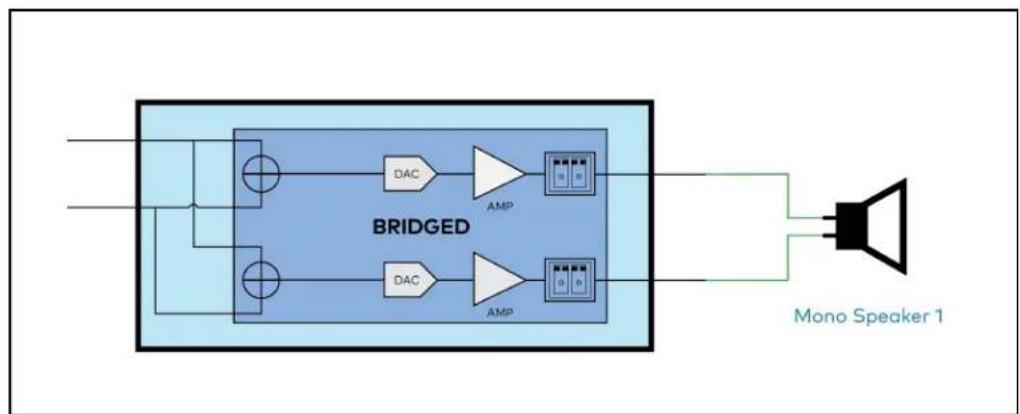
flowchart
graph LR
    A["Input"] --> B["BRIDGED"]
    B --> C["DAC"]
    B --> D["DAC"]
    B --> E["AMP"]
    B --> F["AMP"]
    B --> G["Ground"]
    H["Mono Speaker 1"] --> I["Output"]
Signal
![Signal [Autosaved] Signal Not Present Clipping None](/content/2026/05/985127/images/68e22be6bbc6f9a30f8f8f72d112494ef01ed463a1c739f151803b533c01744b.jpg)
The Signal section is a read-only field that displays the Signal and Clipping status of the zone output.
- If an output signal is present but not clipping, Signal will display Present in green and Clipping will display None in green.
- If an output signal is present and clipping, Signal will display Present in green and Clipping will display Present in red.
- If no output signal is detected, Signal will display Not Present in red and Clipping will display None in green.
Bussing Volume Offset

Bussing Volume Offset is an additional level compensation applied to the zone relative to any other zones it is grouped with via the Bussing feature.
To set the bussing volume offset, do one of the following:
- Move the Bussing Volume Offset slider to the right to increase or to the left to decrease the offset.
- Click the db arrows to increase or decrease the offset. Values range from -12 dB to 12 dB, adjustable in increments of 1 dB.
- Manually enter a value in the Bussing Volume Offset field.
Configure Speaker Profile
The DM-NAX-8ZSA has a library of built-in speaker profiles that contain equalizer, speaker protection, and impedance settings specific to Crestron and third-party speaker models. Custom speaker profiles can also be generated and loaded to the DM-NAX-8ZSA. The Configure Speaker Profile field is used to apply these speaker profiles to a given zone of the DM NAX device.
NOTE: Applying a speaker profile on a zone will overwrite the existing Speaker Configuration and Equalizer settings for that zone.

In the Global Filter field, enter the speaker's model name to search for its associated profile. Any speaker profiles matching the search criteria are displayed.
To apply a speaker profile:
-
Select the radio button corresponding to the speaker profile.
-
Click Apply.
The equalizer, impedance, and speaker protection settings of the zone are updated as per the applied speaker profile.
After applying a speaker profile, the Speaker Configuration and Equalizer settings for the zone can still be edited. The Configure Speaker Profile section will display a notification if these settings were altered after the speaker profile was applied.

Speaker Configuration

-
Set the Enable Speaker Protect toggle to the right position to enable speaker protection for the zone output. Set the toggle to the left position to disable speaker protection. By default, Enable Speaker Protect is set to the left position.
-
To set the maximum output wattage, do one of the following:
-
Move the Speaker Wattage slider to the right to increase or to the left to decrease the maximum peak amplifier wattage that can be output to the speaker.
- Click the Watts arrows to increase or decrease the maximum peak amplifier wattage that can be output to the speaker. Values range from 5 W to 150 W, adjustable in increments of 1 W.
-
Manually enter a value in the Speaker Wattage field.
-
Select the impedance of the speaker on a selected zone from the Impedance drop-down menu.
Values are 4 Ohms, 8 Ohms, and Bridged.
Casting
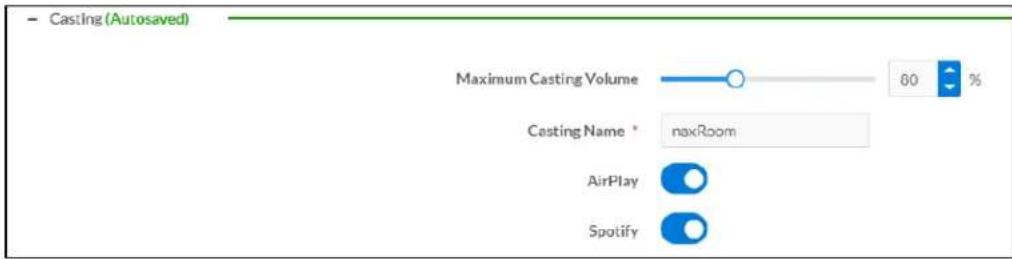
The Casting section is used to enable or disable the ability of third-party devices to cast audio to the DM NAX output zone, as well as set a maximum casting volume and friendly name for the zone.
To configure Casting:
- Maximum Casting Volume is an alternate value for the Maximum volume set in the
Minimum/Maximum Volume on page 214 settings, applied to the zone only when a casting service is routed to it. To set the maximum casting volume, do one of the following:
- Move the Maximum Casting Volume slider right to increase or left to decrease the maximum volume.
- Click the arrows to increase or decrease the maximum casting volume. Values range from 70% to 100%, adjustable in increments of 1%.
- Manually enter a value in the Maximum Casting Volume field.
NOTE: If the Maximum Casting Volume value is higher than the regular Maximum volume value, the Maximum value will be applied instead.
- A custom casting name (for example, "Living Room") must be entered so that a name for the zone will be displayed in the list of available casting destinations when initiating a stream. Enter this friendly name in the Casting Name field.
NOTE: Ensure that the Casting Name field is populated as any field with an asterisk (*) is mandatory.
Once AirPlay ^® and/or Spotify Connect ^™ are enabled, this name will be displayed as an available destination on the casting device.
To configure Apple AirPlay ^® casting:
- Set the AirPlay toggle to the right to enable AirPlay casting to the zone's associated media player. Set the AirPlay toggle to the left to disable AirPlay casting to the associated media player.
To configure Spotify Connect™ casting:
- Set the Spotify toggle to the right to enable Spotify Connect casting to the zone's associated media player. Set the Spotify toggle to the left to disable Spotify Connect casting to the associated media player.
To stream media from an iOS device or Spotify app to a zone in your distributed audio system, refer to the DM-NAX-8ZSA Quick Start.
To stream media from a Roon® streaming device to a zone in your distributed audio system:
-
Enable Apple AirPlay casting for each DM NAX zone.
-
Launch the Roon desktop app.
-
Open the Roon app menu and navigate to the Settings submenu, then select Audio. A table of discovered network devices that the Roon device can stream to will be displayed. Any devices that previously have been enabled for Roon casting are listed under the Connected to Core section, and the rest of the discovered devices are listed under Other network devices.
-
Find each of the DM NAX zones in the Other network devices list, then click the Enable button for each zone to connect it to the Roon Core® for casting.
-
Return to the Roon app home page and click on the speaker icon at the bottom right. Select a DM NAX zone from the list of available casting destinations. With a zone selected, start a media stream, and the Roon device will cast the streaming audio to the zone.
Speaker/Faults
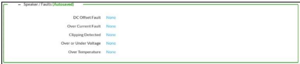
The Speaker/Faults section is a read-only field that displays the status of the DC Offset Fault, Over Current Fault, Clipping Detected, Over or Under Voltage, and Over Temperature detectors for the zone output. If clipping or a given fault type is detected, then its corresponding readout displays Fault Detected in red. Otherwise, it displays None in blue.
Line Out

Line Out Volume controls the volume level of the corresponding line-level output on the DM NAX device. This setting is only available on zones 1 through 4 of the DM-NAX-8ZSA, as zones 5 through 8 do not
have a corresponding line-level output. The Line Out Volume is only applied when Line Out EQ Bypass is enabled.
-
To set the line out volume, do one of the following:
-
Move the Line Out Volume slider to the right to increase or to the left to decrease the line out volume.
- Click the arrows to increase or decrease the line out volume. Values range from 0 to 100, adjustable in increments of 1. This range in dB is -80 dB to 20 dB.
-
Manually enter a value in the Line Out Volume field.
-
Set the Line Out EQ Bypass toggle to the right position to have the line-level output signal bypass the zone's equalizer settings. Set the toggle to the left position to have the line-level output signal pass through the zone's equalizer. By default, Line Out EQ Bypass is disabled.
NOTE: When the Line Out EQ Bypass setting is disabled, the line-level output's level will mirror the speaker output's Zone volume control. This allows for a variable signal level in applications where the line-level output is connected to an uncontrolled device such as powered speakers. If the Line Out EQ Bypass setting is enabled, the Line Out Volume slider can be used to set a fixed level for the line-level output. This level will not be affected by the speaker output Zone volume controls, so this configuration is better suited to applications where the line output is connected to a controlled amplifier with its own level adjustment.
Signal Generator

The DM-NAX-8ZSA has a built-in signal generator that allows an integrator to send an audio signal to any number of selected zones to test output functionality.
- To route the signal generator to the zone output, click the Signal Generator button so that it displays Active and is highlighted in blue. To unroute the signal generator on the zone output, click the Signal Generator button so that it displays Inactive and is highlighted in grey. By default, the signal generator is not routed to the zone output.
NOTES:
- There is only one signal generator built-in to the DM NAX device. Each zone has its own button to enable or disable the signal generator from passing signal to that output. Setting the signal generator to Inactive on a given zone output only breaks the route for that output and does not stop it from playing back in other zones.
-
The Signal Generator Volume control is a local control that does not affect the signal generator's volume on other zone outputs. Only the settings under Advanced Signal Generator are applied universally to all zones of the DM NAX device.
-
To adjust the signal generator's volume, do one of the following:
-
Move the Signal Generator Volume slider right to increase or left to decrease the volume.
- Click the arrows to increase or decrease the signal generator volume. Values range from 0 to 100, adjustable in increments of 1.
- Manually enter a value in the Signal Generator Volume field.
Advanced Signal Generator

The advanced signal generator settings control the built-in signal generator directly, and are applied universally to all output zones of the DM NAX device. The signal type for the generator can be set, and the left and right channels of the test signal can be individually enabled or disabled.
- Set the Left Channel toggle to the right position to enable the left channel of the signal. Set the toggle to the left position to disable the left channel. By default, Left Channel is enabled.
-
Set the Right Channel toggle to the right position to enable the right channel of the signal. Set the toggle to the left position to disable the right channel. By default, Right Channel is enabled.
-
Select an audio test signal type from the Signal Type drop-down menu. The available signal types are:
-
Tone: Generates a 1 kHz sine wave tone.
- Pink Noise: Generates pink noise.
- White Noise: Generates white noise.
Equalizer Settings
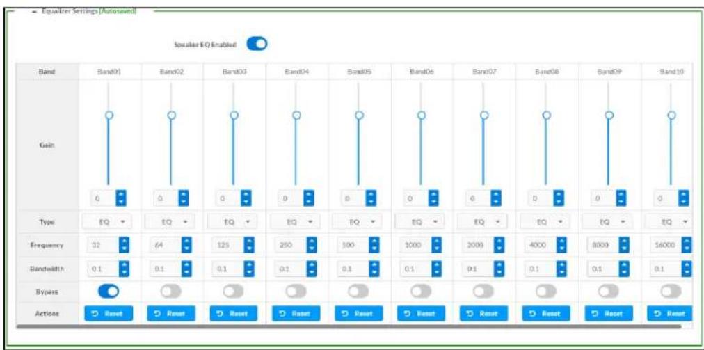
bar
| Band | Band01 | Band02 | Band03 | Band04 | Band05 | Band06 | Band07 | Band08 | Band09 | Band10 | |--------|--------|--------|--------|--------|--------|--------|--------|--------|--------|--------| | Gain | 0 | 0 | 0 | 0 | 0 | 0 | 0 | 0 | 0 | 0 | | Type | EQ | EQ | EQ | EQ | EQ | EQ | EQ | EQ | EQ | EQ | | Frequency | 32 | 64 | 125 | 250 | 500 | 1000 | 2000 | 4000 | 8000 | 16000 | | Bandwidth | 0.1 | 0.1 | 0.1 | 0.1 | 0.1 | 0.1 | 0.1 | 0.1 | 0.1 | 0.1 | | Bypass | Reset | Reset | Reset | Reset | Reset | Reset | Reset | Reset | Reset | Reset | | Actions| Reset | Reset | Reset | Reset | Reset | Reset | Reset | Reset | Reset | Reset |Each zone output of the DM-NAX-8ZSA has a dedicated ten-band equalizer that can be fully customized to tune the zone output signal to the needs of an install. Each band can have a discrete ga filter type, center frequency, and bandwidth set, and can also be bypassed. The equalizer itself can also be bypassed using the Speaker EQ Enabled toggle.
- Set the Speaker EQ Enabled toggle to the right position to enable the equalizer. Set the toggle to the left position to bypass the equalizer.
NOTE: When Speaker EQ Enabled is disabled, all equalizer bands are bypassed. This is a quick way to perform A/B testing of the entire EQ curve.
- With the Speaker EQ Enabled toggle in the right position, do the following to configure a given equalizer band:
a. To set a band's gain, do one of the following:
- Move the Gain slider up to increase or down to decrease the gain.
- Click the arrows to increase or decrease the gain. Values range from -40 dB to 20 dB, adjustable in increments of 0.1 dB.
- Manually enter a value in the Gain field.
b. Select a filter type from the Type drop-down menu. By default, all bands are set to the EQ filter type. Some filter types will disable other settings in their respective band while enabled. For example, selecting the LowPass filter type for a band will disable that band's Gain and Bandwidth settings, since the LowPass filter applies a fixed roll-off slope at a set frequency. The available filter types are:
- EQ: a fully parametric filter that can boost or cut a range of frequencies.
- Notch: a parametric filter designed to more precisely cut a frequency or range of frequencies. A notch filter can achieve a narrower bandwidth than the standard EQ parametric filter type.
- TrebleShelf: a filter that boosts or cuts all frequencies above a set frequency by a set gain.
- BassShelf: a filter that boosts or cuts all frequencies below a set frequency by a set gain.
- LowPass: a filter that fully cuts all frequencies above a set frequency using a fixed roll-off slope of -12 dB per octave.
- HighPass: a filter that fully cuts all frequencies below a set frequency using a fixed roll-off slope of -12 dB per octave.
c. Set a center frequency for the equalizer band to tune a specific portion of the audible frequency spectrum. To set the center frequency, do one of the following:
- Click the arrows to increase or decrease the frequency. Values range from 20 Hz to 20 kHz, adjustable in increments of 1 Hz. Each band has a default center frequency that will be applied if the Reset button at the bottom of the band is clicked.
- Manually enter a value in the Frequency field.
d. Set a bandwidth to determine how wide of a frequency range is effected by the equalizer band. To set the bandwidth, do one of the following:
- Click the arrows to increase or decrease the bandwidth. Values range from 0.1 octaves to 4.0 octaves, adjustable in increments of 0.1 octave.
- Manually enter a value in the Bandwidth field.
e. The individual Bypass controls allow you to bypass a single band of equalization at a time for more granular A/B testing of a single filter. Set a band's Bypass toggle to the right position to bypass that band. Set the toggle to the left position to disable the bypass. By default, Bypass is disabled.
f. Each equalizer band has a Reset button that will reapply the default settings for that band.
Click Done to return to the Settings tab of the web user interface.
Bussing
The bussing feature on DM NAX devices allows an integrator to assign any number of selected zones to a fixed group of zones (bus). Zones in a bus track the other zones' volume and routing. For example, when the source or volume for one zone in the bus is adjusted, all other zones in that bus receive the same adjustment. You can create up to four buses on the DM-NAX-8ZSA.

Configure Bussing
- If needed, enter a friendly name for each bus in its Name field.
- Select any number of zones from the Included Zones drop-down menu.
NOTE: Each zone can be a member of only one bus. Any zones that are already a member of another bus will not be shown in the Included Zones drop-down.
Inputs
The Inputs section is used to configure the Name, Compensation, and Mute attributes of the available analog, digital, and media streaming inputs on the DM-NAX-8ZSA.
A total of 16 inputs are available on the DM-NAX-8ZSA, including the 8 physical input connectors on the device's rear panel and the 8 internal media players used for media streaming services.

flowchart
graph TD
    A["Inputs"] --> B["Gain Label"]
    B --> C["TSOLIN01"]
    B --> D["TSOLIN02"]
    B --> E["S/PDIF1"]
    B --> F["S/PDIF2"]
    B --> G["RCA1"]
    B --> H["RCA2"]
    B --> I["RCA3"]
    B --> J["RCA4"]
    C --> K["Signal Present"]
    D --> L["Clipping Detected"]
    E --> M["Mute"]
    F --> N["Control buttons"]
    G --> O["Control buttons"]
    H --> P["Control buttons"]
    I --> Q["Control buttons"]
    J --> R["Control buttons"]
Configure Inputs
-
If needed, enter a friendly name for each input in its Name field.
-
To set a level compensation adjustment for a given input, do one of the following:
-
Move the Compensation slider up to increase or down to decrease the compensation. Compensation increases or decreases the level of the incoming audio signal on any of the physical inputs on the device's rear panel. Compensation is not available for any of the internal media players.
- Click the db arrows to increase or decrease the compensation. Values range from -10 dB to 10 dB, adjustable in increments of 1 dB.
-
Manually enter a value in the Compensation field.
-
To mute the signal from the corresponding input, click the Mute button. To disable the mute, click the Muted button. By default, Mute is disabled.
Monitor the device's input signals using the text indicators in the Signal Present and Clipping Detected columns:
- Signal Presence indicates whether or not a signal is detected in that zone.
- Clipping Detected indicates if the signal is Clipping or Nominal (non-clipping).
Use the Global Filter text field to filter specific inputs by name. Not all of the available inputs are shown on the first page in this section when no Global Filter is applied. Use ▶ at the bottom of the table to view the next page of inputs.
DM NAX Streams
Each local input of the DM-NAX-8ZSA can be made available as a DM NAX audio-over-IP stream. This includes the eight physical inputs on the rear panel of the device and the eight internal media players.
The DM-NAX-8ZSA also supports parallel DM NAX streams for each zone output, enabling an additional transmit stream per output to mirror all routes and DSP settings of its respective zone. These parallel
streams enable control of the audio signal to third-party uncontrolled AES67 devices receiving audio from the DM-NAX-8ZSA.
NOTES:
- Under the Transmitters section (see Configure Transmitters), the last four listed transmitters are dedicated to parallel zone outputs.
• To configure the DSP settings, see Zone Settings.
Click NAX Streams to expand the tab and display the following information.

- Device is Master PTP Clock Source indicates whether the DM NAX device's PTP clock is the master clock on the network. Yes will be displayed in green when the local DM-NAX-8ZSA's clock is the PTP master clock and No will be displayed in red when another PTP clock on the network is operating as the master clock.
- Master Clock Status displays the Master Clock ID of the device on the network that is currently acting as the master clock.
- PTP Priority: This sets the priority of the local DM NAX device's PTP clock relative to other clocks on the network. The default setting is 254 (one increment higher than the lowest possible value) so that the DM-NAX-8ZSA will only operate as clock master if no other PTP master is present on the network. Valid values range from 1 to 255.
Configure Transmitters
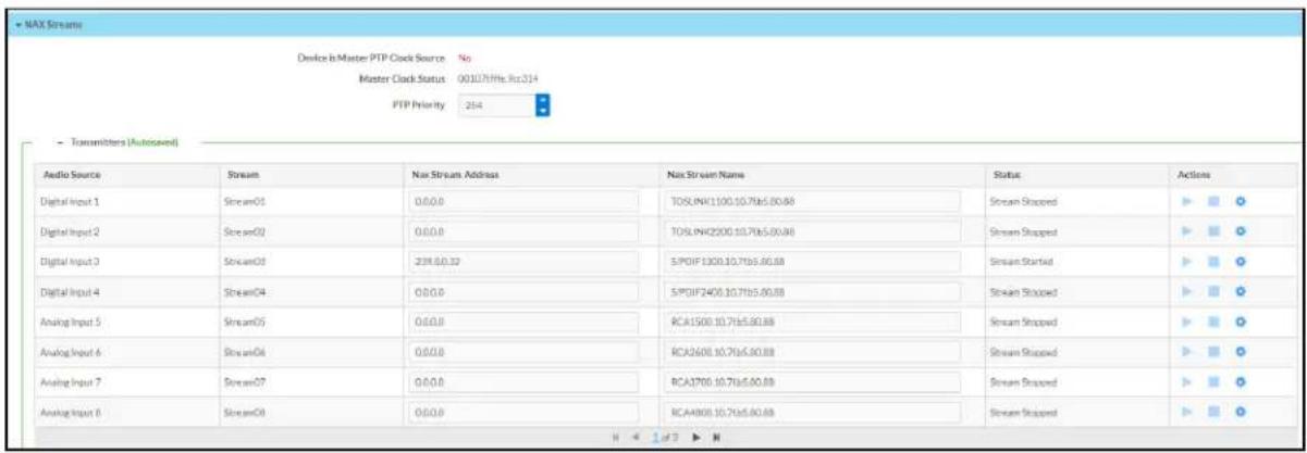
NOTE: To configure transmitters not shown on the current page of the table▶click the icon to display the next page of eight transmitters.
To configure a DM NAX transmit stream, do the following.
- Enter a valid multicast address in the NAX Stream Address field.
- Enter a name in the NAX Stream Name field by which the stream can be identified. This stream name is associated with the DM NAX stream's multicast address by other DM NAX or AES67 devices, like a device hostname that resolves to a given IP address.
- Status indicates whether a stream is transmitting or not. When the stream has started or stopped, the Status column will update accordingly.
- Click the configure button (💡) in the Actions column. The Configure dialog appears:

-
Set the Auto Initiation toggle to the right position to enable auto initiation. Set the toggle to the left position to disable auto initiation.
-
If Auto Initiation is enabled for a given stream, the stream will begin transmitting automatically and will be available as a multicast stream on your network at the specified multicast address.
-
If Auto Initiation is disabled for the input, the stream will not begin transmitting until it is manually initiated.
-
To set the port number, do one of the following:
-
Click the arrows to increase or decrease the port number by increments of 1.
-
Manually enter a port number in the Port field. The default port number for DM NAX streams is 5004.
-
Click OK to save or click Cancel to cancel the changes.
Configure Receivers
| - Recivers (Autosaved) | |||||
| Zone Name | Stream | Current Stream Address | Requested Stream Address | Status | Actions |
| Zone1 | Stream01 | 0:0:0.0 | 0:0:0.0 | Q Stream Stopped | ▶ ▶ ○ |
| Zone2 | Stream02 | 0:0:0.0 | 0:0:0.0 | Q Stream Stopped | ▶ ▶ ○ |
| Zone3 | Stream03 | 0:0:0.0 | 0:0:0.0 | Q Stream Stopped | ▶ ▶ ○ |
| Zone4 | Stream04 | 0:0:0.0 | 0:0:0.0 | Q Stream Stopped | ▶ ▶ ○ |
| Zone5 | Stream05 | 0:0:0.0 | 0:0:0.0 | Q Stream Stopped | ▶ ▶ ○ |
| Zone6 | Stream06 | 0:0:0.0 | 0:0:0.0 | Q Stream Stopped | ▶ ▶ ○ |
| Zone7 | Stream07 | 0:0:0.0 | 0:0:0.0 | Q Stream Stopped | ▶ ▶ ○ |
| Zone8 | Stream08 | 0:0:0.0 | 0:0:0.0 | Q Stream Stopped | ▶ ▶ ○ |
-
Enter the multicast address of a transmitting stream in the Requested Stream Address field to subscribe the receiver to the stream.
-
Click the configure button (💡) in the Actions column. The Configure dialog appears:

-
Set the Auto Initiation toggle to the right position to enable auto initiation. Set the toggle to the left position to disable auto initiation.
-
If Auto Initiation is enabled, the stream will begin automatically when the receiver subscribes to the transmitter.
-
If Auto Initiation is disabled, the stream will not begin until it is manually initiated.
-
To set the port number, do one of the following:
-
Click the arrows to increase or decrease the port number by increments of 1.
-
Manually enter a port number in the Port field. The default port number is 5004.
-
Click OK to save or click Cancel to cancel the changes.
Routing
The Routing section is used to route a local input, media player, or AES67 stream to a Zone on the DM-NAX-8ZSA.
NOTE: To receive an AES67 stream from Dante devices, see OLH 1001151.
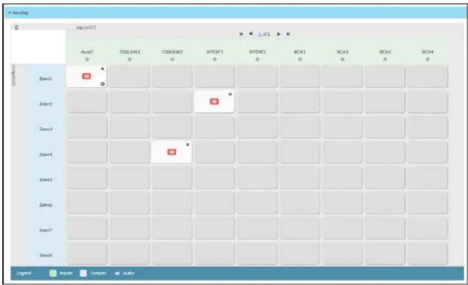
To route an input to a zone, click the box in the routing matrix where the zone's row overlaps the corresponding input's column. Once a route is made, appears. To break a given route click or . To route a single input to all zones, click on the icon under the input's name.
Use the arrows◀ or ▶ at the top of the matrix to change pages to view all available inputs.
To select a specific DM NAX/AES67 stream when AES67 is selected as the source for a Zone, do the following:
- Click to display the list of all DM NAX/AES67 streams discovered on the network and click a radio button to select the corresponding stream to be routed to the zone.
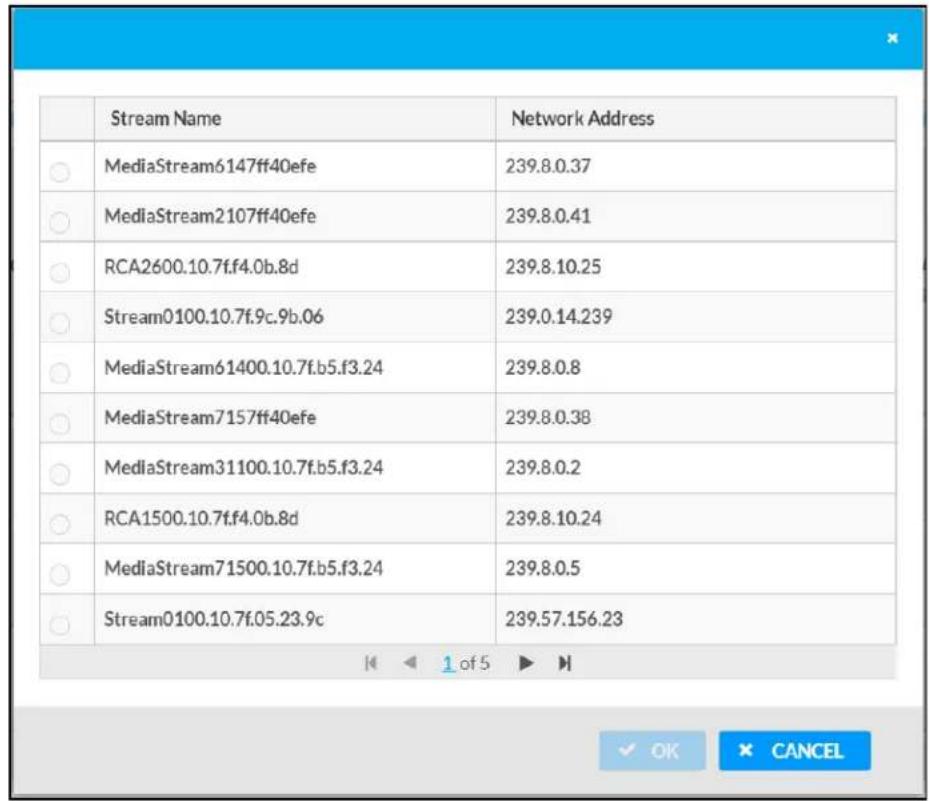
- Click OK to save or click Cancel to cancel the changes.
Streaming Services
The DM-NAX-8ZSA features eight built-in media streaming players, each of which can play back a discrete media stream from a cloud-based service or local casting device. User Profiles can be created for each user of the DM NAX device with discrete credentials, enabling multiple users access to media streaming services without interfering with other users' recommendations, favorites, or playlists.

To configure Streaming Services:
- Click the + Add User Profile button to create a new user profile. Each user profile can contain a unique set of accounts for all supported streaming services.
- Enter a name in the Profile Name field. Click Save to create the User Profile. Once the profile is created, you have the option to either Delete the profile, or add Services to it.
- Click Services in the Action column and an Edit Services window appears.
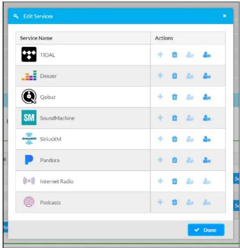
- Select from the available Streaming Services: TIDAL™, Deezer®, Qobuz®, SOUNDMACHINE®, SiriusXM®, Pandora®, Internet Radio, and Podcasts. Click + or 📋 to add or delete the desired streaming services for each user profile.
User Authentication
User authentication is required for TIDAL, Deezer, Qobuz, SOUNDMACHINE, SiriusXM and Pandora. Click to authorize the user.
To authenticate SiriusXM streaming:
NOTE: To determine whether to use commercial accounts, refer to the streaming service license agreement or FAQs on their respective portals. For SiriusXM, click here.
Enter the user credentials and click OK.

To authenticate TIDAL streaming:
- Click on the link to log in to the TIDAL portal.
NOTE: The link is valid for one minute. After one minute, the link expires, and the Authorize URL is shown as blank. The Authorize User dialogue will need to be closed and reopened.

- Click DONE to return to Streaming Services.
To authenticate Deezer streaming:
- Click on the link to log in to the Deezer portal.
NOTE: The link is valid for one minute. After one minute, the link expires, and the Authorize URL is shown as blank. The Authorize User dialogue will need to be closed and reopened.

- Click DONE to return to Streaming Services.
To authenticate Qobuz streaming:
- Click on the link to log in to the Qobuz portal.
NOTE: The link is valid for one minute. After one minute, the link expires, and the Authorize URL is shown as blank. The Authorize User dialogue will need to be closed and reopened.

- Click DONE to return to Streaming Services.
To authenticate SOUNDMACHINE streaming:
NOTE: To determine whether to use commercial accounts, refer to the streaming service license agreement or FAQs on their respective portals. For SOUNDMACHINE, click here.

- Click the link to log in to the SOUNDMACHINE portal.
NOTE: The link is valid for one minute. After one minute, the link expires, and the Authorize URL is shown as blank. The Authorize User dialogue will need to be closed and reopened.
- Log in to the SOUNDMACHINE account.
- Click DONE to return to Streaming Services.
To authenticate Pandora streaming:

- Click the icon to copy the activation code.
- Click the link to register the device. The Device Activation page is displayed.
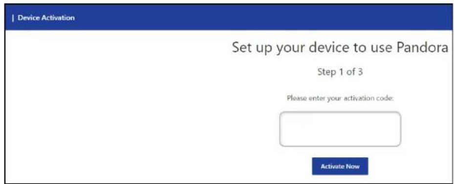
NOTE: The link is valid for one minute. After one minute, the link expires, and the Authorize URL and Enter Code are shown as blank. The Authorize User dialogue will need to be closed and reopened.
- Paste the activation code in the Please enter your activation code field and click Activate Now.
- Log in to the Pandora account.
- Click DONE to return to Streaming Services.
Port Selection
The Port Selection feature allows the device's internal network traffic to be managed and segregated based on traffic type. Internal VLANs are used to segment device management and streaming service traffic to a separate physical device Ethernet port than audio-over-IP streaming traffic. With Port Selection enabled on all DM NAX devices on a network, DM NAX and AES67 network traffic can be physically separated from the control network onto a dedicated audio network.

To configure Port Selection:
- Set the Port Selection toggle to the right position to enable Port Selection. Set the toggle to the left position to disable Port Selection. By default, Port Selection is disabled.
NOTE: Ports 1 and 2 correspond to the Ethernet adapters labeled 1 and 2 on the rear panel of the DM-NAX-8ZSA, respectively.
- With Port Selection enabled, select an Ethernet port from the Management drop-down menu to designate which Ethernet port on the rear panel of the device will handle network traffic relating to device configuration, streaming services, and the device's connection to a control system.
NOTES:
- To access streaming services, the Management port must be connected to a network with internet access.
-
The Management port determines your connection to the web interface. Changing the port value can result in losing your connection to the device via the web interface.
-
With Port Selection enabled, select an Ethernet port from the Audio/NAX drop-down menu to designate which Ethernet port on the rear panel of the device will handle audio-over-IP streaming network traffic.
-
Click Save changes to apply the new settings.
NOTE: Making changes to Port Selection settings will require a reboot.
Security
Click the Security tab to configure security for users and groups and to allow different levels of access to the DM-NAX-8ZSA functions. By default, security is disabled.

Select Encrypt and Validate, Encrypt, or OFF in the SSL Mode drop-down menu, to specify whether to use encryption. By default, SSL Mode is set to OFF.
Current User
Click the Current User tab to view read-only information or to change the password for the current user.
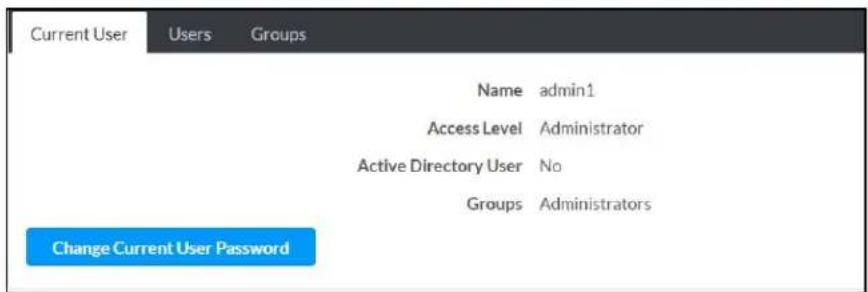
- Click the Change Current User Password button to provide a new password for the current user.
- In the Change Password dialog, enter the current password in the Current Password field, the new password in the Password field, and then re-enter the same new password in the Confirm Password field.
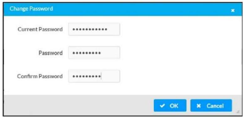
- Click OK to save or click Cancel to cancel the changes.
Users
Click the Users tab to view and edit user settings. The Users tab can be used to add or remove local and Active Directory users and preview information about users.
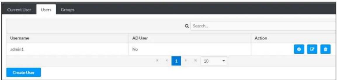
Use the Search Users field to enter search term(s) and display users that match the search criteria.
If users listed in the Users table span across multiple pages, navigate through the list of users by clicking a page number or by using the left or right arrows at the bottom of the Users pane to move forward or backward through the pages.
Each page can be set to display 5, 10, or 20 users by using the drop-down menu to the right of the navigation arrows.
Information about existing users is displayed in table format and the following details are provided for each user.
- Username: Displays the name of the user.
- AD User: Displays whether the user requires authentication using Active Directory.
Click the corresponding button in the Actions column to view detailed user information or to delete the user.
To create a new user, click the Create User button.
Create a New Local User
-
Click the Create User button in the User tab.
-
In the Create User dialog, enter the following:

a. Enter a user name in the Name field. A valid user name can consist of alphanumeric characters (letters a-z, A-Z, numbers 0-9) and the underscore "_" character.
b. Enter a password in the Password field; re-enter the same password in the Confirm Password field.
c. Assign the access level by selecting one or more groups from the Groups drop-down list.
NOTE: Make sure that the Active Directory User toggle is disabled.
- Click OK to save or click Cancel to cancel the changes.
Add an Active Directory User
Users cannot be created or removed from the Active Directory server, but access can be granted to an existing user in the Active Directory server.
To grant access to an Active Directory user, you can either add the user to a local group on the DM-NAX-8ZSA, or add the Active Directory group(s) that they are a member of to the DM-NAX-8ZSA.
To add an Active Directory user.
- Click the Create User button.
- In the Create User dialog, enter the following.

a. Enter a user name in the Name field in the format "Domain\UserName", for example "crestronlabs.com\JohnSmith". Valid user names can contain alphanumeric characters (letters a-z, A-Z, numbers 0-9) and the underscore "_" character.
b. Select one or more groups from the Groups drop-down list.
NOTE: Make sure that the Active Directory User toggle is set to enabled.
- Click OK to save or click Cancel to cancel the changes.
Delete User
Click the trashcan button (☐) in the Actions column to delete the user. Click Yes when prompted to delete the user or No to cancel the deletion.
After a user is removed from a group, they lose any access rights associated with that group. Note that the user account is not deleted by the delete user operation.
View User Details
Click the information button (0) in the Actions column to view information for the selected user. The User Details dialog displays the following information for the selected user.
- Name: Displays the name of the selected user.
• Active Directory User: Displays whether the user is an Active Directory user. - Group: Displays group(s) the selected user is part of.
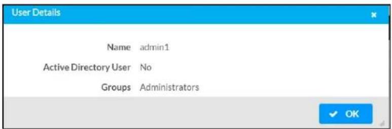
Click OK to close the User Details dialog and to return to the Users tab.
Update User Details

- Click the edit button() in the Actions column to update information for the selected user.
- Enter a password in the Password field; re-enter the same password in the Confirm Password field.
- Select one or more groups to assign the user to from the Groups drop-down list.
- Click OK to save or click Cancel to cancel the changes.
The Update User dialog also displays the following read-only information for the selected user.
• Name: Displays the name of the user.
• Active Directory User: Displays whether the user is an Active Directory user.
Groups
Click the Groups tab to view and edit group settings. The Groups tab can be used to add local and Active Directory groups, remove local and Active Directory groups, and preview information about a group.
Use the Search Groups field to enter search term(s) and display groups that match the search criteria.
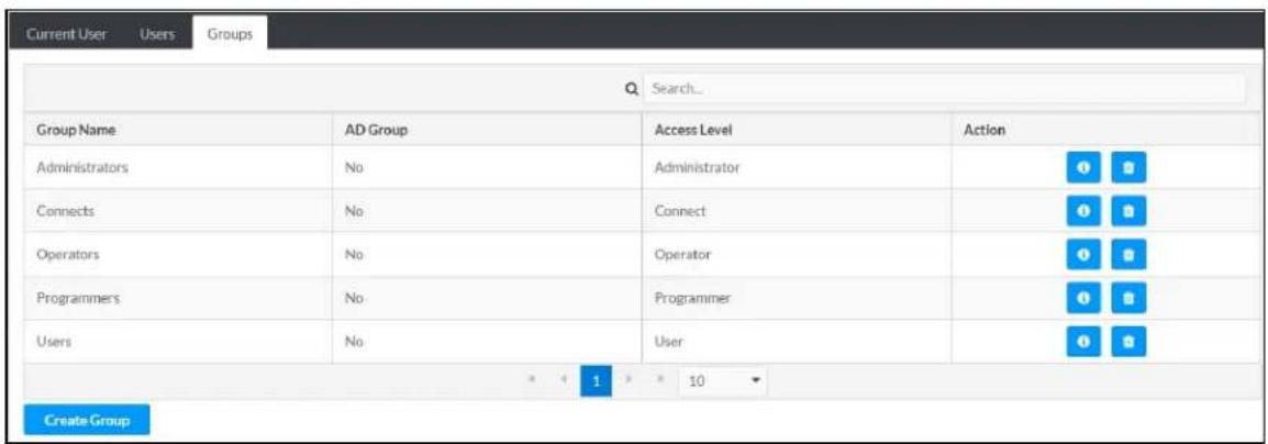
If groups listed in the Groups table span across multiple pages, navigate through the groups by clicking a page number or by using the left or right arrows at the bottom of the Groups pane to move forward or backward through the pages.
Additionally, each page can be set to display 5, 10, or 20 groups by using the drop-down menu to the right of the navigation arrows.
Existing groups are displayed in a table and the following information is provided for each group:
- Group Name: Displays the name of the group.
- AD Group: Displays whether the group requires authentication using Active Directory.
- Access Level: Displays the predefined access level assigned to the group (Administrator, Programmer, Operator, User, or Connect).
Click the corresponding button in the Actions column to view detailed group information (☐) or to delete ☐ selected group.
Click on the Create Group button in the Groups tab to create new group.
Create Local Group

- Click the Create Group button.
- In the Create Group dialog, enter the following:
a. Enter the group name in the Name field.
b. Assign the group access level by selecting a predefined access level (Administrator, Connect, Operator, Programmer, User) from the Access Level drop-down list.
NOTE: Make sure that the Active Directory Group toggle is disabled.
- Click OK to save. Click Cancel to cancel the changes.
Add Active Directory Group
A group cannot be created or removed from the Active Directory server, but access can be granted to a existing group in Active Directory.
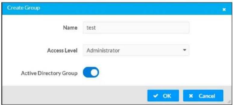
Once the group is added, all members of that group will have access to the DM-NAX-8ZSA.
- Click the Create Group button.
- In the Create Group dialog enter the following:
a. Enter the group name in the Name field, for example "Engineering Group". Note that group names are case sensitive; a space is a valid character that can be used in group names.
- Assign the group access level by selecting a predefined access level (Administrator, Connect, Operator, Programmer, User) from the Access Level drop-down list.
NOTE: Make sure that the Active Directory Group toggle is enabled.
- Click OK to save. Click Cancel to cancel the changes.
Delete a Group
Click the trashcan button (☐) in the Actions column to delete a group. Click Yes when prompted to delete the group or No to cancel the deletion.
When a group is deleted, users in the group are not removed from the device or Active Directory server. However, because a user's access level is inherited from a group(s), users within the deleted group will lose access rights associated with the group.
View Group Details
Click the information button (6) in the Actions column to view information for the selected group. The Group Details dialog lists the following information for the selected group.
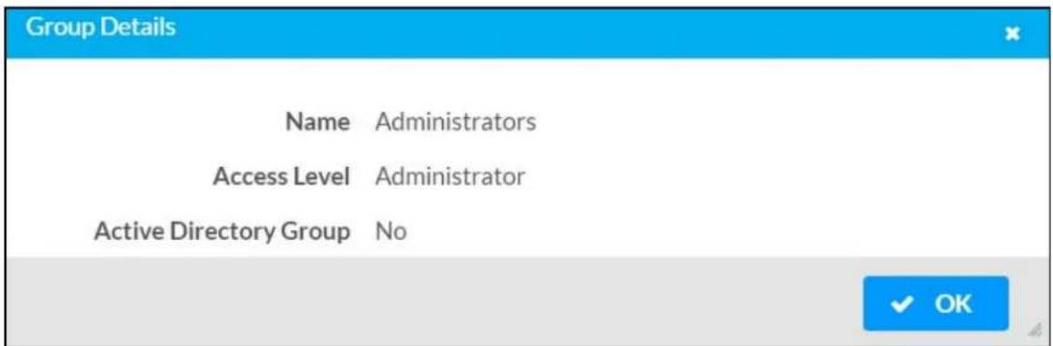
• Name: Displays the name of the group.
- Access Level: Displays the access level of the group and its users.
• Active Directory Group: Displays whether the group is an Active Directory group.
Click OK to close the Group Details dialog and to return to the Groups tab.
802.1x Configuration
The DM-NAX-8ZSA has built-in support for the 802.1X standard (an IEEE network standard designed to enhance the security of wireless and Ethernet LANs. The standard relies on the exchange of messages between the device and the network's host, or authentication server), allowing communication with the authentication server and access to protected corporate networks.

To Configure DM-NAX-8ZSA for 802.1X Authentication
- Set the IEEE 802.1X Authentication toggle to enabled. This will enable all options on the 802.1X dialog.
-
Select the Authentication method: EAP-TLS Certificate or EAP-MSCHAP V2 Password according to the network administrator's requirement.
-
Do either one of the following:
-
Select EAP-TLS Certificate, click Action/Manage Certificates to upload the required machine certificate. The machine certificate is an encrypted file that will be supplied by the network administrator, along with the certificate password.
-
Select EAP-MSCHAP V2 Password, enter the username and password supplied by the network administrator into the Username and Password fields. This method does not require the use of a machine certificate, only the user name and password credentials.
-
If you enabled the Enable Authentication Server Validation option, this will enable the Select Trusted Certificate Authoritie(s) list box which contains signed Trusted Certificate Authorities (CAs) preloaded into the DM-NAX-8ZSA.
Select the check box next to each CA whose certificate can be used for server validation, as specified by the network administrator.
If the network does not use any of the listed certificates, the network administrator must provide a certificate, which must be uploaded manually via the Manage Certificates functionality.
-
If required, type the domain name of the network in the Domain field.
-
When the 802.1X settings are configured as desired, click Save Changes to save the changes to the device and reboot it. Click Revert to cancel any changes.
Access the Web Interface With the Crestron Toolbox Application
To access the web interface by opening a web browser within the Crestron Toolbox™ application, do the following:
-
Open the Crestron Toolbox application.
-
From the Tools menu, select Device Discovery Tool. You can also access the Device Discovery Tool by clicking the Device Discovery Tool button ( ) in the Crestron Toolbox toolbar. The DM-NAX-2XLRI-1G is discovered and listed in the device list on the left side of the screen. The associated host name, IP address, and firmware version are also displayed.
NOTE: If there is security software running on the computer, a security alert might be displayed when the Crestron Toolbox application attempts to connect to the network. Make sure to allow the connection, so that the Device Discovery Tool can be used.
-
In the Device Discovery Tool list, double-click your device.
-
Enter your credentials in the Authentication Required dialog that opens, and then click Log In.
-
Click the Web Configuration button in the Configuration page displayed on the left side of the Device Discovery Tool.
DM-NAX-4ZSA-50
This section describes how to configure the DM-NAX-4ZSA-50.
Web Interface Configuration
The DM-NAX-2XLRI-1G web interface allows you to view status information and configure network and device settings.
Access the Web Interface
To access the web interface, do either of the following:
- Access the Web Interface with a Web Browser on page 257
- Access the Web Interface With the Crestron Toolbox™ Application on page 313
The web interface is accessed from a web browser. The following table lists operating systems and their corresponding supported web browsers.
Operating System and Supported Web Browsers
| OPERATING SYSTEM SUPPORTED WEB BROWSERS | |
| Windows® operating system | ChromeTM web browser, version 31 and laterFirefox® web browser, version 31 and laterInternet Explorer web browser, version 11 and laterMicrosoft Edge web browser |
| macOS® operating system | Safari® web browser, version 6 and laterChrome web browser, version 31 and laterFirefox web browser, version 31 and later |
Access the Web Interface with a Web Browser
- Enter the IP address of the DM-NAX-4ZSA-50 into a web browser.
NOTE: To obtain the IP address, use the Device Discovery Tool option in Crestron Toolbox™ application or an IP scanner application.
- If you are creating a user account for the first time, do the following; otherwise, skip to step 3.
a. Enter a username in the Username field.
b. Enter a password in the Password field.
c. Re-enter the same password in the Confirm Password field.

d. Click Create User. The Device Administration page appears.
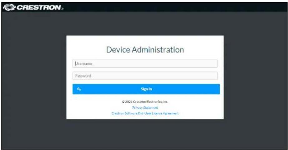
- Enter the username in the Username field.
- Enter the password in the Password field.
- Click Sign In.
Action
The Action drop-down menu is displayed at the top right side of the interface and provides quick access to common device functions:
- Save Changes
- Revert
- Reboot
- Restore
- Update Firmware
- Download Logs
- Manage Certificates
- Manage Audio Profiles
- Download Configuration
- Upload Configuration
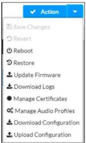
Save Changes
Click Save Changes to save any changes made to the configuration settings.
Revert
Click Revert to revert the device back to the last saved configuration settings.
Reboot the DM-NAX-4ZSA-50
Certain changes to the settings may require the DM-NAX-4ZSA-50 to be rebooted to take effect. To reboot the device, do the following:
- Click Reboot in the Actions drop-down menu. The Confirmation message box appears.
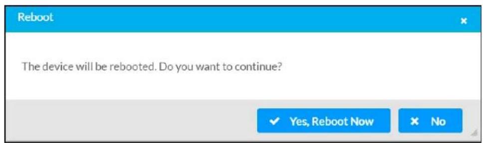
- Click Yes, Reboot Now to reboot the device. The Reboot message box appears.
Wait for the device reboot to complete before attempting to reconnect to the device.
Restore to Factory Default Settings
- Click Restore in the Actions drop-down menu to restore the settings of the DM-NAX-4ZSA-50 to factory defaults.
NOTE: When settings are restored, all settings, including the network settings, will revert to the factory default. If a static IP address is set, restoring the device to factory default settings will revert the IP address to the default DHCP mode.
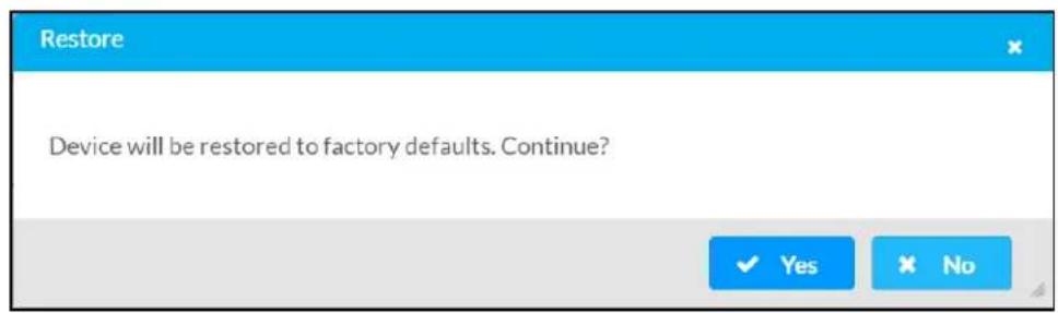
- Click Yes in the Confirmation dialog to restore the DM-NAX-4ZSA-50 to factory settings. Click No to cancel the restore operation.
A dialog is displayed again, indicating that the restore process was successful and that the device rebooted.
You can also restore to factory settings by pressing and holding the SETUP button on the rear panel of the device with power disconnected then connect the power supply and continue to hold SETUP button for 30 seconds.
Update Firmware
-
Click Update Firmware in the Actions drop-down menu.
-
In the Firmware Upgrade dialog, click + Browse.

-
Locate and select the desired firmware file, and then click Open. The selected firmware file name is displayed in the Firmware Upgrade dialog.
-
Click Load and wait for the progress bar to complete and for the OK button in the message to become clickable.
-
Click OK. The device with new firmware can now be accessed.
Download Logs
- Click Download Logs in the Actions drop-down menu to download the device message logs for diagnostic purposes.
The log file is downloaded to the Downloads folder of the PC.
Manage Certificates
Use the Manage Certificates dialog to add, remove, and manage certificates used in 802.1x and other protected networks.
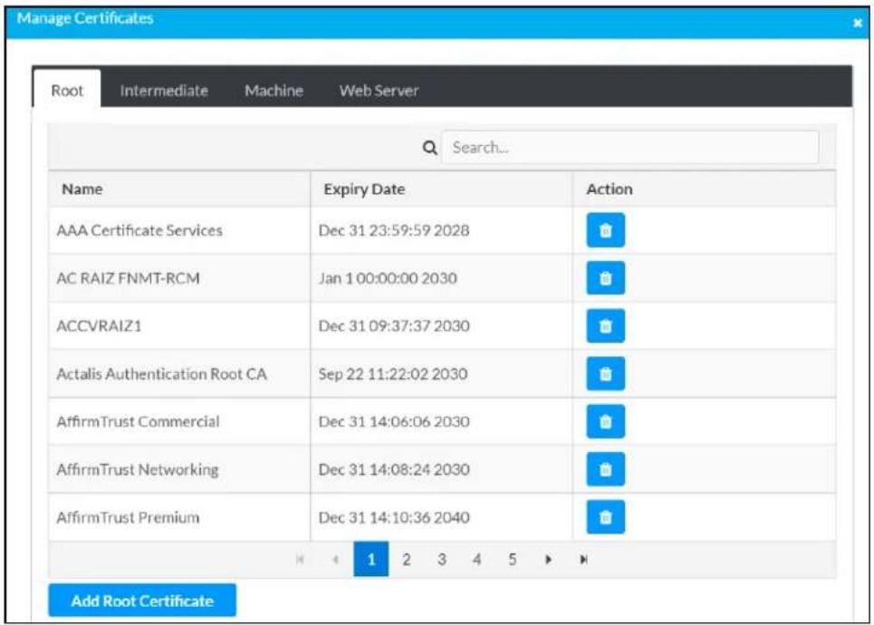
-
Click Manage Certificates in the Actions drop-down menu. The following certificate tabs are displayed:
-
Root: The Root certificate is used by the DM-NAX-4ZSA-50 to validate the network's authentication server. The DM-NAX-4ZSA-50 has a variety of Root certificates, self-signed by trusted CAs (Certificate Authorities) preloaded into the device. Root certificates must be self-signed.
- Intermediate: The Intermediate store holds non self-signed certificates that are used to validate the authentication server. These certificates will be provided by the network administrator if the network does not use self-signed Root certificates.
- Machine: The machine certificate is an encrypted PFX file that is used by the authentication server to validate the identity of the DM-NAX-4ZSA-50. The machine certificate will be provided by the network administrator, along with the certificate password. For 802.1x, only one machine certificate can reside on the device.
- Web Server: The Web Server certificate is a digital file that contains information about the identity of the web server.
To Add Certificates
- Click the corresponding certificate tab.
- Click the Add Root Certificate button.
- Click the + Browse button.
- Locate and select the file, and then click the Open button.
NOTE: If the certificate is a Machine Certificate, enter the password provided by the network administrator.
- Click OK. This will add the certificate to the list box, displaying the file name and expiration date.
The certificate is now available for selection and can be loaded to the device.
To Delete Certificates
- Click the corresponding certificate tab.
- Click the trashcan button ( ) in the Actions column to delete the certificate.
- Click Yes when prompted to delete the certificate or No to cancel the deletion.
Manage Audio Profiles
Use the Manage Audio Profiles dialog to add, remove, and manage the audio profiles of speakers.

Click Manage Audio Profiles in the Actions drop-down menu. The following audio profiles tabs are displayed, providing information such as Model, Manufacturer, and Type of the speaker profiles:
- Default Profiles: Lists the default library of included speaker profiles.
- User Profiles: Lists the custom, user loaded profiles, and allows them to be loaded and removed.
In the Search field, enter the speaker's profile name to search for the profile. The speaker profile matching the search criteria is displayed.
NOTE: To create a custom speaker profile, see OLH 1001820.
To Add a Speaker Profile
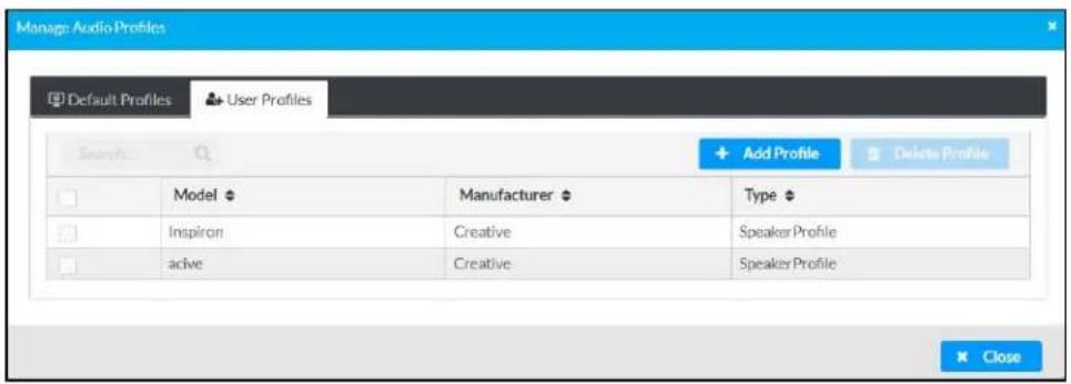
- Click the User Profiles tab.
- Click the + Add Profiles button.
- Click the + Browse button.
- Locate and select the .prof file, and then click the Open button.
- Click the Upload button.
- Click OK. This will add the profile to the list box.
The speaker profile is now available for selection and can be applied to the speaker.
To Delete a Speaker Profile
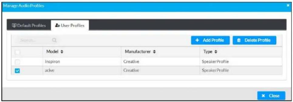
- Click the User Profiles tab.
- Select the checkbox corresponding to the audio profile that needs to be deleted.
- Click Delete Profile button.
The speaker profile is deleted.
Download Configuration
Click Download Configuration to download a TGZ file containing the settings data for the DM NAX device.
NOTE: User accounts for accessing the device, streaming service accounts, multicast addresses, and stream names are not saved in this configuration file.
Upload Configuration
- Click Upload Configuration to upload a TGZ file that will overwrite the current settings of the DM NAX device with a saved configuration.
CAUTION: Be sure to load a TGZ file for the same DM NAX device type while using the Load Configuration feature. For example, if loading a TGZ file to a DM-NAX-4ZSA-50, be sure that the TGZ file originated from a DM-NAX-4ZSA-50.
- Click Browse to navigate to the desired TGZ file in your file browser. Double-click the file or highlight it and click Open.

-
Click Upload to begin the file upload process. A progress bar will indicate the status of the configuration file upload.
-
Once the upload is complete, the device will require a reboot. Click Yes, Reboot Now to begin the reboot, or click No to return to the web UI.

NOTE: Any changes made after the configuration file upload, but before a device reboot, may be overwritten when the device is rebooted.
Status
The Status tab is the first page displayed when opening the interface of the DM-NAX-4ZSA-50. It displays general information about the DM-NAX-4ZSA-50 (such as Model Name, Firmware Version, and Serial Number), current network settings (such as Host Name and IP Address, etc.), and input and output ports' current status.
The Status tab can be accessed at any time by clicking the Status tab of the DM-NAX-4ZSA-50 interface.
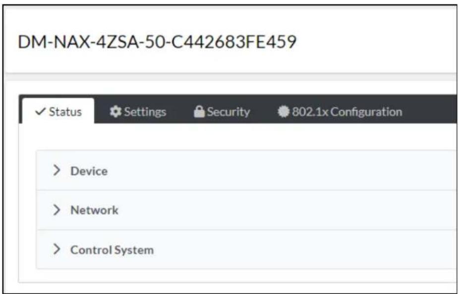
Information displayed on the Status tab is organized into different sections.
Device
The Device section displays the Model, Firmware Version, and Serial Number of the DM-NAX-4ZSA-50.
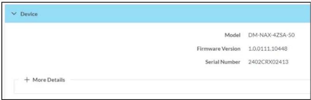
Click + More Details to review additional information about the DM-NAX-4ZSA-50.
![Mora Details DM-NAX-4ZSA-50 1.0.0111.10448 Build Feb 16 2024(531614) Updater 1.0.0111.10448 Bootloader 02.019.000 CCUI Version 1.1338.557 XIOSDK 3.8.2 IoTSDK 1.10.1 Build time 10:44:52 Product ID 0x7A04 Revision ID 0xC300 HDCP2X-SKE HDCP2X-SKE HDCP2X-SKE [v9.0000.00000,#FFFFFFFFF] PRE-BOOT [v9.0000.00000] BOOTLOADER [v9.0000.00000] amp0-fuga-4zsa FW v551.39 Rev.17 (Driver v1.1) ctrl-audio-dsp-0 FW v19 (Driver v4.00) ctrl-prod-info Driver v3.0 PUF 1.0.0111.10448 Forced Auth Mode True](/content/2026/05/985127/images/3f241cea7f14558593c654b10840c56166d646070ed072afb22e669c090d1986.jpg)
Network
The Network section displays network-related information about the DM-NAX-4ZSA-50, including the Hostname, Domain Name, and DNS Servers.

NOTE: By default, the host name of the DM-NAX-4ZSA-50 consists of the model name followed by the MAC address of the device. For example, DM-NAX-4ZSA-50-00107FB58088.
Click + Adapter 1 to display an expanded section that shows additional information. If + Adapter 1 is selected, click - Less details to collapse the section.
NOTE: The + Adapter 2 option appears when the dual Ethernet ports on the DM-NAX-4ZSA-50 are set to isolate traffic using the Port Selection feature.
Control System
The Control System section displays connection information, consisting of the following:
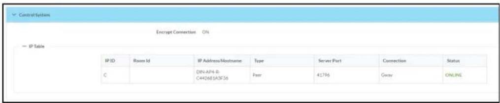
- Encrypt Connection: ON or OFF
• IP ID: Reports the currently used IP ID of the DM-NAX-4ZSA-50 - IP Address/Hostname: The IP address of the control system
• Room ID: Displays the room ID
• Status: OFFLINE or ONLINE
Settings
The Settings tab enables you to configure the DM-NAX-4ZSA-50 settings. The Settings page can be accessed at any time by clicking the Settings tab of the DM-NAX-4ZSA-50 interface.
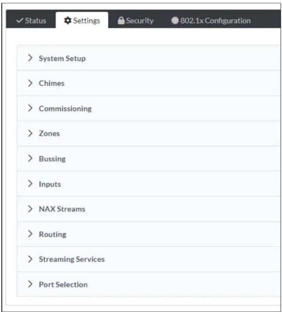
Settings available on the Settings tab are organized into different sections.
System Setup
The System Setup section contains settings for Date/Time, Auto Update, Network, and Control System.
Date/Time
Use the Date/Time section to configure the date and time settings of the DM-NAX-4ZSA-50.

Time Synchronization
- Set the Time Synchronization toggle to the right position to enable or left position to disable time synchronization. By default, time synchronization is enabled.
- In the NTP Time Servers table, enter the URL of a NTP (Network Time Protocol) or SNTP (Simple Network Time Protocol) server. Up to three time servers can be added on a device.
- Click Synchronize Now to perform time synchronization between the device's internal clock and the time server.
Time Configuration
- Click on the Time Zone drop-down menu to select the applicable time zone.
- In the Date field, enter the current date.
- In the Time (24hr Format) field, enter the current time in 24-hour format.
Click the Save Changes button to save the settings.
Click Revert from the Actions drop-down menu to revert to the previous settings without saving.
Auto Update
The DM-NAX-4ZSA-50 can automatically check for and install firmware updates at scheduled intervals via the Auto Update feature.
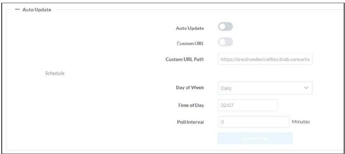
-
Set the Auto Update toggle to the right position to enable Auto Update.
-
Define the URL to download the updates by doing either of the following:
a. Use the default URL to download the updates from the Crestron server.
b. Use a custom URL. Set the Custom URL toggle to the right position to enable a custom URL. In the Custom URL Path text box, enter the path to a custom manifest file in the F or SFTP URL format. Use the Crestron Auto Update Tool to generate a custom manifest file, then store the file on an FTP (File Transfer Protocol) or SFTP (Secure File Transfer Protocol) server.
- Set a schedule for the automatic firmware update by doing either of the following:
a. Select the desired Day of Week and Time of Day (24-hour format) values.
b. Set the Poll Interval by entering a value from 60 to 65535 minutes. A value of 0 disables the Poll Interval.
- Click Save Changes.
Clicking Update Now causes the device to check for a firmware update immediately. If a schedule was set in step 4 above, that schedule still remains in effect.
Network
The Network section contains network-related settings for the DM-NAX-4ZSA-50, including the Hostname, Domain, Primary Static DNS, and Secondary Static DNS.

NOTE: By default, the hostname of the DM-NAX-4ZSA-50 consists of the model name followed by the MAC address of the device. For example, DM-NAX-4ZSA-50-00107FB58088.
Adapter 1
The Adapter 1 subheading contains settings for DHCP, IP Address, Subnet Mask, and Default Gateway of Ethernet adapter 1 on the rear panel of the device.
NOTES:
- An + Adapter 2 option only appears when the dual Ethernet ports on the DM-NAX-4ZSA-50 are set to isolate traffic using the Port Selection feature. The settings for Adapter 2 are identical to those available for Adapter 1.
- DM NAX devices' internal processes use IP addresses in the 10x10 range. This IP range should be avoided when addressing DM NAX devices to prevent conflicts.
Set the DHCP toggle to enabled (right) or disabled (left) to specify whether the IP address of the DM-NAX-4ZSA-50 is to be assigned by a DHCP (Dynamic Host Configuration Protocol) server.
- Enabled: When DHCP is enabled (default setting), the IP address of the DM-NAX-4ZSA-50 is automatically assigned by a DHCP server on the local area network (LAN).
-
Disabled: When DHCP is disabled, manually enter information in the following fields:
-
Primary Static DNS: Enter a primary DNS IP address.
Secondary Static DNS: Enter a secondary DNS IP address.
IP Address: Enter a unique IP address for the DM-NAX-4ZSA-50. - Subnet Mask: Enter the subnet mask that is set on the network.
Default Gateway: Enter the IP address that is to be used as the network's gateway.
To save any new network entries, click Save Changes.
Control System
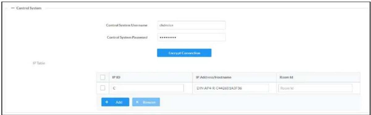
- Click the Encrypt Connection button to navigate to the Security tab to configure encryption settings.
- Enter the username in the Control System Username field.
- Enter the password in the Control System Password field.
- Enter the Room ID in the Room ID field.
- Enter the IP ID of the DM-NAX-4ZSA-50 in the IP ID field.
- Enter the IP address or hostname of the control system in the IP Address/Hostname field.
- Click the Save Changes button to save the new entries. The Control System Save message box appears, indicating that the control system settings were saved successfully. Click the Revert button to revert to the previous settings without saving.
Commissioning
The Commissioning section provides a quick way to automatically assign multicast addresses to all of the device's internal audio-over-IP stream transmitters.
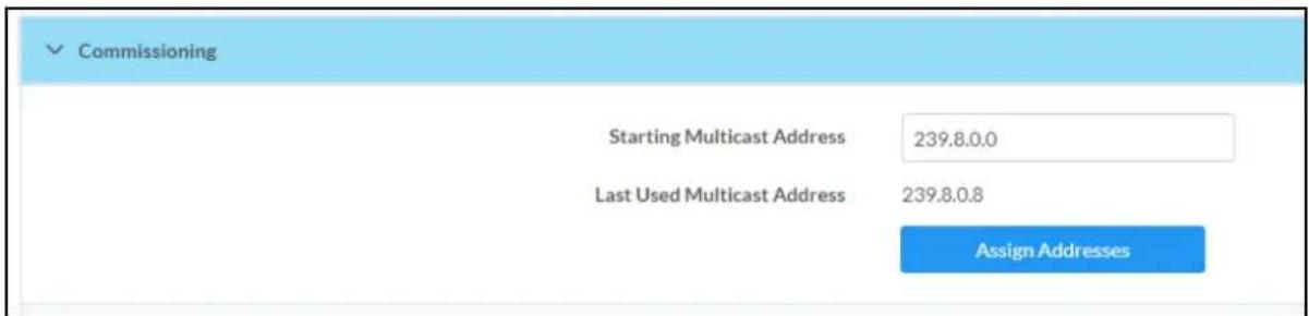
Click Assign Addresses to give each DM NAX transmitter in the DM-NAX-4ZSA-50 a unique multicast address beginning with the specified Starting Multicast Address. The valid range for Starting Multicast Address is 239.8.0.0 to 239.255.255.247.
NOTE: This will begin transmitting multicast traffic on your network, refer to the DM NAX Audio-over-IP System Design Guide document for details.
Chimes
The Chimes section allows the built-in chime files to be assigned to any of the output zones on the device.

For each chime file, click the cells corresponding to the desired Zones for playback of that specific chime sound. You can assign multiple chimes to the same zone. To view all available chimes, use the or arrows at the left of the matrix to change pages.
To configure the chime volume of a zone:
- Click the icon corresponding to the zone. A Configure window appears.
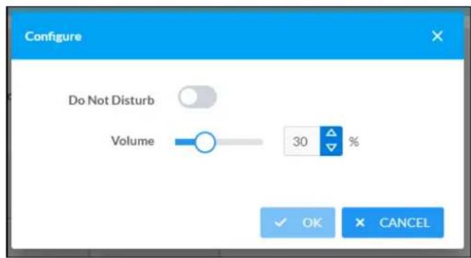
-
To set the volume, do one of the following:
-
Move the Volume slider to the right to increase or to the left to decrease the chime volume
- Click the % arrows to increase or decrease the chime volume. Values range from 0 to 100%, adjustable in increments of 1%.
- Manually enter a value in the Volume field.
NOTE: The chime volume is independent of the zone volume control.
-
Set the Do Not Disturb toggle to the right to mute all chimes for the zone. Set the Do Not Disturb toggle to the left to unmute the chimes.
-
Click OK to apply the new settings.
Zones
The Zones section contains the Volume and Mute settings for all zone outputs of the device, as well as a Configure option for more advanced settings within each zone.
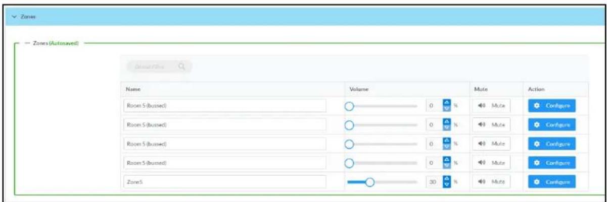
Give each zone a friendly name using the Name column of the Zones table. If the device is paired with a control system, these names may be overwritten by the control system's program.
To configure the zone volume, do one of the following:
- Move the Volume slider to the right to increase or to the left to decrease the zone volume.
- Click the % arrows to increase or decrease the zone volume. Values range from 0 to 100%, adjustable in increments of 1%.
- Manually enter a value in the Volume field.
To mute all audio output from a zone, click its respective Mute button. To unmute the zone, click the Muted button.
Zone Settings
To configure zone settings, click the Configure button (Configure). The Edit Zone window appears.

Zone
Click Zone to access the settings for Tone, Balance, and Delay.

Tone

The Tone section provides adjustments for the Tone Profile, Bass, Treble, Loudness, and Night Mode settings of the zone output.
NOTE: The Tone Profile, Bass, Treble, and Loudness settings in the Tone section are all applied separately from the Equalizer Settings for the zone. This means that any adjustments made in the Tone section will stack with those made in the Equalizer Settings section.
- To select a tone profile preset for the zone, select an option from the Tone Profile drop-down menu. The available options are Off, Classical, Jazz, Pop, Rock, and Spoken Word. By default, Off is selected.
-
Bass: To adjust the bass, do one of the following:
-
Move the Bass slider to the right to increase or to the left to decrease the bass.
- Click the db arrows to increase or decrease the db. Values range from -12 db to 12 db, adjustable in increments of 1 db.
-
Manually enter a value in the Bass field.
-
Treble: To adjust the treble, do one of the following:
-
Move the Treble slider to the right to increase or to the left to decrease the treble.
- Click the db arrows to increase or decrease the db. Values range from -12 db to 12 db, adjustable in increments of 1 db.
-
Manually enter a value in the Treble field.
-
To enable the loudness setting on the zone output, slide the Loudness switch to the right. To disable loudness, slide the Loudness switch to the left.
-
The Night Mode feature applies subtle processing to restrict the dynamic range of the zone audio, to allow for lower listening levels at night or in rooms where higher listening levels would be disruptive. To select a dynamics processing level, select an option from the Night Mode drop-down menu. The available options are Off, Low, Medium, and High. By default, Off is selected.
Balance

To adjust the left/right balance of the stereo output signal, do one of the following:
- Move the Balance slider to the right to shift the stereo balance to the right channel or to the left to shift the balance to the left.
- Click the arrows to adjust the balance left or right. The up arrow shifts the balance to the right while the down arrow shifts the balance to the left.
- Manually enter a value in the Balance field. Values range from -50 to 50, adjustable in increments of 1. Positive values shift the balance to the right while negative values shift the balance to the left.
Delay

To set the delay, do one of the following:
- Move the Delay Time(ms) slider to the right to increase or to the left to decrease the delay time.
- Click the ms arrows to increase or decrease the delay. Values range from 0 ms to 250 ms, adjustable in increments of 1 ms.
- Manually enter a value in the Delay Time(ms) field.
Output
Click Output to access the settings for Minimum/Maximum Volume, Stereo/Mono, Signal, Bussing Volume Offset, Configure Speaker Profile, Speaker Configuration, Casting, Speaker/Faults, Line Out, Signal Generator, Advanced Signal Generator, and Equalizer Settings.

Minimum/Maximum Volume

-
To set the minimum volume of the zone, do one of the following:
-
Move the Minimum slider to the right to increase or to the left to decrease the minimum volume.
- Click the % arrows to increase or decrease the minimum volume. Values range from 0 to 50%, adjustable in increments of 1%.
-
Manually enter a value in the Minimum field.
-
To set the maximum volume of the zone, do one of the following:
-
Move the Maximum slider to the right to increase or to the left to decrease the maximum volume.
- Click the % arrows to increase or decrease the maximum volume. Values range from 70 to 100%, adjustable in increments of 1%.
- Manually enter a value in the Maximum field.
NOTE: When a Minimum and Maximum volume are set, the 1-100% range represented by the Zone and Default volume controls are scaled to the range set. For example, if a Minimum of 10% and a Maximum of 80% are set for a zone, the 1-100% range of the Zone volume control is scaled to the 10%-80% range set as the Minimum and Maximum.
-
To set the default volume of the zone, do one of the following:
-
Move the Default slider to the right to increase or to the left to decrease the default volume.
- Click the % arrows to increase or decrease the default volume. Values range from 0 to 50% adjustable in increments of 1%.
- Manually enter a value in the Default field.
NOTE: The Default volume is applied as the Zone volume any time the zone receives a source route and no source was previously routed to that zone.
Stereo/Mono

- Select either Stereo or Mono from the Stereo/Mono field.
Stereo
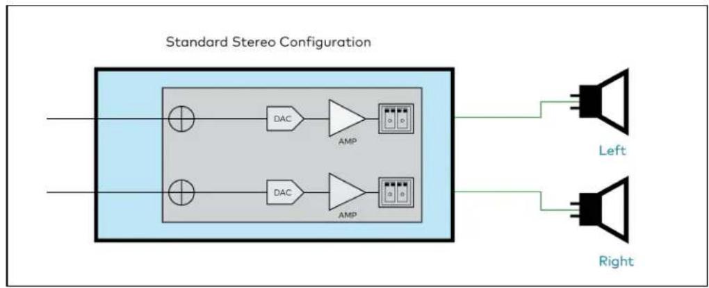
flowchart
graph LR
    A["Input"] --> B["DAC"]
    B --> C["AMP"]
    C --> D["Left Speaker"]
    C --> E["Right Speaker"]
    F["Input"] --> G["DAC"]
    G --> H["AMP"]
    H --> I["Left Speaker"]
    H --> J["Right Speaker"]
Mono

flowchart
graph LR
    A["Input"] --> B["Block with DAC and AMP"]
    B --> C["AMP Stage"]
    B --> D["DAC Stage"]
    D --> E["Output"]
    F["Mono Speaker 1"] --> G["Speaker"]
    H["Mono Speaker 2"] --> I["Speaker"]
NOTE: The signal flow diagrams above are specifically for the speaker output zones (Zones 1 through 4). The diagrams still apply for Zone 5 with the exception of the amplifiers shown in the path of each output channel.
Signal

The Signal section is a read-only field that displays the Signal and Clipping status of the zone output.
- If an output signal is present but not clipping, Signal will display Present in green and Clipping will display None in green.
- If an output signal is present and clipping, Signal will display Present in green and Clipping will display Present in red.
- If no output signal is detected, Signal will display Not Present in red and Clipping will display None in green.
Bussing Volume Offset

Bussing Volume Offset is an additional level compensation applied to the zone relative to any other zones it is grouped with via the Bussing feature.
To set the bussing volume offset, do one of the following:
- Move the Bussing Volume Offset slider to the right to increase or to the left to decrease the offset.
- Click the db arrows to increase or decrease the offset. Values range from -12 dB to 12 dB, adjustable in increments of 1 dB.
- Manually enter a value in the Bussing Volume Offset field.
Configure Speaker Profile
The DM-NAX-4ZSA-50 has a library of built-in speaker profiles that contain equalizer, speaker protection, and impedance settings specific to Crestron and third-party speaker models. Custom speaker profiles can also be generated and loaded to the DM-NAX-4ZSA-50. The Configure Speaker Profile field is used to apply these speaker profiles to a given zone of the DM NAX device.
NOTE: Applying a speaker profile on a zone will overwrite the existing Speaker Configuration and Equalizer settings for that zone.

In the Global Filter field, enter the speaker's model name to search for its associated profile. Any speaker profiles matching the search criteria are displayed.
To apply a speaker profile:
-
Select the radio button corresponding to the speaker profile.
-
Click Apply.
The equalizer, impedance, and speaker protection settings of the zone are updated as per the applied speaker profile.
NOTE: Zone 5 does not have impedance or speaker protection settings, but speaker profiles can still be applied to the zone output. Only the equalizer settings are effected when a speaker profile is applied to Zone 5.
After applying a speaker profile, the Speaker Configuration and Equalizer settings for the zone can still be edited. The Configure Speaker Profile section will display a notification if these settings were altered after the speaker profile was applied.

Profile settings have been locally altered
Speaker Configuration (Zones 1 through 4 only)

-
Set the Enable Speaker Protect toggle to the right position to enable speaker protection for the zone output. Set the toggle to the left position to disable speaker protection. By default, Enable Speaker Protect is set to the left position.
-
To set the maximum output wattage, do one of the following:
-
Move the Speaker Wattage slider to the right to increase or to the left to decrease the maximum peak amplifier wattage that can be output to the speaker.
- Click the Watts arrows to increase or decrease the maximum peak amplifier wattage that can be output to the speaker. Values range from 5 W to 150 W, adjustable in increments of 1 W.
-
Manually enter a value in the Speaker Wattage field.
-
Select the impedance of the speaker on a selected zone from the Impedance drop-down menu. Values are 4 Ohms, 8 Ohms, and Bridged.
Casting

The Casting section is used to enable or disable the ability of third-party devices to cast audio to the DM NAX output zone, as well as set a maximum casting volume and friendly name for the zone.
To configure Casting:
- Maximum Casting Volume is an alternate value for the Maximum volume set in the
Minimum/Maximum Volume on page 278 settings, applied to the zone only when a casting service is routed to it. To set the maximum casting volume, do one of the following:
- Move the Maximum Casting Volume slider right to increase or left to decrease the maximum volume.
- Click the arrows to increase or decrease the maximum casting volume. Values range from 70% to 100%, adjustable in increments of 1%.
- Manually enter a value in the Maximum Casting Volume field.
NOTE: If the Maximum Casting Volume value is higher than the regular Maximum volume value, the Maximum value will be applied instead.
- A custom casting name (for example, "Living Room") must be entered so that a name for the zone will be displayed in the list of available casting destinations when initiating a stream. Enter this friendly name in the Casting Name field.
NOTE: Ensure that the Casting Name field is populated as any field with an asterisk (*) is mandatory.
Once Spotify Connect™ is enabled, this name will be displayed as an available destination on the casting device.
The DM-NAX-4ZSA-50 supports Spotify Connect™ casting.
To stream media to a zone on the DM-NAX-4ZSA-50 via Spotify Connect casting:
- Ensure that the casting device and DM-NAX-4ZSA-50 are on the same network.
NOTE: If Port Selection is enabled on the DM-NAX-4ZSA-50, Spotify Connect will use the port specified for Control/Media traffic.
-
Set the Spotify Connect toggle to the right to enable Spotify Connect casting to the zone's associated media player.
-
On the casting device:
a. Open the Spotify application.
b. Enable Spotify Connect casting.
c. From the list of available casting destinations, select the DM-NAX-4ZSA-50 media player you would like to stream to. The device will cast the streaming audio to the selected media player.
NOTE: By default, media players 1-5 route to their respectively numbered output zones 1-5 if they are not already routed to any other zones when casting playback begins. For example, the audio from the media player 5 will be routed to output zone 5 if an AirPlay casting session on media player 5 starts and it is not already routed to another zone.
d. After the Spotify Connect stream begins, control the volume of the streaming DM-NAX-4ZSA-50 output zone directly from the Spotify application on the casting device.
Set the Spotify Connect toggle to the left to disable Spotify Connect casting for a DM-NAX-4ZSA-50 media player.
Speaker/Faults

The Speaker/Faults section is a read-only field that displays the status of the DC Offset Fault, Over Current Fault, Clipping Detected, Over or Under Voltage, and Over Temperature detectors for the zone output. If clipping or a given fault type is detected, then its corresponding readout displays Fault Detected in red. Otherwise, it displays None in blue.
Signal Generator

The DM-NAX-4ZSA-50 has a built-in signal generator that allows an integrator to send an audio signal to any number of selected zones to test output functionality.
- To route the signal generator to the zone output, click the Signal Generator button so that it displays Active and is highlighted in blue. To unroute the signal generator on the zone output, click the Signal Generator button so that it displays Inactive and is highlighted in grey. By default, the signal generator is not routed to the zone output.
NOTES:
- There is only one signal generator built-in to the DM NAX device. Each zone has its own button to enable or disable the signal generator from passing signal to that output. Setting the signal generator to Inactive on a given zone output only breaks the route for that output and does not stop it from playing back in other zones.
-
The Signal Generator Volume control is a local control that does not affect the signal generator's volume on other zone outputs. Only the settings under Advanced Signal Generator are applied universally to all zones of the DM NAX device.
-
To adjust the signal generator's volume, do one of the following:
-
Move the Signal Generator Volume slider right to increase or left to decrease the volume.
- Click the arrows to increase or decrease the signal generator volume. Values range from 0 to 100, adjustable in increments of 1.
- Manually enter a value in the Signal Generator Volume field.
Advanced Signal Generator

The advanced signal generator settings control the built-in signal generator directly, and are applied universally to all output zones of the DM NAX device. The signal type for the generator can be set, and the left and right channels of the test signal can be individually enabled or disabled.
- Set the Left Channel toggle to the right position to enable the left channel of the signal. Set the toggle to the left position to disable the left channel. By default, Left Channel is enabled.
- Set the Right Channel toggle to the right position to enable the right channel of the signal. Set the toggle to the left position to disable the right channel. By default, Right Channel is enabled.
-
Select an audio test signal type from the Signal Type drop-down menu. The available signal types are:
-
Tone: Generates a 1 kHz sine wave tone.
- Pink Noise: Generates pink noise.
- White Noise: Generates white noise.
Equalizer Settings
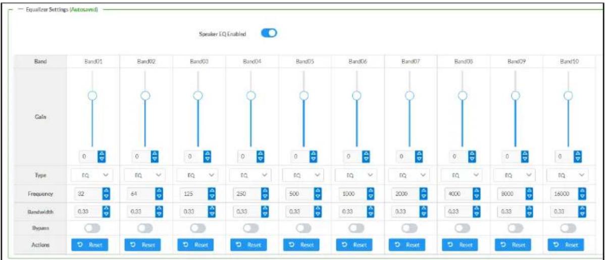
bar
| Band | Band01 | Band02 | Band03 | Band04 | Band05 | Band06 | Band07 | Band08 | Band09 | Band10 | |--------|--------|--------|--------|--------|--------|--------|--------|--------|--------|--------| | Gain | 0 | 0 | 0 | 0 | 0 | 0 | 0 | 0 | 0 | 0 | | Type | EQ | EQ | EQ | EQ | EQ | EQ | EQ | EQ | EQ | EQ | | Frequency | 32 | 64 | 125 | 250 | 500 | 1000 | 2000 | 4000 | 8000 | 16000 | | Bandwidth | 0.33 | 0.33 | 0.33 | 0.33 | 0.33 | 0.33 | 0.33 | 0.33 | 0.33 | 0.33 | | Bypass | Reset | Reset | Reset | Reset | Reset | Reset | Reset | Reset | Reset | Reset | | Actions| Reset | Reset | Reset | Reset | Reset | Reset | Reset | Reset | Reset | Reset |Each zone output of the DM-NAX-4ZSA-50 has a dedicated ten-band equalizer that can be fully customized to tune the zone output signal to the needs of an install. Each band can have a discrete ga filter type, center frequency, and bandwidth set, and can also be bypassed. The equalizer itself can also be bypassed using the Speaker EQ Enabled toggle.
- Set the Speaker EQ Enabled toggle to the right position to enable the equalizer. Set the toggle to the left position to bypass the equalizer.
NOTE: When Speaker EQ Enabled is disabled, all equalizer bands are bypassed. This is a quick way to perform A/B testing of the entire EQ curve.
- With the Speaker EQ Enabled toggle in the right position, do the following to configure a given equalizer band:
a. To set a band's gain, do one of the following:
- Move the Gain slider up to increase or down to decrease the gain.
- Click the arrows to increase or decrease the gain. Values range from -40 dB to 20 dB, adjustable in increments of 0.1 dB.
- Manually enter a value in the Gain field.
b. Select a filter type from the Type drop-down menu. By default, all bands are set to the EQ filter type. Some filter types will disable other settings in their respective band while enabled. For example, selecting the LowPass filter type for a band will disable that band's Gain and Bandwidth settings, since the LowPass filter applies a fixed roll-off slope at a set frequency. The available filter types are:
- EQ: a fully parametric filter that can boost or cut a range of frequencies.
- Notch: a parametric filter designed to more precisely cut a frequency or range of frequencies. A notch filter can achieve a narrower bandwidth than the standard EQ parametric filter type.
- TrebleShelf: a filter that boosts or cuts all frequencies above a set frequency by a set gain.
- BassShelf: a filter that boosts or cuts all frequencies below a set frequency by a set gain.
- LowPass: a filter that fully cuts all frequencies above a set frequency using a fixed roll-off slope of -12 dB per octave.
- HighPass: a filter that fully cuts all frequencies below a set frequency using a fixed roll-off slope of -12 dB per octave.
c. Set a center frequency for the equalizer band to tune a specific portion of the audible frequency spectrum. To set the center frequency, do one of the following:
- Click the arrows to increase or decrease the frequency. Values range from 20 Hz to 20 kHz, adjustable in increments of 1 Hz. Each band has a default center frequency that will be applied if the Reset button at the bottom of the band is clicked.
- Manually enter a value in the Frequency field.
d. Set a bandwidth to determine how wide of a frequency range is effected by the equalizer band. To set the bandwidth, do one of the following:
- Click the arrows to increase or decrease the bandwidth. Values range from 0.1 octaves to 4.0 octaves, adjustable in increments of 0.1 octave.
- Manually enter a value in the Bandwidth field.
e. The individual Bypass controls allow you to bypass a single band of equalization at a time for more granular A/B testing of a single filter. Set a band's Bypass toggle to the right position to bypass that band. Set the toggle to the left position to disable the bypass. By default, Bypass is disabled.
f. Each equalizer band has a Reset button that will reapply the default settings for that band.
Click Done to return to the Settings tab of the web user interface.
Bussing
The bussing feature on DM NAX devices allows an integrator to assign any number of selected zones to a fixed group of zones (bus). Zones in a bus track the other zones' volume and routing. For example, when the source or volume for one zone in the bus is adjusted, all other zones in that bus receive the same adjustment. You can create up to two buses on the DM-NAX-4ZSA-50.
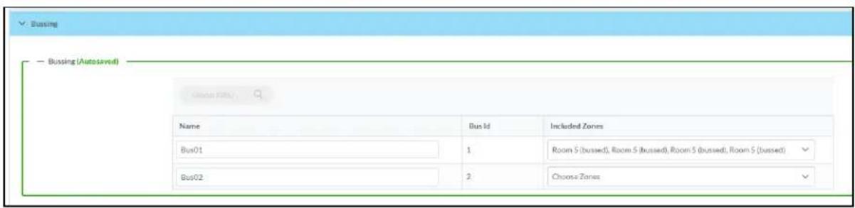
Configure Bussing
- If needed, enter a friendly name for each bus in its Name field.
- Select any number of zones from the Included Zones drop-down menu.
NOTE: Each zone can be a member of only one bus. Any zones that are already a member of another bus will not be shown in the Included Zones drop-down.
Inputs
The Inputs section is used to configure the Name, Compensation, and Mute attributes of the available analog and digital inputs on the DM-NAX-4ZSA-50.
A total of 9 inputs are available on the DM-NAX-4ZSA-50, including the 4 physical input connectors on the device's rear panel and the 5 internal media players used for media streaming services. Only the attributes of the 4 physical inputs can be adjusted in the Inputs section.

Configure Inputs
- If needed, enter a friendly name for each input in its Name field.
- To set a level compensation adjustment for a given input, do one of the following:
- Move the Gain slider up to increase or down to decrease the level compensation.
Compensation increases or decreases the level of the incoming audio signal on any of the physical inputs on the device's rear panel.
- Click the db arrows to increase or decrease the compensation. Values range from -10 dB to 10 dB, adjustable in increments of 1 dB.
-
Manually enter a value in the Gain field.
-
To mute the signal from the corresponding input, click the Mute button. To disable the mute, click the Muted button. By default, Mute is disabled.
Monitor the device's input signals using the text indicators in the Signal Present and Clipping Detected columns:
• Signal Presence indicates whether or not a signal is detected in that zone.
- Clipping Detected indicates if the signal is Clipping or Nominal (non-clipping).
DM NAX Streams
Each local input of the DM-NAX-4ZSA-50 can be made available as a DM NAX audio-over-IP stream. This includes the four physical inputs on the rear panel of the device and the five internal media players Click NAX Streams to expand the tab and display the following information.

- Device is Master PTP Clock Source indicates whether the DM NAX device's PTP clock is the master clock on the network. Yes will be displayed in green when the local DM-NAX-4ZSA-50's clock is the PTP master clock and No will be displayed in red when another PTP clock on the network is operating as the master clock.
- Master Clock Status displays the Master Clock ID of the device on the network that is currently acting as the master clock.
- PTP Priority: This sets the priority of the local DM NAX device's PTP clock relative to other clocks on the network. The default setting is 254 (one increment higher than the lowest possible value) so that the DM-NAX-4ZSA-50 will only operate as clock master if no other PTP master is present on the network. Valid values range from 1 to 255.
Configure Transmitters

NOTE: To configure transmitters not shown on the current page of the table▶click the icon to display the next page of transmitters.
To configure a DM NAX transmit stream, do the following.
- Enter a valid multicast address in the NAX Stream Address field.
- Enter a name in the NAX Stream Name field by which the stream can be identified. This stream name is associated with the DM NAX stream's multicast address by other DM NAX or AES67 devices, like a device hostname that resolves to a given IP address.
- Status indicates whether a stream is transmitting or not. When the stream has started or stopped, the Status column will update accordingly.
- Click the configure button (⚙️) in the Actions column. The Configure dialog appears:
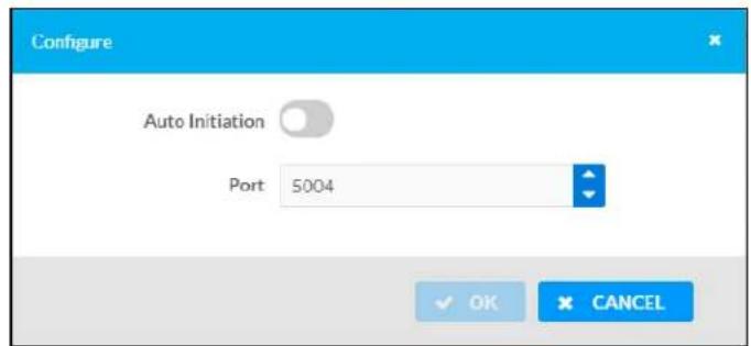
-
Set the Auto Initiation toggle to the right position to enable auto initiation. Set the toggle to the left position to disable auto initiation.
-
If Auto Initiation is enabled for a given stream, the stream will begin transmitting automatically and will be available as a multicast stream on your network at the specified multicast address.
-
If Auto Initiation is disabled for the input, the stream will not begin transmitting until it is manually initiated.
-
To set the port number, do one of the following:
-
Click the arrows to increase or decrease the port number by increments of 1.
-
Manually enter a port number in the Port field. The default port number for DM NAX streams is 5004.
-
Click OK to save or click Cancel to cancel the changes.
Configure Receivers
| Zone Name | Stream | Current Stream Address | Requested Stream Address | Status | Actions | |
| Room 3 (busted) | StreamO1 | 0.0.0.0 | 0.0.0.0 | Q | Stream Stopped | |
| Room 9 (busted) | StreamO2 | 0.0.0.0 | 0.0.0.0 | Q | Stream Stopped | |
| Room 5 (busted) | StreamO3 | 0.0.0.0 | 0.0.0.0 | Q | Stream Stopped | |
| Room 5 (busted) | StreamO4 | 0.0.0.0 | 0.0.0.0 | Q | Stream Stopped | |
| Zone5 | StreamO5 | 0.0.0.0 | 0.0.0.0 | Q | Stream Stopped | |
- Enter the multicast address of a transmitting stream in the Requested Stream Address field to subscribe the receiver to the stream.
- Click the configure button (💡) in the Actions column. The Configure dialog appears:
-
Set the Auto Initiation toggle to the right position to enable auto initiation. Set the toggle to the left position to disable auto initiation.
-
If Auto Initiation is enabled, the stream will begin automatically when the receiver subscribes to the transmitter.
-
If Auto Initiation is disabled, the stream will not begin until it is manually initiated.
-
To set the port number, do one of the following:
-
Click the arrows to increase or decrease the port number by increments of 1.
-
Manually enter a port number in the Port field. The default port number is 5004.
-
Click OK to save or click Cancel to cancel the changes.
Routing
The Routing section is used to route a local input, media player, or AES67 stream to a Zone on the DM-NAX-4ZSA-50.
NOTE: To receive an AES67 stream from Dante devices, see OLH 1001151.

To route an input to a zone, click the box in the routing matrix where the zone's row overlaps the corresponding input's column. Once a route is made, appears. To break a given route click or . To route a single input to all zones, click on the icon under the input's name.
Use the arrows ◀ or ▶ at the top of the matrix to change pages to view all available inputs.
To select a specific DM NAX/AES67 stream when AES67 is selected as the source for a Zone, do the following:
- Click to display the list of all DM NAX/AES67 streams discovered on the network and click a radio button to select the corresponding stream to be routed to the zone.

- Click OK to save or click Cancel to cancel the changes.
Streaming Services
The DM-NAX-4ZSA-50 features five built-in media streaming players, each of which can play back a discrete media stream from a cloud-based service or local casting device. User Profiles can be created for each user of the DM NAX device with discrete credentials, enabling multiple users access to media streaming services without interfering with other users' recommendations, favorites, or playlists.

To configure Streaming Services:
- Click the + Add User Profile button to create a new user profile. Each user profile can contain a unique set of accounts for all supported streaming services.
- Enter a name in the Profile Name field. Click Save to create the User Profile. Once the profile is created, you have the option to either Delete the profile, or add Services to it.
- Click Services in the Action column and an Edit Services window appears.

- Select from the available Streaming Services: TIDAL™, Deezer®, Qobuz®, SOUNDMACHINE®, SiriusXM®, Pandora®, Internet Radio, and Podcasts. Click + or 📋 to add or delete the desired streaming services for each user profile.
User Authentication
User authentication is required for TIDAL, Deezer, Qobuz, SOUNDMACHINE, SiriusXM and Pandora. Click to authorize the user.
To authenticate SiriusXM streaming:
NOTE: To determine whether to use commercial accounts, refer to the streaming service license agreement or FAQs on their respective portals. For SiriusXM, click here.
Enter the user credentials and click OK.

To authenticate TIDAL streaming:
- Click on the link to log in to the TIDAL portal.
NOTE: The link is valid for one minute. After one minute, the link expires, and the Authorize URL is shown as blank. The Authorize User dialogue will need to be closed and reopened.
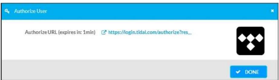
- Click DONE to return to Streaming Services.
To authenticate Deezer streaming:
- Click on the link to log in to the Deezer portal.
NOTE: The link is valid for one minute. After one minute, the link expires, and the Authorize URL is shown as blank. The Authorize User dialogue will need to be closed and reopened.

- Click DONE to return to Streaming Services.
To authenticate Qobuz streaming:
- Click on the link to log in to the Qobuz portal.
NOTE: The link is valid for one minute. After one minute, the link expires, and the Authorize URL is shown as blank. The Authorize User dialogue will need to be closed and reopened.

- Click DONE to return to Streaming Services.
To authenticate SOUNDMACHINE streaming:
NOTE: To determine whether to use commercial accounts, refer to the streaming service license agreement or FAQs on their respective portals. For SOUNDMACHINE, click here.
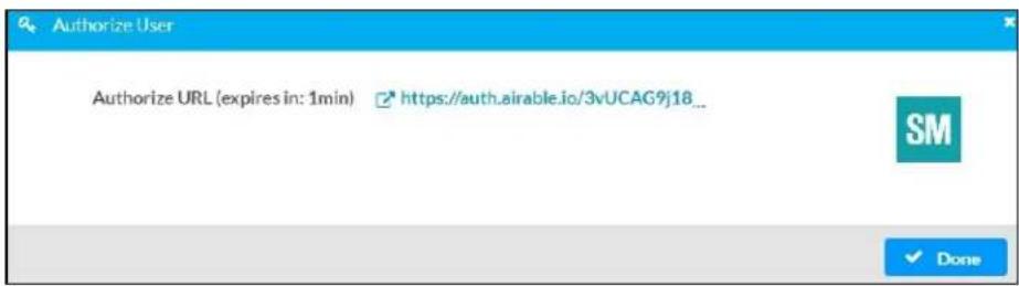
- Click the link to log in to the SOUNDMACHINE portal.
NOTE: The link is valid for one minute. After one minute, the link expires, and the Authorize URL is shown as blank. The Authorize User dialogue will need to be closed and reopened.

- Log in to the SOUNDMACHINE account.
- Click DONE to return to Streaming Services.
To authenticate Pandora streaming:

- Click the icon to copy the activation code.
- Click the link to register the device. The Device Activation page is displayed.
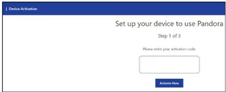
NOTE: The link is valid for one minute. After one minute, the link expires, and the Authorize URL and Enter Code are shown as blank. The Authorize User dialogue will need to be closed and reopened.
- Paste the activation code in the Please enter your activation code field and click Activate Now.
- Log in to the Pandora account.
- Click DONE to return to Streaming Services.
Port Selection
The Port Selection feature allows the device's internal network traffic to be managed and segregated based on traffic type. Internal VLANs are used to segment device management and streaming service traffic to a separate physical device Ethernet port than audio-over-IP streaming traffic. With Port Selection enabled on all DM NAX devices on a network, DM NAX and AES67 network traffic can be physically separated from the control network onto a dedicated audio network.

To configure Port Selection:
- Set the Port Selection toggle to the right position to enable Port Selection. Set the toggle to the left position to disable Port Selection. By default, Port Selection is disabled.
NOTE: Ports 1 and 2 correspond to the Ethernet adapters labeled 1 and 2 on the rear panel of the DM-NAX-4ZSA-50, respectively.
- With Port Selection enabled, select an Ethernet port from the Management drop-down menu to designate which Ethernet port on the rear panel of the device will handle network traffic relating to device configuration, streaming services, and the device's connection to a control system.
NOTES:
- To access streaming services, the Management port must be connected to a network with internet access.
-
The Management port determines your connection to the web interface. Changing the port value can result in losing your connection to the device via the web interface.
-
With Port Selection enabled, select an Ethernet port from the Audio/NAX drop-down menu to designate which Ethernet port on the rear panel of the device will handle audio-over-IP streaming network traffic.
-
Click Save changes to apply the new settings.
NOTE: Making changes to Port Selection settings will require a reboot.
Security
Click the Security tab to configure security for users and groups and to allow different levels of access to the DM-NAX-4ZSA-50 functions. By default, security is disabled.

Select Encrypt and Validate, Encrypt, or OFF in the SSL Mode drop-down menu, to specify whether to use encryption. By default, SSL Mode is set to OFF.
Current User
Click the Current User tab to view read-only information or to change the password for the current user.
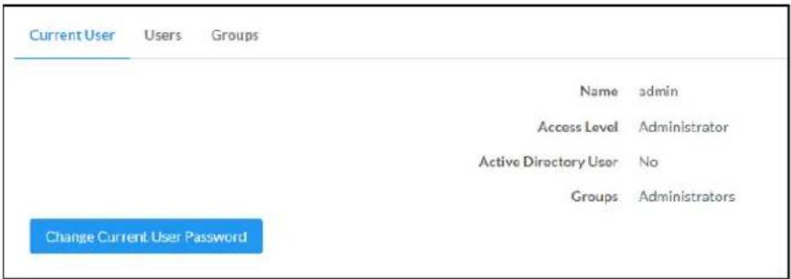
-
Click the Change Current User Password button to provide a new password for the current user.
-
In the Change Password dialog, enter the current password in the Current Password field, the new password in the Password field, and then re-enter the same new password in the Confirm Password field.

- Click OK to save or click Cancel to cancel the changes.
Users
Click the Users tab to view and edit user settings. The Users tab can be used to add or remove local and Active Directory users and preview information about users.

Use the Search Users field to enter search term(s) and display users that match the search criteria.
If users listed in the Users table span across multiple pages, navigate through the list of users by clicking a page number or by using the left or right arrows at the bottom of the Users pane to move forward or backward through the pages.
Each page can be set to display 5, 10, or 20 users by using the drop-down menu to the right of the navigation arrows.
Information about existing users is displayed in table format and the following details are provided for each user.
- Username: Displays the name of the user.
- AD User: Displays whether the user requires authentication using Active Directory.
Click the corresponding button in the Actions column to view detailed user information or to delete the user.
To create a new user, click the Create User button.
Create a New Local User
-
Click the Create User button in the User tab.
-
In the Create User dialog, enter the following:
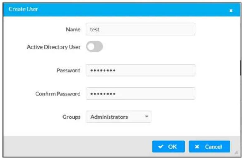
a. Enter a user name in the Name field. A valid user name can consist of alphanumeric characters (letters a-z, A-Z, numbers 0-9) and the underscore "_" character.
b. Enter a password in the Password field; re-enter the same password in the Confirm Password field.
c. Assign the access level by selecting one or more groups from the Groups drop-down list.
NOTE: Make sure that the Active Directory User toggle is disabled.
- Click OK to save or click Cancel to cancel the changes.
Add an Active Directory User
Users cannot be created or removed from the Active Directory server, but access can be granted to an existing user in the Active Directory server.
To grant access to an Active Directory user, you can either add the user to a local group on the DM-NAX-4ZSA-50, or add the Active Directory group(s) that they are a member of to the DM-NAX-4ZSA-50.
To add an Active Directory user.
- Click the Create User button.
- In the Create User dialog, enter the following.

a. Enter a user name in the Name field in the format "Domain\UserName", for example "crestronlabs.com\JohnSmith". Valid user names can contain alphanumeric characters (letters a-z, A-Z, numbers 0-9) and the underscore "_" character.
b. Select one or more groups from the Groups drop-down list.
NOTE: Make sure that the Active Directory User toggle is set to enabled.
- Click OK to save or click Cancel to cancel the changes.
Delete User
Click the trashcan button (☐) in the Actions column to delete the user. Click Yes when prompted to delete the user or No to cancel the deletion.
After a user is removed from a group, they lose any access rights associated with that group. Note that the user account is not deleted by the delete user operation.
View User Details
Click the information button (0) in the Actions column to view information for the selected user. The User Details dialog displays the following information for the selected user.
- Name: Displays the name of the selected user.
• Active Directory User: Displays whether the user is an Active Directory user. - Group: Displays group(s) the selected user is part of.
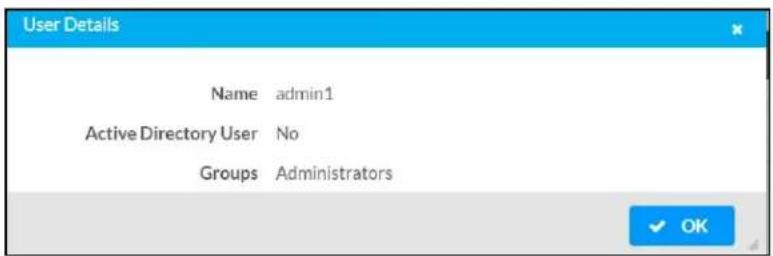
Click OK to close the User Details dialog and to return to the Users tab.
Update User Details
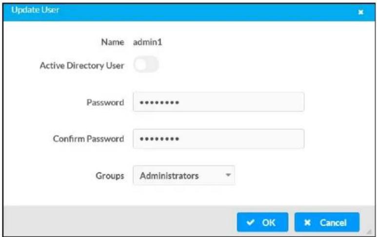
- Click the edit button() in the Actions column to update information for the selected user.
- Enter a password in the Password field; re-enter the same password in the Confirm Password field.
- Select one or more groups to assign the user to from the Groups drop-down list.
- Click OK to save or click Cancel to cancel the changes.
The Update User dialog also displays the following read-only information for the selected user.
• Name: Displays the name of the user.
• Active Directory User: Displays whether the user is an Active Directory user.
Groups
Click the Groups tab to view and edit group settings. The Groups tab can be used to add local and Active Directory groups, remove local and Active Directory groups, and preview information about a group.
Use the Search Groups field to enter search term(s) and display groups that match the search criteria.
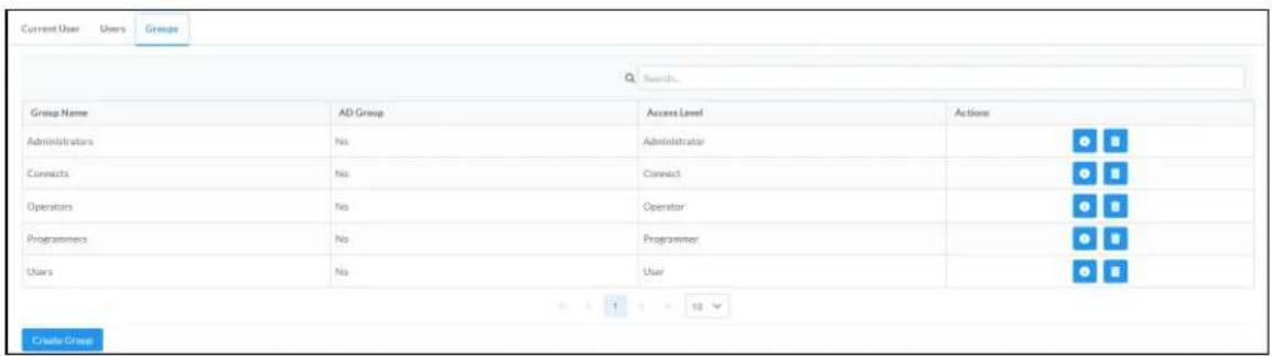
If groups listed in the Groups table span across multiple pages, navigate through the groups by clicking a page number or by using the left or right arrows at the bottom of the Groups pane to move forward or backward through the pages.
Additionally, each page can be set to display 5, 10, or 20 groups by using the drop-down menu to the right of the navigation arrows.
Existing groups are displayed in a table and the following information is provided for each group:
- Group Name: Displays the name of the group.
• AD Group: Displays whether the group requires authentication using Active Directory. - Access Level: Displays the predefined access level assigned to the group (Administrator, Programmer, Operator, User, or Connect).
Click the corresponding button in the Actions column to view detailed group information (☐) or to delete ☐ selected group.
Click on the Create Group button in the Groups tab to create new group.
Create Local Group

- Click the Create Group button.
- In the Create Group dialog, enter the following:
a. Enter the group name in the Name field.
b. Assign the group access level by selecting a predefined access level (Administrator, Connect, Operator, Programmer, User) from the Access Level drop-down list.
NOTE: Make sure that the Active Directory Group toggle is disabled.
- Click OK to save. Click Cancel to cancel the changes.
Add Active Directory Group
A group cannot be created or removed from the Active Directory server, but access can be granted to a existing group in Active Directory.
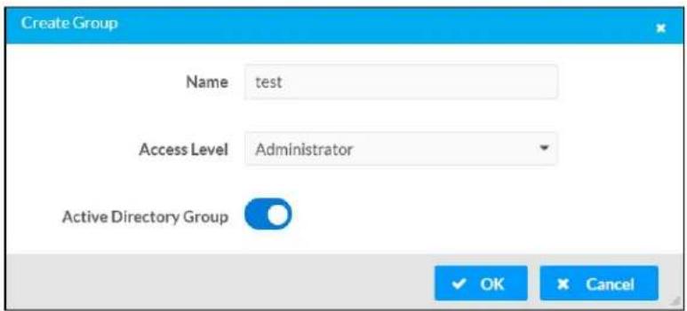
Once the group is added, all members of that group will have access to the DM-NAX-4ZSA-50.
- Click the Create Group button.
- In the Create Group dialog enter the following:
a. Enter the group name in the Name field, for example "Engineering Group". Note that group names are case sensitive; a space is a valid character that can be used in group names.
- Assign the group access level by selecting a predefined access level (Administrator, Connect, Operator, Programmer, User) from the Access Level drop-down list.
NOTE: Make sure that the Active Directory Group toggle is enabled.
- Click OK to save. Click Cancel to cancel the changes.
Delete a Group
Click the trashcan button (☐) in the Actions column to delete a group. Click Yes when prompted to delete the group or No to cancel the deletion.
When a group is deleted, users in the group are not removed from the device or Active Directory server. However, because a user's access level is inherited from a group(s), users within the deleted group will lose access rights associated with the group.
View Group Details
Click the information button (6) in the Actions column to view information for the selected group. The Group Details dialog lists the following information for the selected group.
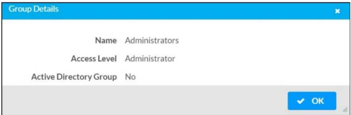
• Name: Displays the name of the group.
- Access Level: Displays the access level of the group and its users.
• Active Directory Group: Displays whether the group is an Active Directory group.
Click OK to close the Group Details dialog and to return to the Groups tab.
802.1x Configuration
The DM-NAX-4ZSA-50 has built-in support for the 802.1X standard (an IEEE network standard designed to enhance the security of wireless and Ethernet LANs. The standard relies on the exchange of messages between the device and the network's host, or authentication server), allowing communication with the authentication server and access to protected corporate networks.
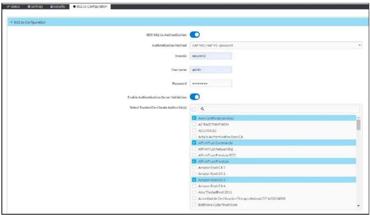
To Configure DM-NAX-4ZSA-50 for 802.1X Authentication
-
Set the IEEE 802.1X Authentication toggle to enabled. This will enable all options on the 802.1X dialog.
-
Select the Authentication method: EAP-TLS Certificate or EAP-MSCHAP V2 Password according to the network administrator's requirement.
-
Do either one of the following:
- Select EAP-TLS Certificate, click Action/Manage Certificates to upload the required machine certificate. The machine certificate is an encrypted file that will be supplied by the network administrator, along with the certificate password.
- Select EAP-MSCHAP V2 Password, enter the username and password supplied by the network administrator into the Username and Password fields. This method does not require the use of a machine certificate, only the user name and password credentials.
- If you enabled the Enable Authentication Server Validation option, this will enable the Select Trusted Certificate Authoritie(s) list box which contains signed Trusted Certificate Authorities (CAs) preloaded into the DM-NAX-4ZSA-50.
Select the check box next to each CA whose certificate can be used for server validation, as specified by the network administrator.
If the network does not use any of the listed certificates, the network administrator must provide a certificate, which must be uploaded manually via the Manage Certificates functionality.
-
If required, type the domain name of the network in the Domain field.
-
When the 802.1X settings are configured as desired, click Save Changes to save the changes to the device and reboot it. Click Revert to cancel any changes.
Access the Web Interface With the Crestron Toolbox Application
To access the web interface by opening a web browser within the Crestron Toolbox™ application, do the following:
-
Open the Crestron Toolbox application.
-
From the Tools menu, select Device Discovery Tool. You can also access the Device Discovery Tool by clicking the Device Discovery Tool button ( ) in the Crestron Toolbox toolbar. The DM-NAX-4ZSA-50 is discovered and listed in the device list on the left side of the screen. The associated host name, IP address, and firmware version are also displayed.
NOTE: If there is security software running on the computer, a security alert might be displayed when the Crestron Toolbox application attempts to connect to the network. Make sure to allow the connection, so that the Device Discovery Tool can be used.
-
In the Device Discovery Tool list, double-click your device.
-
Enter your credentials in the Authentication Required dialog that opens, and then click Log In.
-
Click the Web Configuration button in the Configuration page displayed on the left side of the Device Discovery Tool.
DM-NAX-4ZSP
This section describes how to configure DM-NAX-4ZSP.
Web Interface Configuration
The DM-NAX-4ZSP web interface allows you to view status information and configure network and device settings.
Access the Web Interface
To access the web interface, do either of the following:
- Access the Web Interface with a Web Browser on page 315
- Access the Web Interface With the Crestron Toolbox™ Application on page 374
The web interface is accessed from a web browser. The following table lists operating systems and their corresponding supported web browsers.
Operating System and Supported Web Browsers
| OPERATING SYSTEM SUPPORTED WEB BROWSERS | |
| Windows® operating system | ChromeTM web browser, version 31 and laterFirefox® web browser, version 31 and laterInternet Explorer web browser, version 11 and laterMicrosoft Edge web browser |
| macOS® operating system | Safari® web browser, version 6 and laterChrome web browser, version 31 and laterFirefox web browser, version 31 and later |
Access the Web Interface with a Web Browser
- Enter the IP address of the DM-NAX-4ZSP into a web browser.
NOTE: To obtain the IP address, use the Device Discovery Tool option in Crestron Toolbox™ application or an IP scanner application.
- If you are creating a user account for the first time, do the following; otherwise, skip to step 3.
a. Enter a username in the Username field.
b. Enter a password in the Password field.
c. Re-enter the same password in the Confirm Password field.

d. Click Create User. The Device Administration page appears.

- Enter the username in the Username field.
- Enter the password in the Password field.
- Click Sign In.
Action
The Action drop-down menu is displayed at the top right side of the interface and provides quick access to common device functions:
- Save Changes
- Revert
- Reboot
- Restore
- Update Firmware
- Download Logs
- Manage Certificates
- Manage Audio Profiles
- Download Configuration
- Upload Configuration

Save Changes
Click Save Changes to save any changes made to the configuration settings.
Revert
Click Revert to revert the device back to the last saved configuration settings.
Reboot the DM-NAX-4ZSP
Certain changes to the settings may require the DM-NAX-4ZSP to be rebooted to take effect. To reboot the device, do the following:
- Click Reboot in the Actions drop-down menu. The Confirmation message box appears.

- Click Yes, Reboot Now to reboot the device. The Reboot message box appears.
Wait for the device reboot to complete before attempting to reconnect to the device.
Restore to Factory Default Settings
- Click Restore in the Actions drop-down menu to restore the settings of the DM-NAX-4ZSP to factory defaults.
NOTE: When settings are restored, all settings, including the network settings, will revert to the factory default. If a static IP address is set, restoring the device to factory default settings will revert the IP address to the default DHCP mode.
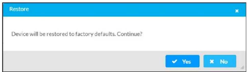
- Click Yes in the Confirmation dialog to restore the DM-NAX-4ZSP to factory settings. Click No to cancel the restore operation.
A dialog is displayed again, indicating that the restore process was successful and that the device rebooted.
You can also restore to factory settings by pressing and holding the SETUP button on the rear panel of the device with power disconnected then connect the power supply and continue to hold SETUP button for 30 seconds.
Update Firmware
-
Click Update Firmware in the Actions drop-down menu.
-
In the Firmware Upgrade dialog, click + Browse.

- Locate and select the desired firmware file, and then click Open. The selected firmware file name is displayed in the Firmware Upgrade dialog.
- Click Load and wait for the progress bar to complete and for the OK button in the message to become clickable.
- Click OK. The device with new firmware can now be accessed.
Download Logs
- Click Download Logs in the Actions drop-down menu to download the device message logs for diagnostic purposes.
The log file is downloaded to the Downloads folder of the PC.
Manage Certificates
Use the Manage Certificates dialog to add, remove, and manage certificates used in 802.1x and other protected networks.

-
Click Manage Certificates in the Actions drop-down menu. The following certificate tabs are displayed:
-
Root: The Root certificate is used by the DM-NAX-4ZSP to validate the network's authentication server. The DM-NAX-4ZSP has a variety of Root certificates, self-signed by trusted CAs (Certificate Authorities) preloaded into the device. Root certificates must be self-signed.
- Intermediate: The Intermediate store holds non self-signed certificates that are used to validate the authentication server. These certificates will be provided by the network administrator if the network does not use self-signed Root certificates.
- Machine: The machine certificate is an encrypted PFX file that is used by the authentication server to validate the identity of the DM-NAX-4ZSP. The machine certificate will be provided by the network administrator, along with the certificate password. For 802.1x, only one machine certificate can reside on the device.
- Web Server: The Web Server certificate is a digital file that contains information about the identity of the web server.
To Add Certificates
- Click the corresponding certificate tab.
- Click the Add Root Certificate button.
- Click the + Browse button.
- Locate and select the file, and then click the Open button.
NOTE: If the certificate is a Machine Certificate, enter the password provided by the network administrator.
- Click OK. This will add the certificate to the list box, displaying the file name and expiration date.
The certificate is now available for selection and can be loaded to the device.
To Delete Certificates
- Click the corresponding certificate tab.
- Click the trashcan button ( ) in the Actions column to delete the certificate.
- Click Yes when prompted to delete the certificate or No to cancel the deletion.
Manage Audio Profiles
Use the Manage Audio Profiles dialog to add, remove, and manage the audio profiles of speakers.
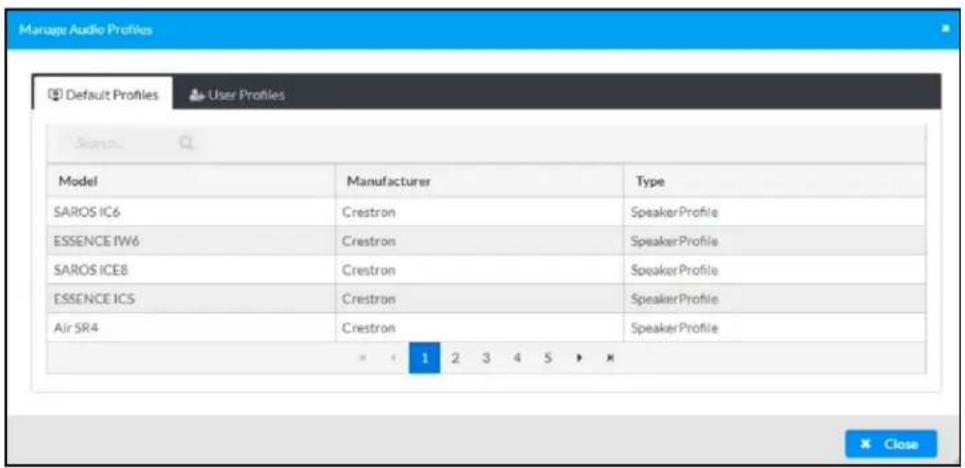
Click Manage Audio Profiles in the Actions drop-down menu. The following audio profiles tabs are displayed, providing information such as Model, Manufacturer, and Type of the speaker profiles:
- Default Profiles: Lists the default library of included speaker profiles.
- User Profiles: Lists the custom, user loaded profiles, and allows them to be loaded and removed.
In the Search field, enter the speaker's profile name to search for the profile. The speaker profile matching the search criteria is displayed.
NOTE: To create a custom speaker profile, see OLH 1001820.
To Add a Speaker Profile
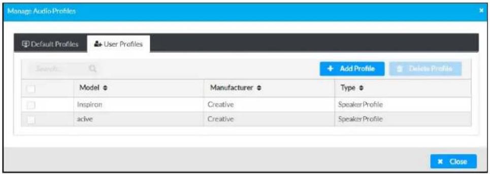
- Click the User Profiles tab.
- Click the + Add Profiles button.
- Click the + Browse button.
- Locate and select the .prof file, and then click the Open button.
- Click the Upload button.
- Click OK. This will add the profile to the list box.
The speaker profile is now available for selection and can be applied to the speaker.
To Delete a Speaker Profile
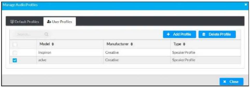
- Click the User Profiles tab.
- Select the checkbox corresponding to the audio profile that needs to be deleted.
- Click Delete Profile button.
The speaker profile is deleted.
Download Configuration
Click Download Configuration to download a TGZ file containing the settings data for the DM NAX device.
NOTE: User accounts for accessing the device, streaming service accounts, multicast addresses, and stream names are not saved in this configuration file.
Upload Configuration
- Click Upload Configuration to upload a TGZ file that will overwrite the current settings of the DM NAX device with a saved configuration.
CAUTION: Be sure to load a TGZ file for the same DM NAX device type while using the Load Configuration feature. For example, if loading a TGZ file to a DM-NAX-16AIN, be sure that the TGZ file originated from a DM-NAX-16AIN.
- Click Browse to navigate to the desired TGZ file in your file browser. Double-click the file or highlight it and click Open.

- Click Upload to begin the file upload process. A progress bar will indicate the status of the configuration file upload.

- Once the upload is complete, the device will require a reboot. Click Yes, Reboot Now to begin the reboot, or click No to return to the web UI.
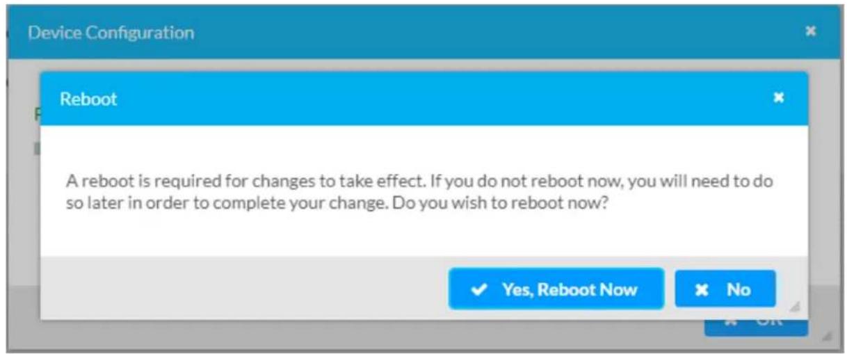
NOTE: Any changes made after the configuration file upload, but before a device reboot, may be overwritten when the device is rebooted.
Status
The Status tab is the first page displayed when opening the interface of the DM-NAX-4ZSP. It displays general information about the DM-NAX-4ZSP (such as Model Name, Firmware Version, and Serial Number), current network settings (such as Host Name and IP Address, etc.), and input and output ports' current status.
The Status tab can be accessed at any time by clicking the Status tab of the DM-NAX-4ZSP interface.
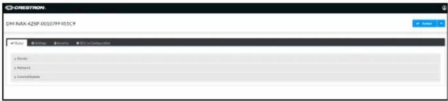
Information displayed on the Status tab is organized into different sections.
Device
The Device section displays the Model, Firmware Version, and Serial Number of the DM-NAX-4ZSP.
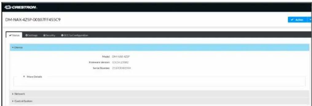
Click + More Details to review additional information about the DM-NAX-4ZSP.
| More Details | |
| DM-NAX-4ZSP | 0.5154.23582 |
| Build | Feb 11.2022 (449289) |
| Updater | 0.5154.23582 |
| Bootloader | 0.04.00 |
| CCUI Version | 1.602.877345 |
| XIOSDK | 3.8.0 |
| IoTSDK | 1.6.0 |
| Build time | 00:18:24 |
| Product ID | 0x7AFF |
| Revision ID | 0x0400 |
| ctrl-audio-dsp-0 | FW v38 (Driver v3.9) |
| ctrl-audio-dsp-1 | FW v38 (Driver v3.9) |
| ctrl-audio-fpga | FW v0.25 (Driver v1.2) |
| ctrl-sigma-dsp-0 | FW v1.00 (Driver v1.1) |
| ctrl-sigma-dsp-1 | FW v1.00 (Driver v1.1) |
| ctrl-hps-fpga | FW v1.20.2433093 (Driver v2.1) |
| PUF | Unknown |
| Forced Auth Mode | True |
Network
The Network section displays network-related information about the DM-NAX-4ZSP, including the Hostname, Domain Name, and DNS Servers.

NOTE: By default, the host name of the DM-NAX-4ZSP consists of the model name followed by the MAC address of the device. For example, DM-NAX-4ZSP-00107FF455C9.
Click + Adapter 1 to display an expanded section that shows additional information. If + Adapter 1 is selected, click - Less details to collapse the section.
NOTE: The + Adapter 2 option appears when the dual Ethernet ports on the DM-NAX-4ZSP are set to isolate traffic using the Port Selection feature.
Control System
The Control System section displays connection information, consisting of the following:

- Encrypt Connection: ON or OFF
• IP ID: Reports the currently used IP ID of the DM-NAX-4ZSP - IP Address/Hostname: The IP address of the control system
• Room ID: Displays the room ID
• Status: OFFLINE or ONLINE
Settings
The Settings tab enables you to configure the DM-NAX-4ZSP settings. The Settings page can be accessed at any time by clicking the Settings tab of the DM-NAX-4ZSP interface.

Settings available on the Settings tab are organized into different sections.
System Setup
The System Setup section contains settings for Date/Time, Auto Update, Network, and Control System.
Date/Time
Use the Date/Time section to configure the date and time settings of the DM-NAX-4ZSP.
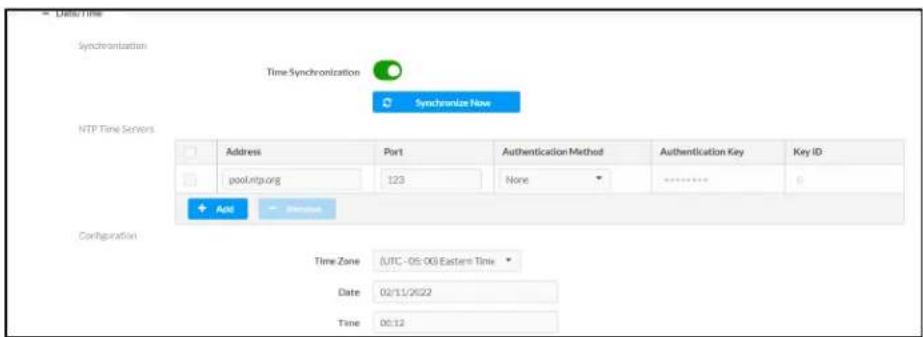
Time Synchronization
- Set the Time Synchronization toggle to the right position to enable or left position to disable time synchronization. By default, time synchronization is enabled.
- In the NTP Time Servers table, enter the URL of a NTP (Network Time Protocol) or SNTP (Simple Network Time Protocol) server. Up to three time servers can be added on a device.
- Click Synchronize Now to perform time synchronization between the device's internal clock and the time server.
Time Configuration
- Click on the Time Zone drop-down menu to select the applicable time zone.
- In the Date field, enter the current date.
- In the Time (24hr Format) field, enter the current time in 24-hour format.
Click the Save Changes button to save the settings.
Click Revert from the Actions drop-down menu to revert to the previous settings without saving.
Auto Update
The DM-NAX-4ZSP can automatically check for and install firmware updates at scheduled intervals via the Auto Update feature.
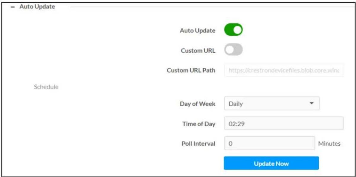
- Set the Auto Update toggle to the right position to enable Auto Update.
- Define the URL to download the updates by doing either of the following:
a. Use the default URL to download the updates from the Crestron server.
b. Use a custom URL. Set the Custom URL toggle to the right position to enable a custom URL. In the Custom URL Path text box, enter the path to a custom manifest file in the F or SFTP URL format. Use the Crestron Auto Update Tool to generate a custom manifest file, then store the file on an FTP (File Transfer Protocol) or SFTP (Secure File Transfer Protocol) server.
- Set a schedule for the automatic firmware update by doing either of the following:
a. Select the desired Day of Week and Time of Day (24-hour format) values.
b. Set the Poll Interval by entering a value from 60 to 65535 minutes. A value of 0 disables the Poll Interval.
- Click Save Changes.
Clicking Update Now causes the device to check for a firmware update immediately. If a schedule was set in step 4 above, that schedule still remains in effect.
Network
The Network section contains network-related settings for the DM-NAX-4ZSP, including the Hostname, Domain, Primary Static DNS, and Secondary Static DNS.
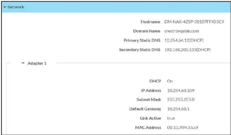
NOTE: By default, the hostname of the DM-NAX-4ZSP consists of the model name followed by the MAC address of the device. For example, DM-NAX-4ZSP-00107FB58088.
Adapter 1
The Adapter 1 subheading contains settings for DHCP, IP Address, Subnet Mask, and Default Gateway of Ethernet adapter 1 on the rear panel of the device.
NOTES:
- An + Adapter 2 option only appears when the dual Ethernet ports on the DM-NAX-4ZSP are set to isolate traffic using the Port Selection feature. The settings for Adapter 2 are identical to those available for Adapter 1.
- DM NAX devices' internal processes use IP addresses in the 10x10.10nge. This IP range should be avoided when addressing DM NAX devices to prevent conflicts.
Set the DHCP toggle to enabled (right) or disabled (left) to specify whether the IP address of the DM-NAX-4ZSP is to be assigned by a DHCP (Dynamic Host Configuration Protocol) server.
- Enabled: When DHCP is enabled (default setting), the IP address of the DM-NAX-4ZSP is automatically assigned by a DHCP server on the local area network (LAN).
-
Disabled: When DHCP is disabled, manually enter information in the following fields:
-
Primary Static DNS: Enter a primary DNS IP address.
Secondary Static DNS: Enter a secondary DNS IP address. - IP Address: Enter a unique IP address for the DM-NAX-4ZSP.
- Subnet Mask: Enter the subnet mask that is set on the network.
Default Gateway: Enter the IP address that is to be used as the network's gateway.
To save any new network entries, click Save Changes.
Control System

- Click the Encrypt Connection button to navigate to the Security tab to configure encryption settings.
- Enter the username in the Control System Username field.
- Enter the password in the Control System Password field.
- Enter the Room ID in the Room ID field.
- Enter the IP ID of the DM-NAX-4ZSP in the IP ID field.
- Enter the IP address or hostname of the control system in the IP Address/Hostname field.
- Click the Save Changes button to save the new entries. The Control System Save message box appears, indicating that the control system settings were saved successfully. Click the Revert button to revert to the previous settings without saving.
Commissioning
The Commissioning section provides a quick way to automatically assign multicast addresses to all of the device's internal audio-over-IP stream transmitters.
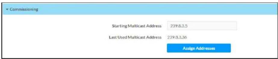
Click Assign Addresses to give each DM NAX transmitter in the DM-NAX-4ZSP a unique multicast address beginning with the specified Starting Multicast Address. The valid range for Starting Multicast Address is 239.8.0.0 to 239.255.255.239.
NOTE: This will begin transmitting multicast traffic on your network, refer to the DM NAX Audio-over-IP System Design Guide document for details.
Chimes
The Chimes section allows the built-in chime files to be assigned to any of the output zones on the device.

For each chime file, click the cells corresponding to the desired Zones for playback of that specific chime sound. You can assign multiple chimes to the same zone. To view all available chimes, use the or arrows at the left of the matrix to change pages.
To configure the chime volume of a zone:
- Click the icon corresponding to the zone. A Configure window appears.

-
To set the volume, do one of the following:
-
Move the Volume slider to the right to increase or to the left to decrease the chime volume
- Click the % arrows to increase or decrease the chime volume. Values range from 0 to 100%, adjustable in increments of 1%.
- Manually enter a value in the Volume field.
NOTE: The chime volume is independent of the zone volume control.
-
Set the Do Not Disturb toggle to the right to mute all chimes for the zone. Set the Do Not Disturb toggle to the left to unmute the chimes.
-
Click OK to apply the new settings.
Zones
The Zones section contains the Volume and Mute settings for all zone outputs of the device, as well as a Configure option for more advanced settings within each zone.
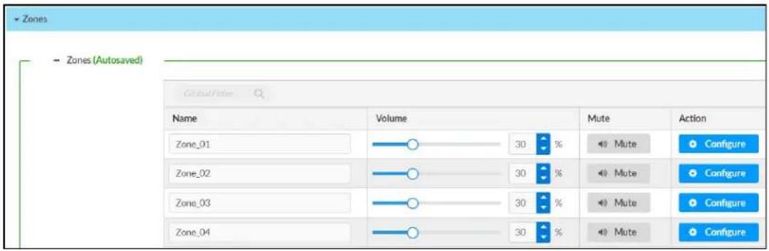
Give each zone a friendly name using the Name column of the Zones table. If the device is paired with a control system, these names may be overwritten by the control system's program.
To configure the zone volume, do one of the following:
- Move the Volume slider to the right to increase or to the left to decrease the zone volume.
- Click the % arrows to increase or decrease the zone volume. Values range from 0 to 100%, adjustable in increments of 1%.
- Manually enter a value in the Volume field.
To mute all audio output from a zone, click its respective Mute button. To unmute the zone, click the Muted button.
Zone Settings
To configure zone settings, click the Configure button (Configure). The Edit Zone window appears.
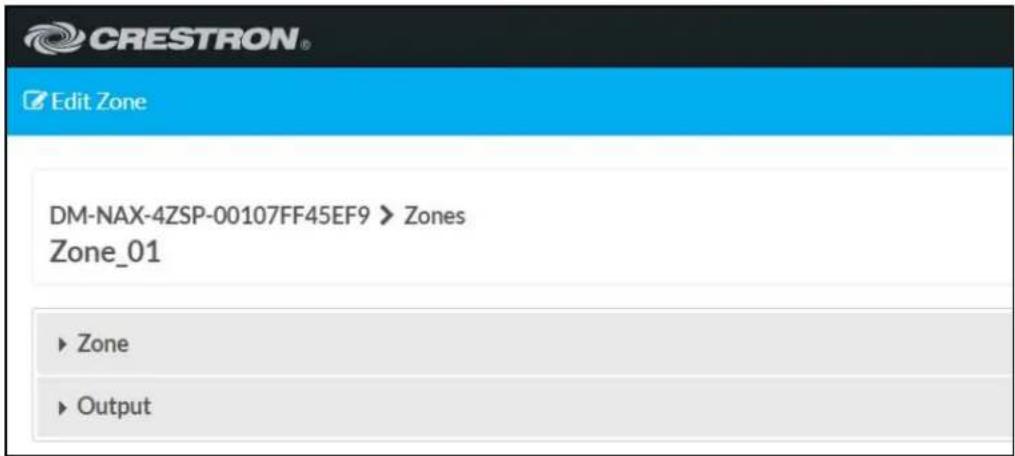
Zone
Click Zone to configure Tone (Autosaved), Balance (Autosaved), and Delay (Autosaved).

Tone

The Tone section provides adjustments for the Tone Profile, Bass, Treble, Loudness, and Night Mode settings of the zone output.
NOTE: The Tone Profile, Bass, Treble, and Loudness settings in the Tone section are all applied separately from the Equalizer Settings for the zone. This means that any adjustments made in the Tone section will stack with those made in the Equalizer Settings section.
-
To select a tone profile preset for the zone, select an option from the Tone Profile drop-down menu. The available options are Off, Classical, Jazz, Pop, Rock, and Spoken Word. By default, Off is selected.
-
Bass: To adjust the bass, do one of the following:
-
Move the Bass slider to the right to increase or to the left to decrease the bass.
- Click the db arrows to increase or decrease the db. Values range from -12 db to 12 db, adjustable in increments of 1 db.
-
Manually enter a value in the Bass field.
-
Treble: To adjust the treble, do one of the following:
-
Move the Treble slider to the right to increase or to the left to decrease the treble.
- Click the db arrows to increase or decrease the db. Values range from -12 db to 12 db, adjustable in increments of 1 db.
-
Manually enter a value in the Treble field.
-
To enable the loudness setting on the zone output, slide the Loudness switch to the right. To disable loudness, slide the Loudness switch to the left.
-
The Night Mode feature applies subtle processing to restrict the dynamic range of the zone audio, to allow for lower listening levels at night or in rooms where higher listening levels would be disruptive. To select a dynamics processing level, select an option from the Night Mode drop-down menu. The available options are Off, Low, Medium, and High. By default, Off is selected.
Balance

To adjust the left/right balance of the stereo output signal, do one of the following:
- Move the Balance slider to the right to shift the stereo balance to the right channel or to the left to shift the balance to the left.
- Click the arrows to adjust the balance left or right. The up arrow shifts the balance to the right while the down arrow shifts the balance to the left.
- Manually enter a value in the Balance field. Values range from -50 to 50, adjustable in increments of 1. Positive values shift the balance to the right while negative values shift the balance to the left.
Delay

To set the delay, do one of the following:
- Move the Delay Time(ms) slider to the right to increase or to the left to decrease the delay time.
- Click the ms arrows to increase or decrease the delay. Values range from 0 ms to 250 ms, adjustable in increments of 1 ms.
- Manually enter a value in the Delay Time(ms) field.
Output
Click Output to access the settings for Minimum/Maximum Volume, Stereo/Mono, Signal, Bussing Volume Offset, Configure Speaker Profile, Speaker Configuration, Casting, Line Out, Signal Generator, Advanced Signal Generator, and Equalizer Settings.

Minimum/Maximum Volume

bar
| Category | Value (%) | |---|---| | Minimum | 14 | | Maximum | 86 | | Default | 27 |-
To set the minimum volume of the zone, do one of the following:
-
Move the Minimum slider to the right to increase or to the left to decrease the minimum volume.
- Click the % arrows to increase or decrease the minimum volume. Values range from 0 to 50%, adjustable in increments of 1%.
-
Manually enter a value in the Minimum field.
-
To set the maximum volume of the zone, do one of the following:
-
Move the Maximum slider to the right to increase or to the left to decrease the maximum volume.
- Click the % arrows to increase or decrease the maximum volume. Values range from 70 to 100%, adjustable in increments of 1%.
- Manually enter a value in the Maximum field.
NOTE: When a Minimum and Maximum volume are set, the 1-100% range represented by the Zone and Default volume controls are scaled to the range set. For example, if a Minimum of 10% and a Maximum of 80% are set for a zone, the 1-100% range of the Zone volume control is scaled to the 10%-80% range set as the Minimum and Maximum.
-
To set the default volume of the zone, do one of the following:
-
Move the Default slider to the right to increase or to the left to decrease the default volume.
- Click the % arrows to increase or decrease the default volume. Values range from 0 to 50% adjustable in increments of 1%.
- Manually enter a value in the Default field.
NOTE: The Default volume is applied as the Zone volume any time the zone receives a source route and no source was previously routed to that zone.
Stereo/Mono

- Select either Stereo or Mono from the Stereo/Mono field.
NOTE: The Zone Configuration field is reserved for future use on the DM-NAX-4ZSP. Currently, the only available value is Standard.
Signal

The Signal section is a read-only field that displays the Signal and Clipping status of the zone output.
- If an output signal is present but not clipping, Signal will display Present in green and Clipping will display None in green.
- If an output signal is present and clipping, Signal will display Present in green and Clipping will display Present in red.
- If no output signal is detected, Signal will display Not Present in red and Clipping will display None in green.
Bussing Volume Offset

Bussing Volume Offset is an additional level compensation applied to the zone relative to any other zones it is grouped with via the Bussing feature.
To set the bussing volume offset, do one of the following:
- Move the Bussing Volume Offset slider to the right to increase or to the left to decrease the offset.
- Click the db arrows to increase or decrease the offset. Values range from -12 dB to 12 dB, adjustable in increments of 1 dB.
- Manually enter a value in the Bussing Volume Offset field.
Configure Speaker Profile
The DM-NAX-4ZSP has a library of built-in speaker profiles that contain equalizer and maximum output level settings specific to Crestron and third-party speaker models. Custom speaker profiles can also be generated and loaded to the DM-NAX-4ZSP. The Configure Speaker Profile field is used to apply these speaker profiles to a given zone of the DM NAX device.
NOTE: Applying a speaker profile on a zone will overwrite the existing Speaker Configuration and Equalizer settings for that zone.
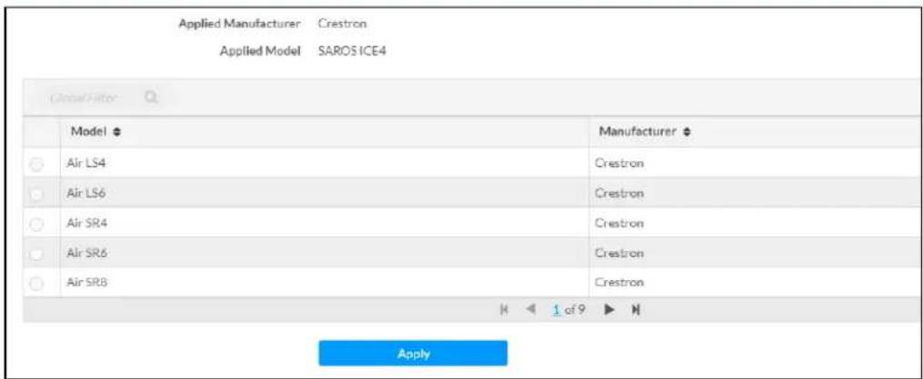
In the Global Filter field, enter the speaker's model name to search for its associated profile. Any speaker profiles matching the search criteria are displayed.
To apply a speaker profile:
-
Select the radio button corresponding to the speaker profile.
-
Click Apply.
The equalizer, impedance, and speaker protection settings of the zone are updated as per the applied speaker profile.
After applying a speaker profile, the Speaker Configuration and Equalizer settings for the zone can still be edited. The Configure Speaker Profile section will display a notification if these settings were altered after the speaker profile was applied.

Speaker Configuration
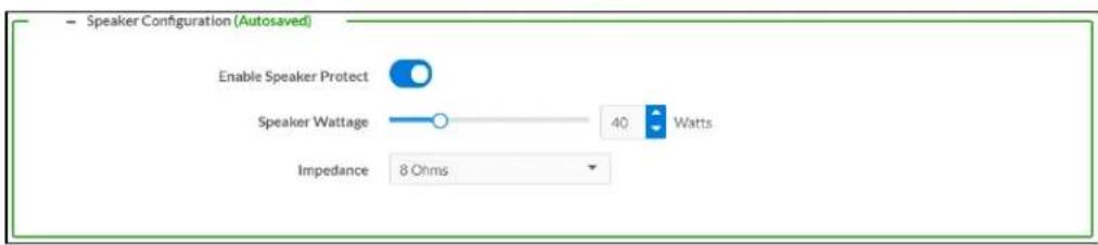
-
Set the Enable Speaker Protect toggle to the right position to enable speaker protection for the zone output. Set the toggle to the left position to disable speaker protection. By default, Enable Speaker Protect is set to the left position.
-
To set the maximum output wattage, do one of the following:
-
Move the Speaker Wattage slider to the right to increase or to the left to decrease the maximum peak amplifier wattage that can be output to the speaker.
- Click the Watts arrows to increase or decrease the maximum peak amplifier wattage that can be output to the speaker. Values range from 5 W to 150 W, adjustable in increments of 1 W.
-
Manually enter a value in the Speaker Wattage field.
-
Select the impedance of the speaker on a selected zone from the Impedance drop-down menu.
Values are 4 Ohms, 8 Ohms, and Bridged.
Casting

The Casting section is used to enable or disable the ability of third-party devices to cast audio to the DM NAX output zone, as well as set a maximum casting volume and friendly name for the zone.
To configure Casting:
- Maximum Casting Volume is an alternate value for the Maximum volume set in the
Minimum/Maximum Volume on page 338 settings, applied to the zone only when a casting service is routed to it. To set the maximum casting volume, do one of the following:
- Move the Maximum Casting Volume slider right to increase or left to decrease the maximum volume.
- Click the arrows to increase or decrease the maximum casting volume. Values range from 70% to 100%, adjustable in increments of 1%.
- Manually enter a value in the Maximum Casting Volume field.
NOTE: If the Maximum Casting Volume value is higher than the regular Maximum volume value, the Maximum value will be applied instead.
- A custom casting name (for example, "Living Room") must be entered so that a name for the zone will be displayed in the list of available casting destinations when initiating a stream. Enter this friendly name in the Casting Name field.
NOTE: Ensure that the Casting Name field is populated as any field with an asterisk (*) is mandatory.
Once AirPlay ^® and/or Spotify Connect ^™ are enabled, this name will be displayed as an available destination on the casting device.
To configure Apple AirPlay ^® casting:
- Set the AirPlay toggle to the right to enable AirPlay casting to the zone's associated media player. Set the AirPlay toggle to the left to disable AirPlay casting to the associated media player.
To configure Spotify Connect™ casting:
- Set the Spotify toggle to the right to enable Spotify Connect casting to the zone's associated media player. Set the Spotify toggle to the left to disable Spotify Connect casting to the associated media player.
To stream media from an iOS device or Spotify app to a zone in your distributed audio system, refer to the DM-NAX-4ZSP Quick Start.
To stream media from a Roon ^® streaming device to a zone in your distributed audio system:
- Enable Apple AirPlay casting for each DM NAX zone.
- Launch the Roon desktop app.
- Open the Roon app menu and navigate to the Settings submenu, then select Audio. A table of discovered network devices that the Roon device can stream to will be displayed. Any devices that previously have been enabled for Roon casting are listed under the Connected to Core section, and the rest of the discovered devices are listed under Other network devices.
- Find each of the DM NAX zones in the Other network devices list, then click the Enable button for each zone to connect it to the Roon Core ^® for casting.
- Return to the Roon app home page and click on the speaker icon at the bottom right. Select a DM NAX zone from the list of available casting destinations. With a zone selected, start a media stream, and the Roon device will cast the streaming audio to the zone.
Line Out

Line Out Volume controls the volume level of the corresponding line-level output on the DM NAX device. The Line Out Volume is only applied when Line Out EQ Bypass is enabled.
-
To set the line out volume, do one of the following:
-
Move the Line Out Volume slider to the right to increase or to the left to decrease the line out volume.
- Click the arrows to increase or decrease the line out volume. Values range from 0 to 100, adjustable in increments of 1. This range in dB is -80 dB to 20 dB.
-
Manually enter a value in the Line Out Volume field.
-
Set the Line Out EQ Bypass toggle to the right position to have the line-level output signal bypass the zone's equalizer settings. Set the toggle to the left position to have the line-level output signal pass through the zone's equalizer. By default, Line Out EQ Bypass is disabled.
NOTE: When the Line Out EQ Bypass setting is disabled, the line-level output's level will follow the speaker output's Zone volume control. This allows for a variable line-level output in applications where the line-level output is connected to an uncontrolled device such as powered speakers. If the Line Out EQ Bypass setting is enabled, the Line Out Volume slider can be used to set a fixed level for the line-level output. This level will not be affected by the speaker output Zone volume controls, which is better suited to applications where the line output is connected to a controlled amplifier with its own level adjustment.
Signal Generator

The DM-NAX-4ZSP has a built-in signal generator that allows an integrator to send an audio signal to any number of selected zones to test output functionality.
- To route the signal generator to the zone output, click the Signal Generator button so that it displays Active and is highlighted in blue. To unroute the signal generator on the zone output, click the Signal Generator button so that it displays Inactive and is highlighted in grey. By default, the signal generator is not routed to the zone output.
NOTES:
- There is only one signal generator built-in to the DM NAX device. Each zone has its own button to enable or disable the signal generator from passing signal to that output. Setting the signal generator to Inactive on a given zone output only breaks the route for that output and does not stop it from playing back in other zones.
-
The Signal Generator Volume control is a local control that does not affect the signal generator's volume on other zone outputs. Only the settings under Advanced Signal Generator are applied universally to all zones of the DM NAX device.
-
To adjust the signal generator's volume, do one of the following:
-
Move the Signal Generator Volume slider right to increase or left to decrease the volume.
- Click the arrows to increase or decrease the signal generator volume. Values range from 0 to 100, adjustable in increments of 1.
- Manually enter a value in the Signal Generator Volume field.
Advanced Signal Generator

The advanced signal generator settings control the built-in signal generator directly, and are applied universally to all output zones of the DM NAX device. The signal type for the generator can be set, and the left and right channels of the test signal can be individually enabled or disabled.
- Set the Left Channel toggle to the right position to enable the left channel of the signal. Set the toggle to the left position to disable the left channel. By default, Left Channel is enabled.
-
Set the Right Channel toggle to the right position to enable the right channel of the signal. Set the toggle to the left position to disable the right channel. By default, Right Channel is enabled.
-
Select an audio test signal type from the Signal Type drop-down menu. The available signal types are:
-
Tone: Generates a 1 kHz sine wave tone.
- Pink Noise: Generates pink noise.
- White Noise: Generates white noise.
Equalizer Settings
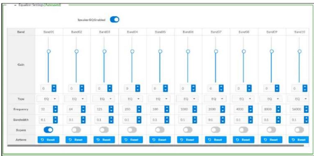
bar
| Band | Band01 | Band02 | Band03 | Band04 | Band05 | Band06 | Band07 | Band08 | Band09 | Band10 | |------|--------|--------|--------|--------|--------|--------|--------|--------|--------|--------| | Gain | 0 | 0 | 0 | 0 | 0 | 0 | 0 | 0 | 0 | 0 | | Type | EQ | EQ | EQ | EQ | EQ | EQ | EQ | EQ | EQ | EQ | | Frequency | 32 | 64 | 125 | 250 | 500 | 1000 | 2000 | 4000 | 8000 | 16000 | | Bandwidth | 0.1 | 0.1 | 0.1 | 0.1 | 0.1 | 0.1 | 0.1 | 0.1 | 0.1 | 0.1 | | Bypass | Reset | Reset | Reset | Reset | Reset | Reset | Reset | Reset | Reset | Reset |Each zone output of the DM-NAX-4ZSP has a dedicated ten-band equalizer that can be fully customized to tune the zone output signal to the needs of an install. Each band can have a discrete ga filter type, center frequency, and bandwidth set, and can also be bypassed. The equalizer itself can also be bypassed using the Speaker EQ Enabled toggle.
- Set the Speaker EQ Enabled toggle to the right position to enable the equalizer. Set the toggle to the left position to bypass the equalizer.
NOTE: When Speaker EQ Enabled is disabled, all equalizer bands are bypassed. This is a quick way to perform A/B testing of the entire EQ curve.
- With the Speaker EQ Enabled toggle in the right position, do the following to configure a given equalizer band:
a. To set a band's gain, do one of the following:
- Move the Gain slider up to increase or down to decrease the gain.
- Click the arrows to increase or decrease the gain. Values range from -40 dB to 20 dB, adjustable in increments of 0.1 dB.
- Manually enter a value in the Gain field.
b. Select a filter type from the Type drop-down menu. By default, all bands are set to the EQ filter type. Some filter types will disable other settings in their respective band while enabled. For example, selecting the LowPass filter type for a band will disable that band's Gain and Bandwidth settings, since the LowPass filter applies a fixed roll-off slope at a set frequency. The available filter types are:
- EQ: a fully parametric filter that can boost or cut a range of frequencies.
- Notch: a parametric filter designed to more precisely cut a frequency or range of frequencies. A notch filter can achieve a narrower bandwidth than the standard EQ parametric filter type.
- TrebleShelf: a filter that boosts or cuts all frequencies above a set frequency by a set gain.
- BassShelf: a filter that boosts or cuts all frequencies below a set frequency by a set gain.
- LowPass: a filter that fully cuts all frequencies above a set frequency using a fixed roll-off slope of -12 dB per octave.
- HighPass: a filter that fully cuts all frequencies below a set frequency using a fixed roll-off slope of -12 dB per octave.
c. Set a center frequency for the equalizer band to tune a specific portion of the audible frequency spectrum. To set the center frequency, do one of the following:
- Click the arrows to increase or decrease the frequency. Values range from 20 Hz to 20 kHz, adjustable in increments of 1 Hz. Each band has a default center frequency that will be applied if the Reset button at the bottom of the band is clicked.
- Manually enter a value in the Frequency field.
d. Set a bandwidth to determine how wide of a frequency range is effected by the equalizer band. To set the bandwidth, do one of the following:
- Click the arrows to increase or decrease the bandwidth. Values range from 0.1 octaves to 4.0 octaves, adjustable in increments of 0.1 octave.
- Manually enter a value in the Bandwidth field.
e. The individual Bypass controls allow you to bypass a single band of equalization at a time for more granular A/B testing of a single filter. Set a band's Bypass toggle to the right position to bypass that band. Set the toggle to the left position to disable the bypass. By default, Bypass is disabled.
f. Each equalizer band has a Reset button that will reapply the default settings for that band.
Click Done to return to the Settings tab of the web user interface.
Bussing
The bussing feature on DM NAX devices allows an integrator to assign any number of selected zones to a fixed group of zones (bus). Zones in a bus track the other zones' volume and routing. For example, when the source or volume for one zone in the bus is adjusted, all other zones in that bus receive the same adjustment. You can create up to two buses on the DM-NAX-4ZSP.

Configure Bussing
-
If needed, enter a friendly name for each bus in its Name field.
-
Select any number of zones from the Included Zones drop-down menu.
NOTE: Each zone can be a member of only one bus. Any zones that are already a member of another bus will not be shown in the Included Zones drop-down.
Inputs
The Inputs menu is used to configure Name, Compensation, and Mute attributes of the available analog, digital, and media streaming inputs on the DM-NAX-4ZSP.
A total of 12 inputs are available on the DM-NAX-4ZSP, including the 8 physical input connectors on the device's rear panel and the 4 internal media players used for media streaming services.

flowchart
graph TD
    A["Inputs (Pulsured)"] --> B["Gain (dB)"]
    B --> C["TSOLINK1"]
    B --> D["TSOLINK2"]
    B --> E["S-POF1"]
    B --> F["S-POF2"]
    B --> G["RCA1"]
    B --> H["RCA2"]
    B --> I["RCA3"]
    B --> J["RCA4"]
    C --> K["Signal Present"]
    D --> L["Clipping Detected"]
    E --> M["Mute"]
    F --> N["Signal Present"]
    G --> O["Clipping Detected"]
    H --> P["Signal Present"]
    I --> Q["Clipping Detected"]
    J --> R["Signal Present"]
Configure Inputs
-
If needed, enter a friendly name for each input in its Name field.
-
To set a level compensation adjustment for a given input, do one of the following:
- Move the Compensation slider up to increase or down to decrease the compensation. Compensation increases or decreases the level of the incoming audio signal on any of the physical inputs on the device's rear panel. Compensation is not available for any of the internal media players.
- Click the db arrows to increase or decrease the compensation. Values range from -10 dB to 10 dB, adjustable in increments of 1 dB.
- Manually enter a value in the Compensation field.
- To mute the signal from the corresponding input, click the Mute button. To disable the mute, click the Muted button. By default, Mute is disabled.
Monitor the device's input signals using the text indicators in the Signal Present and Clipping Detected columns:
• Signal Presence indicates whether or not a signal is detected in that zone.
- Clipping Detected indicates if the signal is Clipping or Nominal (non-clipping).
Use the Global Filter text field to filter specific inputs by name. Not all of the available inputs are shown on the first page in this section when no Global Filter is applied. Use ▶ at the bottom of the table to view the next page of inputs.
DM NAX Streams
Each local input of the DM-NAX-4ZSP can be made available as a DM NAX audio-over-IP stream. This includes the eight physical inputs on the rear panel of the device and the four internal media players.
The DM-NAX-4ZSP also supports parallel DM NAX streams for each zone output, enabling an additional transmit stream per output to mirror all routes and DSP settings of its respective zone. These parallel streams enable control of the audio signal to third-party uncontrolled AES67 devices receiving audio from the DM-NAX-4ZSP.
NOTES:
- Under the Transmitters section (see Configure Transmitters), the last four listed transmitters are dedicated to parallel zone outputs.
• To configure the DSP settings, see Zone Settings.
Click NAX Streams to expand the tab and display the following information.
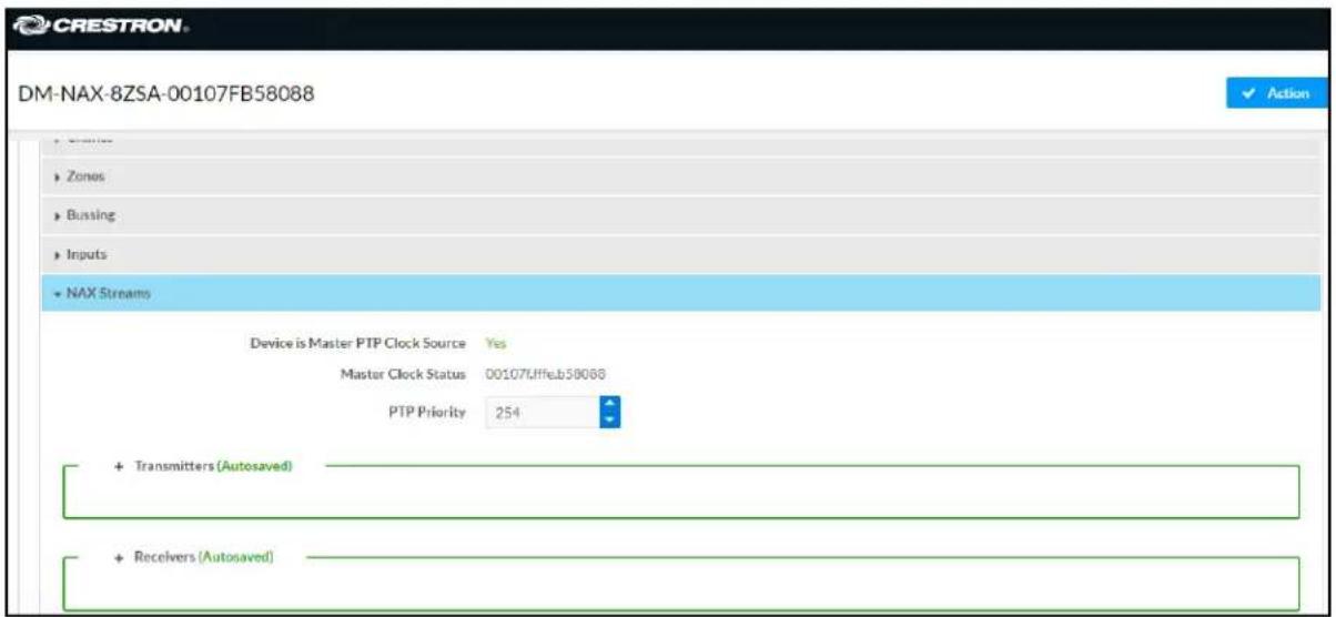
- Device is Master PTP Clock Source indicates whether the device is the master for PTP on the network. Yes will be displayed in green when the local DM-NAX-4ZSP is the PTP clock master and No will be displayed in red when another PTP clock on the network is operating as the master clock.
- Master Clock Status displays the Master Clock ID of the device on the network that acts as the Master Clock.
- PTP Priority: This sets the priority of the local DM NAX device's PTP clock relative to other clocks on the network. The default setting is 254 (one increment higher than the lowest possible value) so that the DM-NAX-4ZSP will only operate as clock master if no other PTP master is present on the network. Valid values range from 1 to 255.
Configure Transmitters
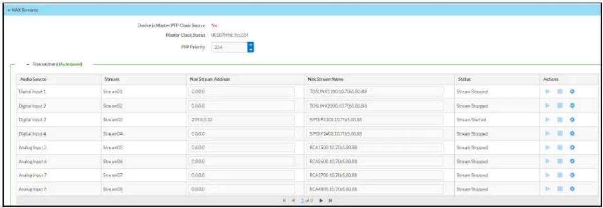
NOTE: To configure transmitters not shown on the current page of the table, click the icon to display the next page of eight transmitters.
To configure a DM NAX transmit stream, do the following.
- Enter a valid multicast address in the NAX Stream Address field.
- Enter a name in the NAX Stream Name field by which the stream can be identified. This stream name is associated with the DM NAX stream's multicast address by other DM NAX or AES67 devices, like a device hostname that resolves to a given IP address.
- Status indicates whether a stream is transmitting or not. When the stream has started or stopped, the Status column will update accordingly.
- Click the configure button (💡) in the Actions column. The Configure dialog appears:
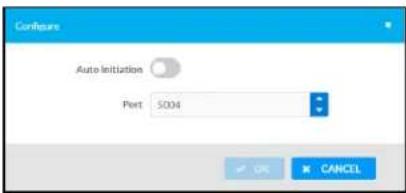
-
Set the Auto Initiation toggle to the right position to enable auto initiation. Set the toggle to the left position to disable auto initiation.
-
If Auto Initiation is enabled for a given stream, the stream will begin transmitting automatically and will be available as a multicast stream on your network at the specified multicast address.
-
If Auto Initiation is disabled for the input, the stream will not begin transmitting until it is manually initiated.
-
To set the port number, do one of the following:
-
Click the arrows to increase or decrease the port number by increments of 1.
-
Manually enter a port number in the Port field. The default port number for DM NAX streams is 5004.
-
Click OK to save or click Cancel to cancel the changes.
Configure Receivers
| - Recivers (Autosaved) | |||||
| Zone Name | Stream | Current Stream Address | Requested Stream Address | Status | Actions |
| Zone1 | Stream01 | 0:0:0.0 | 0:0:0.0 | Q Stream Stopped | ▶ ▶ ○ |
| Zone2 | Stream02 | 0:0:0.0 | 0:0:0.0 | Q Stream Stopped | ▶ ▶ ○ |
| Zone3 | Stream03 | 0:0:0.0 | 0:0:0.0 | Q Stream Stopped | ▶ ▶ ○ |
| Zone4 | Stream04 | 0:0:0.0 | 0:0:0.0 | Q Stream Stopped | ▶ ▶ ○ |
| Zone5 | Stream05 | 0:0:0.0 | 0:0:0.0 | Q Stream Stopped | ▶ ▶ ○ |
| Zone6 | Stream06 | 0:0:0.0 | 0:0:0.0 | Q Stream Stopped | ▶ ▶ ○ |
| Zone7 | Stream07 | 0:0:0.0 | 0:0:0.0 | Q Stream Stopped | ▶ ▶ ○ |
| Zone8 | Stream08 | 0:0:0.0 | 0:0:0.0 | Q Stream Stopped | ▶ ▶ ○ |
-
Enter the multicast address of a transmitting stream in the Requested Stream Address field to subscribe the receiver to the stream.
-
Click the configure button (💡) in the Actions column. The Configure dialog appears:
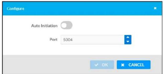
-
Set the Auto Initiation toggle to the right position to enable auto initiation. Set the toggle to the left position to disable auto initiation.
-
If Auto Initiation is enabled, the stream will begin automatically when the receiver subscribes to the transmitter.
-
If Auto Initiation is disabled, the stream will not begin until it is manually initiated.
-
To set the port number, do one of the following:
-
Click the arrows to increase or decrease the port number by increments of 1.
-
Manually enter a port number in the Port field. The default port number is 5004.
-
Click OK to save or click Cancel to cancel the changes.
Routing
The Routing page is used to route a local input, media player, or AES67 stream to a Zone on the DM-NAX-4ZSP.
NOTE: To receive an AES67 stream from Dante devices, see OLH 1001151.
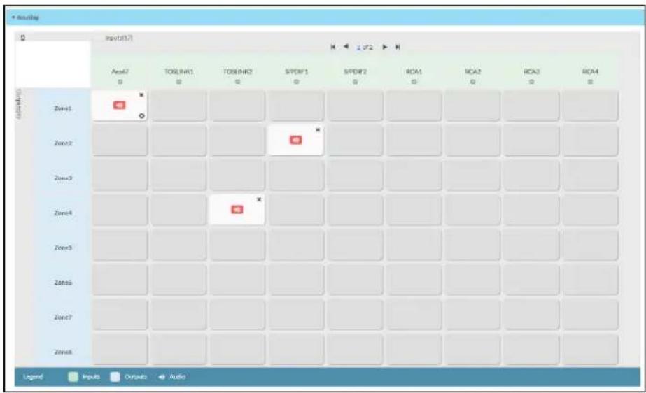
To route an input to a zone, click the box in the routing matrix where the zone's row overlaps the corresponding input's column. Once a route is made, appears. To break a given route click or . To route a single input to all zones, click on the icon under the input's name.
Use the arrows◀ or ▶ at the top of the matrix to change pages to view all available inputs.
To select a specific NAX/AES67 stream when AES67 is selected as the source for a Zone, do the following:
- Click to display the list of all DM NAX/AES67 streams discovered on the network and click a radio button to select the corresponding stream to be routed to the zone.

- Click OK to save or click Cancel to cancel the changes.
Streaming Services
The DM-NAX-4ZSP features four built-in media streaming players, each of which can play back a discrete media stream from a cloud-based service or local casting device. User Profiles can be created for each user of the DM NAX device with discrete credentials, enabling multiple users access to media streaming services without interfering with other users' recommendations, favorites, or playlists.

To configure Streaming Services:
- Click the + Add User Profile button to create a new user profile. Each user profile can contain a unique set of accounts for all supported streaming services.
- Enter a name in the Profile Name field. Click Save to create the User Profile. Once the profile is created, you have the option to either Delete the profile, or add Services to it.
- Click Services in the Action column and an Edit Services window appears.

- Select from the available Streaming Services: TIDAL™, Deezer®, Qobuz®, SOUNDMACHINE®, SiriusXM®, Pandora®, Internet Radio, and Podcasts. Click + or 📋 to add or delete the desired streaming services for each user profile.
User Authentication
User authentication is required for TIDAL, Deezer, Qobuz, SOUNDMACHINE, SiriusXM and Pandora. Click to authorize the user.
To authenticate SiriusXM streaming:
NOTE: To determine whether to use commercial accounts, refer to the streaming service license agreement or FAQs on their respective portals. For SiriusXM, click here.
Enter the user credentials and click OK.

To authenticate TIDAL streaming:
- Click on the link to log in to the TIDAL portal.
NOTE: The link is valid for one minute. After one minute, the link expires, and the Authorize URL is shown as blank. The Authorize User dialogue will need to be closed and reopened.

- Click DONE to return to Streaming Services.
To authenticate Deezer streaming:
- Click on the link to log in to the Deezer portal.
NOTE: The link is valid for one minute. After one minute, the link expires, and the Authorize URL is shown as blank. The Authorize User dialogue will need to be closed and reopened.

- Click DONE to return to Streaming Services.
To authenticate Qobuz streaming:
- Click on the link to log in to the Qobuz portal.
NOTE: The link is valid for one minute. After one minute, the link expires, and the Authorize URL is shown as blank. The Authorize User dialogue will need to be closed and reopened.

- Click DONE to return to Streaming Services.
To authenticate SOUNDMACHINE streaming:
NOTE: To determine whether to use commercial accounts, refer to the streaming service license agreement or FAQs on their respective portals. For SOUNDMACHINE, click here.

- Click the link to log in to the SOUNDMACHINE portal.
NOTE: The link is valid for one minute. After one minute, the link expires, and the Authorize URL is shown as blank. The Authorize User dialogue will need to be closed and reopened.
SOUNDMACHINE
Login
Password
PLEASE ENTER YOUR CREDENTIALS
- Log in to the SOUNDMACHINE account.
- Click DONE to return to Streaming Services.
To authenticate Pandora streaming:
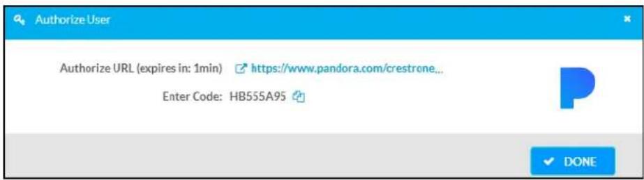
- Click the icon to copy the activation code.
- Click the link to register the device. The Device Activation page is displayed.

NOTE: The link is valid for one minute. After one minute, the link expires, and the Authorize URL and Enter Code are shown as blank. The Authorize User dialogue will need to be closed and reopened.
- Paste the activation code in the Please enter your activation code field and click Activate Now.
- Log in to the Pandora account.
- Click DONE to return to Streaming Services.
Port Selection
The Port Selection feature allows the device's internal network traffic to be managed and segregated based on traffic type. Internal VLANs are used to segment device management and streaming service traffic to a separate physical device Ethernet port than audio-over-IP streaming traffic. With Port Selection enabled on all DM NAX devices on a network, DM NAX and AES67 network traffic can be physically separated from the control network onto a dedicated audio network.
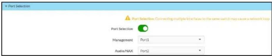
To configure Port Selection:
- Set the Port Selection toggle to the right position to enable Port Selection. Set the toggle to the left position to disable Port Selection. By default, Port Selection is disabled.
NOTE: Ports 1 and 2 correspond to the Ethernet adapters labeled 1 and 2 on the rear panel of the DM-NAX-4ZSP, respectively.
- With Port Selection enabled, select an Ethernet port from the Management drop-down menu to designate which Ethernet port on the rear panel of the device will handle network traffic relating to device configuration, streaming services, and the device's connection to a control system.
NOTES:
- To access streaming services, the Management port must be connected to a network with internet access.
-
The Management port determines your connection to the web interface. Changing the port value can result in losing your connection to the device via the web interface.
-
With Port Selection enabled, select an Ethernet port from the Audio/NAX drop-down menu to designate which Ethernet port on the rear panel of the device will handle audio-over-IP streaming network traffic.
-
Click Save changes to apply the new settings.
NOTE: Making changes to Port Selection settings will require a reboot.
Security
Click the Security tab to configure security for users and groups and to allow different levels of access to the DM-NAX-4ZSP functions. By default, security is disabled.

Select Encrypt and Validate, Encrypt, or OFF in the SSL Mode drop-down menu, to specify whether to use encryption. By default, SSL Mode is set to OFF.
Current User
Click the Current User tab to view read-only information or to change the password for the current user.

- Click the Change Current User Password button to provide a new password for the current user.
- In the Change Password dialog, enter the current password in the Current Password field, the new password in the Password field, and then re-enter the same new password in the Confirm Password field.

- Click OK to save or click Cancel to cancel the changes.
Users
Click the Users tab to view and edit user settings. The Users tab can be used to add or remove local and Active Directory users and preview information about users.

Use the Search Users field to enter search term(s) and display users that match the search criteria.
If users listed in the Users table span across multiple pages, navigate through the list of users by clicking a page number or by using the left or right arrows at the bottom of the Users pane to move forward or backward through the pages.
Each page can be set to display 5, 10, or 20 users by using the drop-down menu to the right of the navigation arrows.
Information about existing users is displayed in table format and the following details are provided for each user.
- Username: Displays the name of the user.
- AD User: Displays whether the user requires authentication using Active Directory.
Click the corresponding button in the Actions column to view detailed user information or to delete the user.
To create a new user, click the Create User button.
Create a New Local User
-
Click the Create User button in the User tab.
-
In the Create User dialog, enter the following:

a. Enter a user name in the Name field. A valid user name can consist of alphanumeric characters (letters a-z, A-Z, numbers 0-9) and the underscore "_" character.
b. Enter a password in the Password field; re-enter the same password in the Confirm Password field.
c. Assign the access level by selecting one or more groups from the Groups drop-down list.
NOTE: Make sure that the Active Directory User toggle is disabled.
- Click OK to save or click Cancel to cancel the changes.
Add an Active Directory User
Users cannot be created or removed from the Active Directory server, but access can be granted to an existing user in the Active Directory server.
To grant access to an Active Directory user, you can either add the user to a local group on the DM-NAX-4ZSP, or add the Active Directory group(s) that they are a member of to the DM-NAX-4ZSP.
To add an Active Directory user.
- Click the Create User button.
- In the Create User dialog, enter the following.

a. Enter a user name in the Name field in the format "Domain\UserName", for example "crestronlabs.com\JohnSmith". Valid user names can contain alphanumeric characters (letters a-z, A-Z, numbers 0-9) and the underscore "_" character.
b. Select one or more groups from the Groups drop-down list.
NOTE: Make sure that the Active Directory User toggle is set to enabled.
- Click OK to save or click Cancel to cancel the changes.
Delete User
Click the trashcan button (☐) in the Actions column to delete the user. Click Yes when prompted to delete the user or No to cancel the deletion.
After a user is removed from a group, they lose any access rights associated with that group. Note that the user account is not deleted by the delete user operation.
View User Details
Click the information button (0) in the Actions column to view information for the selected user. The User Details dialog displays the following information for the selected user.
- Name: Displays the name of the selected user.
• Active Directory User: Displays whether the user is an Active Directory user. - Group: Displays group(s) the selected user is part of.
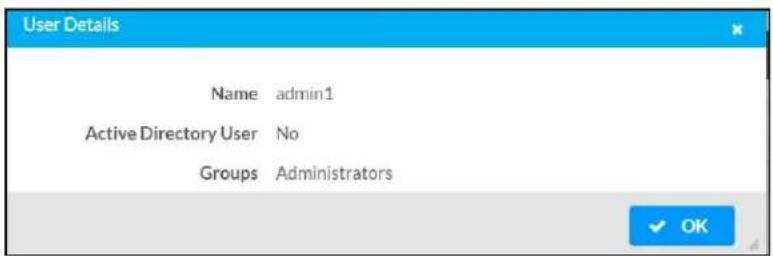
Click OK to close the User Details dialog and to return to the Users tab.
Update User Details

- Click the edit button() in the Actions column to update information for the selected user.
- Enter a password in the Password field; re-enter the same password in the Confirm Password field.
- Select one or more groups to assign the user to from the Groups drop-down list.
- Click OK to save or click Cancel to cancel the changes.
The Update User dialog also displays the following read-only information for the selected user.
• Name: Displays the name of the user.
• Active Directory User: Displays whether the user is an Active Directory user.
Groups
Click the Groups tab to view and edit group settings. The Groups tab can be used to add local and Active Directory groups, remove local and Active Directory groups, and preview information about a group.
Use the Search Groups field to enter search term(s) and display groups that match the search criteria.
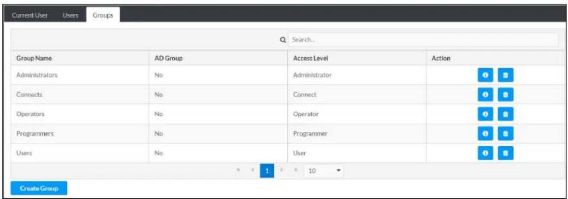
If groups listed in the Groups table span across multiple pages, navigate through the groups by clicking a page number or by using the left or right arrows at the bottom of the Groups pane to move forward or backward through the pages.
Additionally, each page can be set to display 5, 10, or 20 groups by using the drop-down menu to the right of the navigation arrows.
Existing groups are displayed in a table and the following information is provided for each group:
- Group Name: Displays the name of the group.
- AD Group: Displays whether the group requires authentication using Active Directory.
- Access Level: Displays the predefined access level assigned to the group (Administrator, Programmer, Operator, User, or Connect).
Click the corresponding button in the Actions column to view detailed group information (☐) or to delete (☐) selected group.
Click on the Create Group button in the Groups tab to create new group.
Create Local Group

- Click the Create Group button.
- In the Create Group dialog, enter the following:
a. Enter the group name in the Name field.
b. Assign the group access level by selecting a predefined access level (Administrator, Connect, Operator, Programmer, User) from the Access Level drop-down list.
NOTE: Make sure that the Active Directory Group toggle is disabled.
- Click OK to save. Click Cancel to cancel the changes.
Add Active Directory Group
A group cannot be created or removed from the Active Directory server, but access can be granted to a existing group in Active Directory.

Once the group is added, all members of that group will have access to the DM-NAX-4ZSP.
- Click the Create Group button.
- In the Create Group dialog enter the following:
a. Enter the group name in the Name field, for example "Engineering Group". Note that group names are case sensitive; a space is a valid character that can be used in group names.
- Assign the group access level by selecting a predefined access level (Administrator, Connect, Operator, Programmer, User) from the Access Level drop-down list.
NOTE: Make sure that the Active Directory Group toggle is enabled.
- Click OK to save. Click Cancel to cancel the changes.
Delete a Group
Click the trashcan button (☐) in the Actions column to delete a group. Click Yes when prompted to delete the group or No to cancel the deletion.
When a group is deleted, users in the group are not removed from the device or Active Directory server. However, because a user's access level is inherited from a group(s), users within the deleted group will lose access rights associated with the group.
View Group Details
Click the information button (6) in the Actions column to view information for the selected group. The Group Details dialog lists the following information for the selected group.

• Name: Displays the name of the group.
- Access Level: Displays the access level of the group and its users.
• Active Directory Group: Displays whether the group is an Active Directory group.
Click OK to close the Group Details dialog and to return to the Groups tab.
802.1x Configuration
The DM-NAX-4ZSP has built-in support for the 802.1X standard (an IEEE network standard designed to enhance the security of wireless and Ethernet LANs. The standard relies on the exchange of messages between the device and the network's host, or authentication server), allowing communication with the authentication server and access to protected corporate networks.

To Configure DM-NAX-4ZSP for 802.1X Authentication
- Set the IEEE 802.1X Authentication toggle to enabled. This will enable all options on the 802.1X dialog.
- Select the Authentication method: EAP-TLS Certificate or EAP-MSCHAP V2 Password according to the network administrator's requirement.
-
Do either one of the following:
-
Select EAP-TLS Certificate, click Action/Manage Certificates to upload the required machine certificate. The machine certificate is an encrypted file that will be supplied by the network administrator, along with the certificate password.
-
Select EAP-MSCHAP V2 Password, enter the username and password supplied by the network administrator into the Username and Password fields. This method does not require the use of a machine certificate, only the user name and password credentials.
-
If you enabled the Enable Authentication Server Validation option, this will enable the Select Trusted Certificate Authoritie(s) list box which contains signed Trusted Certificate Authorities (CAs) preloaded into the DM-NAX-4ZSP.
Select the check box next to each CA whose certificate can be used for server validation, as specified by the network administrator.
If the network does not use any of the listed certificates, the network administrator must provide a certificate, which must be uploaded manually via the Manage Certificates functionality.
- If required, type the domain name of the network in the Domain field.
- When the 802.1X settings are configured as desired, click Save Changes to save the changes to the device and reboot it. Click Revert to cancel any changes.
Access the Web Interface With the Crestron Toolbox Application
To access the web interface by opening a web browser within the Crestron Toolbox™ application, do the following:
- Open the Crestron Toolbox application.
- From the Tools menu, select Device Discovery Tool. You can also access the Device Discovery Tool by clicking the Device Discovery Tool butt( ) in the Crestron Toolbox toolbar. The DM-NAX-4ZSP is discovered and listed in the device list on the left side of the screen. The associated host name, IP address, and firmware version are also displayed.
NOTE: If there is security software running on the computer, a security alert might be displayed when the Crestron Toolbox application attempts to connect to the network. Make sure to allow the connection, so that the Device Discovery Tool can be used.
- In the Device Discovery Tool list, double-click your device.
- Enter your credentials in the Authentication Required dialog that opens, and then click Log In.
- Click the Web Configuration button in the Configuration page displayed on the left side of the Device Discovery Tool.
DM-NAX-16AIN
This section describes how to configure DM-NAX-16AIN.
Web Interface Configuration
The DM-NAX-16AIN web interface allows you to view status information and configure network and device settings.
Access the Web Interface
To access the web interface, do either of the following:
- Access the Web Interface with a Web Browser on page 376
- Access the Web Interface With the Crestron Toolbox™ Application on page 406
The web interface is accessed from a web browser. The following table lists operating systems and their corresponding supported web browsers.
Operating System and Supported Web Browsers
| OPERATING SYSTEM SUPPORTED WEB BROWSERS | |
| Windows® operating system | ChromeTM web browser, version 31 and laterFirefox® web browser, version 31 and laterInternet Explorer web browser, version 11 and laterMicrosoft Edge web browser |
| macOS® operating system | Safari® web browser, version 6 and laterChrome web browser, version 31 and laterFirefox web browser, version 31 and later |
Access the Web Interface with a Web Browser
- Enter the IP address of the DM-NAX-16AIN into a web browser.
NOTE: To obtain the IP address, use the Device Discovery Tool option in Crestron Toolbox™ application or an IP scanner application.
- If you are creating a user account for the first time, do the following; otherwise, skip to step 3.
a. Enter a username in the Username field.
b. Enter a password in the Password field.
c. Re-enter the same password in the Confirm Password field.

d. Click Create User. The Device Administration page appears.

- Enter the username in the Username field.
- Enter the password in the Password field.
- Click Sign In.
Action
The Action drop-down menu is displayed at the top right side of the interface and provides quick access to common device functions:
- Save Changes
- Revert
- Reboot
- Restore
- Update Firmware
- Download Logs
- Manage Certificates

Save Changes
Click Save Changes to save any changes made to the configuration settings.
Revert
Click Revert to revert the device back to the last saved configuration settings.
Reboot the DM-NAX-16AIN
Certain changes to the settings may require the DM-NAX-16AIN to be rebooted to take effect. To reboot the device, do the following:
- Click Reboot in the Actions drop-down menu. The Confirmation message box appears.

- Click Yes, Reboot Now to reboot the device. The Reboot message box appears.
Wait for the device reboot to complete before attempting to reconnect to the device.
Restore to Factory Default Settings
- Click Restore in the Actions drop-down menu to restore the settings of the DM-NAX-16AIN to factory defaults.
NOTE: When settings are restored, all settings, including the network settings, will revert to the factory default. If a static IP address is set, restoring the device to factory default settings will revert the IP address to the default DHCP mode.
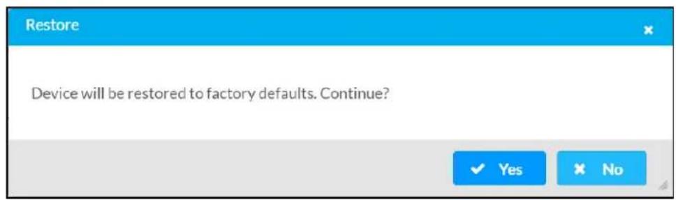
- Click Yes in the Confirmation dialog to restore the DM-NAX-16AIN to factory settings. Click No to cancel the restore operation.
A dialog is displayed again, indicating that the restore process was successful and that the device rebooted.
You can also restore to factory settings by pressing and holding the SETUP button on the rear panel of the device with power disconnected then connect the power supply and continue to hold SETUP button for 30 seconds.
Update Firmware
-
Click Update Firmware in the Actions drop-down menu.
-
In the Firmware Upgrade dialog, click + Browse.
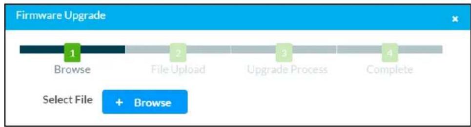
-
Locate and select the desired firmware file, and then click Open. The selected firmware file name is displayed in the Firmware Upgrade dialog.
-
Click Load and wait for the progress bar to complete and for the OK button in the message to become clickable.
-
Click OK. The device with new firmware can now be accessed.
Download Logs
- Click Download Logs in the Actions drop-down menu to download the device message logs for diagnostic purposes.
The log file is downloaded to the Downloads folder of the PC.
Manage Certificates
Use the Manage Certificates dialog to add, remove, and manage certificates used in 802.1x and other protected networks.

-
Click Manage Certificates in the Actions drop-down menu. The following certificate tabs are displayed:
-
Root: The Root certificate is used by the DM-NAX-16AIN to validate the network's authentication server. The DM-NAX-16AIN has a variety of Root certificates, self-signed by trusted CAs (Certificate Authorities) preloaded into the device. Root certificates must be self-signed.
- Intermediate: The Intermediate store holds non self-signed certificates that are used to validate the authentication server. These certificates will be provided by the network administrator if the network does not use self-signed Root certificates.
- Machine: The machine certificate is an encrypted PFX file that is used by the authentication server to validate the identity of the DM-NAX-16AIN. The machine certificate will be provided by the network administrator, along with the certificate password. For 802.1x, only one machine certificate can reside on the device.
- Web Server: The Web Server certificate is a digital file that contains information about the identity of the web server.
To Add Certificates
-
Click the corresponding certificate tab.
-
Click the Add Root Certificate button.
-
Click the + Browse button.
-
Locate and select the file, and then click the Open button.
NOTE: If the certificate is a Machine Certificate, enter the password provided by the network administrator.
- Click OK. This will add the certificate to the list box, displaying the file name and expiration date. The certificate is now available for selection and can be loaded to the device.
To Delete Certificates
-
Click the corresponding certificate tab.
-
Click the trashcan button ( ) in the Actions column to delete the certificate.
-
Click Yes when prompted to delete the certificate or No to cancel the deletion.
Status
The Status tab is the first page displayed when opening the interface of the DM-NAX-16AIN. It displays general information about the DM-NAX-16AIN (such as Model Name, Firmware Version, and Serial Number) and current network settings (such as Host Name and IP Address, etc.).
The Status tab can be accessed at any time by clicking the Status tab of the DM-NAX-16AIN interface.

Information displayed on the Status tab is organized into different sections.
Device
The Device section displays the Model, Firmware Version, and Serial Number of the DM-NAX-16AIN.
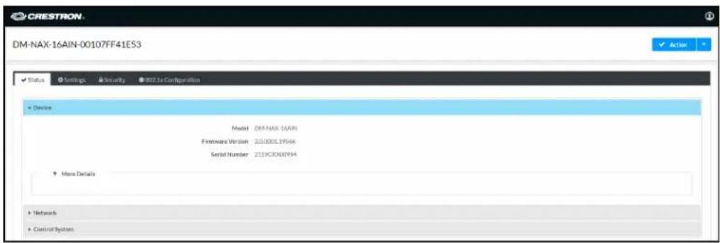
Click + More Details to review additional information about the DM-NAX-16AIN.
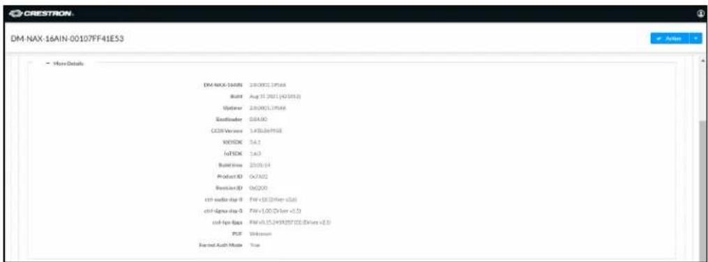
Network
The Network section displays network-related information about the DM-NAX-16AIN, including the Hostname, Domain Name, and DNS Servers.

NOTE: By default, the host name of the DM-NAX-16AIN consists of the model name followed by the MAC address of the device. For example, DM-NAX-16AIN-00107FF41E53.
Click + Adapter 1 to display an expanded section that shows additional information. If + Adapter 1 is selected, click - Less details to collapse the section.
NOTE: The + Adapter 2 option appears when the dual Ethernet ports on the DM-NAX-16AIN are set to isolate traffic using the Port Selection feature.
Control System
The Control System section displays connection information, consisting of the following:

- Encrypt Connection: ON or OFF
• IP ID: Reports the currently used IP ID of the DM-NAX-16AIN
• IP Address/Hostname: The IP address of the control system
• Room ID: Displays the room ID
• Status: OFFLINE or ONLINE
Settings
The Settings tab enables you to configure the DM-NAX-16AIN settings. The Settings page can be accessed at any time by clicking the Settings tab of the DM-NAX-16AIN interface.
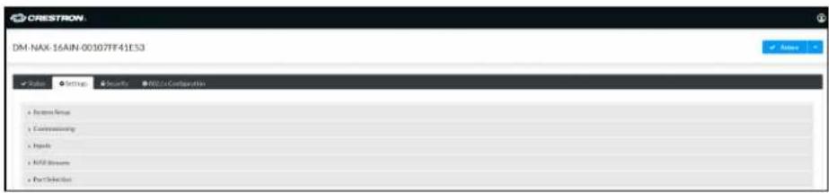
Settings available on the Settings tab are organized into different sections.
System Setup
The System Setup section contains settings for Date/Time, Auto Update, Network, and Control System.
Date/Time
Use the Date/Time section to configure the date and time settings of the DM-NAX-16AIN.

Time Synchronization
- Set the Time Synchronization toggle to the right position to enable or left position to disable time synchronization. By default, time synchronization is enabled.
- In the NTP Time Servers table, enter the URL of a NTP (Network Time Protocol) or SNTP (Simple Network Time Protocol) server. Up to three time servers can be added on a device.
- Click Synchronize Now to perform time synchronization between the device's internal clock and the time server.
Time Configuration
- Click on the Time Zone drop-down menu to select the applicable time zone.
- In the Date field, enter the current date.
- In the Time (24hr Format) field, enter the current time in 24-hour format.
Click the Save Changes button to save the settings.
Click Revert from the Actions drop-down menu to revert to the previous settings without saving.
Auto Update
The DM-NAX-16AIN can automatically check for and install firmware updates at scheduled intervals via the Auto Update feature.

- Set the Auto Update toggle to the right position to enable Auto Update.
- Define the URL to download the updates by doing either of the following:
a. Use the default URL to download the updates from the Crestron server.
b. Use a custom URL. Set the Custom URL toggle to the right position to enable a custom URL. In the Custom URL Path text box, enter the path to a custom manifest file in the F or SFTP URL format. Use the Crestron Auto Update Tool to generate a custom manifest file, then store the file on an FTP (File Transfer Protocol) or SFTP (Secure File Transfer Protocol) server.
- Set a schedule for the automatic firmware update by doing either of the following:
a. Select the desired Day of Week and Time of Day (24-hour format) values.
b. Set the Poll Interval by entering a value from 60 to 65535 minutes. A value of 0 disables the Poll Interval.
- Click Save Changes.
Clicking Update Now causes the device to check for a firmware update immediately. If a schedule was set in step 4 above, that schedule still remains in effect.
Network
The Network section contains network-related settings for the DM-NAX-16AIN, including the Hostname, Domain, Primary Static DNS, and Secondary Static DNS.
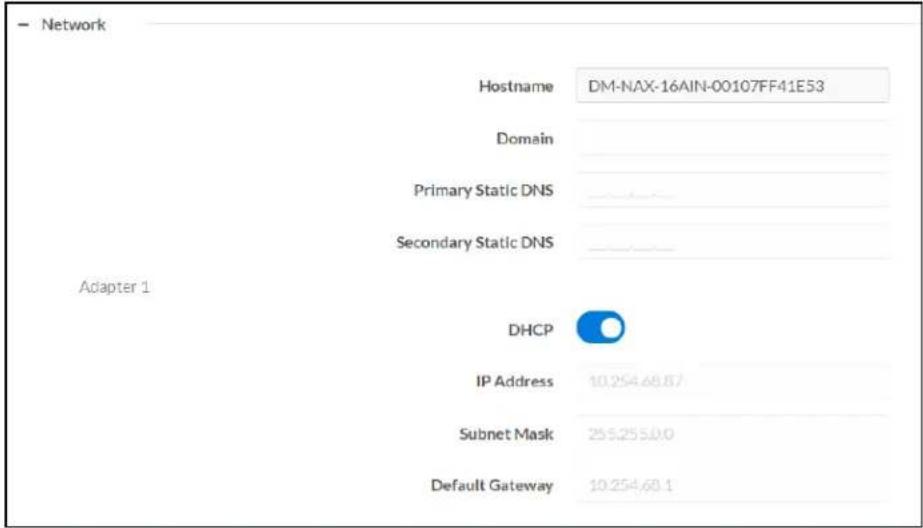
NOTE: By default, the hostname of the DM-NAX-16AIN consists of the model name followed by the MAC address of the device. For example, DM-NAX-16AIN-00107FB58088.
Adapter 1
The Adapter 1 subheading contains settings for DHCP, IP Address, Subnet Mask, and Default Gateway of Ethernet adapter 1 on the rear panel of the device.
NOTES:
- An + Adapter 2 option only appears when the dual Ethernet ports on the DM-NAX-8ZSA are set to isolate traffic using the Port Selection feature. The settings for Adapter 2 are identical to those available for Adapter 1.
- DM NAX devices' internal processes use IP addresses in the 10x10 range. This IP range should be avoided when addressing DM NAX devices to prevent conflicts.
Set the DHCP toggle to enabled (right) or disabled (left) to specify whether the IP address of the DM-NAX-16AIN is to be assigned by a DHCP (Dynamic Host Configuration Protocol) server.
- Enabled: When DHCP is enabled (default setting), the IP address of the DM-NAX-16AIN is automatically assigned by a DHCP server on the local area network (LAN).
-
Disabled: When DHCP is disabled, manually enter information in the following fields:
-
Primary Static DNS: Enter a primary DNS IP address.
Secondary Static DNS: Enter a secondary DNS IP address. - IP Address: Enter a unique IP address for the DM-NAX-16AIN.
- Subnet Mask: Enter the subnet mask that is set on the network.
Default Gateway: Enter the IP address that is to be used as the network's gateway.
To save any new network entries, click Save Changes.
Control System

- Click the Encrypt Connection button to navigate to the Security tab to configure encryption settings.
- Enter the username in the Control System Username field.
- Enter the password in the Control System Password field.
- Enter the Room ID in the Room ID field.
- Enter the IP ID of the DM-NAX-16AIN in the IP ID field.
- Enter the IP address or hostname of the control system in the IP Address/Hostname field.
- Click the Save Changes button to save the new entries. The Control System Save message box appears, indicating that the control system settings were saved successfully. Click the Revert button to revert to the previous settings without saving.
Commissioning
The Commissioning section provides a quick way to automatically assign multicast addresses to all of the device's internal audio-over-IP stream transmitters.
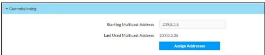
Click Assign Addresses to give each DM NAX transmitter in the DM-NAX-16AIN a unique multicast address beginning with the specified Starting Multicast Address. The valid range for Starting Multicast Address is 239.8.0.0 to 239.255.255.239.
NOTE: This will begin transmitting multicast traffic on your network, refer to the DM NAX Audio-over-IP System Design Guide document for details.
Inputs
The Inputs menu is used to configure Name, Compensation, and Mute attributes of the available analog and digital inputs on the DM-NAX-16AIN.

flowchart
graph TD
    A["Inputs (Autosaved)"] --> B["Gain (db)"]
    B --> C["Signal Present"]
    C --> D["Clipping Detected"]
    D --> E["Mute"]
    A --> F["TOSLINK1"]
    A --> G["TOSLINK2"]
    A --> H["S/PDIF1"]
    A --> I["S/PDIF2"]
    A --> J["RCA1"]
    A --> K["RCA2"]
    A --> L["RCA3"]
    A --> M["RCA4"]
    F --> N["0"]
    G --> O["0"]
    H --> P["0"]
    I --> Q["0"]
    J --> R["0"]
    K --> S["0"]
    L --> T["0"]
    M --> U["0"]
    N --> V["OK"]
    O --> W["OK"]
    P --> X["OK"]
    Q --> Y["OK"]
    R --> Z["OK"]
    S --> AA["OK"]
    T --> AB["OK"]
    U --> AC["OK"]
    V --> AD["OK"]
    W --> AE["OK"]
    X --> AF["OK"]
    Y --> AG["OK"]
    Z --> AH["OK"]
    AA --> AI["OK"]
    AB --> AJ["OK"]
    AC --> AK["OK"]
    AD --> AL["OK"]
    AE --> AM["OK"]
    AF --> AN["OK"]
    AG --> AO["OK"]
    AH --> AP["OK"]
    AI --> AQ["OK"]
    AJ --> AR["OK"]
    AK --> AS["OK"]
    AL --> AT["OK"]
    AM --> AU["OK"]
    AN --> AV["OK"]
    AO --> AW["OK"]
    AP --> AX["OK"]
    AQ --> AY["OK"]
Configure Inputs
- If needed, enter a friendly name for each input in its Name field.
- To set a level compensation adjustment for a given input, do one of the following:
- Move the Compensation slider up to increase or down to decrease the compensation.
Compensation increases the level of the incoming audio signal on any of the physical inputs on the device's rear panel.
- Click the db arrows to increase or decrease the compensation. Values range from -10 dB to 10 dB, adjustable in increments of 1 dB.
-
Manually enter a value in the Compensation field.
-
To mute the signal from the corresponding input, click the Mute button. To disable the mute, click the Muted button. By default, Mute is disabled.
Monitor the device's input signals using the text indicators in the Signal Present and Clipping Detected columns:
• Signal Presence indicates whether or not a signal is detected in that zone.
- Clipping Detected indicates if the signal is Clipping or Nominal (non-clipping).
Use the Global Filter text field to filter specific inputs by name. Not all of the available inputs are shown on the first page in this section when no Global Filter is applied. Use ▶ at the bottom of the table to view the next page of inputs.
DM NAX Streams
Each local input of the DM-NAX-8ZSA can be made available as a DM NAX audio-over-IP stream.
Click NAX Streams to display the following information.
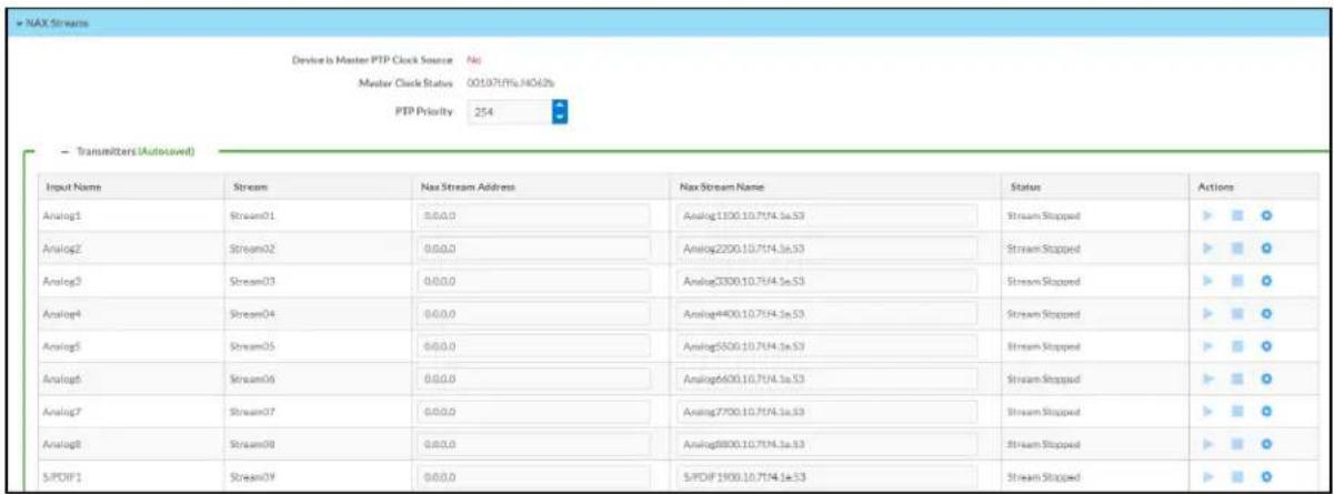
- Device is Master PTP Clock Source indicates whether the device is the master for PTP on the network. Yes will be displayed in green when the local DM-NAX-16AIN is the PTP clock master and No will be displayed in red when another PTP clock on the network is operating as the master clock.
- Master Clock Status displays the Master Clock ID of the device on the network that acts as the Master Clock.
- PTP Priority: This sets the priority of the local DM NAX device's PTP clock relative to other clocks on the network. The default setting is 254 (one increment higher than the lowest possible value) so that the DM-NAX-16AIN will only operate as clock master if no other PTP master is present on the network. Valid values range from 1 to 255.
Configure Transmitters
| Input Name | Stream | Nas Stream Address | Nas Stream Name | Status | Actions |
| Analog1 | Stream01 | 0.0.0.0 | Analog1100.10.7IF4.1e.53 | Stream Stopped | |
| Analog2 | Stream02 | 0.0.0.0 | Analog2200.10.7IF4.1e.53 | Stream Stopped | |
| Analog3 | Stream03 | 0.0.0.0 | Analog3000.10.7IF4.1e.53 | Stream Stopped | |
| Analog4 | Stream04 | 0.0.0.0 | Analog4400.10.7IF4.1e.53 | Stream Stopped | |
| Analog5 | Stream05 | 0.0.0.0 | Analog5500.10.7IF4.1e.53 | Stream Stopped | |
| Analog6 | Stream06 | 0.0.0.0 | Analog6600.10.7IF4.1e.53 | Stream Stopped | |
| Analog7 | Stream07 | 0.0.0.0 | Analog7700.10.7IF4.1e.53 | Stream Stopped | |
| Analog8 | Stream08 | 0.0.0.0 | Analog8800.10.7IF4.1e.53 | Stream Stopped | |
| S/PDF1 | Stream09 | 0.0.0.0 | S/PDF1900.10.7IF4.1e.53 | Stream Stopped | |
| S/PDF2 | Stream10 | 0.0.0.0 | S/PDF21000.10.7IF4.1e.53 | Stream Stopped |
NOTE: To configure transmitters not shown on the current page of the table, click the icon to display the next page of eight transmitters.
To configure a DM NAX transmit stream, do the following.
-
Enter a valid multicast address in the NAX Stream Address field.
-
Enter a name in the NAX Stream Name field by which the stream can be identified. This stream name is associated with the DM NAX stream's multicast address by other DM NAX or AES67 devices, like a device hostname that resolves to a given IP address.
-
Status indicates whether a stream is transmitting or not. When the stream has started or stopped, the Status column will update accordingly.
-
Click the configure button (💡) in the Actions column. The Configure dialog appears:

-
Set the Auto Initiation toggle to the right position to enable auto initiation. Set the toggle to the left position to disable auto initiation.
-
If Auto Initiation is enabled for a given stream, the stream will begin transmitting automatically and will be available as a multicast stream on your network at the specified multicast address.
-
If Auto Initiation is disabled for the input, the stream will not begin transmitting until it is manually initiated.
-
To set the port number, do one of the following:
-
Click the arrows to increase or decrease the port number by increments of 1.
-
Manually enter a port number in the Port field. The default port number for DM NAX streams is 5004.
-
Click OK to save or click Cancel to cancel the changes.
Port Selection
The Port Selection feature allows the device's internal network traffic to be managed and segregated based on traffic type. Internal VLANs are used to segment device management and streaming service traffic to a separate physical device Ethernet port than audio-over-IP streaming traffic. With Port Selection enabled on all DM NAX devices on a network, DM NAX and AES67 network traffic can be physically separated from the control network onto a dedicated audio network.

To configure Port Selection:
- Set the Port Selection toggle to the right position to enable Port Selection. Set the toggle to the left position to disable Port Selection. By default, Port Selection is disabled.
NOTE: Ports 1 and 2 correspond to the Ethernet adapters labeled 1 and 2 on the rear panel of the DM-NAX-16AIN, respectively.
- With Port Selection enabled, select an Ethernet port from the Management drop-down menu to designate which Ethernet port on the rear panel of the device will handle network traffic relating to device configuration and the device's connection to a control system.
NOTE: The Management port controls your connection to the web interface. Changing the port value can result in losing your connection to the device via the web interface.
-
With Port Selection enabled, select an Ethernet port from the Audio/NAX drop-down menu to designate which Ethernet port on the rear panel of the device will handle audio-over-IP streaming network traffic.
-
Click Save changes to apply the new settings.
NOTE: Making changes to Port Selection settings will require a reboot.
Security
Click the Security tab to configure security for users and groups and to allow different levels of access to the DM-NAX-16AIN functions. By default, security is disabled.

Select Encrypt and Validate, Encrypt, or OFF in the SSL Mode drop-down menu, to specify whether to use encryption. By default, SSL Mode is set to OFF.
Current User
Click the Current User tab to view read-only information or to change the password for the current user.
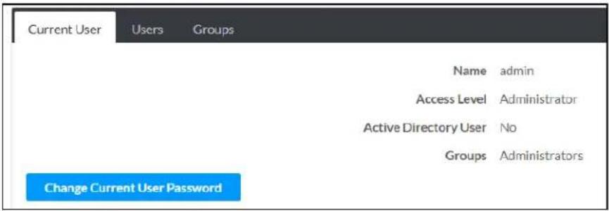
- Click the Change Current User Password button to provide a new password for the current user.
- In the Change Password dialog, enter the current password in the Current Password field, the new password in the Password field, and then re-enter the same new password in the Confirm Password field.
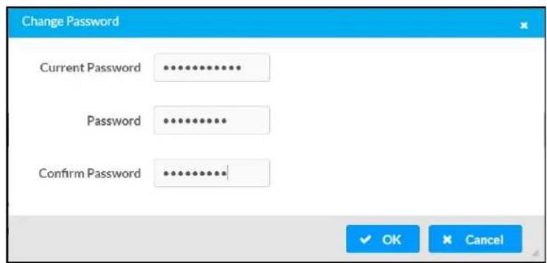
- Click OK to save or click Cancel to cancel the changes.
Users
Click the Users tab to view and edit user settings. The Users tab can be used to add or remove local and Active Directory users and preview information about users.

Use the Search Users field to enter search term(s) and display users that match the search criteria.
If users listed in the Users table span across multiple pages, navigate through the list of users by clicking a page number or by using the left or right arrows at the bottom of the Users pane to move forward or backward through the pages.
Each page can be set to display 5, 10, or 20 users by using the drop-down menu to the right of the navigation arrows.
Information about existing users is displayed in table format and the following details are provided for each user.
- Username: Displays the name of the user.
- AD User: Displays whether the user requires authentication using Active Directory.
Click the corresponding button in the Actions column to view detailed user information or to delete the user.
To create a new user, click the Create User button.
Create a New Local User
-
Click the Create User button in the User tab.
-
In the Create User dialog, enter the following:

a. Enter a user name in the Name field. A valid user name can consist of alphanumeric characters (letters a-z, A-Z, numbers 0-9) and the underscore "_" character.
b. Enter a password in the Password field; re-enter the same password in the Confirm Password field.
c. Assign the access level by selecting one or more groups from the Groups drop-down list.
NOTE: Make sure that the Active Directory User toggle is disabled.
- Click OK to save or click Cancel to cancel the changes.
Add an Active Directory User
Users cannot be created or removed from the Active Directory server, but access can be granted to an existing user in the Active Directory server.
To grant access to an Active Directory user, you can either add the user to a local group on the DM-NAX-16AIN, or add the Active Directory group(s) that they are a member of to the DM-NAX-16AIN.
To add an Active Directory user.
- Click the Create User button.
- In the Create User dialog, enter the following.

a. Enter a user name in the Name field in the format "Domain\UserName", for example "crestronlabs.com\JohnSmith". Valid user names can contain alphanumeric characters (letters a-z, A-Z, numbers 0-9) and the underscore "_" character.
b. Select one or more groups from the Groups drop-down list.
NOTE: Make sure that the Active Directory User toggle is set to enabled.
- Click OK to save or click Cancel to cancel the changes.
Delete User
Click the trashcan button (☐) in the Actions column to delete the user. Click Yes when prompted to delete the user or No to cancel the deletion.
After a user is removed from a group, they lose any access rights associated with that group. Note that the user account is not deleted by the delete user operation.
View User Details
Click the information button (0) in the Actions column to view information for the selected user. The User Details dialog displays the following information for the selected user.
- Name: Displays the name of the selected user.
• Active Directory User: Displays whether the user is an Active Directory user. - Group: Displays group(s) the selected user is part of.

Click OK to close the User Details dialog and to return to the Users tab.
Update User Details
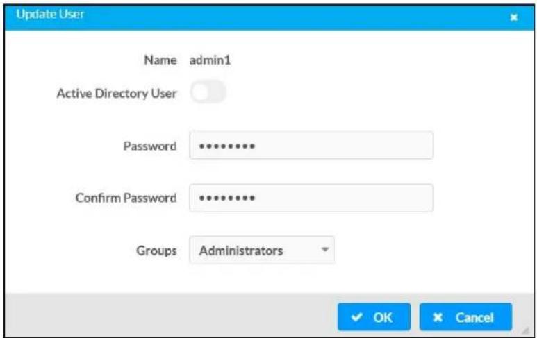
- Click the edit button() in the Actions column to update information for the selected user.
- Enter a password in the Password field; re-enter the same password in the Confirm Password field.
- Select one or more groups to assign the user to from the Groups drop-down list.
- Click OK to save or click Cancel to cancel the changes.
The Update User dialog also displays the following read-only information for the selected user.
• Name: Displays the name of the user.
• Active Directory User: Displays whether the user is an Active Directory user.
Groups
Click the Groups tab to view and edit group settings. The Groups tab can be used to add local and Active Directory groups, remove local and Active Directory groups, and preview information about a group.
Use the Search Groups field to enter search term(s) and display groups that match the search criteria.

If groups listed in the Groups table span across multiple pages, navigate through the groups by clicking a page number or by using the left or right arrows at the bottom of the Groups pane to move forward or backward through the pages.
Additionally, each page can be set to display 5, 10, or 20 groups by using the drop-down menu to the right of the navigation arrows.
Existing groups are displayed in a table and the following information is provided for each group:
- Group Name: Displays the name of the group.
- AD Group: Displays whether the group requires authentication using Active Directory.
- Access Level: Displays the predefined access level assigned to the group (Administrator, Programmer, Operator, User, or Connect).
Click the corresponding button in the Actions column to view detailed group information (☐) or to delete ☐ selected group.
Click on the Create Group button in the Groups tab to create new group.
Create Local Group
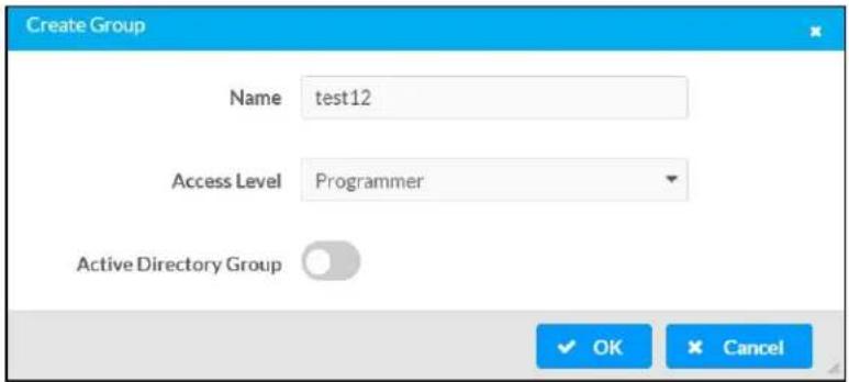
- Click the Create Group button.
- In the Create Group dialog, enter the following:
a. Enter the group name in the Name field.
b. Assign the group access level by selecting a predefined access level (Administrator, Connect, Operator, Programmer, User) from the Access Level drop-down list.
NOTE: Make sure that the Active Directory Group toggle is disabled.
- Click OK to save. Click Cancel to cancel the changes.
Add Active Directory Group
A group cannot be created or removed from the Active Directory server, but access can be granted to a existing group in Active Directory.

Once the group is added, all members of that group will have access to the DM-NAX-16AIN.
- Click the Create Group button.
- In the Create Group dialog enter the following:
a. Enter the group name in the Name field, for example "Engineering Group". Note that group names are case sensitive; a space is a valid character that can be used in group names.
- Assign the group access level by selecting a predefined access level (Administrator, Connect, Operator, Programmer, User) from the Access Level drop-down list.
NOTE: Make sure that the Active Directory Group toggle is enabled.
- Click OK to save. Click Cancel to cancel the changes.
Delete a Group
Click the trashcan button (☐) in the Actions column to delete a group. Click Yes when prompted to delete the group or No to cancel the deletion.
When a group is deleted, users in the group are not removed from the device or Active Directory server. However, because a user's access level is inherited from a group(s), users within the deleted group will lose access rights associated with the group.
View Group Details
Click the information button (6) in the Actions column to view information for the selected group. The Group Details dialog lists the following information for the selected group.

• Name: Displays the name of the group.
- Access Level: Displays the access level of the group and its users.
• Active Directory Group: Displays whether the group is an Active Directory group.
Click OK to close the Group Details dialog and to return to the Groups tab.
802.1x Configuration
The DM-NAX-16AIN has built-in support for the 802.1X standard (an IEEE network standard designed to enhance the security of wireless and Ethernet LANs. The standard relies on the exchange of messages between the device and the network's host, or authentication server), allowing communication with the authentication server and access to protected corporate networks.
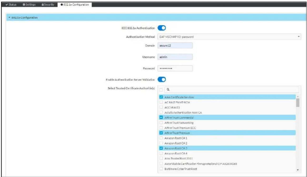
To Configure DM-NAX-16AIN for 802.1X Authentication
- Set the IEEE 802.1X Authentication toggle to enabled. This will enable all options on the 802.1X dialog.
-
Select the Authentication method: EAP-TLS Certificate or EAP-MSCHAP V2 Password according to the network administrator's requirement.
-
Do either one of the following:
-
Select EAP-TLS Certificate, click Action/Manage Certificates to upload the required machine certificate. The machine certificate is an encrypted file that will be supplied by the network administrator, along with the certificate password.
-
Select EAP-MSCHAP V2 Password, enter the username and password supplied by the network administrator into the Username and Password fields. This method does not require the use of a machine certificate, only the user name and password credentials.
-
If you enabled the Enable Authentication Server Validation option, this will enable the Select Trusted Certificate Authoritie(s) list box which contains signed Trusted Certificate Authorities (CAs) preloaded into the DM-NAX-16AIN.
Select the check box next to each CA whose certificate can be used for server validation, as specified by the network administrator.
If the network does not use any of the listed certificates, the network administrator must provide a certificate, which must be uploaded manually via the Manage Certificates functionality.
-
If required, type the domain name of the network in the Domain field.
-
When the 802.1X settings are configured as desired, click Save Changes to save the changes to the device and reboot it. Click Revert to cancel any changes.
Access the Web Interface With the Crestron Toolbox Application
To access the web interface by opening a web browser within the Crestron Toolbox™ application, do the following:
- Open the Crestron Toolbox application.
- From the Tools menu, select Device Discovery Tool. You can also access the Device Discovery Tool by clicking the Device Discovery Tool butt( ) in the Crestron Toolbox toolbar. The DM-NAX-16AIN is discovered and listed in the device list on the left side of the screen. The associated host name, IP address, and firmware version are also displayed.
NOTE: If there is security software running on the computer, a security alert might be displayed when the Crestron Toolbox application attempts to connect to the network. Make sure to allow the connection, so that the Device Discovery Tool can be used.
- In the Device Discovery Tool list, double-click your device.
- Enter your credentials in the Authentication Required dialog that opens, and then click Log In.
- Click the Web Configuration button in the Configuration page displayed on the left side of the Device Discovery Tool.
DM-NAX-AMP-X300
This section describes how to configure the DM-NAX-AMP-X300.
Web Interface Configuration
The DM-NAX-AMP-X300 web interface allows you to view status information and configure network and device settings.
NOTE: Throughout the web interface, values can be entered manually. When values entered manually fall out of the range, the value will be maximized or minimized or have no effect.
Access the Web Interface
To access the web interface, do either of the following:
- Access the Web Interface with a Web Browser on page 408
- Access the Web Interface With the Crestron Toolbox™ Application on page 472
The web interface is accessed from a web browser. The following table lists operating systems and their corresponding supported web browsers.
Operating System and Supported Web Browsers
| OPERATING SYSTEM SUPPORTED WEB BROWSERS | |
| Windows® operating system | ChromeTM web browser, version 31 and laterFirefox® web browser, version 31 and laterInternet Explorer web browser, version 11 and laterMicrosoft Edge web browser |
| macOS® operating system | Safari® web browser, version 6 and laterChrome web browser, version 31 and laterFirefox web browser, version 31 and later |
Access the Web Interface with a Web Browser
- Enter the IP address of the DM-NAX-AMP-X300 into a web browser.
NOTE: To obtain the IP address, use the Device Discovery Tool option in Crestron Toolbox™ application or an IP scanner application.
- If you are creating a user account for the first time, do the following; otherwise, skip to step 3.
a. Enter a username in the Username field.
b. Enter a password in the Password field.
c. Re-enter the same password in the Confirm Password field.
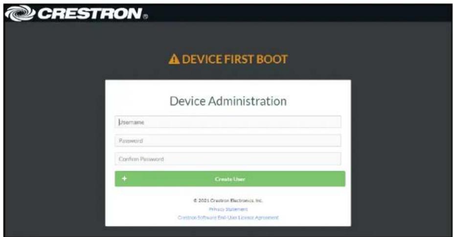
d. Click Create User. The Device Administration page appears.
- Enter the username in the Username field.
- Enter the password in the Password field.
- Click Sign In.
Action
The Action drop-down menu is displayed at the top right side of the interface and provides quick access to common device functions:
- Save Changes
- Revert
- Reboot
- Restore
- Update Firmware
- Download Logs
- Manage Certificates
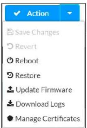
Save Changes
Click Save Changes to save any changes made to the configuration settings.
Revert
Click Revert to revert the device back to the last saved configuration settings.
Reboot the DM-NAX-AMP-X300
Certain changes to the settings may require the DM-NAX-AMP-X300 to be rebooted to take effect. To reboot the device, do the following:
- Click Reboot in the Actions drop-down menu. The Confirmation message box appears.

- Click Yes, Reboot Now to reboot the device. The Reboot message box appears.
Wait for the device reboot to complete before attempting to reconnect to the device.
Restore to Factory Default Settings
- Click Restore in the Actions drop-down menu to restore the settings of the DM-NAX-AMP-X300 to factory defaults.
NOTE: When settings are restored, all settings, including the network settings, will revert to the factory default. If a static IP address is set, restoring the device to factory default settings will revert the IP address to the default DHCP mode.

- Click Yes in the Confirmation dialog to restore the DM-NAX-AMP-X300 to factory settings. Click No to cancel the restore operation.
A dialog is displayed again, indicating that the restore process was successful and that the device rebooted.
You can also restore the device by following the Reset procedures in the DM-NAX-AMP-X300 Installation on page 105 section of this manual.
Update Firmware
-
Click Update Firmware in the Actions drop-down menu.
-
In the Firmware Upgrade dialog, click + Browse.

-
Locate and select the desired firmware file, and then click Open. The selected firmware file name is displayed in the Firmware Upgrade dialog.
-
Click Load and wait for the progress bar to complete and for the OK button in the message to become clickable.
-
Click OK. The device with new firmware can now be accessed.
Download Logs
- Click Download Logs in the Actions drop-down menu to download the device message logs for diagnostic purposes.
The log file is downloaded to the Downloads folder of the PC.
Manage Certificates
Use the Manage Certificates dialog to add, remove, and manage certificates used in 802.1x and other protected networks.

-
Click Manage Certificates in the Actions drop-down menu. The following certificate tabs are displayed:
-
Root: The Root certificate is used by the DM-NAX-AMP-X300 to validate the network's authentication server. The DM-NAX-AMP-X300 has a variety of Root certificates, self-signed by trusted CAs (Certificate Authorities) preloaded into the device. Root certificates must be self-signed.
- Intermediate: The Intermediate store holds non self-signed certificates that are used to validate the authentication server. These certificates will be provided by the network administrator if the network does not use self-signed Root certificates.
- Machine: The machine certificate is an encrypted PFX file that is used by the authentication server to validate the identity of the DM-NAX-AMP-X300. The machine certificate will be provided by the network administrator, along with the certificate password. For 802.1x, only one machine certificate can reside on the device.
- Web Server: The Web Server certificate is a digital file that contains information about the identity of the web server.
To Add Certificates
-
Click the corresponding certificate tab.
-
Click the Add Root Certificate button.
-
Click the + Browse button.
-
Locate and select the file, and then click the Open button.
NOTE: If the certificate is a Machine Certificate, enter the password provided by the network administrator.
- Click OK. This will add the certificate to the list box, displaying the file name and expiration date. The certificate is now available for selection and can be loaded to the device.
To Delete Certificates
-
Click the corresponding certificate tab.
-
Click the trashcan button ( ) in the Actions column to delete the certificate.
-
Click Yes when prompted to delete the certificate or No to cancel the deletion.
Status
The Status tab is the first page displayed when opening the interface of the DM-NAX-AMP-X300. It displays general information about the DM-NAX-AMP-X300 (such as Model Name, Firmware Version, and Serial Number), current network settings (such as Host Name and IP Address, etc.), and input and output ports' current status.
The Status tab can be accessed at any time by clicking the Status tab of the DM-NAX-AMP-X300 interface.
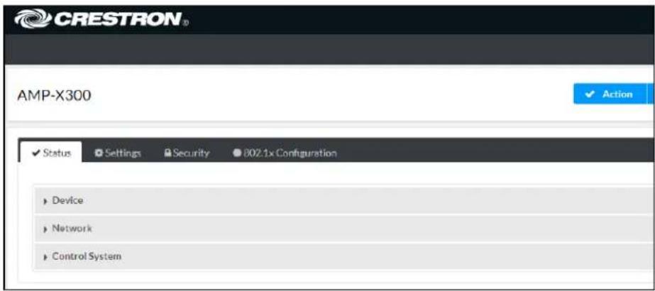
Information displayed on the Status tab is organized into different sections.
Device
The Device section displays the Model, Firmware Version, and Serial Number of the DM-NAX-AMP-X300.

Click + More Details to review additional information about the DM-NAX-AMP-X300.
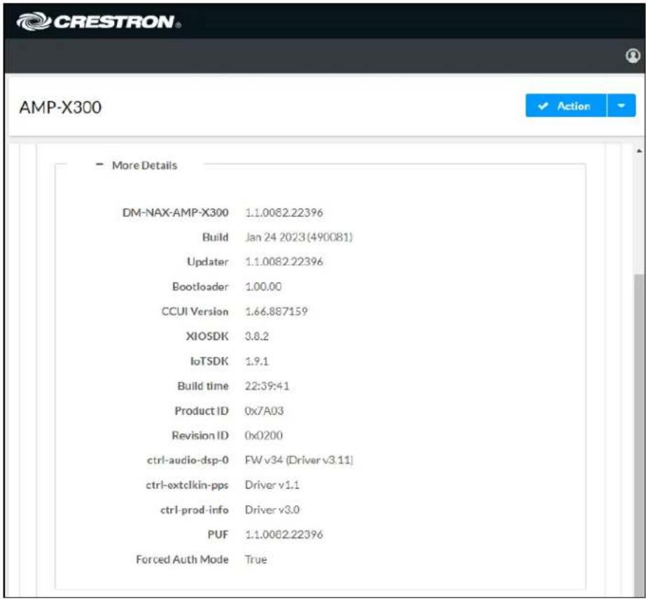
Network
The Network section displays network-related information about the DM-NAX-AMP-X300, including the Hostname, Domain Name, and DNS Servers.

NOTE: By default, the host name of the DM-NAX-AMP-X300 consists of the model name followed by the MAC address of the device. For example, DM-NAX-AMP-X300-00107FB58088.
Click + Adapter 1 to display an expanded section that shows additional information. If + Adapter 1 is selected, click - Less details to collapse the section.
NOTE: The + Adapter 2 option appears when the dual Ethernet ports on the DM-NAX-AMP-X300 are set to isolate traffic using the Port Selection feature.
Control System
The Control System section displays connection information, consisting of the following:
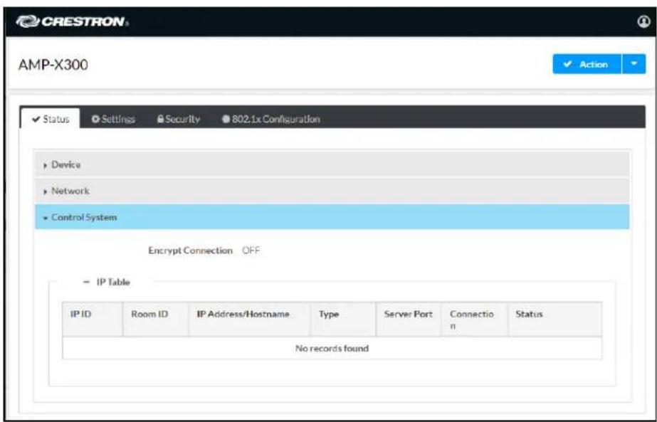
- Encrypt Connection: ON or OFF
• IP ID: Reports the currently used IP ID of the DM-NAX-AMP-X300
• IP Address/Hostname: The IP address of the control system
• Room ID: Displays the room ID - Status: OFFLINE or ONLINE
Settings
The Settings tab enables configuration of the DM-NAX-AMP-X300 settings. The Settings page can be accessed at any time by clicking the Settings tab of the DM-NAX-AMP-X300 interface.
Many options in the Settings tab are exclusive to a specific device mode: Residential or Commercial. The DM-NAX-AMP-X300 is in Commercial mode by default.
This section provides the following information:
• Commercial Mode on page 418
• Residential Mode on page 439
Commercial Mode
This section provides the following information:
• System Setup on page 419
• Commissioning on page 424
• Output Channels on page 424
• Input Channels on page 430
• DM NAX Streams on page 431
• Port Selection on page 434
- Mixing on page 435
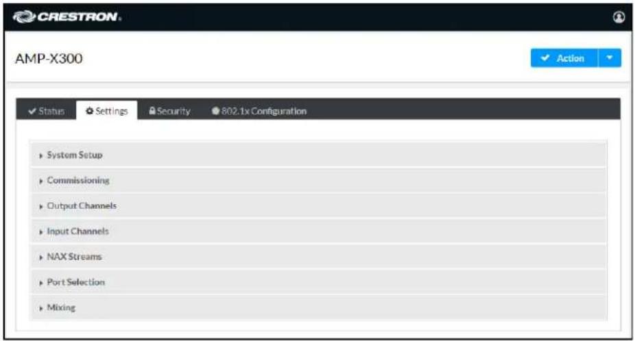
System Setup
The System Setup section contains settings for Date/Time, Auto Update, Network, Control System, Cloud Settings, and Device Modes.
Date/Time
Use the Date/Time section to configure the date and time settings of the DM-NAX-AMP-X300.
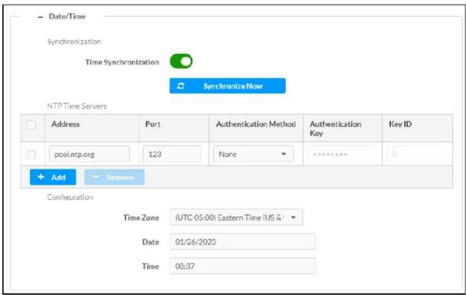
Time Synchronization
- Set the Time Synchronization toggle to the right position to enable or left position to disable time synchronization. By default, time synchronization is enabled.
- In the NTP Time Servers table, enter the URL of a NTP (Network Time Protocol) or SNTP (Simple Network Time Protocol) server. Up to three time servers can be added on a device.
- Click Synchronize Now to perform time synchronization between the device's internal clock and the time server.
Time Configuration
- Click on the Time Zone drop-down menu to select the applicable time zone.
- In the Date field, enter the current date.
- In the Time (24hr Format) field, enter the current time in 24-hour format.
Click the Save Changes button to save the settings.
Click Revert from the Actions drop-down menu to revert to the previous settings without saving.
Auto Update
The DM-NAX-AMP-X300 can automatically check for and install firmware updates at scheduled intervals via the Auto Update feature.
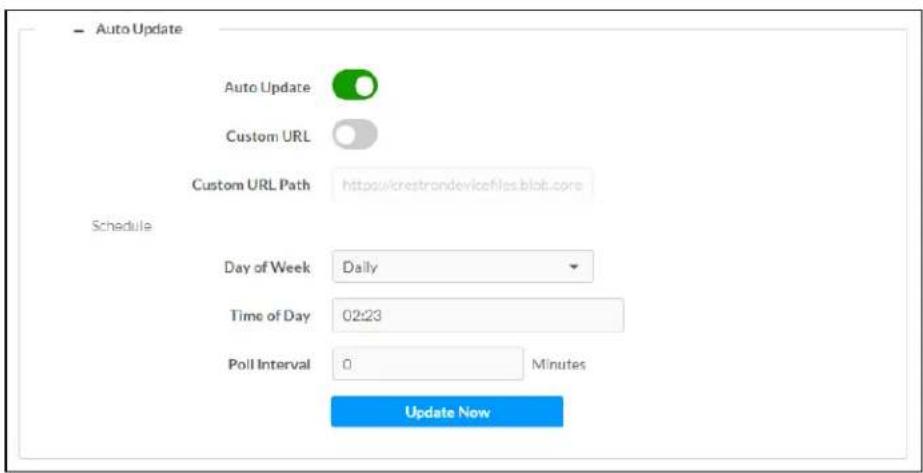
-
Set the Auto Update toggle to the right position to enable Auto Update.
-
Define the URL to download the updates by doing either of the following:
a. Use the default URL to download the updates from the Crestron server.
b. Use a custom URL. Set the Custom URL toggle to the right position to enable a custom URL. In the Custom URL Path text box, enter the path to a custom manifest file in the F or SFTP URL format. Use the Crestron Auto Update Tool to generate a custom manifest file, then store the file on an FTP (File Transfer Protocol) or SFTP (Secure File Transfer Protocol) server.
- Set a schedule for the automatic firmware update by doing either of the following:
a. Select the desired Day of Week and Time of Day (24-hour format) values.
b. Set the Poll Interval by entering a value from 60 to 65535 minutes. A value of 0 disables the Poll Interval.
- Click Save Changes.
Clicking Update Now causes the device to check for a firmware update immediately. If a schedule was set in step 4 above, that schedule still remains in effect.
Network
The Network section contains network-related settings for the DM-NAX-AMP-X300, including the Hostname, Domain, Primary Static DNS, and Secondary Static DNS.
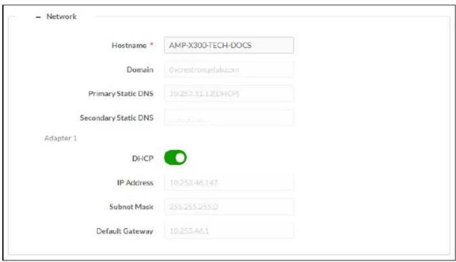
NOTE: By default, the hostname of the DM-NAX-AMP-X300 consists of the model name followed by the MAC address of the device. For example, DM-NAX-AMP-X300-00107FB58088.
Adapter 1
The Adapter 1 subheading contains settings for DHCP, IP Address, Subnet Mask, and Default Gateway of Ethernet adapter 1 on the rear panel of the device.
NOTES:
- An + Adapter 2 option only appears when the dual Ethernet ports on the DM-NAX-8ZSA are set to isolate traffic using the Port Selection feature. The settings for Adapter 2 are identical to those available for Adapter 1.
- DM NAX devices' internal processes use IP addresses in the 10x10 range. This IP range should be avoided when addressing DM NAX devices to prevent conflicts with these internal addresses.
Set the DHCP toggle to enabled (right) or disabled (left) to specify whether the IP address of the DM-NAX-AMP-X300 is to be assigned by a DHCP (Dynamic Host Configuration Protocol) server.
- Enabled: When DHCP is enabled (default setting), the IP address of the DM-NAX-AMP-X300 is automatically assigned by a DHCP server on the local area network (LAN).
- Disabled: When DHCP is disabled, manually enter information in the following fields:
Primary Static DNS: Enter a primary DNS IP address.
Secondary Static DNS: Enter a secondary DNS IP address.
- IP Address: Enter a unique IP address for the DM-NAX-8ZSA.
- Subnet Mask: Enter the subnet mask that is set on the network.
Default Gateway: Enter the IP address that is to be used as the network's gateway.
To save any new network entries, click Save Changes.
Control System

-
Click the Encrypt Connection button to navigate to the Security tab to configure encryption settings.
-
Enter a username in the Control System Username field.
-
Enter a password in the Control System Password field.
-
Enter the Room ID in the Room ID field.
-
Enter the IP ID of the DM-NAX-AMP-X300 in the IP ID field.
-
Enter the IP address or hostname of the control system in the IP Address/Hostname field.
-
Click the Save Changes button to save the new entries. The Control System Save message box appears, indicating that the control system settings were saved successfully. Click the Revert button to revert to the previous settings without saving.
Cloud Settings

Set the Cloud Settings toggle to enabled (right) or disabled (left) to specify whether the DM-NAX-AMP-X300 can communicate with the XiO Cloud® platform.
Device Modes
Use the Device Modes section to configure the Application Mode, Audio-Over-IP Mode, and Standby Mode, as well as see a live status readout of the device's rear panel functionality.

- Application Mode: The Application Mode determines which options and controls are available.
Select Residential (Standard) or Commercial (Advanced). A Reboot confirmation message box appears.

Click Yes, Reboot Now to reboot the device into the selected mode. The Reboot message box appears.
- Wait for the device reboot to complete before attempting to reconnect to the device.
- Audio Over IP Mode: Select NAX (AES67) or Dante to specify what type of audio-over-IP streams the DM-NAX-AMP-X300 will accept and transmit.
NOTE: In NAX (AES67) mode, the DM-NAX-AMP-X300 can still accept streams from Dante devices by way of the AES67 Compatibility Mode feature, which can be enabled on most Dante devices.
- Rear Panel Lockout: Set the Rear Panel Lockout toggle to specify whether the physical controls on the rear panel are locked (right) or functional (left). When locked, all device controls are handled through this menu.
- Standby Mode: Select the DM-NAX-AMP-X300's standby behavior.
-
Always On: The device's amplifier remains powered on at all times.
Power Saver: If no signal is detected for 25 minutes, the device enters a low power state by turning off the amplifier board. Upon detecting an audio signal, the amplifier will be turned back on. -
Channel 1/2 Output Drive: Set Channel 1/2 to Standard or Bridged. This option is only selectable when the Output Mode is set to Lo-Z.
- Channel 3/4 Output Drive: Set Channel 3/4 to Standard or Bridged. This option is only selectable when the Output Mode is set to Lo-Z.
-
Output Mode: The DM-NAX-AMP-X300 can be configured to work with 4 Ω and 8 Ω (low impedance or "Lo-Z") loads or a distributed audio (high impedance or "Hi-Z") 70/100V system.
-
Lo-Z: Select Lo-Z to use the amplifier with 4 Ω or 8 Ω low impedance loudspeakers.
- 70V: Select 70V to use the amplifier in a 70V distributed audio system.
- 100V: Select 100V to use the amplifier in a 100V distributed audio system.
Commissioning
The Commissioning section provides a quick way to automatically assign multicast addresses to all of the device's internal audio-over-IP stream transmitters.

Click Assign Addresses to give each DM NAX transmitter in the DM-NAX-AMP-X300 a unique multicast address beginning with the specified Starting Multicast Address. The valid range for Starting Multicast Address is 239.8.0.0 to 239.127.255.255.
NOTE: This will begin transmitting multicast traffic on your network, refer to the General Network Requirements document for details.
Output Channels
The Output Channels section enables the viewing and configuration of Zone outputs.

Zones
In the Zones section, the properties of each zone can be viewed and configured.

bar
| Name | Amp1 | Amp2 | Amp3 | Amp4 | LineOut1 | LineOut2 | LineOut3 | LineOut4 | StreamOutICp | StreamOutICr | StreamOutICr | Total | |---|---|---|---|---|---|---|---|---|---|---|---|---| | Volume (%) | 50 | 50 | 50 | 50 | 50 | 50 | 50 | 50 | 50 | 50 | 50 | 50 | | Signal Pressure | ✓ | ✓ | ✓ | ✓ | ✓ | ✓ | ✓ | ✓ | ✓ | ✓ | ✓ | ✓ | | Signal Level | ✓ (✓) | ✓ (✓) | ✓ (✓) | ✓ (✓) | ✓ (✓) | ✓ (✓) | ✓ (✓) | ✓ (✓) | ✓ (✓) | ✓ (✓) | ✓ (✓) | ✓ | | Multi | ✓ (✓) | ✓ (✓) | ✓ (✓) | ✓ (✓) | ✓ (✓) | ✓ (✓) | ✓ (✓) | ✓ (✓) | ✓ (✓) | ✓ (✓) | ✓ (✓) | ✓ | | Action | IP run | IP run | IP run | IP run | IP run | IP run | IP run | IP run | IP run | IP run | IP run | IP | The chart displays a single data series with values for each category. The Y-axis represents the percentage or count of occurrences, and the X-axis represents the categories. Values are estimated based on the 'IP run' label in the legend. The chart is saved as a PNG file named 'Zions Software'.Signal Presence indicates whether or not an audio signal is detected in that zone.
Signal Level indicates if the signal is Clipping or Nominal (non-clipping).
- Nominal: The signal level is within normal operating bounds and below the clipping threshold.
- Clipping: The signal level is clipping or above the -3 dB warning threshold and in danger of clipping.
Give each zone a friendly name using the Name row of the Zones table. If the device is paired with a control system, these names may be overwritten by the control system's program.
To configure the zone volume, do one of the following:
- Move the Volume slider up to increase or down to decrease the zone volume.
- Click the % arrows to increase or decrease the zone volume. Values range from 0 to 100%, adjustable in increments of 1%.
- Manually enter a value in the Volume field.
To mute all audio output from a zone, click its respective Mute button. To unmute the zone, click the Muted button.
Click Edit to view additional Zone and Output options.
Zone
To configure additional zone settings, click the Edit button. The Edit Zone window appears.
Click Zone to access the settings for Tone and Delay.

Tone
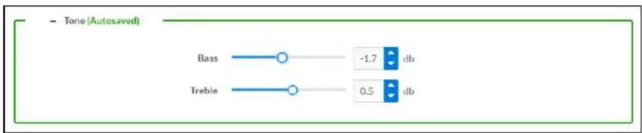
- Bass: To adjust the bass, do one of the following:
- Move the Bass slider to the right to increase or to the left to decrease the bass db.
- Click the db arrows to increase or decrease the db. Values range from -12 db to 12 db, adjustable in increments of .1 db.
- Manually enter a value in the Bass field.
- Treble: To adjust the treble, do one of the following:
- Move the Treble slider to the right to increase or to the left to decrease the treble db.
- Click the db arrows to increase or decrease the db. Values range from -12 db to 12 db, adjustable in increments of .1 db.
- Manually enter a value in the Treble field.
Delay

To set the delay, do one of the following:
- Move the Delay Time(ms) slider to the right to increase or to the left to decrease the delay time.
- Click the ms arrows to increase or decrease the delay. Values range from 0 ms to 250 ms, adjustable in increments of 1 ms.
- Manually enter a value in the Delay Time(ms) field.
Output
Click Output to access the settings for Minimum/Maximum, Signal, Speaker Configuration, Speaker/Faults, and Equalizer Settings.
Minimum/Maximum Volume
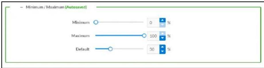
bar
| Category | Value | Percentage | | ---------- | ----- | ---------- | | Minimum | 0 | % | | Maximum | 100 | % | | Default | 30 | % |-
To set the minimum volume of the zone, do one of the following:
-
Move the Minimum slider to the right to increase or to the left to decrease the minimum volume.
- Click the % arrows to increase or decrease the minimum volume. Values range from 0 to 50%, adjustable in increments of 1%.
-
Manually enter a value in the Minimum field.
-
To set the maximum volume of the zone, do one of the following:
-
Move the Maximum slider to the right to increase or to the left to decrease the maximum volume.
- Click the % arrows to increase or decrease the maximum volume. Values range from 70 to 100%, adjustable in increments of 1%.
- Manually enter a value in the Maximum field.
NOTE: When a Minimum and Maximum volume are set, the 1-100% range represented by the Zone and Default volume controls are scaled to the range set. For example, if a Minimum of 10% and a Maximum of 80% are set for a zone, the 1-100% range of the Zone volume control is scaled to the 10%-80% range set as the Minimum and Maximum.
-
To set the default volume of the zone, do one of the following:
-
Move the Default slider to the right to increase or to the left to decrease the default volume.
- Click the % arrows to increase or decrease the default volume. Values range from 0 to 50% adjustable in increments of 1%.
- Manually enter a value in the Default field.
NOTE: The Default volume is applied as the Zone volume any time the zone receives a source route and no source was previously routed to that zone.
Signal

The Signal section is a read-only field that displays the Signal and Clipping status of the zone output.
- If an output signal is present but not clipping, Signal will display Present in green and Clipping will display None in green.
- If an output signal is present and clipping, Signal will display Present in green and Clipping will display Present in red.
- If no output signal is detected, Signal will display Not Present in red and Clipping will display None in green.
Speaker Configuration
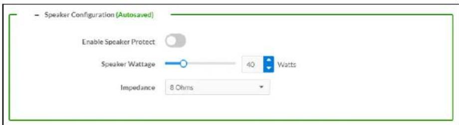
-
Set the Enable Speaker Protect toggle to the right position to enable speaker protection for the zone output. Set the toggle to the left position to disable speaker protection. By default, Enable Speaker Protect is set to the left position.
-
To set the maximum output wattage, do one of the following:
-
Move the Speaker Wattage slider to the right to increase or to the left to decrease the maximum peak amplifier wattage that can be output to the speaker.
- Click the Watts arrows to increase or decrease the maximum peak amplifier wattage that can be output to the speaker. Values range from 5 W to 150 W, adjustable in increments of 1 W.
-
Manually enter a value in the Speaker Wattage field.
-
Select the impedance of the speaker on a selected zone from the Impedance drop-down menu. Values are 4 Ohms, 8 Ohms, and Bridged.
Speaker Faults
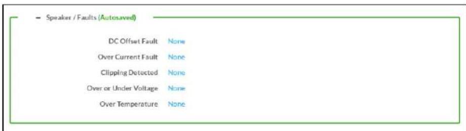
The Speaker/Faults section is a read-only field that displays the status of the DC Offset Fault, Over Current Fault, Clipping Detected, Over or Under Voltage, and Over Temperature detectors for the zone output. If clipping or a given fault type is detected, then its corresponding readout displays Fault Detected in red. Otherwise, it displays None in blue.
Equalizer Settings
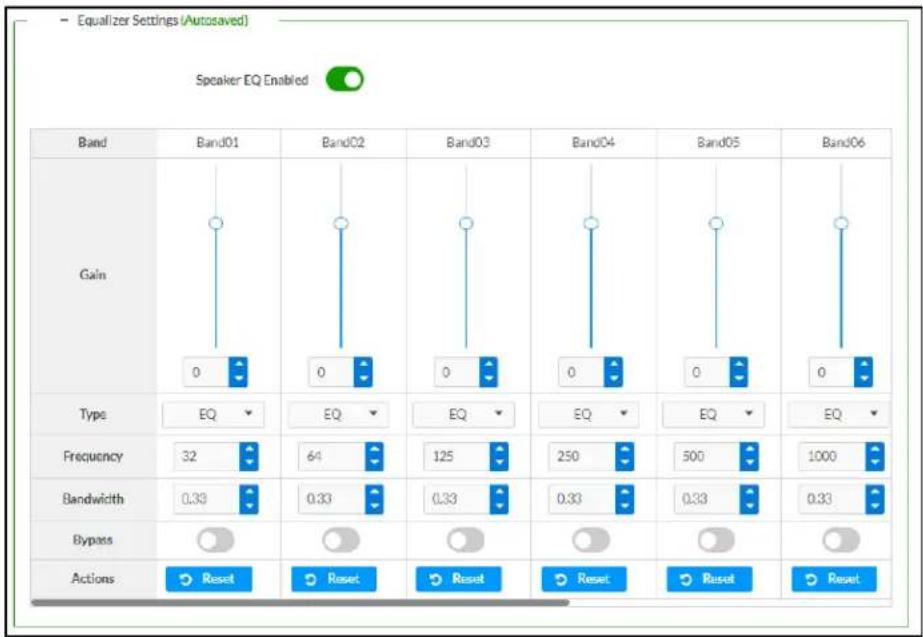
Each zone output of the DM-NAX-AMP-X300 has a dedicated ten-band equalizer that can be fully customized to tune the zone output signal to the needs of an install. Each band can have a discrete ga filter type, center frequency, and bandwidth set, and can also be bypassed. The equalizer itself can also be bypassed using the Speaker EQ Enabled toggle.
- Set the Speaker EQ Enabled toggle to the right position to enable the equalizer. Set the toggle to the left position to bypass the equalizer.
NOTE: When Speaker EQ Enabled is disabled, all equalizer bands are bypassed. This is a quick way to perform A/B testing of the entire EQ curve.
- With the Speaker EQ Enabled toggle in the right position, do the following to configure a given equalizer band:
a. To set a band's gain, do one of the following:
- Move the Gain slider up to increase or down to decrease the gain.
- Click the arrows to increase or decrease the gain. Values range from -40 dB to 20 dB, adjustable in increments of 0.1 dB.
- Manually enter a value in the Gain field.
b. Select a filter type from the Type drop-down menu. By default, all bands are set to the EQ filter type. Some filter types will disable other settings in their respective band while enabled. For example, selecting the LowPass filter type for a band will disable that band's Gain and Bandwidth settings, since the LowPass filter applies a fixed roll-off slope at a set frequency. The available filter types are:
- EQ: a fully parametric filter that can boost or cut a range of frequencies.
- Notch: a parametric filter designed to more precisely cut a frequency or range of frequencies. A notch filter can achieve a narrower bandwidth than the standard EQ parametric filter type.
- TrebleShelf: a filter that boosts or cuts all frequencies above a set frequency by a set gain.
- BassShelf: a filter that boosts or cuts all frequencies below a set frequency by a set gain.
- LowPass: a filter that fully cuts all frequencies above a set frequency using a fixed roll-off slope of -12 dB per octave.
- HighPass: a filter that fully cuts all frequencies below a set frequency using a fixed roll-off slope of -12 dB per octave.
c. Set a center frequency for the equalizer band to tune a specific portion of the audible frequency spectrum. To set the center frequency, do one of the following:
- Click the arrows to increase or decrease the frequency. Values range from 20 Hz to 20 kHz, adjustable in increments of 1 Hz. Each band has a default center frequency that will be applied if the Reset button at the bottom of the band is clicked.
- Manually enter a value in the Frequency field.
d. Set a bandwidth to determine how wide of a frequency range is effected by the equalizer band. To set the bandwidth, do one of the following:
- Click the arrows to increase or decrease the bandwidth. Values range from 0.1 octaves to 4.0 octaves, adjustable in increments of 0.1 octave.
- Manually enter a value in the Bandwidth field.
e. The individual Bypass controls allow you to bypass a single band of equalization at a time for more granular A/B testing of a single filter. Set a band's Bypass toggle to the right position to bypass that band. Set the toggle to the left position to disable the bypass. By default, Bypass is disabled.
f. Each equalizer band has a Reset button that will reapply the default settings for that band.
Click Done to return to the Settings tab of the web user interface.
Input Channels
The Input Channels section enables the viewing and configuration of Analog Inputs.
- Input Channels

Signal Presence indicates whether or not a signal is detected in that zone.
Signal Level indicates if the signal is Clipping or Nominal (non-clipping).
-
If needed, enter a friendly name for each input in its Name field.
• To set a level compensation adjustment for a given input, do one of the following: -
Slide the Compensation slider up to increase or down to decrease the compensation. Compensation increases the level of the incoming audio signal on any of the physical inputs on the device's rear panel.
- Click the db arrows to increase or decrease the compensation. Values range from -10 db to 10 db, adjustable in increments of .1 db.
-
Manually enter a value in the Compensation field.
-
Use the Mode drop-down to select Line or Mic.
- If using Mic Mode, Phantom Power can be enabled by moving the Phantom Power toggle to the right. Disable Phantom Power by moving the toggle to the left.
- To mute the signal from the corresponding input, click the Mute button. To disable the mute, click the Muted button. By default, Mute is disabled.
DM NAX Streams
Each local input of the DM-NAX-AMP-X300 can be made available as a DM NAX audio-over-IP stream.
The DM-NAX-AMP-X300 also supports parallel DM NAX streams for each zone output, enabling an additional transmit stream per output to mirror all routes and DSP settings of its respective zone. These parallel streams enable control of the audio signal to third-party uncontrolled AES67 devices receiving audio from the DM-NAX-AMP-X300.
NOTES:
- Under the Transmitters section (see Configure Transmitters), the last two listed transmitters are dedicated to parallel zone outputs.
• To configure the DSP settings, see Zone Settings.
Click NAX Streams to display the following information.

- Device is Master PTP Clock Source indicates whether the device is the master for PTP on the network. Yes will be displayed in green when the local DM-NAX-AMP-X300 is the PTP clock master and No will be displayed in red when another PTP clock on the network is operating as the master clock.
- Master Clock Status displays the Master Clock ID of the device on the network that acts as the Master Clock.
- PTP Priority: This sets the priority of the local DM NAX device's PTP clock relative to other clocks on the network. The default setting is 254 (one increment higher than the lowest possible value) so that the DM-NAX-AMP-X300 will only operate as clock master if no other PTP master is present on the network. Valid values range from 1 to 255.
Configure Transmitters

To configure a DM NAX transmit stream, do the following.
- Enter a valid multicast address in the NAX Stream Address field.
-
Enter a name in the NAX Stream Name field by which the stream can be identified. This stream name is associated with the DM NAX stream's multicast address by other DM NAX or AES67 devices, like a device hostname that resolves to a given IP address.
-
Status indicates whether a stream is transmitting or not. When the stream has started or stopped, the Status column will update accordingly.
-
Click the configure button (💡) in the Actions column. The Configure dialog appears:

-
Set the Auto Initiation toggle to the right position to enable auto initiation. Set the toggle to the left position to disable auto initiation.
-
If Auto Initiation is enabled for a given stream, the stream will begin transmitting automatically and will be available as a multicast stream on your network at the specified multicast address.
-
If Auto Initiation is disabled for the input, the stream will not begin transmitting until it is manually initiated.
-
To set the port number, do one of the following:
-
Click the arrows to increase or decrease the port number by increments of 1.
-
Manually enter a port number in the Port field. The default port number for DM NAX streams is 5004.
-
Click OK to save or click Cancel to cancel the changes.
Configure Receivers

- Enter the multicast address of a transmitting stream in the Requested Stream Address field to subscribe the receiver to the stream.
- Click the configure button (💡) in the Actions column. The Configure dialog appears:

-
Set the Auto Initiation toggle to the right position to enable auto initiation. Set the toggle to the left position to disable auto initiation.
-
If Auto Initiation is enabled, the stream will begin automatically when the receiver subscribes to the transmitter.
• If Auto Initiation is disabled, the stream will not begin until it is manually initiated. -
To set the port number, do one of the following:
-
Click the arrows to increase or decrease the port number by increments of 1.
• Manually enter a port number in the Port field. The default port number is 5004. -
Click OK to save or click Cancel to cancel the changes.
Port Selection
The Port Selection feature allows the device's internal network traffic to be managed and segregated based on traffic type. Internal VLANs are used to segment device management and streaming service traffic to a separate physical device Ethernet port than audio-over-IP streaming traffic. With Port Selection enabled on all DM NAX devices on a network, DM NAX and AES67 network traffic can be physically separated from the control network onto a dedicated audio network.

To configure Port Selection:
- Set the Port Selection toggle to the right position to enable Port Selection. Set the toggle to the left position to disable Port Selection. By default, Port Selection is disabled.
NOTE: Ports 1 and 2 correspond to the Ethernet adapters labeled 1 and 2 on the rear panel of the DM-NAX-AMP-X300, respectively.
- With Port Selection enabled, select an Ethernet port from the Management drop-down menu to designate which Ethernet port on the rear panel of the device will handle network traffic relating to device configuration and the device's connection to a control system.
NOTE: The Management port determines your connection to the web interface. Changing the port value can result in losing your connection to the device via the web interface.
-
With Port Selection enabled, select an Ethernet port from the Audio/NAX drop-down menu to designate which Ethernet port on the rear panel of the device will handle audio-over-IP streaming network traffic.
-
Click Save changes to apply the new settings.
NOTE: Making changes to Port Selection settings will require a reboot.
Mixing
This section contains the Mixing and Ducking matrices.

Mixing
The Mixing matrix is used to route a local input or AES67 stream to an output on the DM-NAX-AMP-X300.
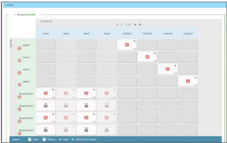
To route inputs to outputs on the device:
- Click the cells corresponding to the desired output that are to be paired for routing. Once a route is made, appears. The input that you have selected for a given row will route to the output corresponding to that row in the matrix.
- Use the arrows (or) at the top of the matrix to change pages to view all available inputs.
• To break a given route click or - Lock icons appear on any routes that are already configured in the Ducking matrix.
Each output can have any number of inputs routed to it. To adjust the mix setting for a route, click the dB value of the cell, then do one of the following:
- Move the slider up to increase or down to decrease the mix level.
- Click the arrows to increase or decrease the mix level.
- Manually enter a value in the field.

Ducking
The Ducking matrix is used to configure ducking routes. Audio signals on these routes will duck audio signals on the Mixing routes for a given output whenever the ducking signal exceeds the ducking threshold.

To assign inputs as ducking signals for zones on the device:
- Click the cells corresponding to the desired zone that are to be paired for ducking. Once a route is made, appears. The input that you have selected for a given row will route to the zone corresponding to that row in the matrix, and will duck any other signals routed to that zone in the Mixing matrix.
- Use the arrows (or) at the top of the matrix to change pages to view all available inputs.
• To break a given route click or
- Lock icons appear on any routes that are already configured in the Mixing matrix.
Each output can have any number of inputs routed to it. To adjust the mix setting for a route, click the dB value of the cell, then do one of the following:
- Move the slider up to increase or down to decrease the mix level.
- Click the arrows to increase or decrease the mix level.
• Manually enter a value in the field.

To configure the Ducker settings for a given output, select the configure button ( ) below it.

Logic Out: This indicator turns blue when the ducker is active.
Bypass: Set the Bypass toggle to the right position to bypass the ducker. Set the toggle to the left to enable the ducker.
Threshold: Set the dB value at which the ducker engages. Use the arrows or enter a number to set the dB value for the Threshold. Values range from 0 dB to -60 dB.
Attenuation: Set the dB value by which the Mixing matrix output signals will be reduced when ducking is triggered. Use the arrows or enter a number to set the dB value for the Attenuation. Values range from 0 dB to -80 dB.
Attack: Set how quickly the ducking occurs once triggered. Use the arrows or enter a number to set value in ms for the Attack. Values range from 0.1 ms to 2000 ms.
Hold: Set the length of time for which the ducker will stay at full attenuation once the ducking signal passes the Threshold. Use the arrows or enter a number to set a value in seconds for the Hold. Values range from 0.1s to 20s.
Release: Set the time for the Mixing matrix output signal to return to its full level after the ducking signal falls below the threshold and the Hold time ends. Use the arrows or enter a number to set the value in ms for the Release. Values range from 10 ms to 4000 ms.
Residential Mode
This section provides the following information:
• System Setup on page 440
• Commissioning on page 444
- Zones on page 445
• Bussing on page 457
- Inputs on page 458
• NAX Streams on page 458
- Routing on page 461
• Port Selection on page 461

System Setup
The System Setup section displays information about the Date/Time, Auto Update, Network, Control System, Cloud Settings, and Device Modes.
Date/Time
Use the Date/Time section to configure the date and time settings of the DM-NAX-AMP-X300.
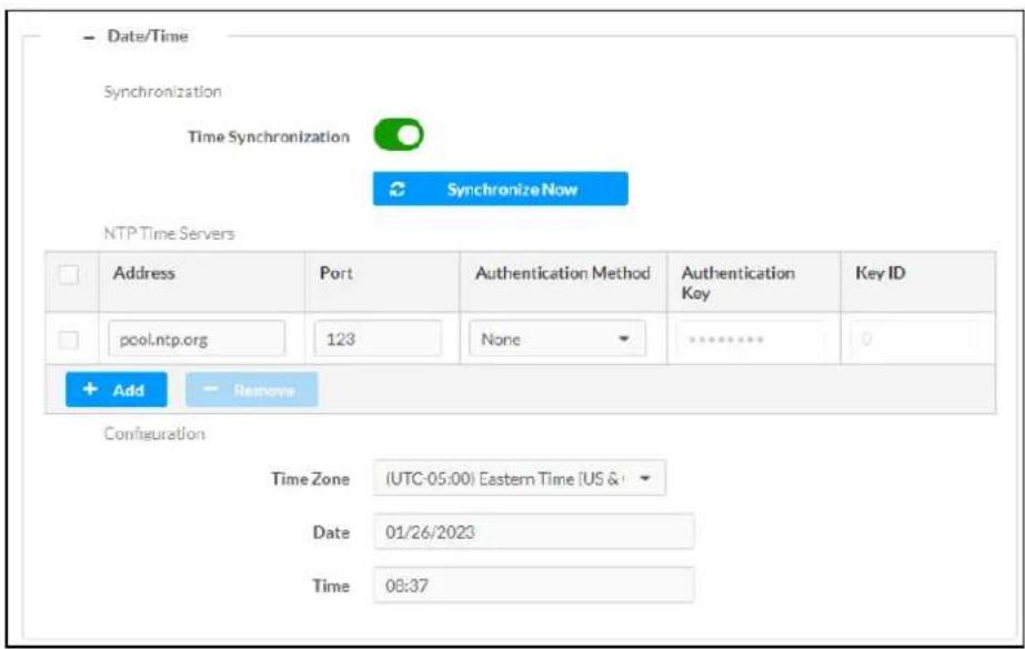
Time Synchronization
- Set the Time Synchronization toggle to the right position to enable or left position to disable time synchronization. By default, time synchronization is enabled.
- In the NTP Time Servers table, enter the URL of a NTP (Network Time Protocol) or SNTP (Simple Network Time Protocol) server. Up to three time servers can be added on a device.
- Click Synchronize Now to perform time synchronization between the device's internal clock and the time server.
Time Configuration
- Click on the Time Zone drop-down menu to select the applicable time zone.
- In the Date field, enter the current date.
- In the Time (24hr Format) field, enter the current time in 24-hour format.
Click the Save Changes button to save the settings.
Click Revert from the Actions drop-down menu to revert to the previous settings without saving.
Auto Update
The DM-NAX-AMP-X300 can automatically check for and install firmware updates at scheduled intervals via the Auto Update feature.
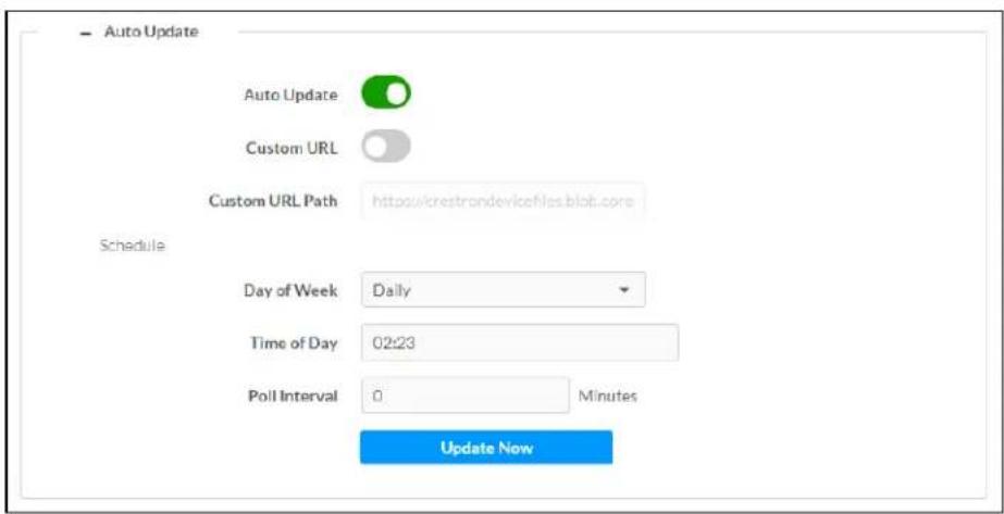
-
Set the Auto Update toggle to the right position to enable Auto Update.
-
Define the URL to download the updates by doing either of the following:
a. Use the default URL to download the updates from the Crestron server.
b. Use a custom URL. Set the Custom URL toggle to the right position to enable a custom URL. In the Custom URL Path text box, enter the path to a custom manifest file in the F or SFTP URL format. Use the Crestron Auto Update Tool to generate a custom manifest file, then store the file on an FTP (File Transfer Protocol) or SFTP (Secure File Transfer Protocol) server.
- Set a schedule for the automatic firmware update by doing either of the following:
a. Select the desired Day of Week and Time of Day (24-hour format) values.
b. Set the Poll Interval by entering a value from 60 to 65535 minutes. A value of 0 disables the Poll Interval.
- Click Save Changes.
Clicking Update Now causes the device to check for a firmware update immediately. If a schedule was set in step 4 above, that schedule still remains in effect.
Network
The Network section contains network-related settings for the DM-NAX-AMP-X300, including the Hostname, Domain, Primary Static DNS, and Secondary Static DNS.
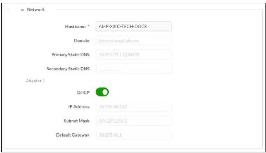
NOTE: By default, the host name of the DM-NAX-AMP-X300 consists of the model name followed by the MAC address of the device. For example, DM-NAX-AMP-X300-00107FB58088.
Adapter 1
The Adapter 1 subheading contains settings for DHCP, IP Address, Subnet Mask, and Default Gateway of Ethernet adapter 1 on the rear panel of the device.
NOTES:
- An + Adapter 2 option only appears when the dual Ethernet ports on the DM-NAX-AMP-X300 are set to isolate traffic using the Port Selection feature. The settings for Adapter 2 are identical to those available for Adapter 1.
- DM NAX devices' internal processes use IP addresses in the 10x10.16nge. This IP range should be avoided when addressing DM NAX devices to prevent conflicts.
Set the DHCP toggle to enabled (right) or disabled (left) to specify whether the IP address of the DM-NAX-AMP-X300 is to be assigned by a DHCP (Dynamic Host Configuration Protocol) server.
- Enabled: When DHCP is enabled (default setting), the IP address of the DM-NAX-AMP-X300 is automatically assigned by a DHCP server on the local area network (LAN).
-
Disabled: When DHCP is disabled, manually enter information in the following fields:
-
Primary Static DNS: Enter a primary DNS IP address.
Secondary Static DNS: Enter a secondary DNS IP address.
IP Address: Enter a unique IP address for the DM-NAX-AMP-X300. - Subnet Mask: Enter the subnet mask that is set on the network.
Default Gateway: Enter the IP address that is to be used as the network's gateway.
To save any new network entries, click Save Changes.
Control System
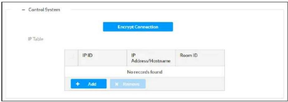
- Click the Encrypt Connection button to navigate to the Security tab to configure encryption settings.
- Enter the username in the Control System Username field.
- Enter the password in the Control System Password field.
- Enter the Room ID in the Room ID field.
- Enter the IP ID of the DM-NAX-AMP-X300 in the IP ID field.
- Enter the IP address or hostname of the control system in the IP Address/Hostname field.
- Click the Save Changes button to save the new entries. The Control System Save message box appears, indicating that the control system settings were saved successfully. Click the Revert button to revert to the previous settings without saving.
Cloud Settings

Set the Cloud Settings toggle to enabled (right) or disabled (left) to specify whether the DM-NAX-AMP-X300 can communicate with the XiO Cloud® platform.
Device Modes
Use the Device Modes section to configure the Application Mode and Standby Mode.

- Application Mode: The Application Mode determines which options and controls are available.
Select Residential (Standard) or Commercial (Advanced). A Reboot confirmation message box appears.

- Click Yes, Reboot Now to reboot the device into the selected mode. The Reboot message box appears.
- Wait for the device reboot to complete before attempting to reconnect to the device.
- Standby Mode: Select the DM-NAX-AMP-X300's standby behavior.
° Always On: The device's amplifier remains powered on at all times.
Power Saver: If no signal is detected for 25 minutes, the device enters a low power state by turning off the amplifier board. Upon detecting an audio signal, the amplifier will be turned back on.
Commissioning
The Commissioning section provides a quick way to automatically assign multicast addresses to all of the device's internal audio-over-IP stream transmitters.
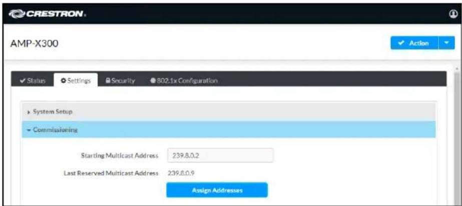
Click Assign Addresses to give each DM NAX transmitter in the DM-NAX-AMP-X300 a unique multicast address beginning with the specified Starting Multicast Address. The valid range for Starting Multicast Address is 239.8.0.0 to 239.127.255.255.
NOTE: This will begin transmitting multicast traffic on your network, refer to the General Network Requirements document for details.
Zones
The Zones section contains the Volume and Mute settings for all zone outputs of the device, as well as a Configure option for more advanced settings within each zone.

Give each zone a friendly name using the Name column of the Zones table. If the device is paired with a control system, these names may be overwritten by the control system's program.
To configure the zone volume, do one of the following:
- Move the Volume slider to the right to increase or to the left to decrease the zone volume.
- Click the % arrows to increase or decrease the zone volume. Values range from 0 to 100%, adjustable in increments of 1%.
- Manually enter a value in the Volume field.
To mute all audio output from a zone, click its respective Mute button. To unmute the zone, click the Muted button.
Zone Settings
To configure zone settings, click the Configure button (Configure). The Edit Zone window appears.
Zone
Click Zone to access the settings for Tone, Balance, and Delay.

Tone
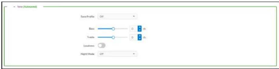
The Tone section provides adjustments for the Tone Profile, Bass, Treble, Loudness, and Night Mode settings of the zone output.
NOTE: The Tone Profile, Bass, Treble, and Loudness settings in the Tone section are all applied separately from the Equalizer Settings for the zone. This means that any adjustments made in the Tone section will stack with those made in the Equalizer Settings section.
-
To select a tone profile preset for the zone, select an option from the Tone Profile drop-down menu. The available options are Off, Classical, Jazz, Pop, Rock, and Spoken Word. By default, Off is selected.
-
Bass: To adjust the bass, do one of the following:
-
Move the Bass slider to the right to increase or to the left to decrease the bass.
- Click the db arrows to increase or decrease the db. Values range from -12 db to 12 db, adjustable in increments of 1 db.
-
Manually enter a value in the Bass field.
-
Treble: To adjust the treble, do one of the following:
-
Move the Treble slider to the right to increase or to the left to decrease the treble.
- Click the db arrows to increase or decrease the db. Values range from -12 db to 12 db, adjustable in increments of 1 db.
-
Manually enter a value in the Treble field.
-
To enable the loudness setting on the zone output, slide the Loudness switch to the right. To disable loudness, slide the Loudness switch to the left.
-
The Night Mode feature applies subtle processing to restrict the dynamic range of the zone audio, to allow for lower listening levels at night or in rooms where higher listening levels would be disruptive. To select a dynamics processing level, select an option from the Night Mode drop-down menu. The available options are Off, Low, Medium, and High. By default, Off is selected.
Balance

To adjust the left/right balance of the stereo output signal, do one of the following:
- Move the Balance slider to the right to shift the stereo balance to the right channel or to the left to shift the balance to the left.
- Click the arrows to adjust the balance left or right. The up arrow shifts the balance to the right while the down arrow shifts the balance to the left.
- Manually enter a value in the Balance field. Values range from -50 to 50, adjustable in increments of 1. Positive values shift the balance to the right while negative values shift the balance to the left.
Delay

To set the delay, do one of the following:
- Move the Delay Time(ms) slider to the right to increase or to the left to decrease the delay time.
- Click the ms arrows to increase or decrease the delay. Values range from 0 ms to 250 ms, adjustable in increments of 1 ms.
- Manually enter a value in the Delay Time(ms) field.
Output
Click Output to access the settings for Minimum/Maximum Volume, Stereo/Mono, Signal, Bussing Volume Offset, Speaker Configuration, Speaker/Faults, Line Out, Signal Generator, and Equalizer Settings.
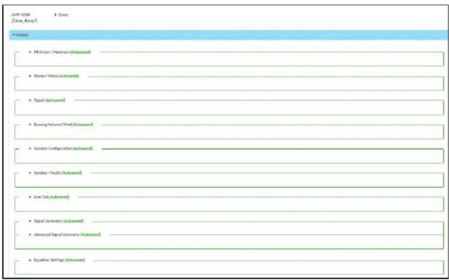
Minimum/Maximum Volume
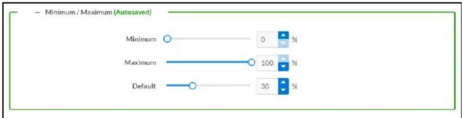
-
To set the minimum volume of the zone, do one of the following:
-
Move the Minimum slider to the right to increase or to the left to decrease the minimum volume.
- Click the % arrows to increase or decrease the minimum volume. Values range from 0 to 50%, adjustable in increments of 1%.
-
Manually enter a value in the Minimum field.
-
To set the maximum volume of the zone, do one of the following:
-
Move the Maximum slider to the right to increase or to the left to decrease the maximum volume.
- Click the % arrows to increase or decrease the maximum volume. Values range from 70 to 100%, adjustable in increments of 1%.
- Manually enter a value in the Maximum field.
NOTE: When a Minimum and Maximum volume are set, the 1-100% range represented by the Zone and Default volume controls are scaled to the range set. For example, if a Minimum of 10% and a Maximum of 80% are set for a zone, the 1-100% range of the Zone volume control is scaled to the 10%-80% range set as the Minimum and Maximum.
- To set the default volume of the zone, do one of the following:
- Move the Default slider to the right to increase or to the left to decrease the default volume.
- Click the % arrows to increase or decrease the default volume. Values range from 0 to 50% adjustable in increments of 1%.
- Manually enter a value in the Default field.
NOTE: The Default volume is applied as the Zone volume any time the zone receives a source route and no source was previously routed to that zone.
Stereo/Mono

-
Select either Stereo or Mono from the Stereo/Mono radio buttons.
-
Select the zone configuration from the Zone Configuration drop-down menu. The available values are Standard, Bridged, Bridged Sub 2.1, and Bridged Mono. See the diagrams below for the output signal flow applied in each configuration.
NOTE: The Stereo/Mono field is disabled for the Bridge Mono, and Bridged Sub 2.1 zone configurations.
Stereo - Standard

flowchart
graph LR
    A["Input"] --> B["DAC"]
    B --> C["AMP"]
    C --> D["Left Speaker"]
    C --> E["Right Speaker"]
    F["Input"] --> G["DAC"]
    G --> H["AMP"]
    H --> I["Left Speaker"]
    H --> J["Right Speaker"]
Stereo - Bridged

flowchart
graph TD
    A["Input"] --> B["BRIDGED Block 1"]
    A --> C["BRIDGED Block 2"]
    B --> D["DAC"]
    B --> E["AMP"]
    C --> F["DAC"]
    C --> G["AMP"]
    D --> H["Speaker"]
    E --> I["Speaker"]
    F --> J["Speaker"]
    G --> K["Speaker"]
    L["Left"] --> M["Speaker"]
    N["Right"] --> O["Speaker"]
Mono - Standard
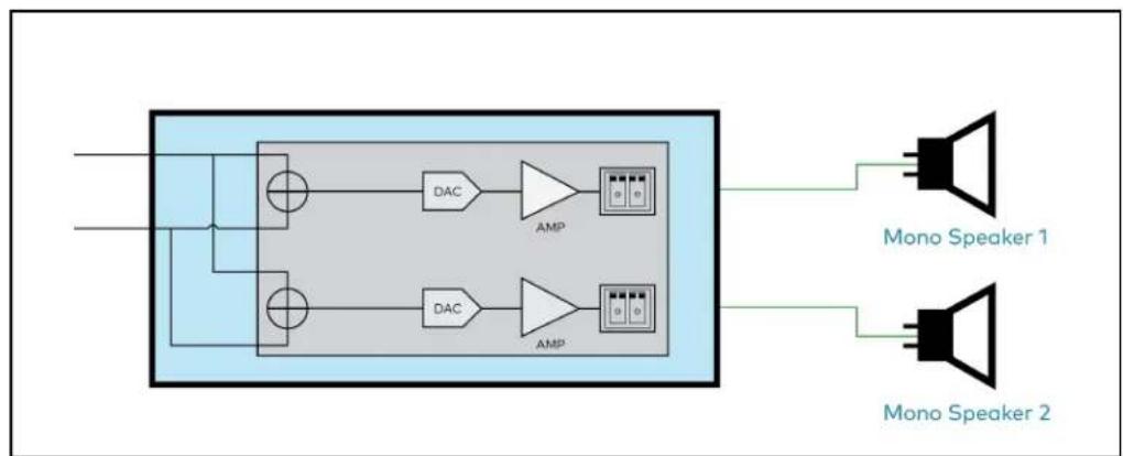
flowchart
graph TD
    A["Input"] --> B["Block"]
    B --> C["DAC"]
    B --> D["DAC"]
    C --> E["AMP"]
    D --> F["AMP"]
    E --> G["Mono Speaker 1"]
    F --> H["Mono Speaker 2"]
Mono - Bridged

flowchart
graph TD
    subgraph_BRIGDED_1["BRIDGED"]
        A1["DAC"] --> B1["AMP"]
        A2["DAC"] --> B2["AMP"]
    end
    subgraph_BRIGDED_2["BRIDGED"]
        A3["DAC"] --> B3["AMP"]
        A4["DAC"] --> B4["AMP"]
    end
    B1 --> C1["Mono Speaker 1"]
    B2 --> C2["Mono Speaker 1"]
    B3 --> C3["Mono Speaker 2"]
    B4 --> C4["Mono Speaker 2"]
Bridged Sub 2.1
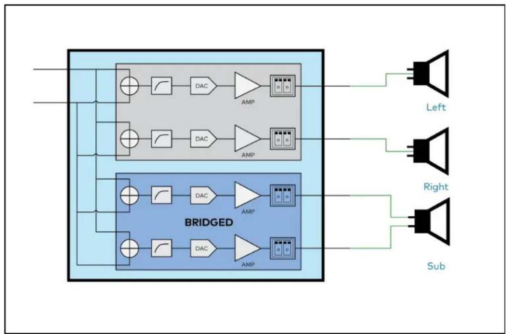
flowchart
graph TD
    subgraph_BRI_DGD["BRIDGED"]
        direction TB
        A1["○"] --> B1["DAC"]
        A2["○"] --> B2["DAC"]
        A3["○"] --> B3["DAC"]
        A4["○"] --> B4["DAC"]
        B1 --> C1["AMP"]
        B2 --> C2["AMP"]
        B3 --> C3["AMP"]
        B4 --> C4["AMP"]
    end
    subgraph BRI_DGD_BRDGED
        direction TB
        A5["○"] --> B5["DAC"]
        A6["○"] --> B6["DAC"]
        A7["○"] --> B7["DAC"]
        A8["○"] --> B8["DAC"]
        B5 --> C5["AMP"]
        B6 --> C6["AMP"]
        B7 --> C7["AMP"]
    end
    subgraph BRI_DGD_Sub
        direction TB
        A9["●"] --> B10["●"]
        A10["●"] --> B11["●"]
        A11["●"] --> B12["●"]
        A12["●"] --> B13["●"]
        A13["●"] --> B14["●"]
        A14["●"] --> B15["●"]
        A15["●"] --> B16["●"]
        A16["●"] --> B17["●"]
        A17["●"] --> B18["●"]
        A18["●"] --> B19["●"]
        A19["●"] --> B20["●"]
        A20["●"] --> B21["●"]
        A21["●"] --> B22["●"]
        A22["●"] --> B23["●"]
        A23["●"] --> B24["●"]
        A24["●"] --> B25["●"]
        A25["●"] --> B26["●"]
        A26["●"] --> B27["●"]
        A27["●"] --> B28["●"]
        A28["●"] --> B29["●"]
    end
    subgraph Left
        direction TB
        A9
        A10
        A11
        A12
        A13
        A14
        A15
        A16
        A17
        A18
        A19
    end
    subgraph Right
        direction TB
        A9
        A10
        A11
        A12
        A13
        A14
        A15
        A16
        A17
        A18
        A19
    end
    subgraph Sub
        direction TB
        A9
        A10
        A11
        A12
        A13
        A14
        A15
        A16
        A17
        A18
    end
Bridged Mono
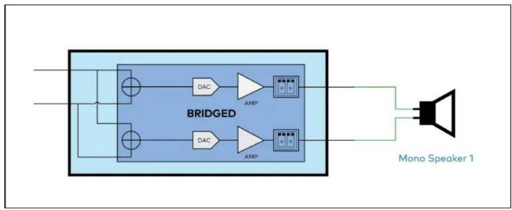
flowchart
graph LR
    A["Input"] --> B["BRIDGED"]
    B --> C["DAC"]
    B --> D["AMP"]
    B --> E["DAC"]
    B --> F["AMP"]
    C --> G["Output"]
    D --> G
    E --> G
    F --> G
    G --> H["Mono Speaker 1"]
Signal

The Signal section is a read-only field that displays the Signal and Clipping status of the zone output.
- If an output signal is present but not clipping, Signal will display Present in green and Clipping will display None in green.
- If an output signal is present and clipping, Signal will display Present in green and Clipping will display Present in red.
- If no output signal is detected, Signal will display Not Present in red and Clipping will display None in green.
Bussing Volume Offset

Bussing Volume Offset is an additional level compensation applied to the zone relative to any other zones it is grouped with via the Bussing feature.
To set the bussing volume offset, do one of the following:
- Move the Bussing Volume Offset slider to the right to increase or to the left to decrease the offset.
- Click the db arrows to increase or decrease the offset. Values range from -12 dB to 12 dB, adjustable in increments of 1 dB.
- Manually enter a value in the Bussing Volume Offset field.
Speaker Configuration
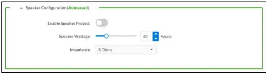
-
Set the Enable Speaker Protect toggle to the right position to enable speaker protection for the zone output. Set the toggle to the left position to disable speaker protection. By default, Enable Speaker Protect is set to the left position.
-
To set the maximum output wattage, do one of the following:
-
Move the Speaker Wattage slider to the right to increase or to the left to decrease the maximum peak amplifier wattage that can be output to the speaker.
- Click the Watts arrows to increase or decrease the maximum peak amplifier wattage that can be output to the speaker. Values range from 5 W to 150 W, adjustable in increments of 1 W.
-
Manually enter a value in the Speaker Wattage field.
-
Select the impedance of the speaker on a selected zone from the Impedance drop-down menu. Values are 4 Ohms, 8 Ohms, and Bridged.
Speaker/Faults
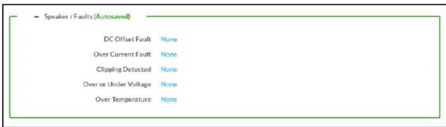
The Speaker/Faults section is a read-only field that displays the status of the DC Offset Fault, Over Current Fault, Clipping Detected, Over or Under Voltage, and Over Temperature detectors for the zone output. If clipping or a given fault type is detected, then its corresponding readout displays Fault Detected in red. Otherwise, it displays None in blue.
Line Out

Line Out Volume controls the volume level of the corresponding line-level output on the DM NAX device. The Line Out Volume is only applied when Line Out EQ Bypass is enabled.
-
To set the line out volume, do one of the following:
-
Move the Line Out Volume slider to the right to increase or to the left to decrease the line out volume.
- Click the arrows to increase or decrease the line out volume. Values range from 0 to 100, adjustable in increments of 1. This range in dB is -80 dB to 20 dB.
-
Manually enter a value in the Line Out Volume field.
-
Set the Line Out EQ Bypass toggle to the right position to have the line-level output signal bypass the zone's equalizer settings. Set the toggle to the left position to have the line-level output signal pass through the zone's equalizer. By default, Line Out EQ Bypass is disabled.
NOTE: When the Line Out EQ Bypass setting is disabled, the line-level output's level will mirror the speaker output's Zone volume control. This allows for a variable signal level in applications where the line-level output is connected to an uncontrolled device such as powered speakers. If the Line Out EQ Bypass setting is enabled, the Line Out Volume slider can be used to set a fixed level for the line-level output. This level will not be affected by the speaker output Zone volume controls, making this configuration better suited to applications where the line output is connected to a controlled amplifier with its own level adjustment.
Signal Generator

The DM-NAX-AMP-X300 has a built-in signal generator that allows an integrator to send an audio signal to any number of selected zones to test output functionality.
- To route the signal generator to the zone output, click the Signal Generator button so that it displays Active and is highlighted in blue. To unroute the signal generator on the zone output, click the Signal Generator button so that it displays Inactive and is highlighted in grey. By default, the signal generator is not routed to the zone output.
NOTES:
- There is only one signal generator built-in to the DM NAX device. Each zone has its own button to enable or disable the signal generator from passing signal to that output. Setting the signal generator to Inactive on a given zone output only breaks the route for that output and does not stop it from playing back in other zones.
-
The Signal Generator Volume control is a local control that does not affect the signal generator's volume on other zone outputs. Only the settings under Advanced Signal Generator are applied universally to all zones of the DM NAX device.
-
To adjust the signal generator's volume, do one of the following:
- Move the Sianal Generator Volume slider right to increase or left to decrease the volume.
- Click the arrows to increase or decrease the signal generator volume. Values range from 0 to 100, adjustable in increments of 1.
- Manually enter a value in the Signal Generator Volume field.
Advanced Signal Generator

The advanced signal generator settings control the built-in signal generator directly, and are applied universally to all output zones of the DM NAX device. The signal type for the generator can be set, and the left and right channels of the test signal can be individually enabled or disabled.
-
Set the Left Channel toggle to the right position to enable the left channel of the signal. Set the toggle to the left position to disable the left channel. By default, Left Channel is enabled.
-
Set the Right Channel toggle to the right position to enable the right channel of the signal. Set the toggle to the left position to disable the right channel. By default, Right Channel is enabled.
-
Select an audio test signal type from the Signal Type drop-down menu. The available signal types are:
-
Tone: Generates a 1 kHz sine wave tone.
- Pink Noise: Generates pink noise.
- White Noise: Generates white noise.
Equalizer Settings
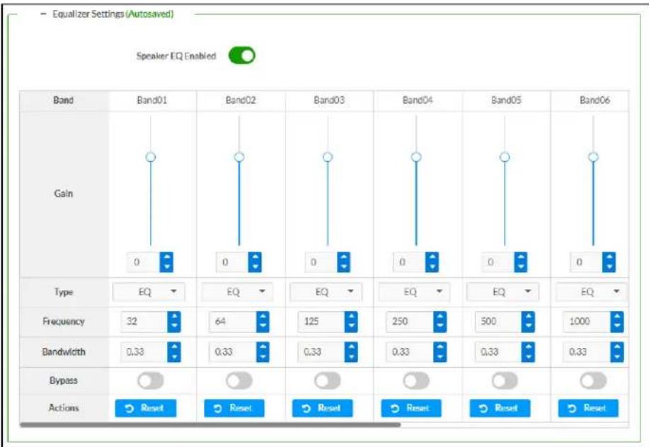
Each zone output of the DM-NAX-AMP-X300 has a dedicated ten-band equalizer that can be fully customized to tune the zone output signal to the needs of an install. Each band can have a discrete ga filter type, center frequency, and bandwidth set, and can also be bypassed. The equalizer itself can also be bypassed using the Speaker EQ Enabled toggle.
- Set the Speaker EQ Enabled toggle to the right position to enable the equalizer. Set the toggle to the left position to bypass the equalizer.
NOTE: When Speaker EQ Enabled is disabled, all equalizer bands are bypassed. This is a quick way to perform A/B testing of the entire EQ curve.
- With the Speaker EQ Enabled toggle in the right position, do the following to configure a given equalizer band:
a. To set a band's gain, do one of the following:
- Move the Gain slider up to increase or down to decrease the gain.
- Click the arrows to increase or decrease the gain. Values range from -40 dB to 20 dB, adjustable in increments of 0.1 dB.
- Manually enter a value in the Gain field.
b. Select a filter type from the Type drop-down menu. By default, all bands are set to the EQ filter type. Some filter types will disable other settings in their respective band while enabled. For example, selecting the LowPass filter type for a band will disable that band's Gain and Bandwidth settings, since the LowPass filter applies a fixed roll-off slope at a set frequency. The available filter types are:
- EQ: a fully parametric filter that can boost or cut a range of frequencies.
- Notch: a parametric filter designed to more precisely cut a frequency or range of frequencies. A notch filter can achieve a narrower bandwidth than the standard EQ parametric filter type.
- TrebleShelf: a filter that boosts or cuts all frequencies above a set frequency by a set gain.
- BassShelf: a filter that boosts or cuts all frequencies below a set frequency by a set gain.
- LowPass: a filter that fully cuts all frequencies above a set frequency using a fixed roll-off slope of -12 dB per octave.
- HighPass: a filter that fully cuts all frequencies below a set frequency using a fixed roll-off slope of -12 dB per octave.
c. Set a center frequency for the equalizer band to tune a specific portion of the audible frequency spectrum. To set the center frequency, do one of the following:
- Click the arrows to increase or decrease the frequency. Values range from 20 Hz to 20 kHz, adjustable in increments of 1 Hz. Each band has a default center frequency that will be applied if the Reset button at the bottom of the band is clicked.
- Manually enter a value in the Frequency field.
d. Set a bandwidth to determine how wide of a frequency range is effected by the equalizer band. To set the bandwidth, do one of the following:
- Click the arrows to increase or decrease the bandwidth. Values range from 0.1 octaves to 4.0 octaves, adjustable in increments of 0.1 octave.
- Manually enter a value in the Bandwidth field.
e. The individual Bypass controls allow you to bypass a single band of equalization at a time for more granular A/B testing of a single filter. Set a band's Bypass toggle to the right position to bypass that band. Set the toggle to the left position to disable the bypass. By default, Bypass is disabled.
f. Each equalizer band has a Reset button that will reapply the default settings for that band.
Click Done to return to the Settings tab of the web user interface.
Bussing

The bussing feature on DM NAX devices allows an integrator to assign any number of selected zones to a fixed group of zones (bus). Zones in a bus track the other zones' volume and routing. For example,
when the source or volume for one zone in the bus is adjusted, all other zones in that bus receive the same adjustment. You can create a single output bus on the DM-NAX-AMP-X300.
Configure Bussing
- If needed, enter a friendly name for each bus in its Name field.
- Select any number of zones from the Included Zones drop-down menu.
Inputs
The Inputs section is used to configure the Name, Compensation, and Mute attributes of the available analog, digital, and media streaming inputs on the DM-NAX-AMP-X300.
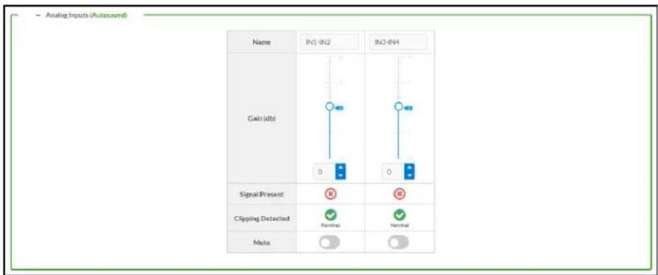
- If needed, enter a friendly name for each input in its Name field.
- To set a level compensation adjustment for a given input, do one of the following:
- Move the Compensation slider up to increase or down to decrease the compensation.
Compensation increases or decreases the level of the incoming audio signal on any of the physical inputs on the device's rear panel.
- Click the db arrows to increase or decrease the compensation. Values range from -10 dB to 10 dB, adjustable in increments of 1 dB.
-
Manually enter a value in the Compensation field.
-
To mute the signal from the corresponding input, click the Mute button. To disable the mute, click the Muted button. By default, Mute is disabled.
Monitor the device's input signals using the indicators in the Signal Present and Clipping Detected rows:
• Signal Presence indicates whether or not a signal is detected in that zone.
- Clipping Detected indicates if the signal is Clipping or Nominal (non-clipping).
NAX Streams
Each local input of the DM-NAX-AMP-X300 can be made available as a DM NAX audio-over-IP stream.
The DM-NAX-AMP-X300 also supports parallel DM NAX streams for each zone output, enabling an additional transmit stream per output to mirror all routes and DSP settings of its respective zone. These parallel streams enable control of the audio signal to third-party uncontrolled AES67 devices receiving audio from the DM-NAX-AMP-X300.
NOTES:
- Under the Transmitters section (see Configure Transmitters), the last two listed transmitters are dedicated to parallel zone outputs.
• To configure the DSP settings, see Zone Settings.
Click NAX Streams to display the following information.
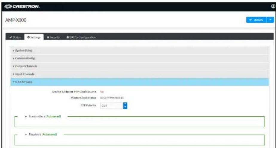
- Device is Master PTP Clock Source indicates whether the device is the master for PTP on the network. Yes will be displayed in green when the local DM-NAX-AMP-X300 is the PTP clock master and No will be displayed in red when another PTP clock on the network is operating as the master clock.
- Master Clock Status displays the Master Clock ID of the device on the network that acts as the Master Clock.
- PTP Priority: This sets the priority of the local DM NAX device's PTP clock relative to other clocks on the network. The default setting is 254 (one increment higher than the lowest possible value) so that the DM-NAX-AMP-X300 will only operate as clock master if no other PTP master is present on the network. Valid values range from 1 to 255.
Configure Transmitters

To configure a DM NAX transmit stream, do the following.
- Enter a valid multicast address in the NAX Stream Address field.
-
Enter a name in the NAX Stream Name field by which the stream can be identified. This stream name is associated with the DM NAX stream's multicast address by other DM NAX or AES67 devices, like a device hostname that resolves to a given IP address.
-
Status indicates whether a stream is transmitting or not. When the stream has started or stopped, the Status column will update accordingly.
-
Click the configure button (💡) in the Actions column. The Configure dialog appears:

-
Set the Auto Initiation toggle to the right position to enable auto initiation. Set the toggle to the left position to disable auto initiation.
-
If Auto Initiation is enabled for a given stream, the stream will begin transmitting automatically and will be available as a multicast stream on your network at the specified multicast address.
-
If Auto Initiation is disabled for the input, the stream will not begin transmitting until it is manually initiated.
-
To set the port number, do one of the following:
-
Click the arrows to increase or decrease the port number by increments of 1.
-
Manually enter a port number in the Port field. The default port number for DM NAX streams is 5004.
-
Click OK to save or click Cancel to cancel the changes.
Configure Receivers

- Enter the multicast address of a transmitting stream in the Requested Stream Address field to subscribe the receiver to the stream.
- Click the configure button (💡) in the Actions column. The Configure dialog appears:

-
Set the Auto Initiation toggle to the right position to enable auto initiation. Set the toggle to the left position to disable auto initiation.
-
If Auto Initiation is enabled, the stream will begin automatically when the receiver subscribes to the transmitter.
• If Auto Initiation is disabled, the stream will not begin until it is manually initiated. -
To set the port number, do one of the following:
-
Click the arrows to increase or decrease the port number by increments of 1.
• Manually enter a port number in the Port field. The default port number is 5004. -
Click OK to save or click Cancel to cancel the changes.
Routing
The Routing section is used to route a local input or AES67 stream to a Zone on the DM-NAX-AMP-X300.
NOTE: To receive an AES67 stream from Dante devices, see OLH 1001151.

To route an input to a zone, click the box in the routing matrix where the zone's row overlaps the corresponding input's column. Once a route is made, appears. To break a given route click or . To route a single input to all zones, click on the icon under the input's name.
Use the arrows◀ or ▶ at the top of the matrix to change pages to view all available inputs.
Port Selection
The Port Selection feature allows the device's internal network traffic to be managed and segregated based on traffic type. Internal VLANs are used to segment device management and streaming service traffic to a separate physical device Ethernet port than audio-over-IP streaming traffic. With Port Selection enabled on all DM NAX devices on a network, DM NAX and AES67 network traffic can be physically separated from the control network onto a dedicated audio network.

To configure Port Selection:
- Set the Port Selection toggle to the right position to enable Port Selection. Set the toggle to the left position to disable Port Selection. By default, Port Selection is disabled.
NOTE: Ports 1 and 2 correspond to the Ethernet adapters labeled 1 and 2 on the rear panel of the DM-NAX-AMP-X300, respectively.
- With Port Selection enabled, select an Ethernet port from the Management drop-down menu to designate which Ethernet port on the rear panel of the device will handle network traffic relating to device configuration and the device's connection to a control system.
NOTE: The Management port determines your connection to the web interface. Changing the port value can result in losing your connection to the device via the web interface.
-
With Port Selection enabled, select an Ethernet port from the Audio/NAX drop-down menu to designate which Ethernet port on the rear panel of the device will handle audio-over-IP streaming network traffic.
-
Click Save changes to apply the new settings.
NOTE: Making changes to Port Selection settings will require a reboot.
Security
Click the Security tab to configure security for users and groups and to allow different levels of access to the DM-NAX-AMP-X300 functions. By default, security is disabled.
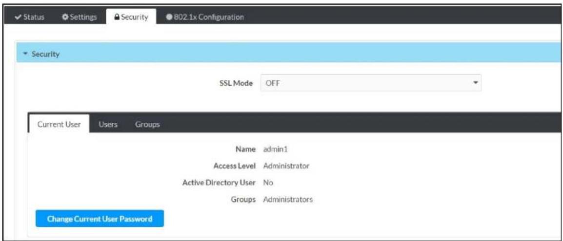
Select Encrypt and Validate, Encrypt, or OFF in the SSL Mode drop-down menu, to specify whether to use encryption. By default, SSL Mode is set to OFF.
Current User
Click the Current User tab to view read-only information or to change the password for the current user.
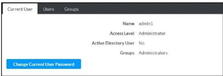
- Click the Change Current User Password button to provide a new password for the current user.
- In the Change Password dialog, enter the current password in the Current Password field, the new password in the Password field, and then re-enter the same new password in the Confirm Password field.

- Click OK to save or click Cancel to cancel the changes.
Users
Click the Users tab to view and edit user settings. The Users tab can be used to add or remove local and Active Directory users and preview information about users.

Use the Search Users field to enter search term(s) and display users that match the search criteria.
If users listed in the Users table span across multiple pages, navigate through the list of users by clicking a page number or by using the left or right arrows at the bottom of the Users pane to move forward or backward through the pages.
Each page can be set to display 5, 10, or 20 users by using the drop-down menu to the right of the navigation arrows.
Information about existing users is displayed in table format and the following details are provided for each user.
- Username: Displays the name of the user.
• AD User: Displays whether the user requires authentication using Active Directory.
Click the corresponding button in the Actions column to view detailed user information or to delete the user.
To create a new user, click the Create User button.
Create a New Local User
- Click the Create User button in the User tab.
- In the Create User dialog, enter the following:
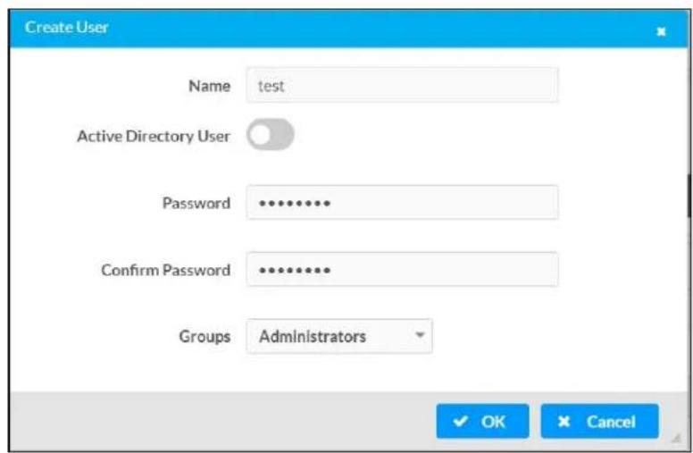
a. Enter a user name in the Name field. A valid user name can consist of alphanumeric characters (letters a-z, A-Z, numbers 0-9) and the underscore "_" character.
b. Enter a password in the Password field; re-enter the same password in the Confirm Password field.
c. Assign the access level by selecting one or more groups from the Groups drop-down list.
NOTE: Make sure that the Active Directory User toggle is disabled.
- Click OK to save or click Cancel to cancel the changes.
Add an Active Directory User
Users cannot be created or removed from the Active Directory server, but access can be granted to an existing user in the Active Directory server.
To grant access to an Active Directory user, you can either add the user to a local group on the DM-NAX-AMP-X300, or add the Active Directory group(s) that they are a member of to the DM-NAX-AMP-X300.
To add an Active Directory user.
- Click the Create User button.
- In the Create User dialog, enter the following.

a. Enter a user name in the Name field in the format "Domain\UserName", for example "crestronlabs.com\JohnSmith". Valid user names can contain alphanumeric characters (letters a-z, A-Z, numbers 0-9) and the underscore "." character.
b. Select one or more groups from the Groups drop-down list.
NOTE: Make sure that the Active Directory User toggle is set to enabled.
- Click OK to save or click Cancel to cancel the changes.
Delete User
Click the trashcan button (☐) in the Actions column to delete the user. Click Yes when prompted to delete the user or No to cancel the deletion.
After a user is removed from a group, they lose any access rights associated with that group. Note that the user account is not deleted by the delete user operation.
View User Details
Click the information button (8) in the Actions column to view information for the selected user. The User Details dialog displays the following information for the selected user.
- Name: Displays the name of the selected user.
• Active Directory User: Displays whether the user is an Active Directory user. - Group: Displays group(s) the selected user is part of.

Click OK to close the User Details dialog and to return to the Users tab.
Update User Details
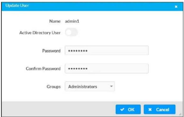
- Click the edit button() in the Actions column to update information for the selected user.
- Enter a password in the Password field; re-enter the same password in the Confirm Password field.
- Select one or more groups to assign the user to from the Groups drop-down list.
- Click OK to save or click Cancel to cancel the changes.
The Update User dialog also displays the following read-only information for the selected user.
• Name: Displays the name of the user.
• Active Directory User: Displays whether the user is an Active Directory user.
Groups
Click the Groups tab to view and edit group settings. The Groups tab can be used to add local and Active Directory groups, remove local and Active Directory groups, and preview information about a group.
Use the Search Groups field to enter search term(s) and display groups that match the search criteria.

If groups listed in the Groups table span across multiple pages, navigate through the groups by clicking a page number or by using the left or right arrows at the bottom of the Groups pane to move forward or backward through the pages.
Additionally, each page can be set to display 5, 10, or 20 groups by using the drop-down menu to the right of the navigation arrows.
Existing groups are displayed in a table and the following information is provided for each group:
- Group Name: Displays the name of the group.
• AD Group: Displays whether the group requires authentication using Active Directory. - Access Level: Displays the predefined access level assigned to the group (Administrator, Programmer, Operator, User, or Connect).
Click the corresponding button in the Actions column to view detailed group information (☐) or to delete (☐) selected group.
Click on the Create Group button in the Groups tab to create new group.
Create Local Group

- Click the Create Group button.
- In the Create Group dialog, enter the following:
a. Enter the group name in the Name field.
b. Assign the group access level by selecting a predefined access level (Administrator, Connect, Operator, Programmer, User) from the Access Level drop-down list.
NOTE: Make sure that the Active Directory Group toggle is disabled.
- Click OK to save. Click Cancel to cancel the changes.
Add Active Directory Group
A group cannot be created or removed from the Active Directory server, but access can be granted to a existing group in Active Directory.
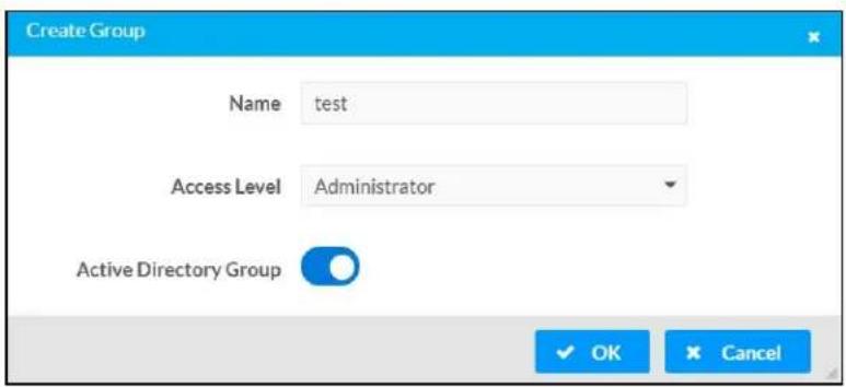
Once the group is added, all members of that group will have access to the DM-NAX-AMP-X300.
- Click the Create Group button.
- In the Create Group dialog enter the following:
a. Enter the group name in the Name field, for example "Engineering Group". Note that group names are case sensitive; a space is a valid character that can be used in group names.
- Assign the group access level by selecting a predefined access level (Administrator, Connect, Operator, Programmer, User) from the Access Level drop-down list.
NOTE: Make sure that the Active Directory Group toggle is enabled.
- Click OK to save. Click Cancel to cancel the changes.
Delete a Group
Click the trashcan button (☐) in the Actions column to delete a group. Click Yes when prompted to delete the group or No to cancel the deletion.
When a group is deleted, users in the group are not removed from the device or Active Directory server. However, because a user's access level is inherited from a group(s), users within the deleted group will lose access rights associated with the group.
View Group Details
Click the information button (6) in the Actions column to view information for the selected group. The Group Details dialog lists the following information for the selected group.

- Name: Displays the name of the group.
- Access Level: Displays the access level of the group and its users.
• Active Directory Group: Displays whether the group is an Active Directory group.
Click OK to close the Group Details dialog and to return to the Groups tab.
802.1x Configuration
The DM-NAX-AMP-X300 has built-in support for the 802.1X standard (an IEEE network standard designed to enhance the security of wireless and Ethernet LANs. The standard relies on the exchange of messages between the device and the network's host, or authentication server), allowing communication with the authentication server and access to protected corporate networks.

To Configure 802.1X Authentication
- Set the IEEE 802.1X Authentication toggle to enabled. This will enable all options on the 802.1X dialog.
- Select the Authentication method: EAP-TLS Certificate or EAP-MSCHAP V2 Password according to the network administrator's requirement.
-
Do either one of the following:
-
Select EAP-TLS Certificate: Click Action/Manage Certificates to upload the required machine certificate. The machine certificate is an encrypted file that will be supplied by the network administrator, along with the certificate password.
-
Select EAP-MSCHAP V2 Password: Enter the username and password supplied by the network administrator into the Username and Password fields. This method does not require the use of a machine certificate, only the user name and password credentials.
-
Select the OCSP State: If using OCSP, select All, Required, or Optional. To disable OCSP, select Off.
-
If you enabled the Enable Authentication Server Validation option, this will enable the Select Trusted Certificate Authoritie(s) list box which contains signed Trusted Certificate Authorities (CAs) preloaded into the DM-NAX-AMP-X300.
Select the check box next to each CA whose certificate can be used for server validation, as specified by the network administrator.
If the network does not use any of the listed certificates, the network administrator must provide a certificate, which must be uploaded manually via the Manage Certificates functionality.
- If required, type the domain name of the network in the Domain field.
- When the 802.1X settings are configured as desired, click Save Changes to save the changes to the device and reboot it. Click Revert to cancel any changes.
Access the Web Interface With the Crestron Toolbox Application
To access the web interface by opening a web browser within the Crestron Toolbox™ application, do the following:
-
Open the Crestron Toolbox application.
-
From the Tools menu, select Device Discovery Tool. You can also access the Device Discovery Tool by clicking the Device Discovery Tool button ( ) in the Crestron Toolbox toolbar. The DM-NAX-AMP-X300 is discovered and listed in the device list on the left side of the screen. The associated host name, IP address, and firmware version are also displayed.
NOTE: If there is security software running on the computer, a security alert might be displayed when the Crestron Toolbox application attempts to connect to the network. Make sure to allow the connection, so that the Device Discovery Tool can be used.
-
In the Device Discovery Tool list, double-click your device.
-
Enter your credentials in the Authentication Required dialog that opens, and then click Log In.
-
Click the Web Configuration button in the Configuration page displayed on the left side of the Device Discovery Tool.
DM-NAX-AUD-IO
This section describes how to configure the DM-NAX-AUD-IO.
Web Interface Configuration
The DM-NAX-2XLRI-1G web interface allows you to view status information and configure network and device settings.
Access the Web Interface
To access the web interface, do either of the following:
- Access the Web Interface with a Web Browser on page 474
- Access the Web Interface With the Crestron Toolbox™ Application on page 528
The web interface is accessed from a web browser. The following table lists operating systems and their corresponding supported web browsers.
Operating System and Supported Web Browsers
| OPERATING SYSTEM SUPPORTED WEB BROWSERS | |
| Windows® operating system | ChromeTM web browser, version 31 and laterFirefox® web browser, version 31 and laterInternet Explorer web browser, version 11 and laterMicrosoft Edge web browser |
| macOS® operating system | Safari® web browser, version 6 and laterChrome web browser, version 31 and laterFirefox web browser, version 31 and later |
Access the Web Interface with a Web Browser
- Enter the IP address of the DM-NAX-AUD-IO into a web browser.
NOTE: To obtain the IP address, use the Device Discovery Tool option in Crestron Toolbox™ application or an IP scanner application.
- If you are creating a user account for the first time, do the following; otherwise, skip to step 3.
a. Enter a username in the Username field.
b. Enter a password in the Password field.
c. Re-enter the same password in the Confirm Password field.
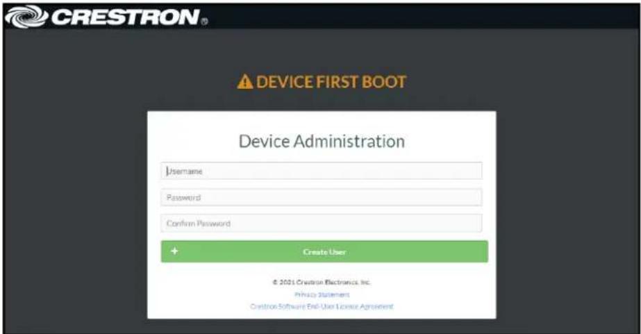
d. Click Create User. The Device Administration page appears.

- Enter the username in the Username field.
- Enter the password in the Password field.
- Click Sign In.
Action
The Action drop-down menu is displayed at the top right side of the interface and provides quick access to common device functions:
- Save Changes
- Revert
- Reboot
- Restore
- Update Firmware
- Download Logs
- Manage Certificates

Save Changes
Click Save Changes to save any changes made to the configuration settings.
Revert
Click Revert to revert the device back to the last saved configuration settings.
Reboot the DM-NAX-AUD-IO
Certain changes to the settings may require the DM-NAX-AUD-IO to be rebooted to take effect. To reboot the device, do the following:
- Click Reboot in the Actions drop-down menu. The Confirmation message box appears.

- Click Yes, Reboot Now to reboot the device. The Reboot message box appears.
Wait for the device reboot to complete before attempting to reconnect to the device.
Restore to Factory Default Settings
- Click Restore in the Actions drop-down menu to restore the settings of the DM-NAX-AUD-IO to factory defaults.
NOTE: When settings are restored, all settings, including the network settings, will revert to the factory default. If a static IP address is set, restoring the device to factory default settings will revert the IP address to the default DHCP mode.

- Click Yes in the Confirmation dialog to restore the DM-NAX-AUD-IO to factory settings. Click No to cancel the restore operation.
A dialog is displayed again, indicating that the restore process was successful and that the device rebooted.
You can also restore to factory settings by pressing and holding the SETUP button on the rear panel of the device with power disconnected then connect the power supply and continue to hold SETUP button for 30 seconds.
Update Firmware
-
Click Update Firmware in the Actions drop-down menu.
-
In the Firmware Upgrade dialog, click + Browse.
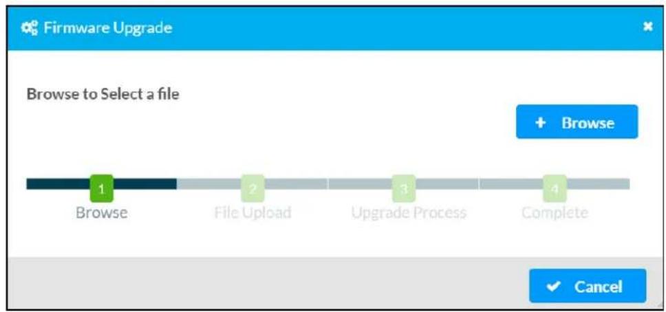
- Locate and select the desired firmware file, and then click Open. The selected firmware file name is displayed in the Firmware Upgrade dialog.
- Click Load and wait for the progress bar to complete and for the OK button in the message to become clickable.
- Click OK. The device with new firmware can now be accessed.
Download Logs
- Click Download Logs in the Actions drop-down menu to download the device message logs for diagnostic purposes.
The log file is downloaded to the Downloads folder of the PC.
Manage Certificates
Use the Manage Certificates dialog to add, remove, and manage certificates used in 802.1x and other protected networks.
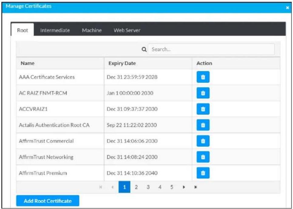
-
Click Manage Certificates in the Actions drop-down menu. The following certificate tabs are displayed:
-
Root: The Root certificate is used by the DM-NAX-AUD-IO to validate the network's authentication server. The DM-NAX-AUD-IO has a variety of Root certificates, self-signed by trusted CAs (Certificate Authorities) preloaded into the device. Root certificates must be self-signed.
- Intermediate: The Intermediate store holds non self-signed certificates that are used to validate the authentication server. These certificates will be provided by the network administrator if the network does not use self-signed Root certificates.
- Machine: The machine certificate is an encrypted PFX file that is used by the authentication server to validate the identity of the DM-NAX-AUD-IO. The machine certificate will be provided by the network administrator, along with the certificate password. For 802.1x, only one machine certificate can reside on the device.
- Web Server: The Web Server certificate is a digital file that contains information about the identity of the web server.
To Add Certificates
- Click the corresponding certificate tab.
- Click the Add Root Certificate button.
- Click the + Browse button.
- Locate and select the file, and then click the Open button.
NOTE: If the certificate is a Machine Certificate, enter the password provided by the network administrator.
- Click OK. This will add the certificate to the list box, displaying the file name and expiration date.
The certificate is now available for selection and can be loaded to the device.
To Delete Certificates
- Click the corresponding certificate tab.
- Click the trashcan button ( ) in the Actions column to delete the certificate.
- Click Yes when prompted to delete the certificate or No to cancel the deletion.
Status
The Status tab is the first page displayed when opening the interface of the DM-NAX-AUD-IO. It displays general information about the DM-NAX-AUD-IO (such as Model Name, Firmware Version, and Serial Number), current network settings (such as Host Name and IP Address, etc.), and input and output ports' current status.
The Status tab can be accessed at any time by clicking the Status tab of the DM-NAX-AUD-IO interface.

Information displayed on the Status tab is organized into different sections.
Device
The Device section displays the Model, Firmware Version, and Serial Number of the DM-NAX-AUD-IO.

Click + More Details to review additional information about the DM-NAX-AUD-IO.
![— More Details DM-NAX-AUD-IO 1.0.0033.11191 Build Feb 13 2024 (531246) Updater 1.0.0033.11191 Bootloader 1.0.00 CCUI Version 1.1327.1 XIOSDK 3.8.2 IoTSDK 1.11.0 Build time 11:19:07 Product ID 0x7A06 Revision ID 0x0100 HDCP2X-SKE HDCP2X-SKE HDCP2X-SKE [v9.0000.00000.#FFFFFFF] PRE-BOOT [v9.0000.00000] BOOTLOADER [v9.0000.00000] ctrl-audio-dsp-0 FW v11 (Driver v4.00) ctrl-axtelkin-pps Driver v1.1 ctrl-prod-info Driver v3.0 PUF 1.0.0033.11191 Forced Auth Mode True](/content/2026/05/985127/images/b53aec0da843ec8e38090eb41936d83cfbff108ff3edabefddbb2cdcb9334627.jpg)
Network
The Network section displays network-related information about the DM-NAX-AUD-IO, including the Hostname, Domain Name, and DNS Servers.

NOTE: By default, the host name of the DM-NAX-AUD-IO consists of the model name followed by the MAC address of the device. For example, DM-NAX-AUD-IO-00107FB58088.
Click + Adapter 1 to display an expanded section that shows additional information. If + Adapter 1 is selected, click - Less details to collapse the section.
Control System
The Control System section displays connection information, consisting of the following:

- Encrypt Connection: ON or OFF
• IP ID: Reports the currently used IP ID of the DM-NAX-AUD-IO
• IP Address/Hostname: The IP address of the control system
• Room ID: Displays the room ID
• Status: OFFLINE or ONLINE
Settings
The Settings tab enables configuration of the DM-NAX-AUD-IO settings. The Settings page can be accessed at any time by clicking the Settings tab of the DM-NAX-AUD-IO interface.
Many options in the Settings tab are exclusive to a specific device mode: Residential or Commercial. The DM-NAX-AUD-IO is in Commercial mode by default.
This section provides the following information:
• Commercial Mode on page 482
• Residential Mode on page 500
Commercial Mode
This section provides the following information:
• System Setup on page 482
• Commissioning on page 487
• Output Channels on page 488
• Input Channels on page 495
• DM NAX Streams on page 496
- Mixing on page 499
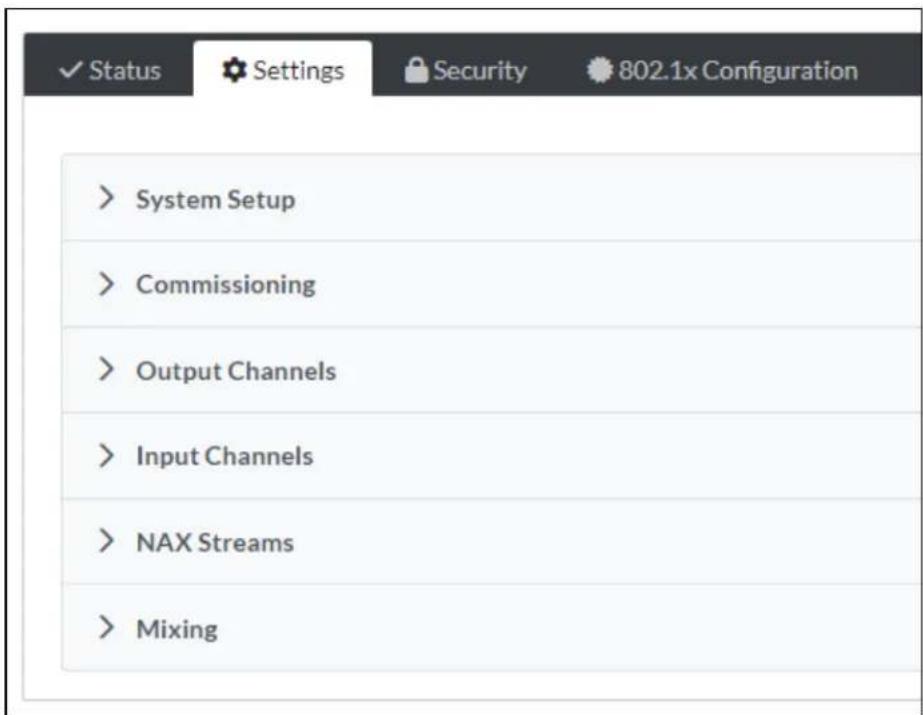
System Setup
The System Setup section contains settings for Date/Time, Auto Update, Network, and Control System.

Date/Time
Use the Date/Time tab to configure the date and time settings of the DM-NAX-AUD-IO.
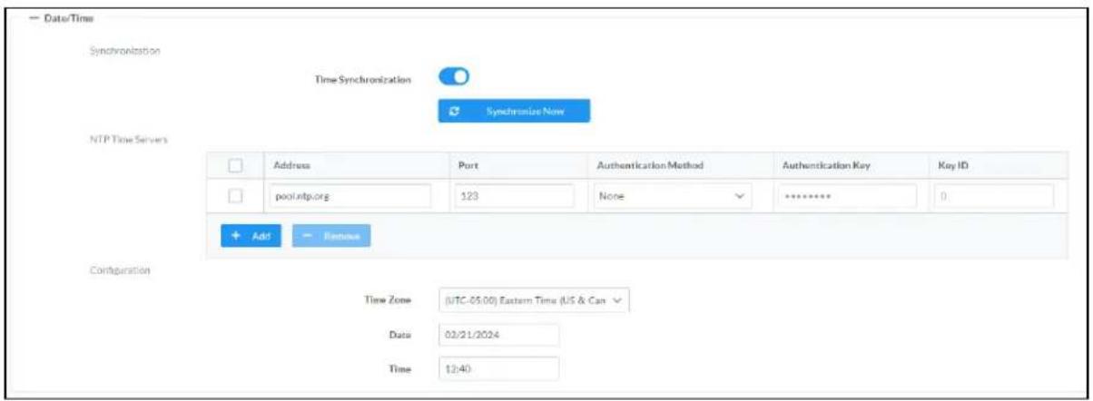
Time Synchronization
- Set the Time Synchronization toggle to the right position to enable or left position to disable time synchronization. By default, time synchronization is enabled.
- In the NTP Time Servers table, enter the URL of a NTP (Network Time Protocol) or SNTP (Simple Network Time Protocol) server. Up to three time servers can be added on a device.
- Click Synchronize Now to perform time synchronization between the device's internal clock and the time server.
Time Configuration
- Click on the Time Zone drop-down menu to select the applicable time zone.
- In the Date field, enter the current date.
- In the Time (24hr Format) field, enter the current time in 24-hour format.
Click the Save Changes button to save the settings.
Click Revert from the Actions drop-down menu to revert to the previous settings without saving.
Auto Update
The DM-NAX-AUD-IO can automatically check for and install firmware updates at scheduled intervals via the Auto Update feature.

- Set the Auto Update toggle to the right position to enable Auto Update.
- Define the URL to download the updates by doing either of the following:
a. Use the default URL to download the updates from the Crestron server.
b. Use a custom URL. Set the Custom URL toggle to the right position to enable a custom URL. In the Custom URL Path text box, enter the path to a custom manifest file in the F or SFTP URL format. Use the Crestron Auto Update Tool to generate a custom manifest file, then store the file on an FTP (File Transfer Protocol) or SFTP (Secure File Transfer Protocol) server.
- Set a schedule for the automatic firmware update by doing either of the following:
a. Select the desired Day of Week and Time of Day (24-hour format) values.
b. Set the Poll Interval by entering a value from 60 to 65535 minutes. A value of 0 disables the Poll Interval.
- Click Save Changes.
Clicking Update Now causes the device to check for a firmware update immediately. If a schedule was set in step 4 above, that schedule still remains in effect.
Network
The Network tab contains network-related settings for the DM-NAX-AUD-IO, including the Hostname, Domain, Primary Static DNS, and Secondary Static DNS.

NOTE: By default, the hostname of the DM-NAX-AUD-IO consists of the model name followed by the MAC address of the device. For example, DM-NAX-AUD-IO-00107FB58088.
Adapter 1
The Adapter 1 subheading contains settings for DHCP, IP Address, Subnet Mask, and Default Gateway of Ethernet adapter 1 on the rear panel of the device.
NOTE: DM NAX devices' internal processes use IP addresses in the 10x10 range. This IP range should be avoided when addressing DM NAX devices to prevent conflicts.
Set the DHCP toggle to enabled (right) or disabled (left) to specify whether the IP address of the DM-NAX-AUD-IO is to be assigned by a DHCP (Dynamic Host Configuration Protocol) server.
- Enabled: When DHCP is enabled (default setting), the IP address of the DM-NAX-AUD-IO is automatically assigned by a DHCP server on the local area network (LAN).
- Disabled: When DHCP is disabled, manually enter information in the following fields:
° Primary Static DNS: Enter a primary DNS IP address.
Secondary Static DNS: Enter a secondary DNS IP address.
IP Address: Enter a unique IP address for the DM-NAX-AUD-IO.
- Subnet Mask: Enter the subnet mask that is set on the network.
Default Gateway: Enter the IP address that is to be used as the network's gateway.
To save any new network entries, click Save Changes.
Control System
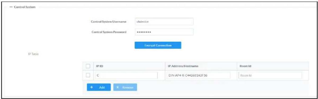
- Click the Encrypt Connection button to navigate to the Security tab to configure encryption settings.
- Enter the username in the Control System Username field.
- Enter the password in the Control System Password field.
- Enter the Room ID in the Room ID field.
- Enter the IP ID of the DM-NAX-AUD-IO in the IP ID field.
- Enter the IP address or hostname of the control system in the IP Address/Hostname field.
- Click the Save Changes button to save the new entries. The Control System Save message box appears, indicating that the control system settings were saved successfully. Click the Revert button to revert to the previous settings without saving.
Cloud Settings

Set the Cloud Settings toggle to enabled (right) or disabled (left) to specify whether the DM-NAX-AUD-IO can communicate with the XiO Cloud® platform.
Device Modes
Use the Device Modes tab to configure the Application Mode of the DM-NAX-AUD-IO.

The Application Mode determines which options and controls are available.
- Select Residential (Standard) or Commercial (Advanced). A Reboot confirmation message box appears.

- Click Yes, Reboot Now to reboot the device into the selected mode. The Reboot message box appears.
- Wait for the device reboot to complete before attempting to reconnect to the device.
By default, the DM-NAX-AUD-IO is set to Commercial (Advanced) mode.
Commissioning
The Commissioning section provides a quick way to automatically assign multicast addresses to the device's internal audio-over-IP stream transmitters.

Click Assign Addresses to give each DM NAX transmitter in the DM-NAX-AUD-IO a unique multicast address beginning with the specified Starting Multicast Address. The valid range for Starting Multicast Address is 239.8.0.0 to 239.255.255.254.
NOTE: This will begin transmitting multicast traffic on your network, refer to the DM NAX Audio-over-IP System Design Guide document for details.
Output Channels
The Zones section contains the Volume and Mute settings for all zone outputs of the device, as well as an Edit option for more advanced settings within each zone.

bar
| Name | LineOutLeft | LineOutRight | StreamOut1Ch1 | StreamOut1Ch2 | |---|---|---|---|---| | Volume (%) | 30 | 30 | 80 | 80 | | Signal Presence | | | | | | Signal Level | Nominal | Nominal | Nominal | Nominal | | Mute | | | | | | Action | Edit | Edit | Edit | Edit |Signal Presence indicates whether or not an audio signal is detected in that zone.
Signal Level indicates if the signal is Clipping or Nominal (non-clipping).
- Nominal: The signal level is within normal operating bounds and below the clipping threshold.
- Clipping: The signal level is clipping or above the -3 dB warning threshold and in danger of clipping.
Give each zone a friendly name using the Name column of the Zones table. If the device is paired with a control system, these names may be overwritten by the control system's program.
To configure the zone volume, do one of the following:
- Move the Volume slider up to increase or down to decrease the zone volume.
- Click the % arrows to increase or decrease the zone volume. Values range from 0 to 100%, adjustable in increments of 1%.
- Manually enter a value in the Volume field.
To mute all audio output from a zone, click its respective Mute button. To unmute the zone, click the Muted button.
Click Edit to view additional Zone and Output options.
Zone Settings
To configure the settings for an output channel, click the Edit button. The Edit Zone window appears.
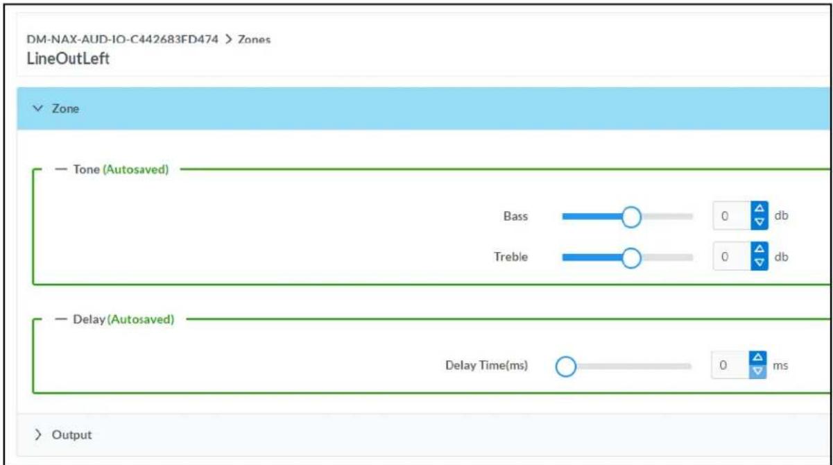
Zone
Click Zone to access the settings for Tone and Delay.
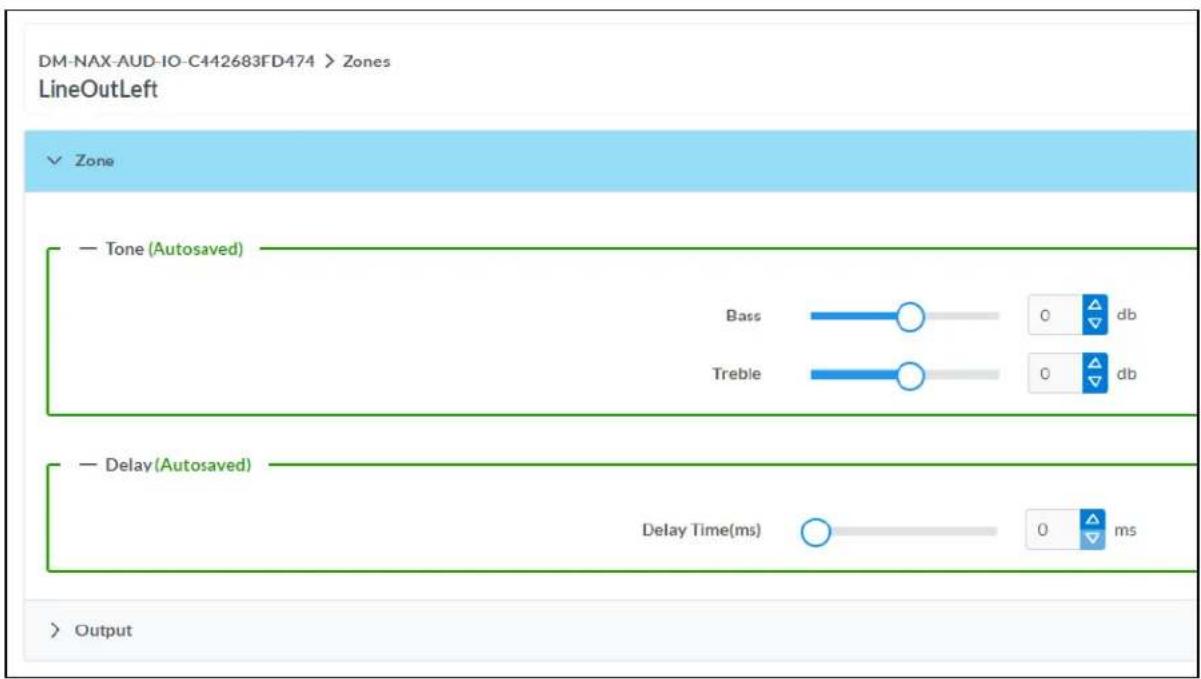
Tone

- Bass: To adjust the bass, do one of the following:
- Move the Bass slider to the right to increase or to the left to decrease the bass db.
- Click the db arrows to increase or decrease the db. Values range from -12 db to 12 db, adjustable in increments of .1 db.
- Manually enter a value in the Bass field.
- Treble: To adjust the treble, do one of the following:
- Move the Treble slider to the right to increase or to the left to decrease the treble db.
- Click the db arrows to increase or decrease the db. Values range from -12 db to 12 db, adjustable in increments of .1 db.
- Manually enter a value in the Treble field.
Delay

To set the delay, do one of the following:
- Move the Delay Time(ms) slider to the right to increase or to the left to decrease the delay time.
- Click the ms arrows to increase or decrease the delay. Values range from 0 ms to 85 ms, adjustable in increments of 1 ms.
- Manually enter a value in the Delay Time(ms) field.
NOTE: The Delay feature is only available on the line level output channels.
Output
Click Output to access the settings for Minimum/Maximum Volume, Signal, and the output Equalizer.

Minimum/Maximum Volume
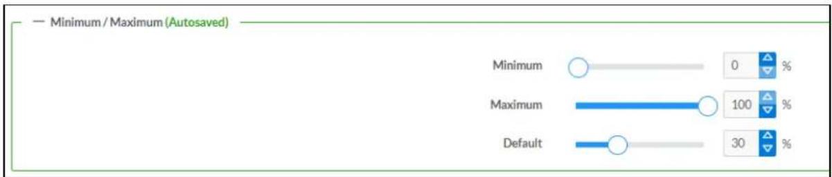
-
To set the minimum volume of the zone, do one of the following:
-
Move the Minimum slider to the right to increase or to the left to decrease the minimum volume.
- Click the % arrows to increase or decrease the minimum volume. Values range from 0 to 50%, adjustable in increments of 1%.
-
Manually enter a value in the Minimum field.
-
To set the maximum volume of the zone, do one of the following:
-
Move the Maximum slider to the right to increase or to the left to decrease the maximum volume.
- Click the % arrows to increase or decrease the maximum volume. Values range from 70 to 100%, adjustable in increments of 1%.
- Manually enter a value in the Maximum field.
NOTE: When a Minimum and Maximum volume are set, the 1-100% range represented by the Zone and Default volume controls are scaled to the range set. For example, if a Minimum of 10% and a Maximum of 80% are set for a zone, the 1-100% range of the Zone volume control is scaled to the 10%-80% range set as the Minimum and Maximum.
-
To set the default volume of the zone, do one of the following:
-
Move the Default slider to the right to increase or to the left to decrease the default volume.
- Click the % arrows to increase or decrease the default volume. Values range from 0 to 50% adjustable in increments of 1%.
- Manually enter a value in the Default field.
NOTE: The Default volume is applied as the Zone volume any time the zone receives a source route and no source was previously routed to that zone.
Signal

The Signal section is a read-only field that displays the Signal and Clipping status of the zone output.
- If an output signal is present but not clipping, Signal will display Present in green and Clipping will display None in green.
- If an output signal is present and clipping, Signal will display Present in green and Clipping will display Present in red.
- If no output signal is detected, Signal will display Not Present in red and Clipping will display None in green.
Equalizer Settings

bar
Speaker EQ Enabled | Band | Band01 | Band02 | Band03 | Band04 | Band05 | Band06 | Band07 | Band08 | Band09 | Band10 | |---|---|---|---|---|---|---|---|---|---|---| | Gain | 0 | 0 | 0 | 0 | 0 | 0 | 0 | 0 | 0 | 0 | | Type | EQ ▼ | EQ ▼ | EQ ▼ | EQ ▼ | EQ ▼ | EQ ▼ | EQ ▼ | EQ ▼ | EQ ▼ | EQ ▼ | | Frequency | 32 | 64 | 125 | 250 | 500 | 1000 | 2000 | 4000 | 8000 | 16000 | | Bandwidth | 0.33 | 0.33 | 0.33 | 0.33 | 0.33 | 0.33 | 0.33 | 0.33 | 0.33 | 0.33 | | Bypass | Reset | Reset | Reset | Reset | Reset | Reset | Reset | Reset | Reset | Reset | | Actions | Reset | Reset | Reset | Reset | Reset | Reset | Reset | Reset | Reset | Reset |Each output channel of the DM-NAX-AUD-IO has a dedicated ten-band equalizer that can be fully customized to tune the zone output signal to the needs of an install. Each band can have a discrete ga filter type, center frequency, and bandwidth set, and can also be bypassed. The equalizer itself can also be bypassed using the Speaker EQ Enabled toggle.
- Set the Speaker EQ Enabled toggle to the right position to enable the equalizer. Set the toggle to the left position to bypass the equalizer.
NOTE: When Speaker EQ Enabled is disabled, all equalizer bands are bypassed. This is a quick way to perform A/B testing of the entire EQ curve.
- With the Speaker EQ Enabled toggle in the right position, do the following to configure a given equalizer band:
a. To set a band's gain, do one of the following:
- Move the Gain slider up to increase or down to decrease the gain.
- Click the arrows to increase or decrease the gain. Values range from -40 dB to 20 dB, adjustable in increments of 0.1 dB.
- Manually enter a value in the Gain field.
b. Select a filter type from the Type drop-down menu. By default, all bands are set to the EQ filter type. Some filter types will disable other settings in their respective band while enabled. For example, selecting the LowPass filter type for a band will disable that band's Gain and Bandwidth settings, since the LowPass filter applies a fixed roll-off slope at a set frequency. The available filter types are:
- EQ: a fully parametric filter that can boost or cut a range of frequencies.
- Notch: a parametric filter designed to more precisely cut a frequency or range of frequencies. A notch filter can achieve a narrower bandwidth than the standard EQ parametric filter type.
- TrebleShelf: a filter that boosts or cuts all frequencies above a set frequency by a set gain.
- BassShelf: a filter that boosts or cuts all frequencies below a set frequency by a set gain.
- LowPass: a filter that fully cuts all frequencies above a set frequency using a fixed roll-off slope of -12 dB per octave.
- HighPass: a filter that fully cuts all frequencies below a set frequency using a fixed roll-off slope of -12 dB per octave.
c. Set a center frequency for the equalizer band to tune a specific portion of the audible frequency spectrum. To set the center frequency, do one of the following:
- Click the arrows to increase or decrease the frequency. Values range from 20 Hz to 20 kHz, adjustable in increments of 1 Hz. Each band has a default center frequency that will be applied if the Reset button at the bottom of the band is clicked.
- Manually enter a value in the Frequency field.
d. Set a bandwidth to determine how wide of a frequency range is effected by the equalizer band. To set the bandwidth, do one of the following:
- Click the arrows to increase or decrease the bandwidth. Values range from 0.1 octaves to 4.0 octaves, adjustable in increments of 0.1 octave.
- Manually enter a value in the Bandwidth field.
e. The individual Bypass controls allow you to bypass a single band of equalization at a time for more granular A/B testing of a single filter. Set a band's Bypass toggle to the right position to bypass that band. Set the toggle to the left position to disable the bypass. By default, Bypass is disabled.
f. Each equalizer band has a Reset button that will reapply the default settings for that band.
Click Done to return to the Settings tab of the web user interface.
Input Channels
The Input Channels section is used to configure the Name, Compensation, and Mute attributes of the front panel line inputs on the DM-NAX-AUD-IO.

Configure Inputs
- If needed, enter a friendly name for each input in its Name field.
- To set an analog gain value for a given input, click the db arrows to increase or decrease the compensation. Values range from 0 dB to 60 dB, adjustable in increments of 1 dB.
-
To set a level compensation adjustment for a given input, do one of the following:
-
Move the Compensation slider up to increase or down to decrease the level compensation. Compensation increases or decreases the level of the incoming audio signal on any of the physical inputs on the device's rear panel.
- Click the db arrows to increase or decrease the compensation. Values range from -10 dB to 10 dB, adjustable in increments of 1 dB.
-
Manually enter a value in the Compensation field.
-
To mute the signal from the corresponding input, set the Mute toggle to the right. To disable the mute, set the Mute toggle to the left. By default, Mute is disabled.
Monitor the device's input signals using the text indicators in the Signal Present and Clipping Detected columns:
• Signal Presence indicates whether or not a signal is detected in that zone.
- Clipping Detected indicates if the signal is Clipping or Nominal (non-clipping).
DM NAX Streams
The local inputs of the DM-NAX-AUD-IO can be made available as a DM NAX audio-over-IP stream.
Click NAX Streams to expand the tab and display the following information.
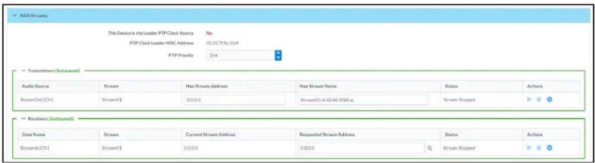
- Device is Master PTP Clock Source indicates whether the DM NAX device's PTP clock is the master clock on the network. Yes will be displayed in green when the local DM-NAX-AUD-IO's clock is the PTP master clock and No will be displayed in red when another PTP clock on the network is operating as the master clock.
- Master Clock Status displays the Master Clock ID of the device on the network that is currently acting as the master clock.
- PTP Priority: This sets the priority of the local DM NAX device's PTP clock relative to other clocks on the network. The default setting is 254 (one increment higher than the lowest possible value) so that the DM-NAX-AUD-IO will only operate as clock master if no other PTP master is present on the network. Valid values range from 1 to 255.
Configure Transmitters
To configure the DM NAX transmit stream, do the following.
- Enter a valid multicast address in the NAX Stream Address field.
- Enter a name in the NAX Stream Name field by which the stream can be identified. This stream name is associated with the DM NAX stream's multicast address by other DM NAX or AES67 devices, like a device hostname that resolves to a given IP address.
- Status indicates whether a stream is transmitting or not. When the stream has started or stopped, the Status column will update accordingly.
- Click the configure button (⚙️) in the Actions column. The Configure dialog appears:

-
Set the Auto Initiation toggle to the right position to enable auto initiation. Set the toggle to the left position to disable auto initiation.
-
If Auto Initiation is enabled for a given stream, the stream will begin transmitting automatically and will be available as a multicast stream on your network at the specified multicast address.
-
If Auto Initiation is disabled for the input, the stream will not begin transmitting until it is manually initiated.
-
To set the port number, do one of the following:
-
Click the arrows to increase or decrease the port number by increments of 1.
-
Manually enter a port number in the Port field. The default port number for DM NAX streams is 5004.
-
Click OK to save or click Cancel to cancel the changes.
Configure Receivers
-
Enter the multicast address of a transmitting stream in the Requested Stream Address field to subscribe the receiver to the stream.
-
Click the configure button (💡) in the Actions column. The Configure dialog appears:
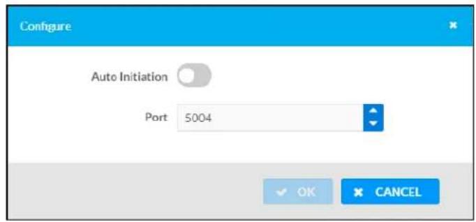
-
Set the Auto Initiation toggle to the right position to enable auto initiation. Set the toggle to the left position to disable auto initiation.
-
If Auto Initiation is enabled, the stream will begin automatically when the receiver subscribes to the transmitter.
-
If Auto Initiation is disabled, the stream will not begin until it is manually initiated.
-
To set the port number, do one of the following:
-
Click the arrows to increase or decrease the port number by increments of 1.
-
Manually enter a port number in the Port field. The default port number is 5004.
-
Click OK to save or click Cancel to cancel the changes.
Mixing
The Mixing matrix is used to route a local input or AES67 stream to an output on the DM-NAX-AUD-IO.
NOTE: To receive an AES67 stream from Dante devices, see OLH 1001151.
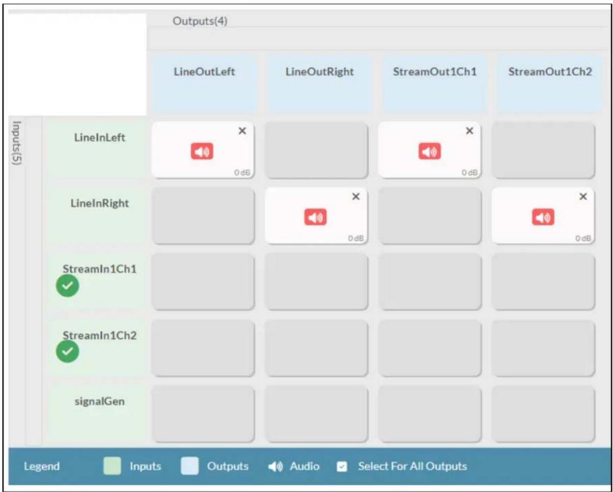
other
| Inputs(S) | LineOutLeft | LineOutRight | StreamOut1Ch1 | StreamOut1Ch2 | |---|---|---|---|---| | LineInLeft | 0 dB | | 0 dB | | | LineInRight | | 0 dB | | 0 dB | | StreamIn1Ch1 | | | | | | StreamIn1Ch2 | | | | | | signalGen | | | | |To route inputs to outputs on the device:
- Click the cells corresponding to the desired output that are to be paired for routing. Once a route is made, appears. The input that you have selected for a given row will route to the output corresponding to that row in the matrix.
• To break a given route click or✗
Each output can have any number of inputs routed to it. To adjust the mix setting for a route, click the dB value of the cell, then do one of the following:
- Move the slider up to increase or down to decrease the mix level.
- Click the arrows to increase or decrease the mix level.
- Manually enter a value in the field.

Residential Mode
This section provides the following information:
• System Setup on page 501
• Commissioning on page 505
• Output Channels on page 506
- Inputs on page 513
• NAX Streams on page 514
- Routing on page 517
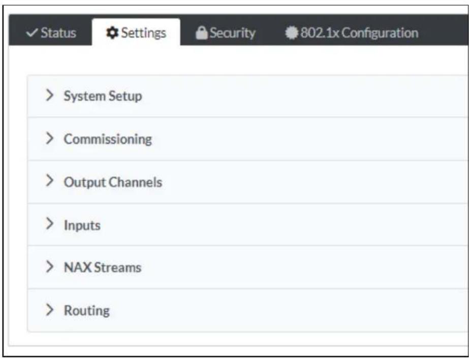
System Setup
The System Setup section displays information about the Date/Time, Auto Update, Network, Control System, Cloud Settings, and Device Modes.
Date/Time
Use the Date/Time section to configure the date and time settings of the DM-NAX-AUD-IO.
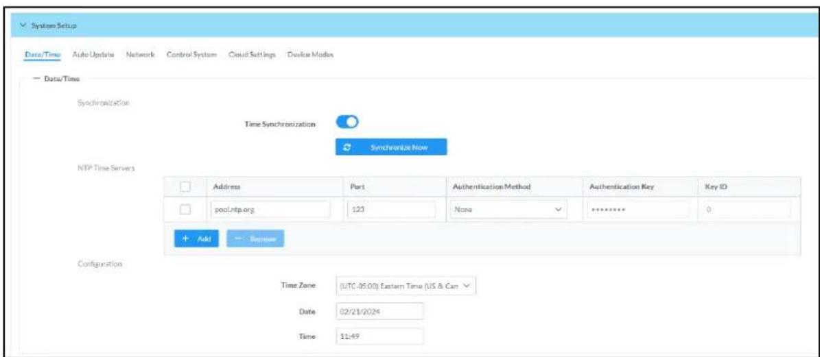
Time Synchronization
-
Set the Time Synchronization toggle to the right position to enable or left position to disable time synchronization. By default, time synchronization is enabled.
-
In the NTP Time Servers table, enter the URL of a NTP (Network Time Protocol) or SNTP (Simple Network Time Protocol) server. Up to three time servers can be added on a device.
- Click Synchronize Now to perform time synchronization between the device's internal clock and the time server.
Time Configuration
- Click on the Time Zone drop-down menu to select the applicable time zone.
- In the Date field, enter the current date.
- In the Time (24hr Format) field, enter the current time in 24-hour format.
Click the Save Changes button to save the settings.
Click Revert from the Actions drop-down menu to revert to the previous settings without saving.
Auto Update
The DM-NAX-AUD-IO can automatically check for and install firmware updates at scheduled intervals via the Auto Update feature.
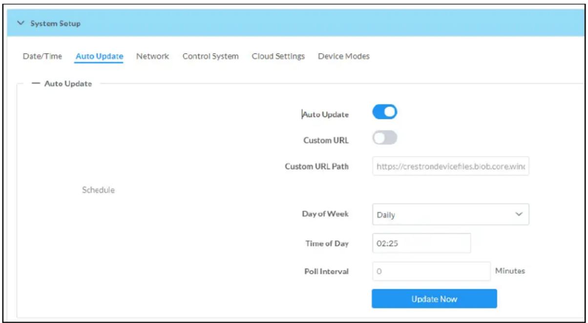
- Set the Auto Update toggle to the right position to enable Auto Update.
- Define the URL to download the updates by doing either of the following:
a. Use the default URL to download the updates from the Crestron server.
b. Use a custom URL. Set the Custom URL toggle to the right position to enable a custom URL. In the Custom URL Path text box, enter the path to a custom manifest file in the F or SFTP URL format. Use the Crestron Auto Update Tool to generate a custom manifest file, then store the file on an FTP (File Transfer Protocol) or SFTP (Secure File Transfer Protocol) server.
- Set a schedule for the automatic firmware update by doing either of the following:
a. Select the desired Day of Week and Time of Day (24-hour format) values.
b. Set the Poll Interval by entering a value from 60 to 65535 minutes. A value of 0 disables the Poll Interval.
4. Click Save Changes.
Clicking Update Now causes the device to check for a firmware update immediately. If a schedule was set in step 4 above, that schedule still remains in effect.
Network
The Network section contains network-related settings for the DM-NAX-AUD-IO, including the Hostname, Domain, Primary Static DNS, and Secondary Static DNS.
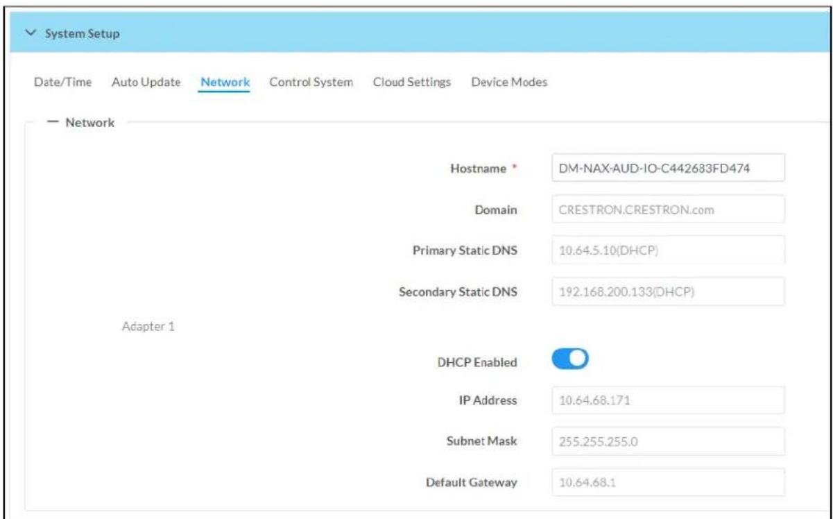
NOTE: By default, the host name of the DM-NAX-AUD-IO consists of the model name followed by the MAC address of the device. For example, DM-NAX-AUD-IO-00107FB58088.
Adapter 1
The Adapter 1 subheading contains settings for DHCP, IP Address, Subnet Mask, and Default Gateway of Ethernet adapter 1 on the rear panel of the device.
NOTE: DM NAX devices' internal processes use IP addresses in the 10x10 range. This IP range should be avoided when addressing DM NAX devices to prevent conflicts.
Set the DHCP toggle to enabled (right) or disabled (left) to specify whether the IP address of the DM-NAX-AUD-IO is to be assigned by a DHCP (Dynamic Host Configuration Protocol) server.
- Enabled: When DHCP is enabled (default setting), the IP address of the DM-NAX-AUD-IO is automatically assigned by a DHCP server on the local area network (LAN).
- Disabled: When DHCP is disabled, manually enter information in the following fields:
Primary Static DNS: Enter a primary DNS IP address.
Secondary Static DNS: Enter a secondary DNS IP address.
IP Address: Enter a unique IP address for the DM-NAX-AUD-IO.
- Subnet Mask: Enter the subnet mask that is set on the network.
Default Gateway: Enter the IP address that is to be used as the network's gateway.
To save any new network entries, click Save Changes.
Control System

- Click the Encrypt Connection button to navigate to the Security tab to configure encryption settings.
- Enter the username in the Control System Username field.
- Enter the password in the Control System Password field.
- Enter the Room ID in the Room ID field.
- Enter the IP ID of the DM-NAX-AUD-IO in the IP ID field.
- Enter the IP address or hostname of the control system in the IP Address/Hostname field.
- Click the Save Changes button to save the new entries. The Control System Save message box appears, indicating that the control system settings were saved successfully. Click the Revert button to revert to the previous settings without saving.
Cloud Settings

Set the Cloud Settings toggle to enabled (right) or disabled (left) to specify whether the DM-NAX-AUD-IO can communicate with the XiO Cloud® platform.
Device Modes
Use the Device Modes section to configure the Application Mode.

- Application Mode: The Application Mode determines which options and controls are available.
Select Residential (Standard) or Commercial (Advanced). A Reboot confirmation message box appears.
- Click Yes, Reboot Now to reboot the device into the selected mode. The Reboot message box appears.
- Wait for the device reboot to complete before attempting to reconnect to the device.
Commissioning
The Commissioning section provides a quick way to automatically assign multicast addresses to the device's internal audio-over-IP stream transmitters.

Click Assign Addresses to give each DM NAX transmitter in the DM-NAX-AUD-IO a unique multicast address beginning with the specified Starting Multicast Address. The valid range for Starting Multicast Address is 239.8.0.0 to 239.127.255.254.
NOTE: This will begin transmitting multicast traffic on your network, refer to the General Network Requirements document for details.
Output Channels
The Zones section contains the Volume and Mute settings for all zone outputs of the device, as well as a Configure option for more advanced settings within each zone.

Give each zone a friendly name using the Name column of the Zones table. If the device is paired with a control system, these names may be overwritten by the control system's program.
To configure the zone volume, do one of the following:
- Move the Volume slider to the right to increase or to the left to decrease the zone volume.
- Click the % arrows to increase or decrease the zone volume. Values range from 0 to 100%, adjustable in increments of 1%.
- Manually enter a value in the Volume field.
To mute all audio output from a zone, click its respective Mute button. To unmute the zone, click the Muted button.
Zone Settings
To configure zone settings, click the Configure button (Configure). The Edit Zone window appears.
Zone
Click Zone to access the settings for Tone, Balance, and Delay.
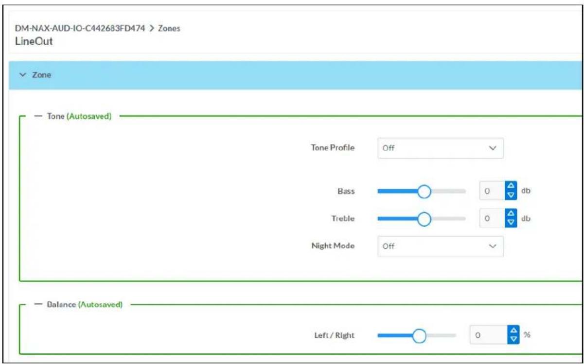
The Tone section provides adjustments for the Tone Profile, Bass, Treble, Loudness, and Night Mode settings of the zone output.
NOTE: The Tone Profile, Bass, Treble, and Loudness settings in the Tone section are all applied separately from the Equalizer Settings for the zone. This means that any adjustments made in the Tone section will stack with those made in the Equalizer Settings section.
- To select a tone profile preset for the zone, select an option from the Tone Profile drop-down menu. The available options are Off, Classical, Jazz, Pop, Rock, and Spoken Word. By default, Off is selected.
-
Bass: To adjust the bass, do one of the following:
-
Move the Bass slider to the right to increase or to the left to decrease the bass.
- Click the db arrows to increase or decrease the db. Values range from -12 db to 12 db, adjustable in increments of 1 db.
-
Manually enter a value in the Bass field.
-
Treble: To adjust the treble, do one of the following:
-
Move the Treble slider to the right to increase or to the left to decrease the treble.
- Click the db arrows to increase or decrease the db. Values range from -12 db to 12 db, adjustable in increments of 1 db.
-
Manually enter a value in the Treble field.
-
To enable the loudness setting on the zone output, slide the Loudness switch to the right. To disable loudness, slide the Loudness switch to the left.
-
The Night Mode feature applies subtle processing to restrict the dynamic range of the zone audio, to allow for lower listening levels at night or in rooms where higher listening levels would be disruptive. To select a dynamics processing level, select an option from the Night Mode drop-down menu. The available options are Off, Low, Medium, and High. By default, Off is selected.
Balance
To adjust the left/right balance of the stereo output signal, do one of the following:
- Move the Balance slider to the right to shift the stereo balance to the right channel or to the left to shift the balance to the left.
- Click the arrows to adjust the balance left or right. The up arrow shifts the balance to the right while the down arrow shifts the balance to the left.
- Manually enter a value in the Balance field. Values range from -50 to 50, adjustable in increments of 1. Positive values shift the balance to the right while negative values shift the balance to the left.
Delay
To set the delay, do one of the following:
- Move the Delay Time(ms) slider to the right to increase or to the left to decrease the delay time.
- Click the ms arrows to increase or decrease the delay. Values range from 0 ms to 85 ms, adjustable in increments of 1 ms.
- Manually enter a value in the Delay Time(ms) field.
Output
Click Output to access the settings for Minimum/Maximum Volume, Stereo/Mono, Signal, Bussing Volume Offset, Signal Generator, and Equalizer Settings.
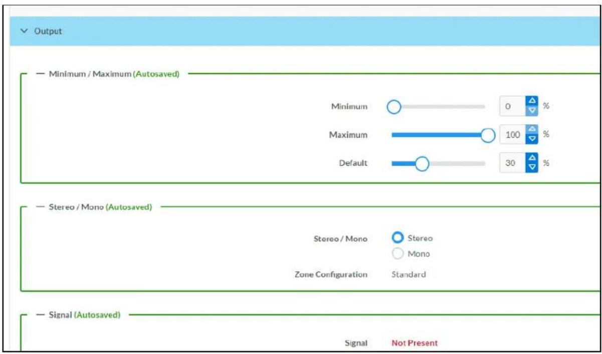
Minimum/Maximum Volume

-
To set the minimum volume of the zone, do one of the following:
-
Move the Minimum slider to the right to increase or to the left to decrease the minimum volume.
- Click the % arrows to increase or decrease the minimum volume. Values range from 0 to 50%, adjustable in increments of 1%.
-
Manually enter a value in the Minimum field.
-
To set the maximum volume of the zone, do one of the following:
-
Move the Maximum slider to the right to increase or to the left to decrease the maximum volume.
- Click the % arrows to increase or decrease the maximum volume. Values range from 70 to 100%, adjustable in increments of 1%.
- Manually enter a value in the Maximum field.
NOTE: When a Minimum and Maximum volume are set, the 1-100% range represented by the Zone and Default volume controls are scaled to the range set. For example, if a Minimum of 10% and a Maximum of 80% are set for a zone, the 1-100% range of the Zone volume control is scaled to the 10%-80% range set as the Minimum and Maximum.
-
To set the default volume of the zone, do one of the following:
-
Move the Default slider to the right to increase or to the left to decrease the default volume.
- Click the % arrows to increase or decrease the default volume. Values range from 0 to 50% adjustable in increments of 1%.
- Manually enter a value in the Default field.
NOTE: The Default volume is applied as the Zone volume any time the zone receives a source route and no source was previously routed to that zone.
Stereo/Mono

Select either Stereo or Mono from the Stereo/Mono radio buttons. If Stereo is selected, both output channels can have independent audio content. If Mono is selected, both output channels receive the same audio content.
Signal

The Signal section is a read-only field that displays the Signal and Clipping status of the zone output.
- If an output signal is present but not clipping, Signal will display Present in green and Clipping will display None in green.
- If an output signal is present and clipping, Signal will display Present in green and Clipping will display Present in red.
- If no output signal is detected, Signal will display Not Present in red and Clipping will display None in green.
Bussing Volume Offset

Bussing Volume Offset is an additional level compensation applied to the zone relative to any other zones it is grouped with via the Bussing feature.
To set the bussing volume offset, do one of the following:
- Move the Bussing Volume Offset slider to the right to increase or to the left to decrease the offset.
- Click the db arrows to increase or decrease the offset. Values range from -12 dB to 12 dB, adjustable in increments of 1 dB.
- Manually enter a value in the Bussing Volume Offset field.
Signal Generator

The DM-NAX-AUD-IO has a built-in signal generator that allows an integrator to send an audio signal to the output for testing purposes.
-
To route the signal generator to the zone output, click the Signal Generator button so that it displays Active and is highlighted in blue. To unroute the signal generator on the zone output, click the Signal Generator button so that it displays Inactive and is highlighted in grey. By default, the signal generator is not routed to the zone output.
-
To adjust the signal generator's volume, do one of the following:
-
Move the Signal Generator Volume slider right to increase or left to decrease the volume.
- Click the arrows to increase or decrease the signal generator volume. Values range from 0 to 100, adjustable in increments of 1.
- Manually enter a value in the Signal Generator Volume field.
Equalizer Settings
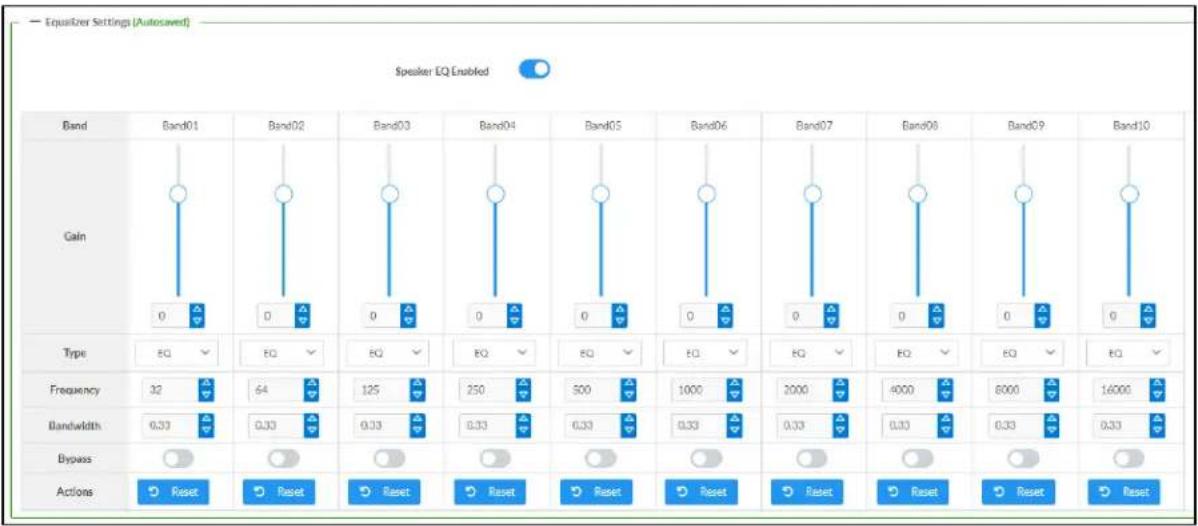
bar
| Band | Gain | Frequency | Bandwidth | Bypass | Actions | |--------|------|-----------|------------|---------|---------| | Band01 | 0 | 32 | 0.33 | | Reset | | Band02 | 0 | 64 | 0.33 | | Reset | | Band03 | 0 | 125 | 0.33 | | Reset | | Band04 | 0 | 250 | 0.33 | | Reset | | Band05 | 0 | 500 | 0.33 | | Reset | | Band06 | 0 | 1000 | 0.33 | | Reset | | Band07 | 0 | 2000 | 0.33 | | Reset | | Band08 | 0 | 4000 | 0.33 | | Reset | | Band09 | 0 | 8000 | 0.33 | | Reset | | Band10 | 0 | 16000 | 0.33 | | Reset |The zone output of the DM-NAX-AUD-IO has a dedicated ten-band equalizer that can be fully customized to tune the zone output signal to the needs of an install. Each band can have a discrete ga filter type, center frequency, and bandwidth set, and can also be bypassed. The equalizer itself can also be bypassed using the Speaker EQ Enabled toggle.
- Set the Speaker EQ Enabled toggle to the right position to enable the equalizer. Set the toggle to the left position to bypass the equalizer.
NOTE: When Speaker EQ Enabled is disabled, all equalizer bands are bypassed. This is a quick way to perform A/B testing of the entire EQ curve.
- With the Speaker EQ Enabled toggle in the right position, do the following to configure a given equalizer band:
a. To set a band's gain, do one of the following:
- Move the Gain slider up to increase or down to decrease the gain.
- Click the arrows to increase or decrease the gain. Values range from -40 dB to 20 dB, adjustable in increments of 0.1 dB.
- Manually enter a value in the Gain field.
b. Select a filter type from the Type drop-down menu. By default, all bands are set to the EQ filter type. Some filter types will disable other settings in their respective band while enabled. For example, selecting the LowPass filter type for a band will disable that band's Gain and Bandwidth settings, since the LowPass filter applies a fixed roll-off slope at a set frequency. The available filter types are:
- EQ: a fully parametric filter that can boost or cut a range of frequencies.
- Notch: a parametric filter designed to more precisely cut a frequency or range of frequencies. A notch filter can achieve a narrower bandwidth than the standard EQ parametric filter type.
- TrebleShelf: a filter that boosts or cuts all frequencies above a set frequency by a set gain.
- BassShelf: a filter that boosts or cuts all frequencies below a set frequency by a set gain.
- LowPass: a filter that fully cuts all frequencies above a set frequency using a fixed roll-off slope of -12 dB per octave.
- HighPass: a filter that fully cuts all frequencies below a set frequency using a fixed roll-off slope of -12 dB per octave.
c. Set a center frequency for the equalizer band to tune a specific portion of the audible frequency spectrum. To set the center frequency, do one of the following:
- Click the arrows to increase or decrease the frequency. Values range from 20 Hz to 20 kHz, adjustable in increments of 1 Hz. Each band has a default center frequency that will be applied if the Reset button at the bottom of the band is clicked.
- Manually enter a value in the Frequency field.
d. Set a bandwidth to determine how wide of a frequency range is effected by the equalizer band. To set the bandwidth, do one of the following:
- Click the arrows to increase or decrease the bandwidth. Values range from 0.1 octaves to 4.0 octaves, adjustable in increments of 0.1 octave.
- Manually enter a value in the Bandwidth field.
e. The individual Bypass controls allow you to bypass a single band of equalization at a time for more granular A/B testing of a single filter. Set a band's Bypass toggle to the right position to bypass that band. Set the toggle to the left position to disable the bypass. By default, Bypass is disabled.
f. Each equalizer band has a Reset button that will reapply the default settings for that band.
Click Done to return to the Settings tab of the web user interface.
Inputs
The Inputs section is used to configure the Name, Compensation, and Mute attributes of the available analog, digital, and media streaming inputs on the DM-NAX-AUD-IO.

Configure Inputs
-
If needed, enter a friendly name for each input in its Name field.
-
To set a level compensation adjustment for a given input, do one of the following:
-
Move the Compensation slider up to increase or down to decrease the level compensation. Compensation increases or decreases the level of the incoming audio signal on any of the physical inputs on the device's rear panel.
- Click the db arrows to increase or decrease the compensation. Values range from -10 dB to 10 dB, adjustable in increments of 1 dB.
-
Manually enter a value in the Compensation field.
-
To mute the signal from the corresponding input, set the Mute toggle to the right. To disable the mute, set the Mute toggle to the left. By default, Mute is disabled.
Monitor the device's input signals using the text indicators in the Signal Present and Clipping Detected columns:
• Signal Presence indicates whether or not a signal is detected in that zone.
- Clipping Detected indicates if the signal is Clipping or Nominal (non-clipping).
NAX Streams
The two local line level input channels of the DM-NAX-AUD-IO can be made available as a DM NAX audio-over-IP stream.
Click NAX Streams to expand the tab and display the following information.

- Device is Master PTP Clock Source indicates whether the device is the master for PTP on the network. Yes will be displayed in green when the local DM-NAX-AUD-IO is the PTP clock master and No will be displayed in red when another PTP clock on the network is operating as the master clock.
- Master Clock Status displays the Master Clock ID of the device on the network that acts as the Master Clock.
- PTP Priority: This sets the priority of the local DM NAX device's PTP clock relative to other clocks on the network. The default setting is 254 (one increment higher than the lowest possible value) so that the DM-NAX-AUD-IO will only operate as clock master if no other PTP master is present on the network. Valid values range from 1 to 255.
Configure Transmitters
To configure a DM NAX transmit stream, do the following.
- Enter a valid multicast address in the NAX Stream Address field.
- Enter a name in the NAX Stream Name field by which the stream can be identified. This stream name is associated with the DM NAX stream's multicast address by other DM NAX or AES67 devices, like a device hostname that resolves to a given IP address.
- Status indicates whether a stream is transmitting or not. When the stream has started or stopped, the Status column will update accordingly.
- Click the configure button (💡) in the Actions column. The Configure dialog appears:

-
Set the Auto Initiation toggle to the right position to enable auto initiation. Set the toggle to the left position to disable auto initiation.
-
If Auto Initiation is enabled for a given stream, the stream will begin transmitting automatically and will be available as a multicast stream on your network at the specified multicast address.
-
If Auto Initiation is disabled for the input, the stream will not begin transmitting until it is manually initiated.
-
To set the port number, do one of the following:
-
Click the arrows to increase or decrease the port number by increments of 1.
-
Manually enter a port number in the Port field. The default port number for DM NAX streams is 5004.
-
Click OK to save or click Cancel to cancel the changes.
Configure Receivers
- Enter the multicast address of a transmitting stream in the Requested Stream Address field to subscribe the receiver to the stream.
- Click the configure button (💡) in the Actions column. The Configure dialog appears:
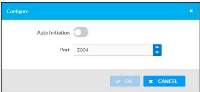
-
Set the Auto Initiation toggle to the right position to enable auto initiation. Set the toggle to the left position to disable auto initiation.
-
If Auto Initiation is enabled, the stream will begin automatically when the receiver subscribes to the transmitter.
-
If Auto Initiation is disabled, the stream will not begin until it is manually initiated.
-
To set the port number, do one of the following:
-
Click the arrows to increase or decrease the port number by increments of 1.
-
Manually enter a port number in the Port field. The default port number is 5004.
-
Click OK to save or click Cancel to cancel the changes.
Routing
The Routing section is used to route a local input or AES67 stream to a Zone on the DM-NAX-AUD-IO.
NOTE: To receive an AES67 stream from Dante devices, see OLH 1001151.

To route an input to a zone, click the box in the routing matrix where the zone's row overlaps the corresponding input's column. Once a route is made, appears. To break a given route click or . To route a single input to all zones, click on the icon under the input's name.
Security
Click the Security tab to configure security for users and groups and to allow different levels of access to the DM-NAX-AUD-IO functions. By default, security is disabled.

Select Encrypt and Validate, Encrypt, or OFF in the SSL Mode drop-down menu, to specify whether to use encryption. By default, SSL Mode is set to OFF.
Current User
Click the Current User tab to view read-only information or to change the password for the current user.

-
Click the Change Current User Password button to provide a new password for the current user.
-
In the Change Password dialog, enter the current password in the Current Password field, the new password in the Password field, and then re-enter the same new password in the Confirm Password field.
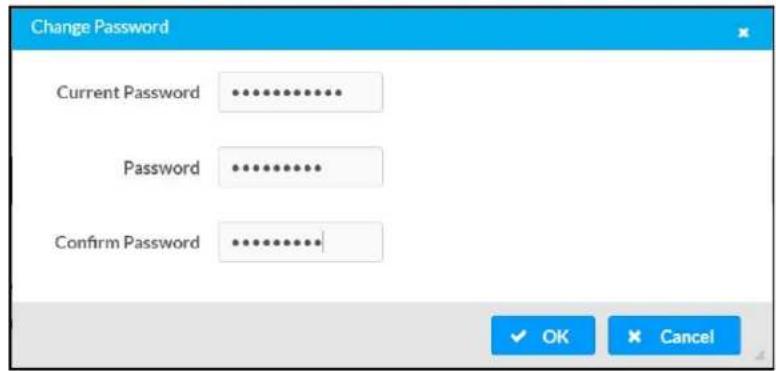
- Click OK to save or click Cancel to cancel the changes.
Users
Click the Users tab to view and edit user settings. The Users tab can be used to add or remove local and Active Directory users and preview information about users.
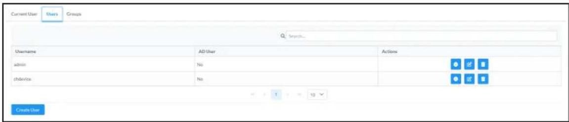
Use the Search Users field to enter search term(s) and display users that match the search criteria.
If users listed in the Users table span across multiple pages, navigate through the list of users by clicking a page number or by using the left or right arrows at the bottom of the Users pane to move forward or backward through the pages.
Each page can be set to display 5, 10, or 20 users by using the drop-down menu to the right of the navigation arrows.
Information about existing users is displayed in table format and the following details are provided for each user.
- Username: Displays the name of the user.
- AD User: Displays whether the user requires authentication using Active Directory.
Click the corresponding button in the Actions column to view detailed user information or to delete the user.
To create a new user, click the Create User button.
Create a New Local User
-
Click the Create User button in the User tab.
-
In the Create User dialog, enter the following:

a. Enter a user name in the Name field. A valid user name can consist of alphanumeric characters (letters a-z, A-Z, numbers 0-9) and the underscore "_" character.
b. Enter a password in the Password field; re-enter the same password in the Confirm Password field.
c. Assign the access level by selecting one or more groups from the Groups drop-down list.
NOTE: Make sure that the Active Directory User toggle is disabled.
- Click OK to save or click Cancel to cancel the changes.
Add an Active Directory User
Users cannot be created or removed from the Active Directory server, but access can be granted to an existing user in the Active Directory server.
To grant access to an Active Directory user, you can either add the user to a local group on the DM-NAX-AUD-IO, or add the Active Directory group(s) that they are a member of to the DM-NAX-AUD-IO.
To add an Active Directory user.
- Click the Create User button.
- In the Create User dialog, enter the following.
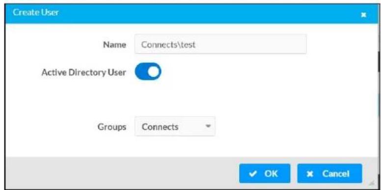
a. Enter a user name in the Name field in the format "Domain\UserName", for example "crestronlabs.com\JohnSmith". Valid user names can contain alphanumeric characters (letters a-z, A-Z, numbers 0-9) and the underscore "_" character.
b. Select one or more groups from the Groups drop-down list.
NOTE: Make sure that the Active Directory User toggle is set to enabled.
- Click OK to save or click Cancel to cancel the changes.
Delete User
Click the trashcan button (☐) in the Actions column to delete the user. Click Yes when prompted to delete the user or No to cancel the deletion.
After a user is removed from a group, they lose any access rights associated with that group. Note that the user account is not deleted by the delete user operation.
View User Details
Click the information button (0) in the Actions column to view information for the selected user. The User Details dialog displays the following information for the selected user.
- Name: Displays the name of the selected user.
• Active Directory User: Displays whether the user is an Active Directory user. - Group: Displays group(s) the selected user is part of.

Click OK to close the User Details dialog and to return to the Users tab.
Update User Details

- Click the edit button() in the Actions column to update information for the selected user.
- Enter a password in the Password field; re-enter the same password in the Confirm Password field.
- Select one or more groups to assign the user to from the Groups drop-down list.
- Click OK to save or click Cancel to cancel the changes.
The Update User dialog also displays the following read-only information for the selected user.
• Name: Displays the name of the user.
• Active Directory User: Displays whether the user is an Active Directory user.
Groups
Click the Groups tab to view and edit group settings. The Groups tab can be used to add local and Active Directory groups, remove local and Active Directory groups, and preview information about a group.
Use the Search Groups field to enter search term(s) and display groups that match the search criteria.
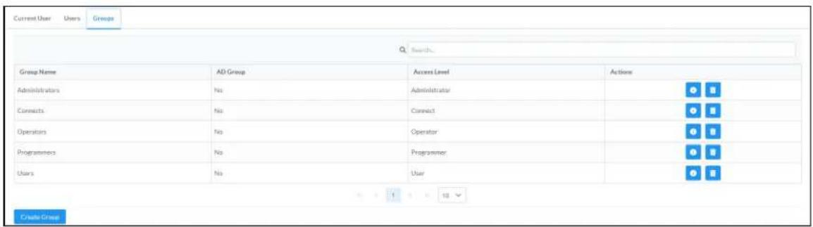
If groups listed in the Groups table span across multiple pages, navigate through the groups by clicking a page number or by using the left or right arrows at the bottom of the Groups pane to move forward or backward through the pages.
Additionally, each page can be set to display 5, 10, or 20 groups by using the drop-down menu to the right of the navigation arrows.
Existing groups are displayed in a table and the following information is provided for each group:
- Group Name: Displays the name of the group.
• AD Group: Displays whether the group requires authentication using Active Directory. - Access Level: Displays the predefined access level assigned to the group (Administrator, Programmer, Operator, User, or Connect).
Click the corresponding button in the Actions column to view detailed group information (☐) or to delete ☐ selected group.
Click on the Create Group button in the Groups tab to create new group.
Create Local Group

- Click the Create Group button.
- In the Create Group dialog, enter the following:
a. Enter the group name in the Name field.
b. Assign the group access level by selecting a predefined access level (Administrator, Connect, Operator, Programmer, User) from the Access Level drop-down list.
NOTE: Make sure that the Active Directory Group toggle is disabled.
- Click OK to save. Click Cancel to cancel the changes.
Add Active Directory Group
A group cannot be created or removed from the Active Directory server, but access can be granted to a existing group in Active Directory.

Once the group is added, all members of that group will have access to the DM-NAX-AUD-IO.
- Click the Create Group button.
- In the Create Group dialog enter the following:
a. Enter the group name in the Name field, for example "Engineering Group". Note that group names are case sensitive; a space is a valid character that can be used in group names.
- Assign the group access level by selecting a predefined access level (Administrator, Connect, Operator, Programmer, User) from the Access Level drop-down list.
NOTE: Make sure that the Active Directory Group toggle is enabled.
- Click OK to save. Click Cancel to cancel the changes.
Delete a Group
Click the trashcan button (☐) in the Actions column to delete a group. Click Yes when prompted to delete the group or No to cancel the deletion.
When a group is deleted, users in the group are not removed from the device or Active Directory server. However, because a user's access level is inherited from a group(s), users within the deleted group will lose access rights associated with the group.
View Group Details
Click the information button (6) in the Actions column to view information for the selected group. The Group Details dialog lists the following information for the selected group.

• Name: Displays the name of the group.
- Access Level: Displays the access level of the group and its users.
• Active Directory Group: Displays whether the group is an Active Directory group.
Click OK to close the Group Details dialog and to return to the Groups tab.
802.1x Configuration
The DM-NAX-AUD-IO has built-in support for the 802.1X standard (an IEEE network standard designed to enhance the security of wireless and Ethernet LANs. The standard relies on the exchange of messages between the device and the network's host, or authentication server), allowing communication with the authentication server and access to protected corporate networks.
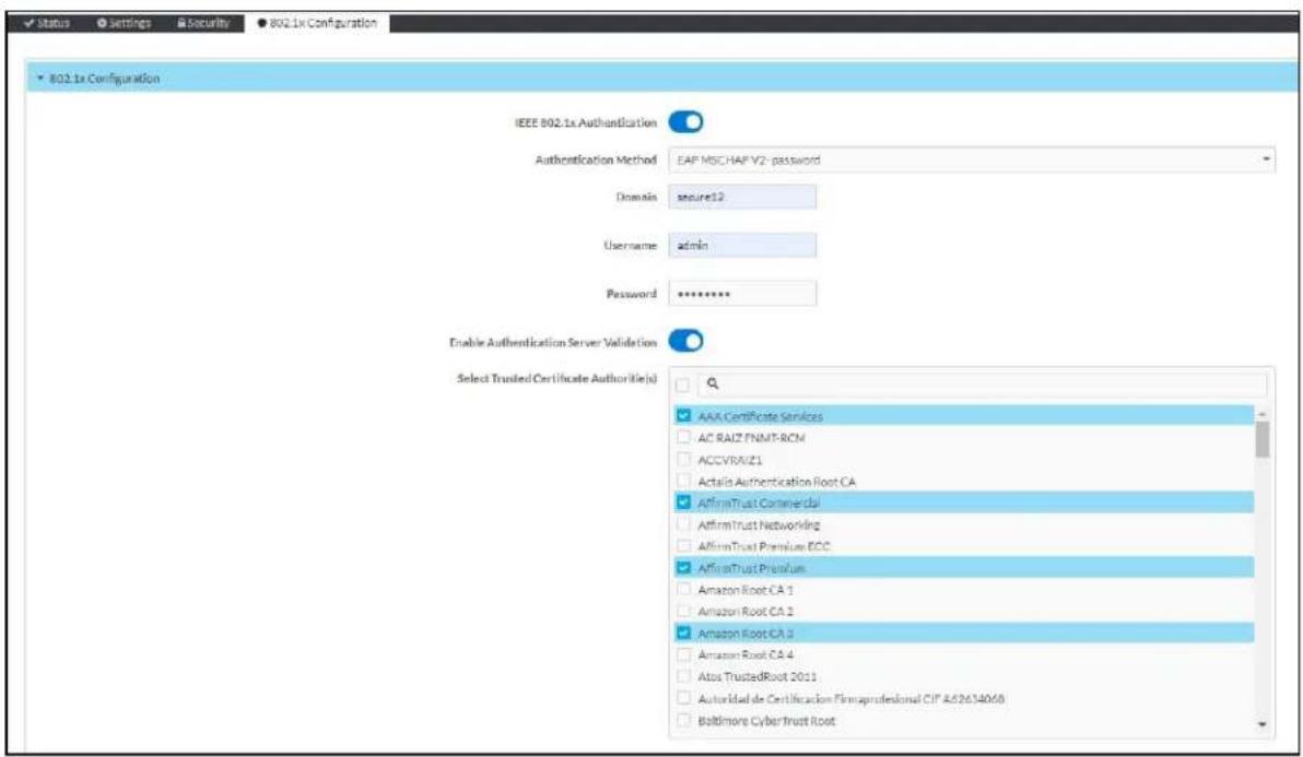
To Configure DM-NAX-AUD-IO for 802.1X Authentication
-
Set the IEEE 802.1X Authentication toggle to enabled. This will enable all options on the 802.1X dialog.
-
Select the Authentication method: EAP-TLS Certificate or EAP-MSCHAP V2 Password according to the network administrator's requirement.
-
Do either one of the following:
- Select EAP-TLS Certificate, click Action/Manage Certificates to upload the required machine certificate. The machine certificate is an encrypted file that will be supplied by the network administrator, along with the certificate password.
- Select EAP-MSCHAP V2 Password, enter the username and password supplied by the network administrator into the Username and Password fields. This method does not require the use of a machine certificate, only the user name and password credentials.
- If you enabled the Enable Authentication Server Validation option, this will enable the Select Trusted Certificate Authoritie(s) list box which contains signed Trusted Certificate Authorities (CAs) preloaded into the DM-NAX-AUD-IO.
Select the check box next to each CA whose certificate can be used for server validation, as specified by the network administrator.
If the network does not use any of the listed certificates, the network administrator must provide a certificate, which must be uploaded manually via the Manage Certificates functionality.
-
If required, type the domain name of the network in the Domain field.
-
When the 802.1X settings are configured as desired, click Save Changes to save the changes to the device and reboot it. Click Revert to cancel any changes.
Access the Web Interface With the Crestron Toolbox Application
To access the web interface by opening a web browser within the Crestron Toolbox™ application, do the following:
-
Open the Crestron Toolbox application.
-
From the Tools menu, select Device Discovery Tool. You can also access the Device Discovery Tool by clicking the Device Discovery Tool button ( ) in the Crestron Toolbox toolbar. The DM-NAX-AUD-IO is discovered and listed in the device list on the left side of the screen. The associated host name, IP address, and firmware version are also displayed.
NOTE: If there is security software running on the computer, a security alert might be displayed when the Crestron Toolbox application attempts to connect to the network. Make sure to allow the connection, so that the Device Discovery Tool can be used.
-
In the Device Discovery Tool list, double-click your device.
-
Enter your credentials in the Authentication Required dialog that opens, and then click Log In.
-
Click the Web Configuration button in the Configuration page displayed on the left side of the Device Discovery Tool.
DM-NAX-AUD-USB
This section describes how to configure the DM-NAX-AUD-USB.
Web Interface Configuration
The DM-NAX-2XLRI-1G web interface allows you to view status information and configure network and device settings.
Access the Web Interface
To access the web interface, do either of the following:
- Access the Web Interface with a Web Browser on page 530
- Access the Web Interface With the Crestron Toolbox™ Application on page 584
The web interface is accessed from a web browser. The following table lists operating systems and their corresponding supported web browsers.
Operating System and Supported Web Browsers
| OPERATING SYSTEM SUPPORTED WEB BROWSERS | |
| Windows® operating system | ChromeTM web browser, version 31 and laterFirefox® web browser, version 31 and laterInternet Explorer web browser, version 11 and laterMicrosoft Edge web browser |
| macOS® operating system | Safari® web browser, version 6 and laterChrome web browser, version 31 and laterFirefox web browser, version 31 and later |
Access the Web Interface with a Web Browser
- Enter the IP address of the DM-NAX-AUD-USB into a web browser.
NOTE: To obtain the IP address, use the Device Discovery Tool option in Crestron Toolbox™ application or an IP scanner application.
- If you are creating a user account for the first time, do the following; otherwise, skip to step 3.
a. Enter a username in the Username field.
b. Enter a password in the Password field.
c. Re-enter the same password in the Confirm Password field.

d. Click Create User. The Device Administration page appears.
- Enter the username in the Username field.
- Enter the password in the Password field.
- Click Sign In.
Action
The Action drop-down menu is displayed at the top right side of the interface and provides quick access to common device functions:
- Save Changes
- Revert
- Reboot
- Restore
- Update Firmware
- Download Logs
- Manage Certificates
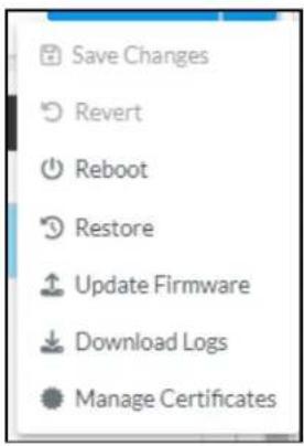
Save Changes
Click Save Changes to save any changes made to the configuration settings.
Revert
Click Revert to revert the device back to the last saved configuration settings.
Reboot the DM-NAX-AUD-USB
Certain changes to the settings may require the DM-NAX-AUD-USB to be rebooted to take effect. To reboot the device, do the following:
- Click Reboot in the Actions drop-down menu. The Confirmation message box appears.

- Click Yes, Reboot Now to reboot the device. The Reboot message box appears.
Wait for the device reboot to complete before attempting to reconnect to the device.
Restore to Factory Default Settings
- Click Restore in the Actions drop-down menu to restore the settings of the DM-NAX-AUD-USB to factory defaults.
NOTE: When settings are restored, all settings, including the network settings, will revert to the factory default. If a static IP address is set, restoring the device to factory default settings will revert the IP address to the default DHCP mode.

- Click Yes in the Confirmation dialog to restore the DM-NAX-AUD-USB to factory settings. Click No to cancel the restore operation.
A dialog is displayed again, indicating that the restore process was successful and that the device rebooted.
You can also restore to factory settings by pressing and holding the SETUP button on the rear panel of the device with power disconnected then connect the power supply and continue to hold SETUP button for 30 seconds.
Update Firmware
-
Click Update Firmware in the Actions drop-down menu.
-
In the Firmware Upgrade dialog, click + Browse.
-
Locate and select the desired firmware file, and then click Open. The selected firmware file name is displayed in the Firmware Upgrade dialog.
-
Click Load and wait for the progress bar to complete and for the OK button in the message to become clickable.
-
Click OK. The device with new firmware can now be accessed.
Download Logs
- Click Download Logs in the Actions drop-down menu to download the device message logs for diagnostic purposes.
The log file is downloaded to the Downloads folder of the PC.
Manage Certificates
Use the Manage Certificates dialog to add, remove, and manage certificates used in 802.1x and other protected networks.

-
Click Manage Certificates in the Actions drop-down menu. The following certificate tabs are displayed:
-
Root: The Root certificate is used by the DM-NAX-AUD-USB to validate the network's authentication server. The DM-NAX-AUD-USB has a variety of Root certificates, self-signed by trusted CAs (Certificate Authorities) preloaded into the device. Root certificates must be self-signed.
- Intermediate: The Intermediate store holds non self-signed certificates that are used to validate the authentication server. These certificates will be provided by the network administrator if the network does not use self-signed Root certificates.
- Machine: The machine certificate is an encrypted PFX file that is used by the authentication server to validate the identity of the DM-NAX-AUD-USB. The machine certificate will be provided by the network administrator, along with the certificate password. For 802.1x, only one machine certificate can reside on the device.
- Web Server: The Web Server certificate is a digital file that contains information about the identity of the web server.
To Add Certificates
- Click the corresponding certificate tab.
- Click the Add Root Certificate button.
- Click the + Browse button.
- Locate and select the file, and then click the Open button.
NOTE: If the certificate is a Machine Certificate, enter the password provided by the network administrator.
- Click OK. This will add the certificate to the list box, displaying the file name and expiration date.
The certificate is now available for selection and can be loaded to the device.
To Delete Certificates
- Click the corresponding certificate tab.
- Click the trashcan button ( ) in the Actions column to delete the certificate.
- Click Yes when prompted to delete the certificate or No to cancel the deletion.
Status
The Status tab is the first page displayed when opening the interface of the DM-NAX-AUD-USB. It displays general information about the DM-NAX-AUD-USB (such as Model Name, Firmware Version, and Serial Number), current network settings (such as Host Name and IP Address, etc.), and input and output ports' current status.
The Status tab can be accessed at any time by clicking the Status tab of the DM-NAX-AUD-USB interface.

Information displayed on the Status tab is organized into different sections.
Device
The Device section displays the Model, Firmware Version, and Serial Number of the DM-NAX-AUD-USB.

Click + More Details to review additional information about the DM-NAX-AUD-USB.
![— More Details DM-NAX-AUD-USB 1.0.0033.11191 Build Feb 13 2024(531246) Updater 1.0.0033.11191 Bootloader 1.00.00 CCUI Version 1.1327.1 XIOSDK 3.8.2 IoTSDK 1.11.0 Build time 11:19:07 Product ID 0x7A0A Revision ID 0x0100 HDCP2X-SKE HDCP2X-SKE HDCP2X-SKE [v9.0000.00000,#FFFFFFF] PRE-BOOT [v9.0000.00000] BOOTLOADER [v9.0000.00000] ctrl-audio-dsp-0 FW v11 [Driver v4.00] ctrl-extelkin-pps Driver v1.1 ctrl-prod-info Driver v3.0 PUF 1.0.0033.11191 EngDebug Mode True Forced Auth Mode True](/content/2026/05/985127/images/3468a77fa74e0f55f5ec4e576aeba68bcb7f70db7237c0e08554c7459bfa15fa.jpg)
Network
The Network section displays network-related information about the DM-NAX-AUD-USB, including the Hostname, Domain Name, and DNS Servers.
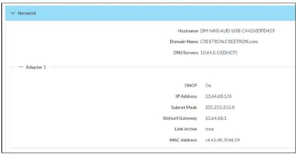
NOTE: By default, the host name of the DM-NAX-AUD-USB consists of the model name followed by the MAC address of the device. For example, DM-NAX-AUD-USB-00107FB58088.
Click + Adapter 1 to display an expanded section that shows additional information. If + Adapter 1 is selected, click - Less details to collapse the section.
Control System
The Control System section displays connection information, consisting of the following:
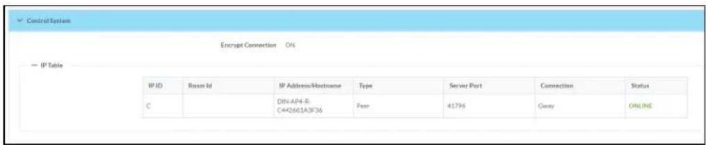
- Encrypt Connection: ON or OFF
• IP ID: Reports the currently used IP ID of the DM-NAX-AUD-USB - IP Address/Hostname: The IP address of the control system
• Room ID: Displays the room ID
• Status: OFFLINE or ONLINE
Settings
The Settings tab enables configuration of the DM-NAX-AUD-USB settings. The Settings page can be accessed at any time by clicking the Settings tab of the DM-NAX-AUD-USB interface.
Many options in the Settings tab are exclusive to a specific device mode: Residential or Commercial. The DM-NAX-AUD-USB is in Commercial mode by default.
This section provides the following information:
• Commercial Mode on page 538
• Residential Mode on page 556
Commercial Mode
The Settings tab enables you to configure the DM-NAX-AUD-USB settings. The Settings page can be accessed at any time by clicking the Settings tab of the DM-NAX-AUD-USB interface.

Settings available on the Settings page are organized into different sections.
System Setup
The System Setup section contains settings for Date/Time, Auto Update, Network, and Control System.
![System Setup Date/Time Auto Update Network Control System Cloud Settings Device Modes Data/Time Synchronization Time Synchronization Synchronize Now NTP Time Servers Address Port Authentication Method Authentication Key Key ID pool.ntp.org 123 None ******** 0 + Add - Runners Configuration Time Zone [UTC-05:00] Eastern Time (US & Can) Date 02/27/2024 Time 17:14](/content/2026/05/985127/images/b30594e83ddf74de8acf74d8634e2ea83a767cf51a226e90139c234bc01c7f64.jpg)
Date/Time
Use the Date/Time tab to configure the date and time settings of the DM-NAX-AUD-USB.
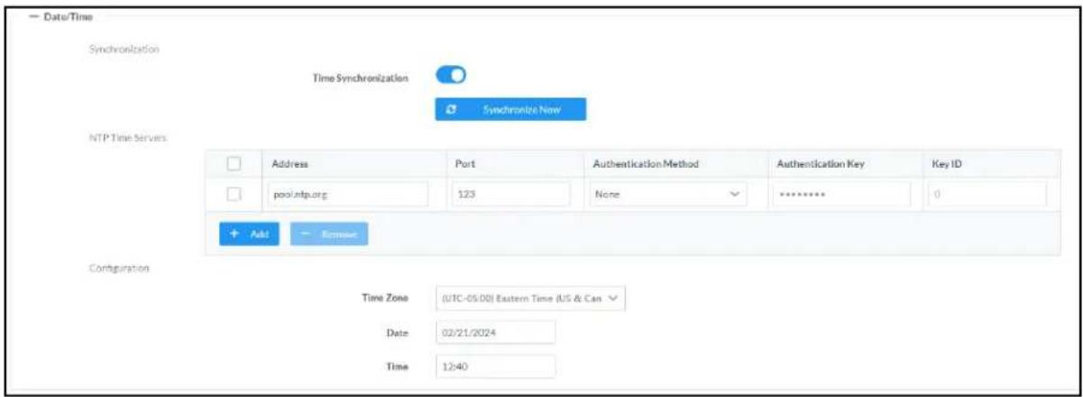
Time Synchronization
- Set the Time Synchronization toggle to the right position to enable or left position to disable time synchronization. By default, time synchronization is enabled.
- In the NTP Time Servers table, enter the URL of a NTP (Network Time Protocol) or SNTP (Simple Network Time Protocol) server. Up to three time servers can be added on a device.
- Click Synchronize Now to perform time synchronization between the device's internal clock and the time server.
Time Configuration
- Click on the Time Zone drop-down menu to select the applicable time zone.
- In the Date field, enter the current date.
- In the Time (24hr Format) field, enter the current time in 24-hour format.
Click the Save Changes button to save the settings.
Click Revert from the Actions drop-down menu to revert to the previous settings without saving.
Auto Update
The DM-NAX-AUD-USB can automatically check for and install firmware updates at scheduled intervals via the Auto Update feature.

-
Set the Auto Update toggle to the right position to enable Auto Update.
-
Define the URL to download the updates by doing either of the following:
a. Use the default URL to download the updates from the Crestron server.
b. Use a custom URL. Set the Custom URL toggle to the right position to enable a custom URL. In the Custom URL Path text box, enter the path to a custom manifest file in the F or SFTP URL format. Use the Crestron Auto Update Tool to generate a custom manifest file, then store the file on an FTP (File Transfer Protocol) or SFTP (Secure File Transfer Protocol) server.
- Set a schedule for the automatic firmware update by doing either of the following:
a. Select the desired Day of Week and Time of Day (24-hour format) values.
b. Set the Poll Interval by entering a value from 60 to 65535 minutes. A value of 0 disables the Poll Interval.
- Click Save Changes.
Clicking Update Now causes the device to check for a firmware update immediately. If a schedule was set in step 4 above, that schedule still remains in effect.
Network
The Network tab contains network-related settings for the DM-NAX-AUD-USB, including the Hostname, Domain, Primary Static DNS, and Secondary Static DNS.

NOTE: By default, the hostname of the DM-NAX-AUD-USB consists of the model name followed by the MAC address of the device. For example, DM-NAX-AUD-USB-00107FB58088.
Adapter 1
The Adapter 1 subheading contains settings for DHCP, IP Address, Subnet Mask, and Default Gateway of Ethernet adapter 1 on the rear panel of the device.
NOTE: DM NAX devices' internal processes use IP addresses in the 10x10 range. This IP range should be avoided when addressing DM NAX devices to prevent conflicts.
Set the DHCP toggle to enabled (right) or disabled (left) to specify whether the IP address of the DM-NAX-AUD-USB is to be assigned by a DHCP (Dynamic Host Configuration Protocol) server.
- Enabled: When DHCP is enabled (default setting), the IP address of the DM-NAX-AUD-USB is automatically assigned by a DHCP server on the local area network (LAN).
- Disabled: When DHCP is disabled, manually enter information in the following fields:
Primary Static DNS: Enter a primary DNS IP address.
Secondary Static DNS: Enter a secondary DNS IP address.
- IP Address: Enter a unique IP address for the DM-NAX-AUD-USB.
- Subnet Mask: Enter the subnet mask that is set on the network.
Default Gateway: Enter the IP address that is to be used as the network's gateway.
To save any new network entries, click Save Changes.
Control System

- Click the Encrypt Connection button to navigate to the Security tab to configure encryption settings.
- Enter the username in the Control System Username field.
- Enter the password in the Control System Password field.
- Enter the Room ID in the Room ID field.
- Enter the IP ID of the DM-NAX-AUD-USB in the IP ID field.
- Enter the IP address or hostname of the control system in the IP Address/Hostname field.
- Click the Save Changes button to save the new entries. The Control System Save message box appears, indicating that the control system settings were saved successfully. Click the Revert button to revert to the previous settings without saving.
Cloud Settings

Set the Cloud Settings toggle to enabled (right) or disabled (left) to specify whether the DM-NAX-AUD-USB can communicate with the XiO Cloud® platform.
Device Modes
Use the Device Modes tab to configure the Application Mode of the DM-NAX-AUD-USB.

The Application Mode determines which options and controls are available.
- Select Residential (Standard) or Commercial (Advanced). A Reboot confirmation message box appears.

- Click Yes, Reboot Now to reboot the device into the selected mode. The Reboot message box appears.
- Wait for the device reboot to complete before attempting to reconnect to the device.
By default, the DM-NAX-AUD-USB is set to Commercial (Advanced) mode.
Commissioning
The Commissioning section provides a quick way to automatically assign multicast addresses to the device's internal audio-over-IP stream transmitters.
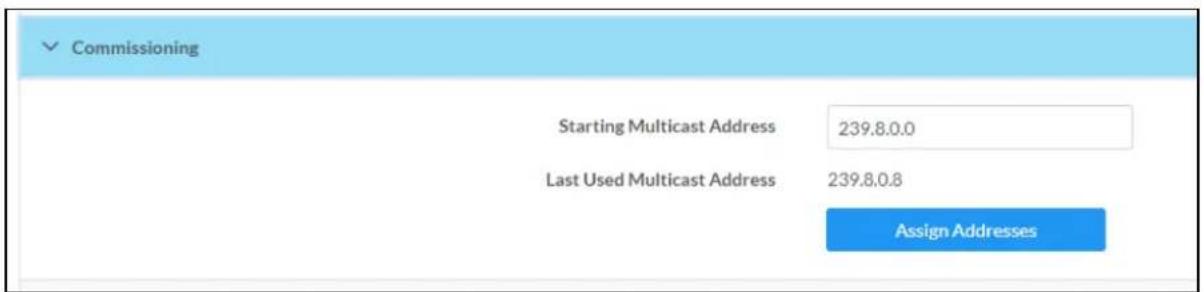
Click Assign Addresses to give each DM NAX transmitter in the DM-NAX-AUD-USB a unique multicast address beginning with the specified Starting Multicast Address. The valid range for Starting Multicast Address is 239.8.0.0 to 239.255.255.254.
NOTE: This will begin transmitting multicast traffic on your network, refer to the DM NAX Audio-over-IP System Design Guide document for details.
Output Channels
The Zones section contains the Volume and Mute settings for all zone outputs of the device, as well as an Edit option for more advanced settings within each zone.
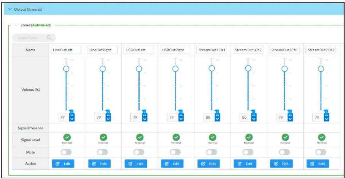
bar
| Name | LineOutLeft (%) | LineOutRight (%) | USBOutLeft (%) | USBOutRight (%) | StreamOut1Ch1 (%) | StreamOut1Ch2 (%) | StreamOut2Ch1 (%) | StreamOut2Ch2 (%) | |---|---|---|---|---|---|---|---|---| | Volume (%) | 79 | 79 | 79 | 79 | 80 | 80 | 79 | 79 | | Signal Presence | - | - | - | - | - | - | - | - | | Signal Level | Normal | Normal | Normal | Normal | Normal | Normal | Normal | Normal | | Mute | - | - | - | - | - | - | - | - | | Action | Edit | Edit | Edit | Edit | Edit | Edit | Edit | Edit |Signal Presence indicates whether or not an audio signal is detected in that zone.
Signal Level indicates if the signal is Clipping or Nominal (non-clipping).
- Nominal: The signal level is within normal operating bounds and below the clipping threshold.
- Clipping: The signal level is clipping or above the -3 dB warning threshold and in danger of clipping.
Give each zone a friendly name using the Name column of the Zones table. If the device is paired with a control system, these names may be overwritten by the control system's program.
To configure the zone volume, do one of the following:
- Move the Volume slider up to increase or down to decrease the zone volume.
- Click the % arrows to increase or decrease the zone volume. Values range from 0 to 100% adjustable in increments of 1%.
- Manually enter a value in the Volume field.
To mute all audio output from a zone, click its respective Mute button. To unmute the zone, click the Muted button.
Click Edit to view additional Zone and Output options.
Zone Settings
To configure the settings for an output channel, click the Edit button. The Edit Zone window appears.

Zone
Click Zone to access the settings for Tone and Delay.
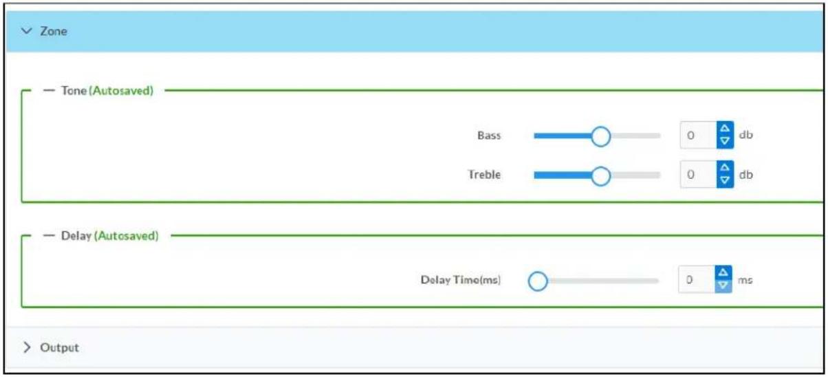
Tone
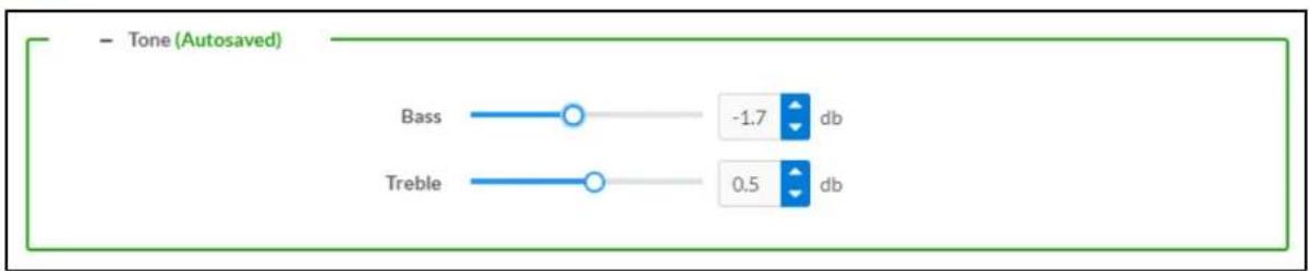
- Bass: To adjust the bass, do one of the following:
- Move the Bass slider to the right to increase or to the left to decrease the bass db.
- Click the db arrows to increase or decrease the db. Values range from -12 db to 12 db, adjustable in increments of .1 db.
- Manually enter a value in the Bass field.
- Treble: To adjust the treble, do one of the following:
- Move the Treble slider to the right to increase or to the left to decrease the treble db.
- Click the db arrows to increase or decrease the db. Values range from -12 db to 12 db, adjustable in increments of .1 db.
- Manually enter a value in the Treble field.
Delay

To set the delay, do one of the following:
- Move the Delay Time(ms) slider to the right to increase or to the left to decrease the delay time.
- Click the ms arrows to increase or decrease the delay. Values range from 0 ms to 85 ms, adjustable in increments of 1 ms.
- Manually enter a value in the Delay Time(ms) field.
NOTE: The Delay feature is only available on the line level output channels.
Output
Click Output to access the settings for Minimum/Maximum Volume, Signal, and the output Equalizer.

Minimum/Maximum Volume
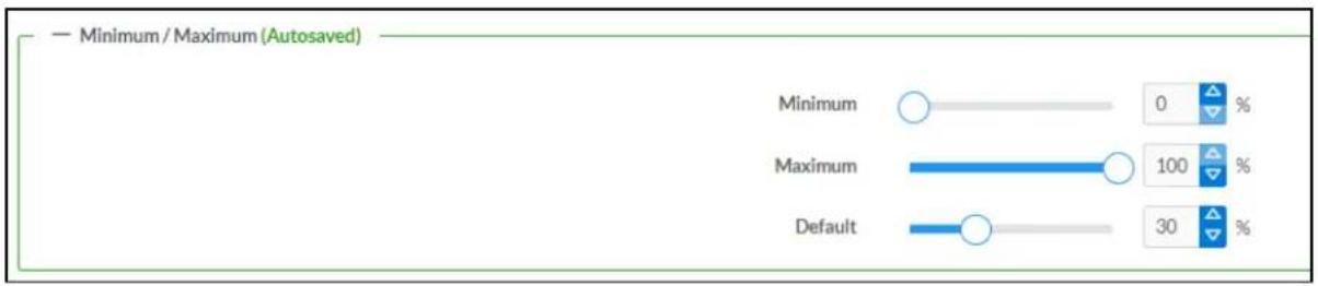
-
To set the minimum volume of the zone, do one of the following:
-
Move the Minimum slider to the right to increase or to the left to decrease the minimum volume.
- Click the % arrows to increase or decrease the minimum volume. Values range from 0 to 50%, adjustable in increments of 1%.
-
Manually enter a value in the Minimum field.
-
To set the maximum volume of the zone, do one of the following:
-
Move the Maximum slider to the right to increase or to the left to decrease the maximum volume.
- Click the % arrows to increase or decrease the maximum volume. Values range from 70 to 100%, adjustable in increments of 1%.
- Manually enter a value in the Maximum field.
NOTE: When a Minimum and Maximum volume are set, the 1-100% range represented by the Zone and Default volume controls are scaled to the range set. For example, if a Minimum of 10% and a Maximum of 80% are set for a zone, the 1-100% range of the Zone volume control is scaled to the 10%-80% range set as the Minimum and Maximum.
-
To set the default volume of the zone, do one of the following:
-
Move the Default slider to the right to increase or to the left to decrease the default volume.
- Click the % arrows to increase or decrease the default volume. Values range from 0 to 50% adjustable in increments of 1%.
- Manually enter a value in the Default field.
NOTE: The Default volume is applied as the Zone volume any time the zone receives a source route and no source was previously routed to that zone.
Signal

The Signal section is a read-only field that displays the Signal and Clipping status of the zone output.
- If an output signal is present but not clipping, Signal will display Present in green and Clipping will display None in green.
- If an output signal is present and clipping, Signal will display Present in green and Clipping will display Present in red.
- If no output signal is detected, Signal will display Not Present in red and Clipping will display None in green.
Equalizer Settings

Each output channel of the DM-NAX-AUD-USB has a dedicated ten-band equalizer that can be fully customized to tune the zone output signal to the needs of an install. Each band can have a discrete ga filter type, center frequency, and bandwidth set, and can also be bypassed. The equalizer itself can also be bypassed using the Speaker EQ Enabled toggle.
- Set the Speaker EQ Enabled toggle to the right position to enable the equalizer. Set the toggle to the left position to bypass the equalizer.
NOTE: When Speaker EQ Enabled is disabled, all equalizer bands are bypassed. This is a quick way to perform A/B testing of the entire EQ curve.
- With the Speaker EQ Enabled toggle in the right position, do the following to configure a given equalizer band:
a. To set a band's gain, do one of the following:
- Move the Gain slider up to increase or down to decrease the gain.
- Click the arrows to increase or decrease the gain. Values range from -40 dB to 20 dB, adjustable in increments of 0.1 dB.
- Manually enter a value in the Gain field.
b. Select a filter type from the Type drop-down menu. By default, all bands are set to the EQ filter type. Some filter types will disable other settings in their respective band while enabled. For example, selecting the LowPass filter type for a band will disable that band's Gain and Bandwidth settings, since the LowPass filter applies a fixed roll-off slope at a set frequency. The available filter types are:
- EQ: a fully parametric filter that can boost or cut a range of frequencies.
- Notch: a parametric filter designed to more precisely cut a frequency or range of frequencies. A notch filter can achieve a narrower bandwidth than the standard EQ parametric filter type.
- TrebleShelf: a filter that boosts or cuts all frequencies above a set frequency by a set gain.
- BassShelf: a filter that boosts or cuts all frequencies below a set frequency by a set gain.
- LowPass: a filter that fully cuts all frequencies above a set frequency using a fixed roll-off slope of -12 dB per octave.
- HighPass: a filter that fully cuts all frequencies below a set frequency using a fixed roll-off slope of -12 dB per octave.
c. Set a center frequency for the equalizer band to tune a specific portion of the audible frequency spectrum. To set the center frequency, do one of the following:
- Click the arrows to increase or decrease the frequency. Values range from 20 Hz to 20 kHz, adjustable in increments of 1 Hz. Each band has a default center frequency that will be applied if the Reset button at the bottom of the band is clicked.
- Manually enter a value in the Frequency field.
d. Set a bandwidth to determine how wide of a frequency range is effected by the equalizer band. To set the bandwidth, do one of the following:
- Click the arrows to increase or decrease the bandwidth. Values range from 0.1 octaves to 4.0 octaves, adjustable in increments of 0.1 octave.
- Manually enter a value in the Bandwidth field.
e. The individual Bypass controls allow you to bypass a single band of equalization at a time for more granular A/B testing of a single filter. Set a band's Bypass toggle to the right position to bypass that band. Set the toggle to the left position to disable the bypass. By default, Bypass is disabled.
f. Each equalizer band has a Reset button that will reapply the default settings for that band.
Click Done to return to the Settings tab of the web user interface.
Input Channels
The Input Channels section is used to configure the Name, Compensation, and Mute attributes of the front panel inputs on the DM-NAX-AUD-USB.
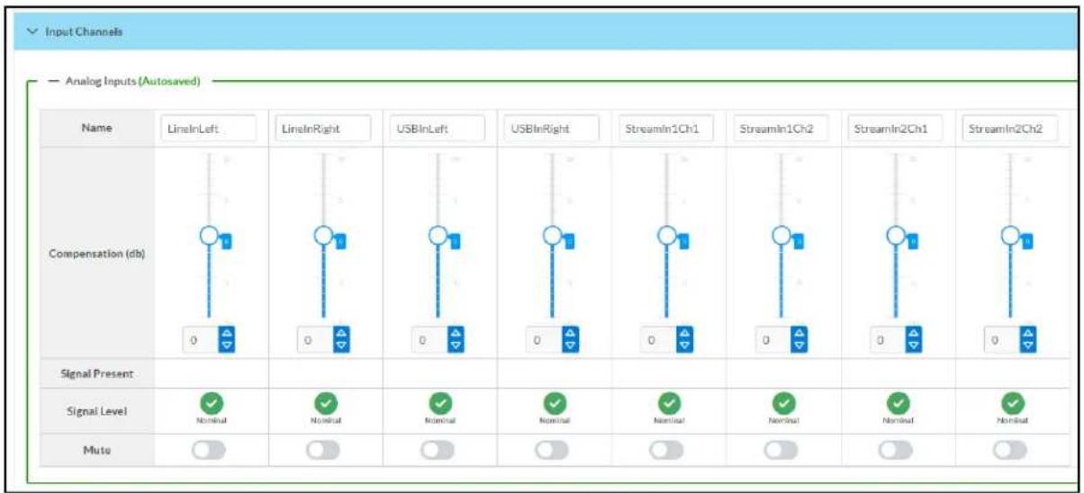
flowchart
graph TD
    A["Input Channels"] --> B["LineInLeft"]
    A --> C["LineInRight"]
    A --> D["USBInLeft"]
    A --> E["USBInRight"]
    A --> F["StreamIn1Ch1"]
    A --> G["StreamIn1Ch2"]
    A --> H["StreamIn2Ch1"]
    A --> I["StreamIn2Ch2"]
    J["Compensation (db)"] --> K["0"]
    J --> L["0"]
    J --> M["0"]
    J --> N["0"]
    J --> O["0"]
    J --> P["0"]
    J --> Q["0"]
    J --> R["0"]
    J --> S["0"]
    T["Signal Present"] --> U["Signal Level: Nominal, Nominal, Nominal, Nominal, Nominal, Nominal, Nominal, Nominal, Nominal"]
    U --> V["Muto: 0"]
    V --> W["0"]
    W --> X["0"]
    X --> Y["0"]
    Y --> Z["0"]
    Z --> AA["0"]
    AA --> AB["0"]
Configure Inputs
- If needed, enter a friendly name for each input in its Name field.
-
To set a level compensation adjustment for a given input, do one of the following:
-
Move the Compensation slider up to increase or down to decrease the level compensation. Compensation increases or decreases the level of the incoming audio signal on any of the physical inputs on the device's rear panel.
- Click the db arrows to increase or decrease the compensation. Values range from -10 dB to 10 dB, adjustable in increments of 1 dB.
-
Manually enter a value in the Compensation field.
-
To mute the signal from the corresponding input, set the Mute toggle to the right. To disable the mute, set the Mute toggle to the left. By default, Mute is disabled.
Monitor the device's input signals using the text indicators in the Signal Present and Clipping Detected columns:
• Signal Presence indicates whether or not a signal is detected in that zone.
- Clipping Detected indicates if the signal is Clipping or Nominal (non-clipping).
DM NAX Streams
The local inputs of the DM-NAX-AUD-USB can be made available as DM NAX audio-over-IP streams. Two network stream transmitters are available on the device. One transmitter will encode the local unbalanced line level input, and the other will encode the USB input audio.
Click NAX Streams to expand the tab and display the following information.

- Device is Master PTP Clock Source indicates whether the DM NAX device's PTP clock is the master clock on the network. Yes will be displayed in green when the local DM-NAX-AUD-USB's clock is the PTP master clock and No will be displayed in red when another PTP clock on the network is operating as the master clock.
- Master Clock Status displays the Master Clock ID of the device on the network that is currently acting as the master clock.
- PTP Priority: This sets the priority of the local DM NAX device's PTP clock relative to other clocks on the network. The default setting is 254 (one increment higher than the lowest possible value) so that the DM-NAX-AUD-USB will only operate as clock master if no other PTP master is present on the network. Valid values range from 1 to 255.
Configure Transmitters
To configure the DM NAX transmit stream, do the following.
- Enter a valid multicast address in the NAX Stream Address field.
- Enter a name in the NAX Stream Name field by which the stream can be identified. This stream name is associated with the DM NAX stream's multicast address by other DM NAX or AES67 devices, like a device hostname that resolves to a given IP address.
- Status indicates whether a stream is transmitting or not. When the stream has started or stopped, the Status column will update accordingly.
- Click the configure button (⚙️) in the Actions column. The Configure dialog appears:

-
Set the Auto Initiation toggle to the right position to enable auto initiation. Set the toggle to the left position to disable auto initiation.
-
If Auto Initiation is enabled for a given stream, the stream will begin transmitting automatically and will be available as a multicast stream on your network at the specified multicast address.
-
If Auto Initiation is disabled for the input, the stream will not begin transmitting until it is manually initiated.
-
To set the port number, do one of the following:
-
Click the arrows to increase or decrease the port number by increments of 1.
-
Manually enter a port number in the Port field. The default port number for DM NAX streams is 5004.
-
Click OK to save or click Cancel to cancel the changes.
Configure Receivers
-
Enter the multicast address of a transmitting stream in the Requested Stream Address field to subscribe the receiver to the stream.
-
Click the configure button (💡) in the Actions column. The Configure dialog appears:
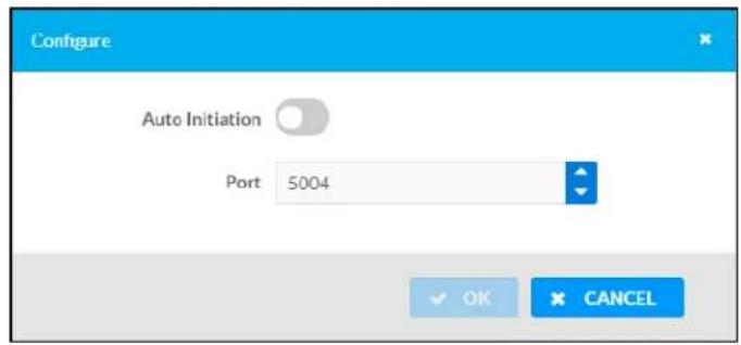
-
Set the Auto Initiation toggle to the right position to enable auto initiation. Set the toggle to the left position to disable auto initiation.
-
If Auto Initiation is enabled, the stream will begin automatically when the receiver subscribes to the transmitter.
-
If Auto Initiation is disabled, the stream will not begin until it is manually initiated.
-
To set the port number, do one of the following:
-
Click the arrows to increase or decrease the port number by increments of 1.
-
Manually enter a port number in the Port field. The default port number is 5004.
-
Click OK to save or click Cancel to cancel the changes.
Mixing
The Mixing matrix is used to route a local input or AES67 stream to an output on the DM-NAX-AUD-USB.
NOTE: To receive an AES67 stream from Dante devices, see OLH 1001151.

To route inputs to outputs on the device:
- Click the cells corresponding to the desired output that are to be paired for routing. Once a route is made, appears. The input that you have selected for a given row will route to the output corresponding to that row in the matrix.
- Use the arrows (or) at the left of the matrix to change pages to view all available inputs.
• To break a given route click or ✗
Each output can have any number of inputs routed to it. To adjust the mix setting for a route, click the dB value of the cell, then do one of the following:
- Move the slider up to increase or down to decrease the mix level.
- Click the arrows to increase or decrease the mix level.
- Manually enter a value in the field.

Residential Mode
This section provides the following information:
• System Setup on page 557
• Commissioning on page 561
• Output Channels on page 562
- Inputs on page 569
• NAX Streams on page 570
- Routing on page 573
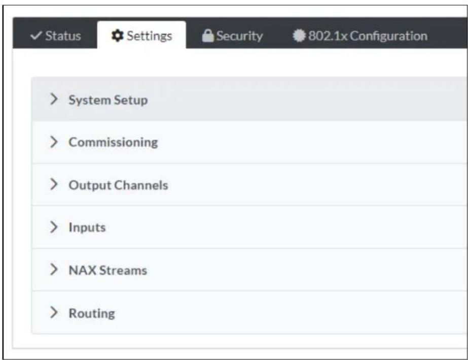
System Setup
The System Setup section displays information about the Date/Time, Auto Update, Network, Control System, Cloud Settings, and Device Modes.
Date/Time
Use the Date/Time section to configure the date and time settings of the DM-NAX-AUD-USB.

Time Synchronization
-
Set the Time Synchronization toggle to the right position to enable or left position to disable time synchronization. By default, time synchronization is enabled.
-
In the NTP Time Servers table, enter the URL of a NTP (Network Time Protocol) or SNTP (Simple Network Time Protocol) server. Up to three time servers can be added on a device.
- Click Synchronize Now to perform time synchronization between the device's internal clock and the time server.
Time Configuration
- Click on the Time Zone drop-down menu to select the applicable time zone.
- In the Date field, enter the current date.
- In the Time (24hr Format) field, enter the current time in 24-hour format.
Click the Save Changes button to save the settings.
Click Revert from the Actions drop-down menu to revert to the previous settings without saving.
Auto Update
The DM-NAX-AUD-USB can automatically check for and install firmware updates at scheduled intervals via the Auto Update feature.
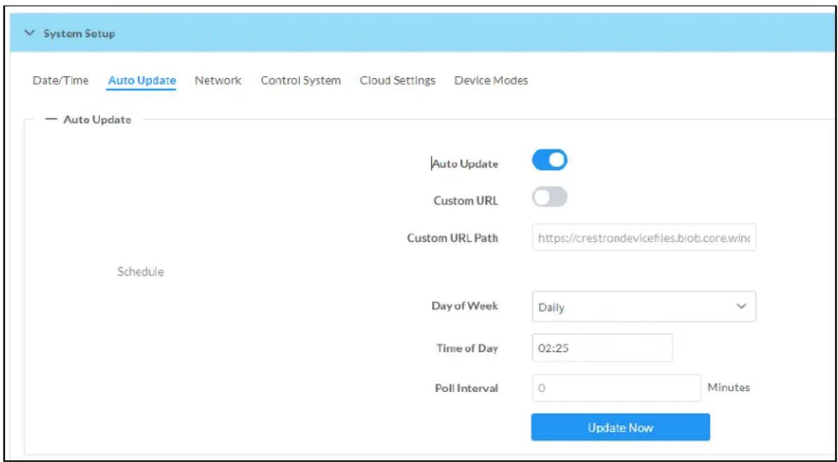
- Set the Auto Update toggle to the right position to enable Auto Update.
- Define the URL to download the updates by doing either of the following:
a. Use the default URL to download the updates from the Crestron server.
b. Use a custom URL. Set the Custom URL toggle to the right position to enable a custom URL. In the Custom URL Path text box, enter the path to a custom manifest file in the F or SFTP URL format. Use the Crestron Auto Update Tool to generate a custom manifest file, then store the file on an FTP (File Transfer Protocol) or SFTP (Secure File Transfer Protocol) server.
- Set a schedule for the automatic firmware update by doing either of the following:
a. Select the desired Day of Week and Time of Day (24-hour format) values.
b. Set the Poll Interval by entering a value from 60 to 65535 minutes. A value of 0 disables the Poll Interval.
4. Click Save Changes.
Clicking Update Now causes the device to check for a firmware update immediately. If a schedule was set in step 4 above, that schedule still remains in effect.
Network
The Network section contains network-related settings for the DM-NAX-AUD-USB, including the Hostname, Domain, Primary Static DNS, and Secondary Static DNS.
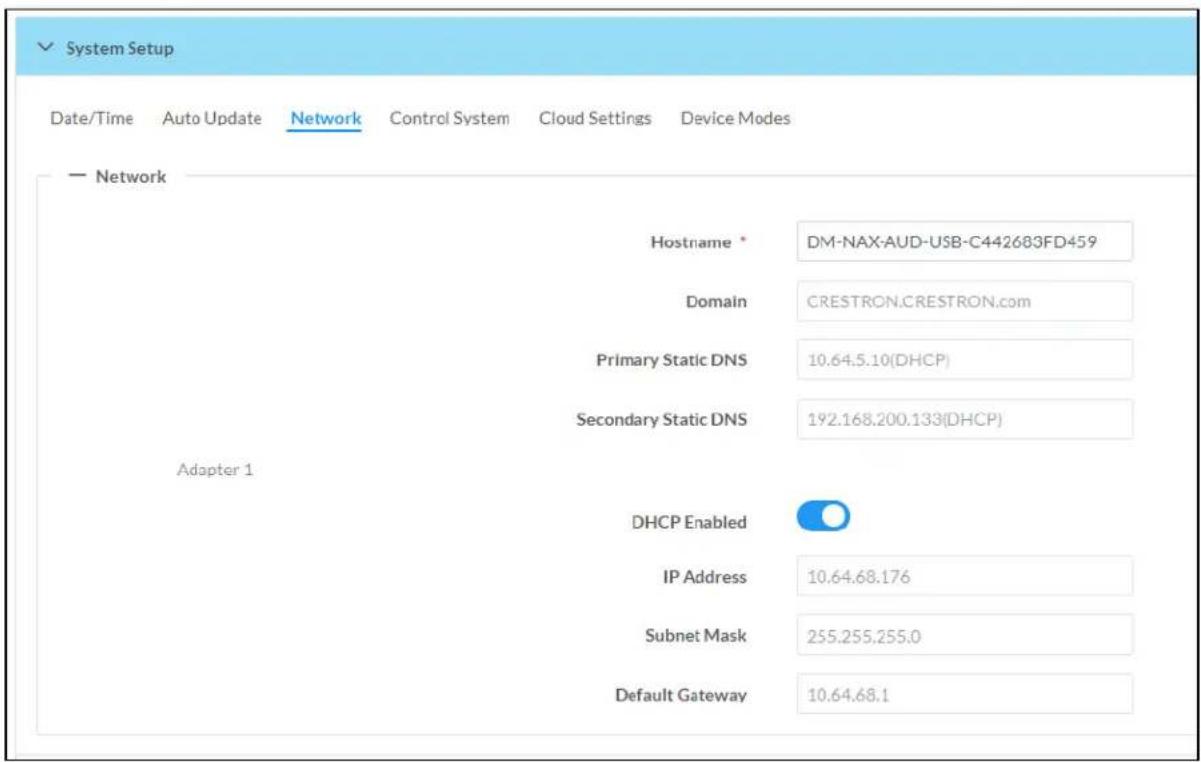
NOTE: By default, the host name of the DM-NAX-AUD-USB consists of the model name followed by the MAC address of the device. For example, DM-NAX-AUD-USB-00107FB58088.
Adapter 1
The Adapter 1 subheading contains settings for DHCP, IP Address, Subnet Mask, and Default Gateway of Ethernet adapter 1 on the rear panel of the device.
NOTE: DM NAX devices' internal processes use IP addresses in the 10x10 range. This IP range should be avoided when addressing DM NAX devices to prevent conflicts.
Set the DHCP toggle to enabled (right) or disabled (left) to specify whether the IP address of the DM-NAX-AUD-USB is to be assigned by a DHCP (Dynamic Host Configuration Protocol) server.
- Enabled: When DHCP is enabled (default setting), the IP address of the DM-NAX-AUD-USB is automatically assigned by a DHCP server on the local area network (LAN).
- Disabled: When DHCP is disabled, manually enter information in the following fields:
Primary Static DNS: Enter a primary DNS IP address.
- Secondary Static DNS: Enter a secondary DNS IP address.
IP Address: Enter a unique IP address for the DM-NAX-AUD-USB.
- Subnet Mask: Enter the subnet mask that is set on the network.
Default Gateway: Enter the IP address that is to be used as the network's gateway.
To save any new network entries, click Save Changes.
Control System

- Click the Encrypt Connection button to navigate to the Security tab to configure encryption settings.
- Enter the username in the Control System Username field.
- Enter the password in the Control System Password field.
- Enter the Room ID in the Room ID field.
- Enter the IP ID of the DM-NAX-AUD-USB in the IP ID field.
- Enter the IP address or hostname of the control system in the IP Address/Hostname field.
- Click the Save Changes button to save the new entries. The Control System Save message box appears, indicating that the control system settings were saved successfully. Click the Revert button to revert to the previous settings without saving.
Cloud Settings

Set the Cloud Settings toggle to enabled (right) or disabled (left) to specify whether the DM-NAX-AUD-USB can communicate with the XiO Cloud® platform.
Device Modes
Use the Device Modes section to configure the Application Mode.

- Application Mode: The Application Mode determines which options and controls are available.
Select Residential (Standard) or Commercial (Advanced). A Reboot confirmation message box appears.
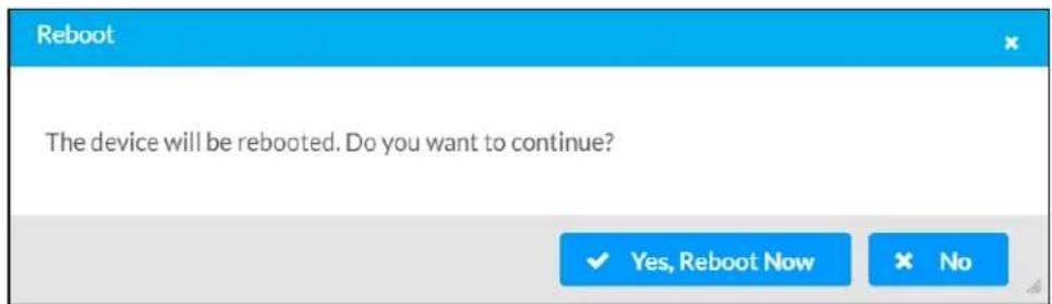
- Click Yes, Reboot Now to reboot the device into the selected mode. The Reboot message box appears.
- Wait for the device reboot to complete before attempting to reconnect to the device.
Commissioning
The Commissioning section provides a quick way to automatically assign multicast addresses to the device's internal audio-over-IP stream transmitters.

Click Assign Addresses to give each DM NAX transmitter in the DM-NAX-AUD-USB a unique multicast address beginning with the specified Starting Multicast Address. The valid range for Starting Multicast Address is 239.8.0.0 to 239.127.255.254.
NOTE: This will begin transmitting multicast traffic on your network, refer to the General Network Requirements document for details.
Output Channels
The Zones section contains the Volume and Mute settings for all zone outputs of the device, as well as a Configure option for more advanced settings within each zone.

Give each zone a friendly name using the Name column of the Zones table. If the device is paired with a control system, these names may be overwritten by the control system's program.
To configure the zone volume, do one of the following:
- Move the Volume slider to the right to increase or to the left to decrease the zone volume.
- Click the % arrows to increase or decrease the zone volume. Values range from 0 to 100%, adjustable in increments of 1%.
- Manually enter a value in the Volume field.
To mute all audio output from a zone, click its respective Mute button. To unmute the zone, click the Muted button.
Zone Settings
To configure zone settings, click the Configure button (Configure). The Edit Zone window appears.
Zone
Click Zone to access the settings for Tone, Balance, and Delay.

The Tone section provides adjustments for the Tone Profile, Bass, Treble, Loudness, and Night Mode settings of the zone output.
NOTE: The Tone Profile, Bass, Treble, and Loudness settings in the Tone section are all applied separately from the Equalizer Settings for the zone. This means that any adjustments made in the Tone section will stack with those made in the Equalizer Settings section.
- To select a tone profile preset for the zone, select an option from the Tone Profile drop-down menu. The available options are Off, Classical, Jazz, Pop, Rock, and Spoken Word. By default, Off is selected.
-
Bass: To adjust the bass, do one of the following:
-
Move the Bass slider to the right to increase or to the left to decrease the bass.
- Click the db arrows to increase or decrease the db. Values range from -12 db to 12 db, adjustable in increments of 1 db.
-
Manually enter a value in the Bass field.
-
Treble: To adjust the treble, do one of the following:
-
Move the Treble slider to the right to increase or to the left to decrease the treble.
- Click the db arrows to increase or decrease the db. Values range from -12 db to 12 db, adjustable in increments of 1 db.
-
Manually enter a value in the Treble field.
-
To enable the loudness setting on the zone output, slide the Loudness switch to the right. To disable loudness, slide the Loudness switch to the left.
-
The Night Mode feature applies subtle processing to restrict the dynamic range of the zone audio, to allow for lower listening levels at night or in rooms where higher listening levels would be disruptive. To select a dynamics processing level, select an option from the Night Mode drop-down menu. The available options are Off, Low, Medium, and High. By default, Off is selected.
Balance
To adjust the left/right balance of the stereo output signal, do one of the following:
- Move the Balance slider to the right to shift the stereo balance to the right channel or to the left to shift the balance to the left.
- Click the arrows to adjust the balance left or right. The up arrow shifts the balance to the right while the down arrow shifts the balance to the left.
- Manually enter a value in the Balance field. Values range from -50 to 50, adjustable in increments of 1. Positive values shift the balance to the right while negative values shift the balance to the left.
Delay
To set the delay, do one of the following:
- Move the Delay Time(ms) slider to the right to increase or to the left to decrease the delay time.
- Click the ms arrows to increase or decrease the delay. Values range from 0 ms to 85 ms, adjustable in increments of 1 ms.
- Manually enter a value in the Delay Time(ms) field.
NOTE: The Delay feature is only available on the line level output channels.
Output
Click Output to access the settings for Minimum/Maximum Volume, Stereo/Mono, Signal, Bussing Volume Offset, Signal Generator, and Equalizer Settings.
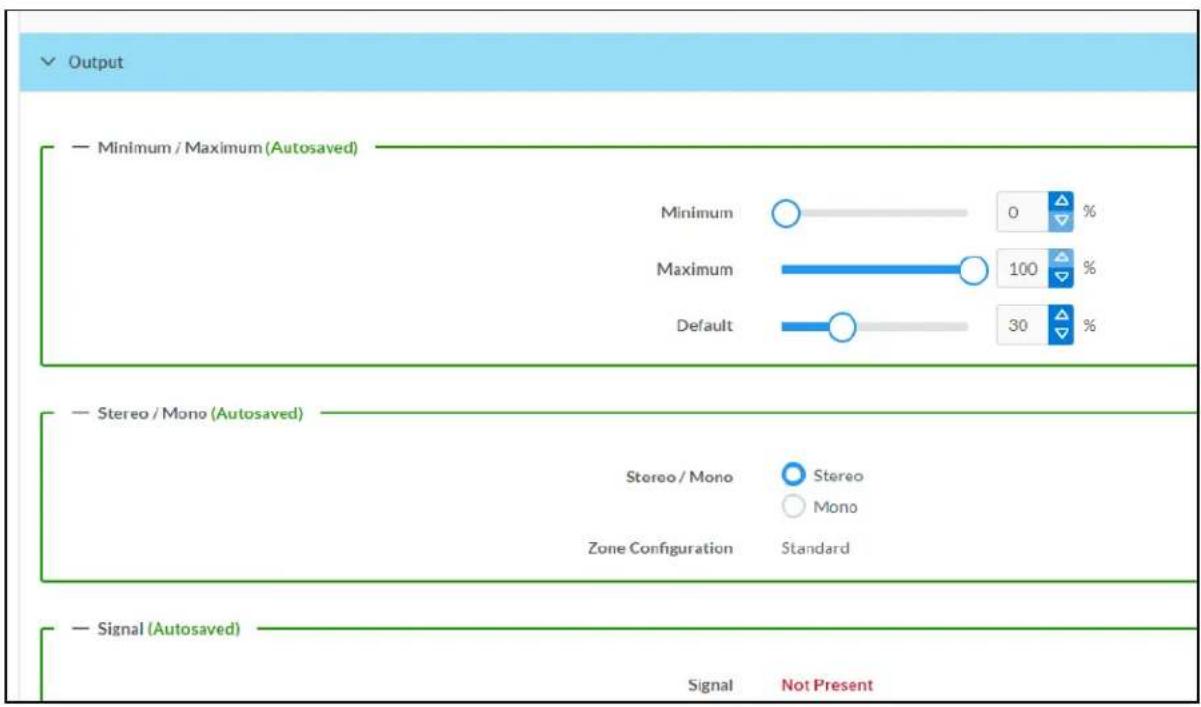
Minimum/Maximum Volume

-
To set the minimum volume of the zone, do one of the following:
-
Move the Minimum slider to the right to increase or to the left to decrease the minimum volume.
- Click the % arrows to increase or decrease the minimum volume. Values range from 0 to 50%, adjustable in increments of 1%.
-
Manually enter a value in the Minimum field.
-
To set the maximum volume of the zone, do one of the following:
-
Move the Maximum slider to the right to increase or to the left to decrease the maximum volume.
- Click the % arrows to increase or decrease the maximum volume. Values range from 70 to 100%, adjustable in increments of 1%.
- Manually enter a value in the Maximum field.
NOTE: When a Minimum and Maximum volume are set, the 1-100% range represented by the Zone and Default volume controls are scaled to the range set. For example, if a Minimum of 10% and a Maximum of 80% are set for a zone, the 1-100% range of the Zone volume control is scaled to the 10%-80% range set as the Minimum and Maximum.
-
To set the default volume of the zone, do one of the following:
-
Move the Default slider to the right to increase or to the left to decrease the default volume.
- Click the % arrows to increase or decrease the default volume. Values range from 0 to 50% adjustable in increments of 1%.
- Manually enter a value in the Default field.
NOTE: The Default volume is applied as the Zone volume any time the zone receives a source route and no source was previously routed to that zone.
Stereo/Mono

Select either Stereo or Mono from the Stereo/Mono radio buttons. If Stereo is selected, both output channels can have independent audio content. If Mono is selected, both output channels receive the same audio content.
Signal

The Signal section is a read-only field that displays the Signal and Clipping status of the zone output.
- If an output signal is present but not clipping, Signal will display Present in green and Clipping will display None in green.
- If an output signal is present and clipping, Signal will display Present in green and Clipping will display Present in red.
- If no output signal is detected, Signal will display Not Present in red and Clipping will display None in green.
Bussing Volume Offset

Bussing Volume Offset is an additional level compensation applied to the zone relative to any other zones it is grouped with via the Bussing feature.
To set the bussing volume offset, do one of the following:
- Move the Bussing Volume Offset slider to the right to increase or to the left to decrease the offset.
- Click the db arrows to increase or decrease the offset. Values range from -12 dB to 12 dB, adjustable in increments of 1 dB.
- Manually enter a value in the Bussing Volume Offset field.
Signal Generator

The DM-NAX-AUD-USB has a built-in signal generator that allows an integrator to send an audio signal to the output for testing purposes.
-
To route the signal generator to the zone output, click the Signal Generator button so that it displays Active and is highlighted in blue. To unroute the signal generator on the zone output, click the Signal Generator button so that it displays Inactive and is highlighted in grey. By default, the signal generator is not routed to the zone output.
-
To adjust the signal generator's volume, do one of the following:
-
Move the Signal Generator Volume slider right to increase or left to decrease the volume.
- Click the arrows to increase or decrease the signal generator volume. Values range from 0 to 100, adjustable in increments of 1.
- Manually enter a value in the Signal Generator Volume field.
Equalizer Settings

bar
| Band | Gain | Frequency | Bandwidth | Bypass | Actions | |--------|------|-----------|------------|---------|---------| | Band01 | 0 | 32 | 0.33 | | Reset | | Band02 | 0 | 64 | 0.33 | | Reset | | Band03 | 0 | 125 | 0.33 | | Reset | | Band04 | 0 | 250 | 0.33 | | Reset | | Band05 | 0 | 500 | 0.33 | | Reset | | Band06 | 0 | 1000 | 0.33 | | Reset | | Band07 | 0 | 2000 | 0.33 | | Reset | | Band08 | 0 | 4000 | 0.33 | | Reset | | Band09 | 0 | 8000 | 0.33 | | Reset | | Band10 | 0 | 16000 | 0.33 | | Reset |The zone output of the DM-NAX-AUD-USB has a dedicated ten-band equalizer that can be fully customized to tune the zone output signal to the needs of an install. Each band can have a discrete ga filter type, center frequency, and bandwidth set, and can also be bypassed. The equalizer itself can also be bypassed using the Speaker EQ Enabled toggle.
- Set the Speaker EQ Enabled toggle to the right position to enable the equalizer. Set the toggle to the left position to bypass the equalizer.
NOTE: When Speaker EQ Enabled is disabled, all equalizer bands are bypassed. This is a quick way to perform A/B testing of the entire EQ curve.
- With the Speaker EQ Enabled toggle in the right position, do the following to configure a given equalizer band:
a. To set a band's gain, do one of the following:
- Move the Gain slider up to increase or down to decrease the gain.
- Click the arrows to increase or decrease the gain. Values range from -40 dB to 20 dB, adjustable in increments of 0.1 dB.
- Manually enter a value in the Gain field.
b. Select a filter type from the Type drop-down menu. By default, all bands are set to the EQ filter type. Some filter types will disable other settings in their respective band while enabled. For example, selecting the LowPass filter type for a band will disable that band's Gain and Bandwidth settings, since the LowPass filter applies a fixed roll-off slope at a set frequency. The available filter types are:
- EQ: a fully parametric filter that can boost or cut a range of frequencies.
- Notch: a parametric filter designed to more precisely cut a frequency or range of frequencies. A notch filter can achieve a narrower bandwidth than the standard EQ parametric filter type.
- TrebleShelf: a filter that boosts or cuts all frequencies above a set frequency by a set gain.
- BassShelf: a filter that boosts or cuts all frequencies below a set frequency by a set gain.
- LowPass: a filter that fully cuts all frequencies above a set frequency using a fixed roll-off slope of -12 dB per octave.
- HighPass: a filter that fully cuts all frequencies below a set frequency using a fixed roll-off slope of -12 dB per octave.
c. Set a center frequency for the equalizer band to tune a specific portion of the audible frequency spectrum. To set the center frequency, do one of the following:
- Click the arrows to increase or decrease the frequency. Values range from 20 Hz to 20 kHz, adjustable in increments of 1 Hz. Each band has a default center frequency that will be applied if the Reset button at the bottom of the band is clicked.
- Manually enter a value in the Frequency field.
d. Set a bandwidth to determine how wide of a frequency range is effected by the equalizer band. To set the bandwidth, do one of the following:
- Click the arrows to increase or decrease the bandwidth. Values range from 0.1 octaves to 4.0 octaves, adjustable in increments of 0.1 octave.
- Manually enter a value in the Bandwidth field.
e. The individual Bypass controls allow you to bypass a single band of equalization at a time for more granular A/B testing of a single filter. Set a band's Bypass toggle to the right position to bypass that band. Set the toggle to the left position to disable the bypass. By default, Bypass is disabled.
f. Each equalizer band has a Reset button that will reapply the default settings for that band.
Click Done to return to the Settings tab of the web user interface.
Inputs
The Inputs section is used to configure the Name, Compensation, and Mute attributes of the available analog, digital, and media streaming inputs on the DM-NAX-AUD-USB.

Configure Inputs
-
If needed, enter a friendly name for each input in its Name field.
-
To set a level compensation adjustment for a given input, do one of the following:
-
Move the Compensation slider up to increase or down to decrease the level compensation. Compensation increases or decreases the level of the incoming audio signal on any of the physical inputs on the device's rear panel.
- Click the db arrows to increase or decrease the compensation. Values range from -10 dB to 10 dB, adjustable in increments of 1 dB.
-
Manually enter a value in the Compensation field.
-
To mute the signal from the corresponding input, set the Mute toggle to the right. To disable the mute, set the Mute toggle to the left. By default, Mute is disabled.
Monitor the device's input signals using the text indicators in the Signal Present and Clipping Detected columns:
• Signal Presence indicates whether or not a signal is detected in that zone.
- Clipping Detected indicates if the signal is Clipping or Nominal (non-clipping).
NAX Streams
The two local inputs of the DM-NAX-AUD-USB can be made available as DM NAX audio-over-IP streams.
Click NAX Streams to expand the tab and display the following information.
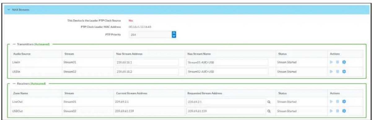
- Device is Master PTP Clock Source indicates whether the device is the master for PTP on the network. Yes will be displayed in green when the local DM-NAX-AUD-USB is the PTP clock master and No will be displayed in red when another PTP clock on the network is operating as the master clock.
- Master Clock Status displays the Master Clock ID of the device on the network that acts as the Master Clock.
- PTP Priority: This sets the priority of the local DM NAX device's PTP clock relative to other clocks on the network. The default setting is 254 (one increment higher than the lowest possible value) so that the DM-NAX-AUD-USB will only operate as clock master if no other PTP master is present on the network. Valid values range from 1 to 255.
Configure Transmitters
To configure a DM NAX transmit stream, do the following.
- Enter a valid multicast address in the NAX Stream Address field.
- Enter a name in the NAX Stream Name field by which the stream can be identified. This stream name is associated with the DM NAX stream's multicast address by other DM NAX or AES67 devices, like a device hostname that resolves to a given IP address.
- Status indicates whether a stream is transmitting or not. When the stream has started or stopped, the Status column will update accordingly.
- Click the configure button (💡) in the Actions column. The Configure dialog appears:

-
Set the Auto Initiation toggle to the right position to enable auto initiation. Set the toggle to the left position to disable auto initiation.
-
If Auto Initiation is enabled for a given stream, the stream will begin transmitting automatically and will be available as a multicast stream on your network at the specified multicast address.
-
If Auto Initiation is disabled for the input, the stream will not begin transmitting until it is manually initiated.
-
To set the port number, do one of the following:
-
Click the arrows to increase or decrease the port number by increments of 1.
-
Manually enter a port number in the Port field. The default port number for DM NAX streams is 5004.
-
Click OK to save or click Cancel to cancel the changes.
Configure Receivers
- Enter the multicast address of a transmitting stream in the Requested Stream Address field to subscribe the receiver to the stream.
- Click the configure button (💡) in the Actions column. The Configure dialog appears:

-
Set the Auto Initiation toggle to the right position to enable auto initiation. Set the toggle to the left position to disable auto initiation.
-
If Auto Initiation is enabled, the stream will begin automatically when the receiver subscribes to the transmitter.
-
If Auto Initiation is disabled, the stream will not begin until it is manually initiated.
-
To set the port number, do one of the following:
-
Click the arrows to increase or decrease the port number by increments of 1.
-
Manually enter a port number in the Port field. The default port number is 5004.
-
Click OK to save or click Cancel to cancel the changes.
Routing
The Routing section is used to route a local input or AES67 stream to a Zone on the DM-NAX-AUD-USB.
NOTE: To receive an AES67 stream from Dante devices, see OLH 1001151.

To route an input to a zone, click the box in the routing matrix where the zone's row overlaps the corresponding input's column. Once a route is made, appears. To break a given route click or . To route a single input to all zones, click on the icon under the input's name.
Security
Click the Security tab to configure security for users and groups and to allow different levels of access to the DM-NAX-AUD-USB functions. By default, security is disabled.

Select Encrypt and Validate, Encrypt, or OFF in the SSL Mode drop-down menu, to specify whether to use encryption. By default, SSL Mode is set to OFF.
Current User
Click the Current User tab to view read-only information or to change the password for the current user.

-
Click the Change Current User Password button to provide a new password for the current user.
-
In the Change Password dialog, enter the current password in the Current Password field, the new password in the Password field, and then re-enter the same new password in the Confirm Password field.

- Click OK to save or click Cancel to cancel the changes.
Users
Click the Users tab to view and edit user settings. The Users tab can be used to add or remove local and Active Directory users and preview information about users.

Use the Search Users field to enter search term(s) and display users that match the search criteria.
If users listed in the Users table span across multiple pages, navigate through the list of users by clicking a page number or by using the left or right arrows at the bottom of the Users pane to move forward or backward through the pages.
Each page can be set to display 5, 10, or 20 users by using the drop-down menu to the right of the navigation arrows.
Information about existing users is displayed in table format and the following details are provided for each user.
- Username: Displays the name of the user.
- AD User: Displays whether the user requires authentication using Active Directory.
Click the corresponding button in the Actions column to view detailed user information or to delete the user.
To create a new user, click the Create User button.
Create a New Local User
-
Click the Create User button in the User tab.
-
In the Create User dialog, enter the following:

a. Enter a user name in the Name field. A valid user name can consist of alphanumeric characters (letters a-z, A-Z, numbers 0-9) and the underscore "_" character.
b. Enter a password in the Password field; re-enter the same password in the Confirm Password field.
c. Assign the access level by selecting one or more groups from the Groups drop-down list.
NOTE: Make sure that the Active Directory User toggle is disabled.
- Click OK to save or click Cancel to cancel the changes.
Add an Active Directory User
Users cannot be created or removed from the Active Directory server, but access can be granted to an existing user in the Active Directory server.
To grant access to an Active Directory user, you can either add the user to a local group on the DM-NAX-AUD-USB, or add the Active Directory group(s) that they are a member of to the DM-NAX-AUD-USB.
To add an Active Directory user.
- Click the Create User button.
- In the Create User dialog, enter the following.

a. Enter a user name in the Name field in the format "Domain\UserName", for example "crestronlabs.com\JohnSmith". Valid user names can contain alphanumeric characters (letters a-z, A-Z, numbers 0-9) and the underscore "_" character.
b. Select one or more groups from the Groups drop-down list.
NOTE: Make sure that the Active Directory User toggle is set to enabled.
- Click OK to save or click Cancel to cancel the changes.
Delete User
Click the trashcan button (☐) in the Actions column to delete the user. Click Yes when prompted to delete the user or No to cancel the deletion.
After a user is removed from a group, they lose any access rights associated with that group. Note that the user account is not deleted by the delete user operation.
View User Details
Click the information button (0) in the Actions column to view information for the selected user. The User Details dialog displays the following information for the selected user.
- Name: Displays the name of the selected user.
• Active Directory User: Displays whether the user is an Active Directory user. - Group: Displays group(s) the selected user is part of.

Click OK to close the User Details dialog and to return to the Users tab.
Update User Details

- Click the edit button() in the Actions column to update information for the selected user.
- Enter a password in the Password field; re-enter the same password in the Confirm Password field.
- Select one or more groups to assign the user to from the Groups drop-down list.
- Click OK to save or click Cancel to cancel the changes.
The Update User dialog also displays the following read-only information for the selected user.
• Name: Displays the name of the user.
• Active Directory User: Displays whether the user is an Active Directory user.
Groups
Click the Groups tab to view and edit group settings. The Groups tab can be used to add local and Active Directory groups, remove local and Active Directory groups, and preview information about a group.
Use the Search Groups field to enter search term(s) and display groups that match the search criteria.
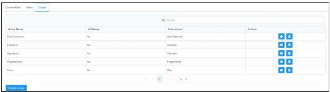
If groups listed in the Groups table span across multiple pages, navigate through the groups by clicking a page number or by using the left or right arrows at the bottom of the Groups pane to move forward or backward through the pages.
Additionally, each page can be set to display 5, 10, or 20 groups by using the drop-down menu to the right of the navigation arrows.
Existing groups are displayed in a table and the following information is provided for each group:
• Group Name: Displays the name of the group.
• AD Group: Displays whether the group requires authentication using Active Directory.
- Access Level: Displays the predefined access level assigned to the group (Administrator, Programmer, Operator, User, or Connect).
Click the corresponding button in the Actions column to view detailed group information (☐) or to delete ☐ selected group.
Click on the Create Group button in the Groups tab to create new group.
Create Local Group

- Click the Create Group button.
- In the Create Group dialog, enter the following:
a. Enter the group name in the Name field.
b. Assign the group access level by selecting a predefined access level (Administrator, Connect, Operator, Programmer, User) from the Access Level drop-down list.
NOTE: Make sure that the Active Directory Group toggle is disabled.
- Click OK to save. Click Cancel to cancel the changes.
Add Active Directory Group
A group cannot be created or removed from the Active Directory server, but access can be granted to a existing group in Active Directory.

Once the group is added, all members of that group will have access to the DM-NAX-AUD-USB.
- Click the Create Group button.
- In the Create Group dialog enter the following:
a. Enter the group name in the Name field, for example "Engineering Group". Note that group names are case sensitive; a space is a valid character that can be used in group names.
- Assign the group access level by selecting a predefined access level (Administrator, Connect, Operator, Programmer, User) from the Access Level drop-down list.
NOTE: Make sure that the Active Directory Group toggle is enabled.
- Click OK to save. Click Cancel to cancel the changes.
Delete a Group
Click the trashcan button (☐) in the Actions column to delete a group. Click Yes when prompted to delete the group or No to cancel the deletion.
When a group is deleted, users in the group are not removed from the device or Active Directory server. However, because a user's access level is inherited from a group(s), users within the deleted group will lose access rights associated with the group.
View Group Details
Click the information button (6) in the Actions column to view information for the selected group. The Group Details dialog lists the following information for the selected group.

• Name: Displays the name of the group.
- Access Level: Displays the access level of the group and its users.
• Active Directory Group: Displays whether the group is an Active Directory group.
Click OK to close the Group Details dialog and to return to the Groups tab.
802.1x Configuration
The DM-NAX-AUD-USB has built-in support for the 802.1X standard (an IEEE network standard designed to enhance the security of wireless and Ethernet LANs. The standard relies on the exchange of messages between the device and the network's host, or authentication server), allowing communication with the authentication server and access to protected corporate networks.

To Configure DM-NAX-AUD-USB for 802.1X Authentication
-
Set the IEEE 802.1X Authentication toggle to enabled. This will enable all options on the 802.1X dialog.
-
Select the Authentication method: EAP-TLS Certificate or EAP-MSCHAP V2 Password according to the network administrator's requirement.
-
Do either one of the following:
- Select EAP-TLS Certificate, click Action/Manage Certificates to upload the required machine certificate. The machine certificate is an encrypted file that will be supplied by the network administrator, along with the certificate password.
- Select EAP-MSCHAP V2 Password, enter the username and password supplied by the network administrator into the Username and Password fields. This method does not require the use of a machine certificate, only the user name and password credentials.
- If you enabled the Enable Authentication Server Validation option, this will enable the Select Trusted Certificate Authoritie(s) list box which contains signed Trusted Certificate Authorities (CAs) preloaded into the DM-NAX-AUD-USB.
Select the check box next to each CA whose certificate can be used for server validation, as specified by the network administrator.
If the network does not use any of the listed certificates, the network administrator must provide a certificate, which must be uploaded manually via the Manage Certificates functionality.
-
If required, type the domain name of the network in the Domain field.
-
When the 802.1X settings are configured as desired, click Save Changes to save the changes to the device and reboot it. Click Revert to cancel any changes.
Access the Web Interface With the Crestron Toolbox Application
To access the web interface by opening a web browser within the Crestron Toolbox™ application, do the following:
-
Open the Crestron Toolbox application.
-
From the Tools menu, select Device Discovery Tool. You can also access the Device Discovery Tool by clicking the Device Discovery Tool button ( ) in the Crestron Toolbox toolbar. The DM-NAX-AUD-USB is discovered and listed in the device list on the left side of the screen. The associated host name, IP address, and firmware version are also displayed.
NOTE: If there is security software running on the computer, a security alert might be displayed when the Crestron Toolbox application attempts to connect to the network. Make sure to allow the connection, so that the Device Discovery Tool can be used.
-
In the Device Discovery Tool list, double-click your device.
-
Enter your credentials in the Authentication Required dialog that opens, and then click Log In.
-
Click the Web Configuration button in the Configuration page displayed on the left side of the Device Discovery Tool.
DM-NAX-BTIO-1G
This section describes how to configure the DM-NAX-BTIO-1G.
Web Interface Configuration
The DM-NAX-2XLRI-1G web interface allows you to view status information and configure network and device settings.
Access the Web Interface
To access the web interface, do either of the following:
- Access the Web Interface with a Web Browser on page 586
- Access the Web Interface With the Crestron Toolbox™ Application on page 640
The web interface is accessed from a web browser. The following table lists operating systems and their corresponding supported web browsers.
Operating System and Supported Web Browsers
| OPERATING SYSTEM SUPPORTED WEB BROWSERS | |
| Windows® operating system | ChromeTM web browser, version 31 and laterFirefox® web browser, version 31 and laterInternet Explorer web browser, version 11 and laterMicrosoft Edge web browser |
| macOS® operating system | Safari® web browser, version 6 and laterChrome web browser, version 31 and laterFirefox web browser, version 31 and later |
Access the Web Interface with a Web Browser
- Enter the IP address of the DM-NAX-BTIO-1G into a web browser.
NOTE: To obtain the IP address, use the Device Discovery Tool option in Crestron Toolbox™ application or an IP scanner application.
- If you are creating a user account for the first time, do the following; otherwise, skip to step 3.
a. Enter a username in the Username field.
b. Enter a password in the Password field.
c. Re-enter the same password in the Confirm Password field.

CRESTRON®
▲ DEVICE FIRST BOOT

d. Click Create User. The Device Administration page appears.

CRESTRON®
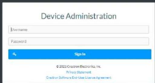
- Enter the username in the Username field.
- Enter the password in the Password field.
- Click Sign In.
Action
The Action drop-down menu is displayed at the top right side of the interface and provides quick access to common device functions:
- Save Changes
- Revert
- Reboot
- Restore
- Update Firmware
- Download Logs
- Manage Certificates

Save Changes
Click Save Changes to save any changes made to the configuration settings.
Revert
Click Revert to revert the device back to the last saved configuration settings.
Reboot the DM-NAX-BTIO-1G
Certain changes to the settings may require the DM-NAX-BTIO-1G to be rebooted to take effect. To reboot the device, do the following:
- Click Reboot in the Actions drop-down menu. The Confirmation message box appears.

- Click Yes, Reboot Now to reboot the device. The Reboot message box appears.
Wait for the device reboot to complete before attempting to reconnect to the device.
Restore to Factory Default Settings
- Click Restore in the Actions drop-down menu to restore the settings of the DM-NAX-BTIO-1G to factory defaults.
NOTE: When settings are restored, all settings, including the network settings, will revert to the factory default. If a static IP address is set, restoring the device to factory default settings will revert the IP address to the default DHCP mode.

- Click Yes in the Confirmation dialog to restore the DM-NAX-BTIO-1G to factory settings. Click No to cancel the restore operation.
A dialog is displayed again, indicating that the restore process was successful and that the device rebooted.
You can also restore to factory settings by pressing and holding the SETUP button on the rear panel of the device with power disconnected then connect the power supply and continue to hold SETUP button for 30 seconds.
Update Firmware
-
Click Update Firmware in the Actions drop-down menu.
-
In the Firmware Upgrade dialog, click + Browse.
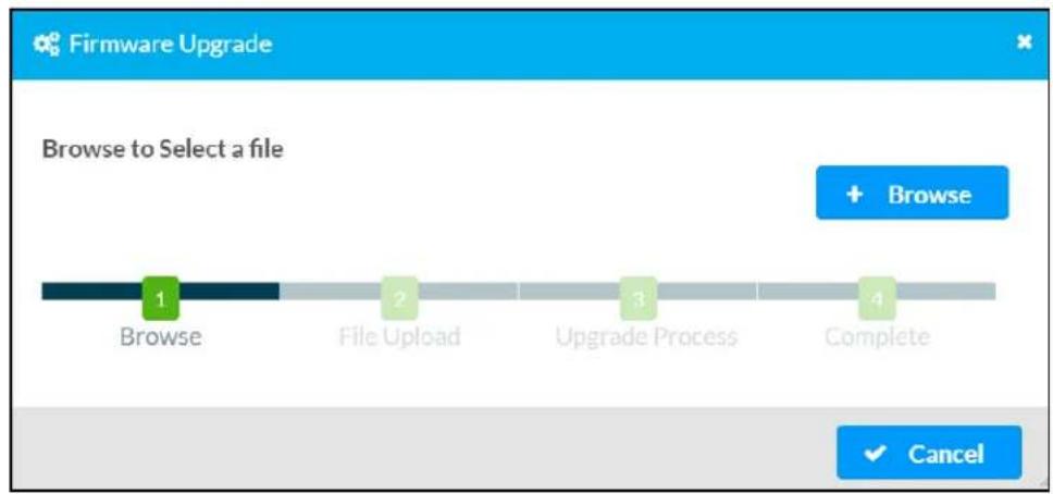
- Locate and select the desired firmware file, and then click Open. The selected firmware file name is displayed in the Firmware Upgrade dialog.
- Click Load and wait for the progress bar to complete and for the OK button in the message to become clickable.
- Click OK. The device with new firmware can now be accessed.
Download Logs
- Click Download Logs in the Actions drop-down menu to download the device message logs for diagnostic purposes.
The log file is downloaded to the Downloads folder of the PC.
Manage Certificates
Use the Manage Certificates dialog to add, remove, and manage certificates used in 802.1x and other protected networks.
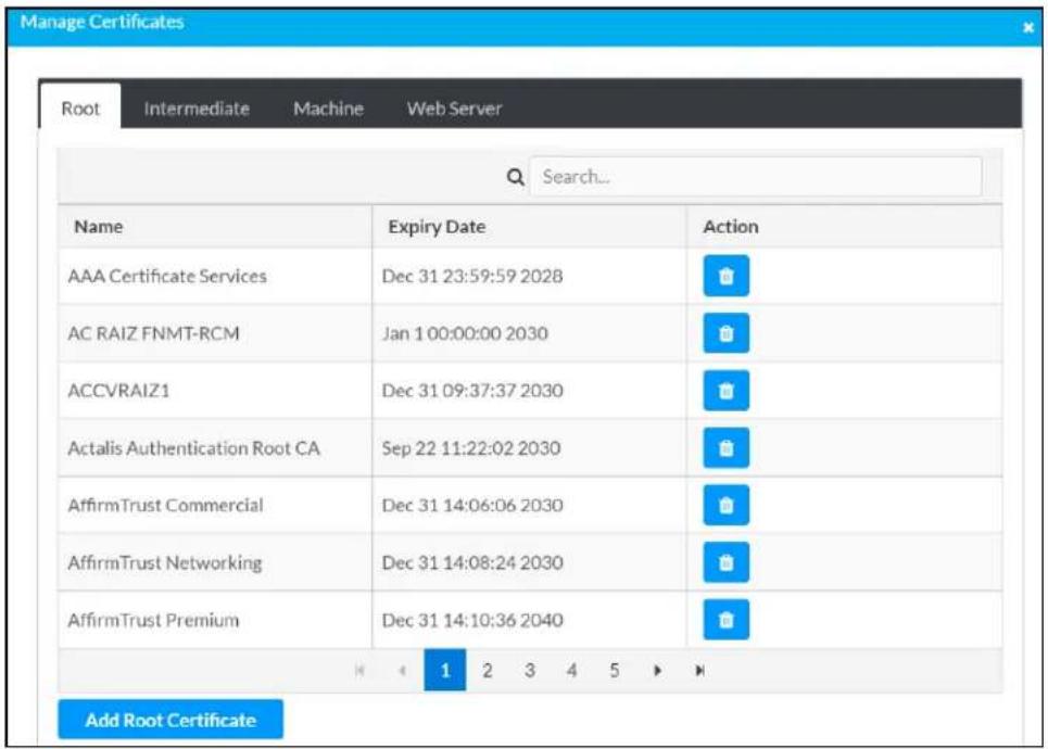
-
Click Manage Certificates in the Actions drop-down menu. The following certificate tabs are displayed:
-
Root: The Root certificate is used by the DM-NAX-BTIO-1G to validate the network's authentication server. The DM-NAX-BTIO-1G has a variety of Root certificates, self-signed by trusted CAs (Certificate Authorities) preloaded into the device. Root certificates must be self-signed.
- Intermediate: The Intermediate store holds non self-signed certificates that are used to validate the authentication server. These certificates will be provided by the network administrator if the network does not use self-signed Root certificates.
- Machine: The machine certificate is an encrypted PFX file that is used by the authentication server to validate the identity of the DM-NAX-BTIO-1G. The machine certificate will be provided by the network administrator, along with the certificate password. For 802.1x, only one machine certificate can reside on the device.
- Web Server: The Web Server certificate is a digital file that contains information about the identity of the web server.
To Add Certificates
- Click the corresponding certificate tab.
- Click the Add Root Certificate button.
- Click the + Browse button.
- Locate and select the file, and then click the Open button.
NOTE: If the certificate is a Machine Certificate, enter the password provided by the network administrator.
- Click OK. This will add the certificate to the list box, displaying the file name and expiration date.
The certificate is now available for selection and can be loaded to the device.
To Delete Certificates
- Click the corresponding certificate tab.
- Click the trashcan button ( ) in the Actions column to delete the certificate.
- Click Yes when prompted to delete the certificate or No to cancel the deletion.
Status
The Status tab is the first page displayed when opening the interface of the DM-NAX-BTIO-1G. It displays general information about the DM-NAX-BTIO-1G (such as Model Name, Firmware Version, and Serial Number), current network settings (such as Host Name and IP Address, etc.), and input and output ports' current status.
The Status tab can be accessed at any time by clicking the Status tab of the DM-NAX-BTIO-1G interface.

Information displayed on the Status tab is organized into different sections.
Device
The Device section displays the Model, Firmware Version, and Serial Number of the DM-NAX-BTIO-1G.

Click + More Details to review additional information about the DM-NAX-BTIO-1G.
| — More Details | |
| DM-NAX-BTIO-1G 1.0.0033.11191 | |
| Build Feb 13 2024 (531246) | |
| Updater 1.0.0033.11191 | |
| Bootloader 1.00.00 | |
| CCUI Version 1.1327.1 | |
| XIOSDK 3.8.2 | |
| IoTSDK 1.11.0 | |
| Build time 11:19:07 | |
| Product ID Cx7A09 | |
| Revision ID Cx0200 | |
| HDCP2X-SKE | |
| HDCP2X-SKE HDCP2X-SKE [v9.0000.00000,#FFFFFFF] | |
| PRE-BOOT [v9.0000.00000] | |
| BOOTLOADER [v9.0000.00000] | |
| ctrl-extclkin-pps Driver v1.1 | |
| ctrl-prod-info Driver v3.0 | |
| ctrl-lo-bt FW v2.0.98 | |
| PUF 1.0.0033.11191 | |
| Forced Auth Mode True | |
Network
The Network section displays network-related information about the DM-NAX-BTIO-1G, including the Hostname, Domain Name, and DNS Servers.

NOTE: By default, the host name of the DM-NAX-BTIO-1G consists of the model name followed by the MAC address of the device. For example, DM-NAX-BTIO-1G-00107FB58088.
Click + Adapter 1 to display an expanded section that shows additional information. If + Adapter 1 is selected, click - Less details to collapse the section.
Control System
The Control System section displays connection information, consisting of the following:

- Encrypt Connection: ON or OFF
• IP ID: Reports the currently used IP ID of the DM-NAX-BTIO-1G - IP Address/Hostname: The IP address of the control system
• Room ID: Displays the room ID
• Status: OFFLINE or ONLINE
Settings
The Settings tab enables configuration of the DM-NAX-BTIO-1G settings. The Settings page can be accessed at any time by clicking the Settings tab of the DM-NAX-BTIO-1G interface.
Many options in the Settings tab are exclusive to a specific device mode: Residential or Commercial. The DM-NAX-BTIO-1G is in Commercial mode by default.
This section provides the following information:
• Commercial Mode on page 594
• Residential Mode on page 612
Commercial Mode
The Settings tab enables you to configure the DM-NAX-BTIO-1G settings. The Settings page can be accessed at any time by clicking the Settings tab of the DM-NAX-BTIO-1G interface.
DM-NAX-BTIO-1G-C442683FC7EA
√ Status
Settings
Security
802.1x Configuration
System Setup
Commissioning
Bluetooth
Display
Output Channels
Input Channels
NAX Streams
Mixing
Settings available on the Settings page are organized into different sections.
System Setup
The System Setup section contains settings for Date/Time, Auto Update, Network, and Control System.

Date/Time
Use the Date/Time tab to configure the date and time settings of the DM-NAX-BTIO-1G.
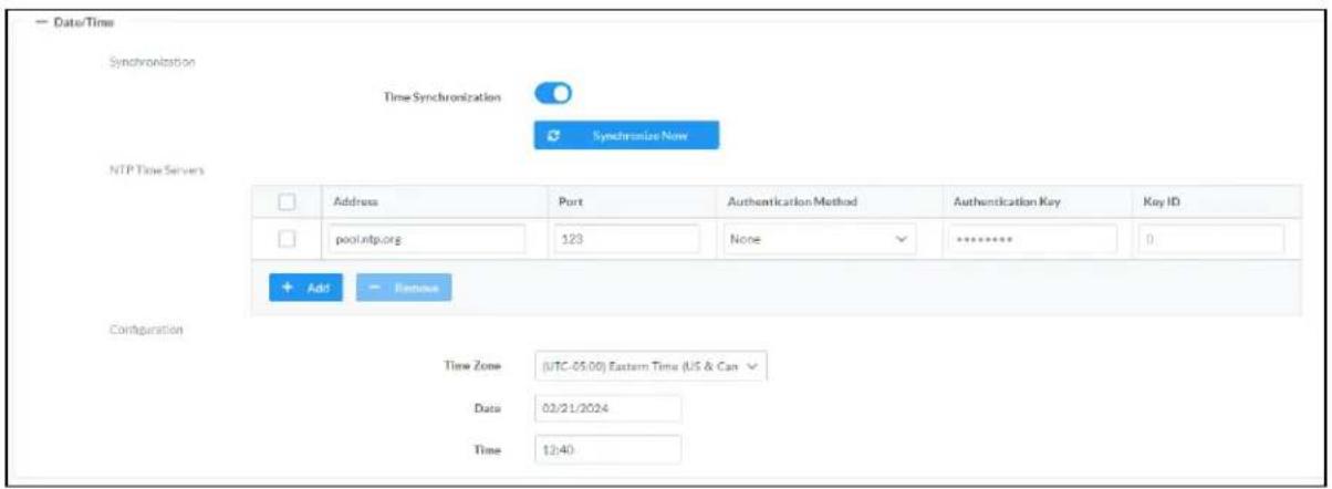
Time Synchronization
- Set the Time Synchronization toggle to the right position to enable or left position to disable time synchronization. By default, time synchronization is enabled.
- In the NTP Time Servers table, enter the URL of a NTP (Network Time Protocol) or SNTP (Simple Network Time Protocol) server. Up to three time servers can be added on a device.
- Click Synchronize Now to perform time synchronization between the device's internal clock and the time server.
Time Configuration
- Click on the Time Zone drop-down menu to select the applicable time zone.
- In the Date field, enter the current date.
- In the Time (24hr Format) field, enter the current time in 24-hour format.
Click the Save Changes button to save the settings.
Click Revert from the Actions drop-down menu to revert to the previous settings without saving.
Auto Update
The DM-NAX-BTIO-1G can automatically check for and install firmware updates at scheduled intervals via the Auto Update feature.

- Set the Auto Update toggle to the right position to enable Auto Update.
- Define the URL to download the updates by doing either of the following:
a. Use the default URL to download the updates from the Crestron server.
b. Use a custom URL. Set the Custom URL toggle to the right position to enable a custom URL. In the Custom URL Path text box, enter the path to a custom manifest file in the F' or SFTP URL format. Use the Crestron Auto Update Tool to generate a custom manifest file, then store the file on an FTP (File Transfer Protocol) or SFTP (Secure File Transfer Protocol) server.
- Set a schedule for the automatic firmware update by doing either of the following:
a. Select the desired Day of Week and Time of Day (24-hour format) values.
b. Set the Poll Interval by entering a value from 60 to 65535 minutes. A value of 0 disables the Poll Interval.
- Click Save Changes.
Clicking Update Now causes the device to check for a firmware update immediately. If a schedule was set in step 4 above, that schedule still remains in effect.
Network
The Network tab contains network-related settings for the DM-NAX-BTIO-1G, including the Hostname, Domain, Primary Static DNS, and Secondary Static DNS.
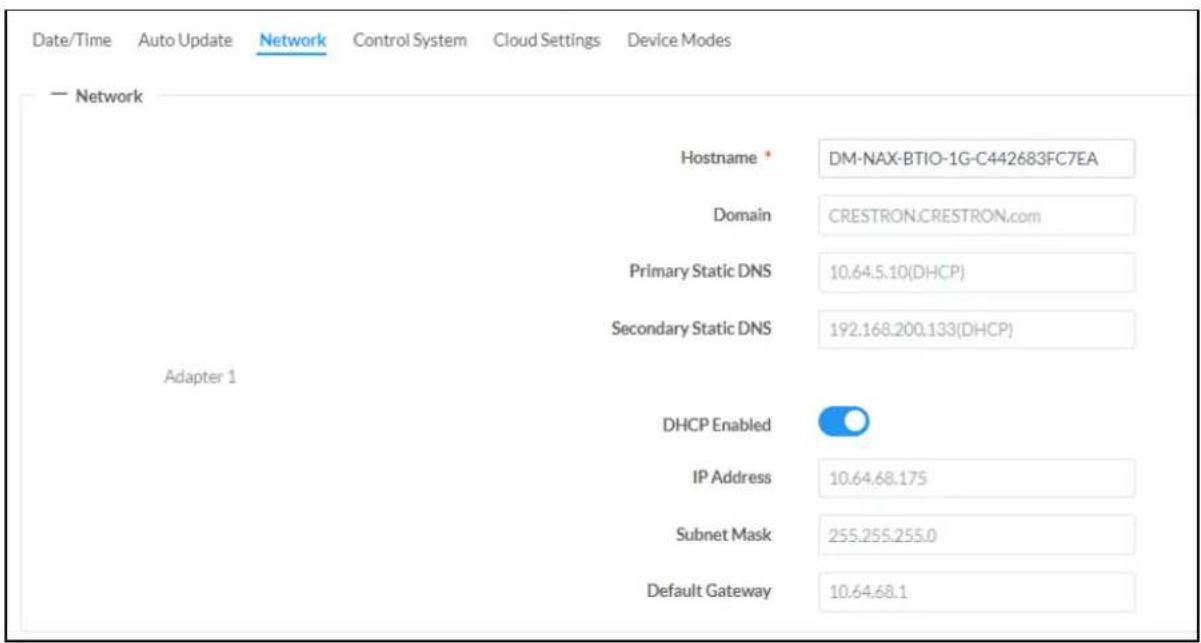
NOTE: By default, the hostname of the DM-NAX-BTIO-1G consists of the model name followed by the MAC address of the device. For example, DM-NAX-BTIO-1G-00107FB58088.
Adapter 1
The Adapter 1 subheading contains settings for DHCP, IP Address, Subnet Mask, and Default Gateway of Ethernet adapter 1 on the rear panel of the device.
NOTE: DM NAX devices' internal processes use IP addresses in the 10x10 range. This IP range should be avoided when addressing DM NAX devices to prevent conflicts.
Set the DHCP toggle to enabled (right) or disabled (left) to specify whether the IP address of the DM-NAX-BTIO-1G is to be assigned by a DHCP (Dynamic Host Configuration Protocol) server.
- Enabled: When DHCP is enabled (default setting), the IP address of the DM-NAX-BTIO-1G is automatically assigned by a DHCP server on the local area network (LAN).
-
Disabled: When DHCP is disabled, manually enter information in the following fields:
-
Primary Static DNS: Enter a primary DNS IP address.
Secondary Static DNS: Enter a secondary DNS IP address. - IP Address: Enter a unique IP address for the DM-NAX-BTIO-1G.
- Subnet Mask: Enter the subnet mask that is set on the network.
Default Gateway: Enter the IP address that is to be used as the network's gateway.
To save any new network entries, click Save Changes.
Control System
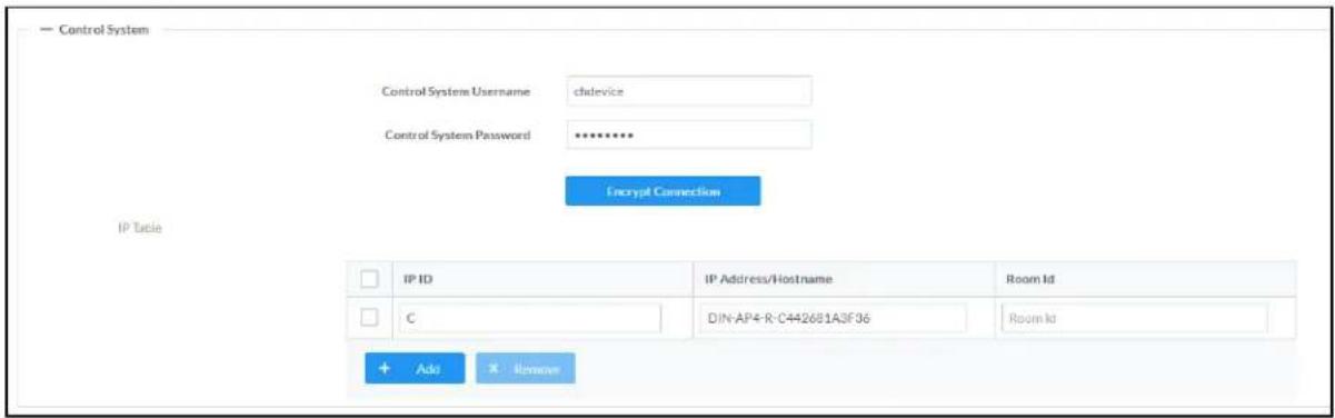
- Click the Encrypt Connection button to navigate to the Security tab to configure encryption settings.
- Enter the username in the Control System Username field.
- Enter the password in the Control System Password field.
- Enter the Room ID in the Room ID field.
- Enter the IP ID of the DM-NAX-BTIO-1G in the IP ID field.
- Enter the IP address or hostname of the control system in the IP Address/Hostname field.
- Click the Save Changes button to save the new entries. The Control System Save message box appears, indicating that the control system settings were saved successfully. Click the Revert button to revert to the previous settings without saving.
Cloud Settings

Set the Cloud Settings toggle to enabled (right) or disabled (left) to specify whether the DM-NAX-BTIO-1G can communicate with the XiO Cloud® platform.
Device Modes
Use the Device Modes tab to configure the Application Mode of the DM-NAX-BTIO-1G.
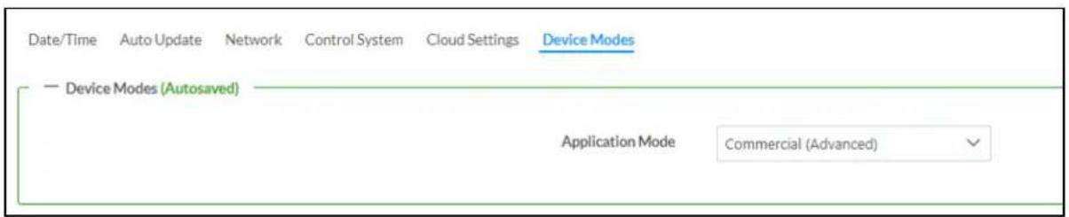
The Application Mode determines which options and controls are available.
- Select Residential (Standard) or Commercial (Advanced). A Reboot confirmation message box appears.

- Click Yes, Reboot Now to reboot the device into the selected mode. The Reboot message box appears.
- Wait for the device reboot to complete before attempting to reconnect to the device.
By default, the DM-NAX-BTIO-1G is set to Commercial (Advanced) mode.
Commissioning
The Commissioning section provides a quick way to automatically assign multicast addresses to the device's internal audio-over-IP stream transmitters.

Click Assign Addresses to give each DM NAX transmitter in the DM-NAX-BTIO-1G a unique multicast address beginning with the specified Starting Multicast Address. The valid range for Starting Multicast Address is 239.8.0.0 to 239.255.255.254.
NOTE: This will begin transmitting multicast traffic on your network, refer to the DM NAX Audio-over-IP System Design Guide document for details.
Bluetooth Settings
The Bluetooth section provides settings for the internal Bluetooth radio of the DM-NAX-BTIO-1G. These settings are divided up into two tabs, labeled Main and Advanced.
Main Bluetooth Settings

To configure the settings on the Main tab of the Bluetooth settings section:
- Enter a custom name for the DM-NAX-BTIO-1G in the Bluetooth Name text field. This is the narr that will be displayed on source devices (such as smartphones) that discover the DM-NAX-BTIO-1G as a casting destination.
- Set the Bluetooth Enable toggle to the right to allow Bluetooth wireless audio casting to the DM-NAX-BTIO-1G. Set the Bluetooth Enable toggle to the left to disable Bluetooth wireless audio.
NOTE: While Bluetooth audio is disabled on the device, some applications that scan for Bluetooth devices may still be able to detect the DM-NAX-BTIO-1G. These applications will not be able to connect to the DM-NAX-BTIO-1G or cast audio to it while Bluetooth audio is disabled.
- Set the Pairing Active toggle to the right to enable pairing mode, allowing Bluetooth devices to pair to the DM-NAX-BTIO-1G. Set the Pairing Active toggle to the left to disable pairing mode.
-
The Paired Devices table displays the name and status of all remembered Bluetooth devices that were previously paired with the DM-NAX-BTIO-1G.
-
The DM-NAX-BTIO-1G can remember up to seven previously paired devices.
- Only one paired Bluetooth device can have a Connected status at a time. All other paired devices will display a Disconnected status. The Connected status indicates which device is currently able to actively cast media to the wall plate.
- To disconnect a connected device, click the button.
To forget a remembered device from the Paired Devices table, click the button.
Advanced Bluetooth Settings

To configure the settings on the Advanced tab of the Bluetooth settings section:
- Select a Connection Management option from the drop-down.
In Interrupt mode, remembered paired devices can reconnect to the DM-NAX-BTIO-1G from their Bluetooth connections list, and will interrupt any currently playing audio. The most recent casting device to select the DM-NAX-BTIO-1G from its Bluetooth list will show a Connected status in the Paired Devices table, and all other devices will revert to Disconnected.
In Exclusive mode, remembered paired devices cannot be reconnected to the DM-NAX-BTIO-1G from their Bluetooth connections list until the currently Connected device is disconnected. The device that is listed as Connected in the Paired Devices table will remain as the Connected device until it is disconnected by programming, from the web interface, or by the casting device itself.
- TransientExclusive mode is the same as Exclusive mode, with the added behavior that the DM-NAX-BTIO-1G will forget the currently connected device once it is disconnected.
- Select a Reconnect Behavior option from the drop-down.
- Manual reconnection means that any time the Bluetooth casting device is disconnected from the DM-NAX-BTIO-1G, it can only be reconnected by selecting the casting device from the DM NAX device's list of paired devices.
Automatic reconnection means that any remembered paired Bluetooth casting device will reconnect to the DM-NAX-BTIO-1G when it is within the wireless range of the DM NAX device.
- Click the Paired Device Options button to open a Paired Device Options window. Select a command from the drop-down menu, then click the Send button to issue the command to the DM NAX device.
- Release All Paired Devices will disconnect all currently paired devices from the DM-NAX-BTIO-1G.
- Release Inactive Paired Devices will disconnect any paired device that is not actively playing any media.
- Forget All Paired Devices will delete all currently paired devices from the Paired Devices table of the DM-NAX-BTIO-1G.
- Forget Inactive Paired Devices will disconnect and forget any paired device that is not actively playing any media.
-
Forget Connected Devices will disconnect and forget only the current Connected device.
-
Set the Pairing Code Enabled toggle to the right to enable the pairing code. When this is enabled, a pairing code string will populate on both the casting device and the OLED display of the DM-NAX-BTIO-1G during pairing. Confirm that the code matches on each device to complete the pairing process. Set the toggle to the left to disable the pairing code.
- Set the Connect Chime Enable toggle to the right to hear a short chime whenever a device successfully pairs to the DM-NAX-BTIO-1G. This chime is played back on the Bluetooth audio input path. Any outputs that receive the Bluetooth audio input signal will receive the chime audio. Set the Connect Chime Enable toggle to the left to disable the connect chime.
- Set the Disconnect Chime Enable toggle to the right to hear a short chime whenever a device is disconnected from the DM-NAX-BTIO-1G. This chime is played back on the Bluetooth audio input path. Any outputs that receive the Bluetooth audio input signal will receive the chime audio. Set the Disconnect Chime Enable toggle to the left to disable the disconnect chime.
Display

The Display section contains settings that affect the front panel OLED display of the DM-NAX-BTIO-1G.
• To adjust the display brightness:
- Click the % arrows to increase or decrease the brightness. Values range from 0 to 100%, adjustable in increments of 1%.
- Manually enter a percentage value in the Brightness text field.
• To adjust the display standby timeout:
- Click the Minutes arrows to increase or decrease the brightness. The default timeout value is one minute.
- Manually enter a value in the Standby Timeout text field.
- Set the Button Lockout toggle to the right to lock out the front panel buttons on the DM-NAX-BTIO-1G. Set the Button Lockout toggle to the left to disable the lockout.
Output Channels
The Zones section contains the Volume and Mute settings for all zone outputs of the device, as well as an Edit option for more advanced settings within each zone.

Signal Presence indicates whether or not an audio signal is detected in that zone.
Signal Level indicates if the signal is Clipping or Nominal (non-clipping).
- Nominal: The signal level is within normal operating bounds and below the clipping threshold.
- Clipping: The signal level is clipping or above the -3 dB warning threshold and in danger of clipping.
Give each zone a friendly name using the Name column of the Zones table. If the device is paired with a control system, these names may be overwritten by the control system's program.
To configure the zone volume, do one of the following:
- Move the Volume slider up to increase or down to decrease the zone volume.
- Click the % arrows to increase or decrease the zone volume. Values range from 0 to 100%, adjustable in increments of 1%.
- Manually enter a value in the Volume field.
To mute all audio output from a zone, click its respective Mute button. To unmute the zone, click the Muted button.
Click Edit to view additional Zone and Output options.
Zone Settings
To configure the settings for an output channel, click the Edit button. The Edit Zone window appears.

Zone
Click Zone to access the settings for Delay.

Delay

To set the delay, do one of the following:
- Move the Delay Time(ms) slider to the right to increase or to the left to decrease the delay time.
- Click the ms arrows to increase or decrease the delay. Values range from 0 ms to 85 ms, adjustable in increments of 1 ms.
- Manually enter a value in the Delay Time(ms) field.
NOTE: The Delay feature is only available on the line level output channels.
Output
Click Output to access the settings for Minimum/Maximum Volume and Signal.

Minimum/Maximum Volume
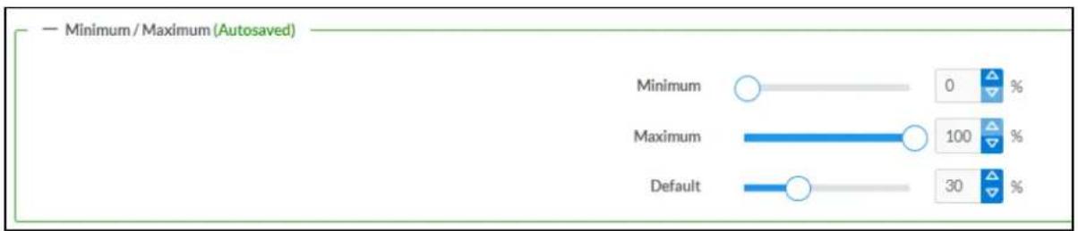
-
To set the minimum volume of the zone, do one of the following:
-
Move the Minimum slider to the right to increase or to the left to decrease the minimum volume.
- Click the % arrows to increase or decrease the minimum volume. Values range from 0 to 50%, adjustable in increments of 1%.
-
Manually enter a value in the Minimum field.
-
To set the maximum volume of the zone, do one of the following:
- Move the Maximum slider to the right to increase or to the left to decrease the maximum volume.
- Click the % arrows to increase or decrease the maximum volume. Values range from 70 to 100%, adjustable in increments of 1%.
- Manually enter a value in the Maximum field.
NOTE: When a Minimum and Maximum volume are set, the 1-100% range represented by the Zone and Default volume controls are scaled to the range set. For example, if a Minimum of 10% and a Maximum of 80% are set for a zone, the 1-100% range of the Zone volume control is scaled to the 10%-80% range set as the Minimum and Maximum.
- To set the default volume of the zone, do one of the following:
- Move the Default slider to the right to increase or to the left to decrease the default volume.
- Click the % arrows to increase or decrease the default volume. Values range from 0 to 50% adjustable in increments of 1%.
- Manually enter a value in the Default field.
NOTE: The Default volume is applied as the Zone volume any time the zone receives a source route and no source was previously routed to that zone.
Signal

The Signal section is a read-only field that displays the Signal and Clipping status of the zone output.
- If an output signal is present but not clipping, Signal will display Present in green and Clipping will display None in green.
- If an output signal is present and clipping, Signal will display Present in green and Clipping will display Present in red.
- If no output signal is detected, Signal will display Not Present in red and Clipping will display None in green.
Input Channels
The Input Channels section is used to configure the Name, Compensation, and Mute attributes of the audio inputs of the DM-NAX-BTIO-1G.
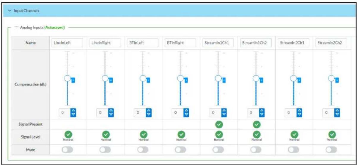
Configure Inputs
- If needed, enter a friendly name for each input in its Name field.
-
To set a level compensation adjustment for a given input, do one of the following:
-
Move the Compensation slider up to increase or down to decrease the level compensation. Compensation increases or decreases the level of the incoming audio signal on any of the physical inputs on the device's rear panel.
- Click the db arrows to increase or decrease the compensation. Values range from -10 dB to 10 dB, adjustable in increments of 1 dB.
-
Manually enter a value in the Compensation field.
-
To mute the signal from the corresponding input, set the Mute toggle to the right. To disable the mute, set the Mute toggle to the left. By default, Mute is disabled.
Monitor the device's input signals using the text indicators in the Signal Present and Clipping Detected columns:
- Signal Presence indicates whether or not a signal is detected in that zone.
- Clipping Detected indicates if the signal is Clipping or Nominal (non-clipping).
DM NAX Streams
The local inputs of the DM-NAX-BTIO-1G can be made available as DM NAX audio-over-IP streams. Two network stream transmitters are available on the device. One transmitter will encode the local unbalanced line level input, and the other will encode the Bluetooth input audio.
Click NAX Streams to expand the tab and display the following information.

- Device is Master PTP Clock Source indicates whether the DM NAX device's PTP clock is the master clock on the network. Yes will be displayed in green when the local DM-NAX-BTIO-1G's clock is the PTP master clock and No will be displayed in red when another PTP clock on the network is operating as the master clock.
- Master Clock Status displays the Master Clock ID of the device on the network that is currently acting as the master clock.
- PTP Priority: This sets the priority of the local DM NAX device's PTP clock relative to other clocks on the network. The default setting is 254 (one increment higher than the lowest possible value) so that the DM-NAX-BTIO-1G will only operate as clock master if no other PTP master is present on the network. Valid values range from 1 to 255.
Configure Transmitters
To configure the DM NAX transmit stream, do the following.
- Enter a valid multicast address in the NAX Stream Address field.
- Enter a name in the NAX Stream Name field by which the stream can be identified. This stream name is associated with the DM NAX stream's multicast address by other DM NAX or AES67 devices, like a device hostname that resolves to a given IP address.
- Status indicates whether a stream is transmitting or not. When the stream has started or stopped, the Status column will update accordingly.
- Click the configure button (⚙️) in the Actions column. The Configure dialog appears:

-
Set the Auto Initiation toggle to the right position to enable auto initiation. Set the toggle to the left position to disable auto initiation.
-
If Auto Initiation is enabled for a given stream, the stream will begin transmitting automatically and will be available as a multicast stream on your network at the specified multicast address.
-
If Auto Initiation is disabled for the input, the stream will not begin transmitting until it is manually initiated.
-
To set the port number, do one of the following:
-
Click the arrows to increase or decrease the port number by increments of 1.
-
Manually enter a port number in the Port field. The default port number for DM NAX streams is 5004.
-
Click OK to save or click Cancel to cancel the changes.
Configure Receivers
-
Enter the multicast address of a transmitting stream in the Requested Stream Address field to subscribe the receiver to the stream.
-
Click the configure button (💡) in the Actions column. The Configure dialog appears:

-
Set the Auto Initiation toggle to the right position to enable auto initiation. Set the toggle to the left position to disable auto initiation.
-
If Auto Initiation is enabled, the stream will begin automatically when the receiver subscribes to the transmitter.
-
If Auto Initiation is disabled, the stream will not begin until it is manually initiated.
-
To set the port number, do one of the following:
-
Click the arrows to increase or decrease the port number by increments of 1.
-
Manually enter a port number in the Port field. The default port number is 5004.
-
Click OK to save or click Cancel to cancel the changes.
Mixing
The Mixing matrix is used to route a local input or AES67 stream to an output on the DM-NAX-BTIO-1G.
NOTE: To receive an AES67 stream from Dante devices, see OLH 1001151.
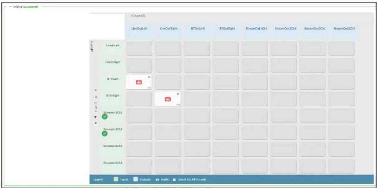
To route inputs to outputs on the device:
- Click the cells corresponding to the desired output that are to be paired for routing. Once a route is made, appears. The input that you have selected for a given row will route to the output corresponding to that row in the matrix.
- Use the arrows (or) at the left of the matrix to change pages to view all available inputs.
• To break a given route click or✗
Each output can have any number of inputs routed to it. To adjust the mix setting for a route, click the dB value of the cell, then do one of the following:
- Move the slider up to increase or down to decrease the mix level.
- Click the arrows to increase or decrease the mix level.
- Manually enter a value in the field.
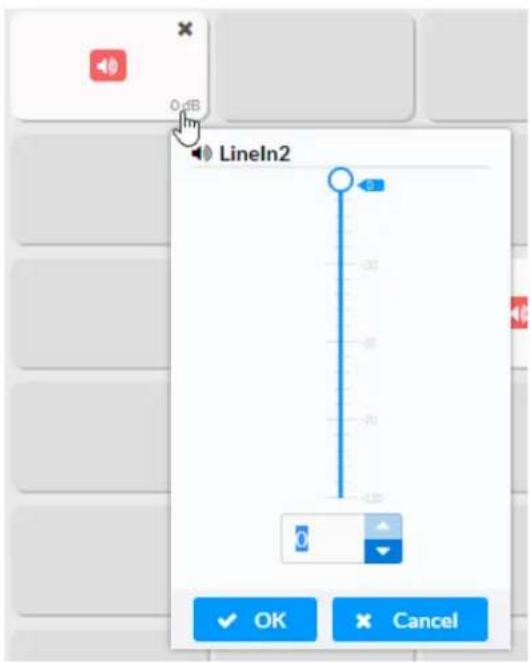
Residential Mode
This section provides the following information:
• System Setup on page 613
• Commissioning on page 618
- Bluetooth on page 619
• Display on page 621
• Output Channels on page 622
- Inputs on page 626
• NAX Streams on page 627
- Routing on page 629
DM-NAX-BTIO-1G-C442683FC7EA
Status
Settings
Security
802.1x Configuration
System Setup
Commissioning
Bluetooth
Display
Output Channels
Input Channels
NAX Streams
Mixing
System Setup
The System Setup section displays information about the Date/Time, Auto Update, Network, Control System, Cloud Settings, and Device Modes.
Date/Time
Use the Date/Time section to configure the date and time settings of the DM-NAX-BTIO-1G.

Time Synchronization
- Set the Time Synchronization toggle to the right position to enable or left position to disable time synchronization. By default, time synchronization is enabled.
- In the NTP Time Servers table, enter the URL of a NTP (Network Time Protocol) or SNTP (Simple Network Time Protocol) server. Up to three time servers can be added on a device.
- Click Synchronize Now to perform time synchronization between the device's internal clock and the time server.
Time Configuration
- Click on the Time Zone drop-down menu to select the applicable time zone.
- In the Date field, enter the current date.
- In the Time (24hr Format) field, enter the current time in 24-hour format.
Click the Save Changes button to save the settings.
Click Revert from the Actions drop-down menu to revert to the previous settings without saving.
Auto Update
The DM-NAX-BTIO-1G can automatically check for and install firmware updates at scheduled intervals via the Auto Update feature.
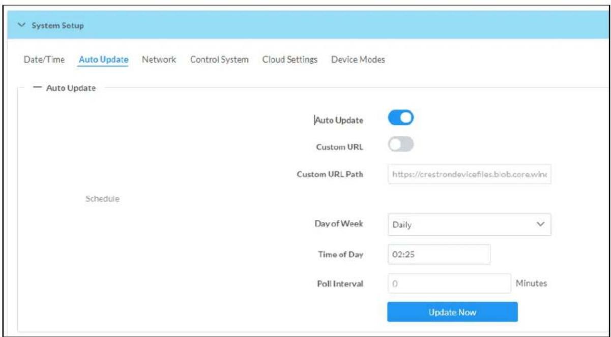
- Set the Auto Update toggle to the right position to enable Auto Update.
- Define the URL to download the updates by doing either of the following:
a. Use the default URL to download the updates from the Crestron server.
b. Use a custom URL. Set the Custom URL toggle to the right position to enable a custom URL. In the Custom URL Path text box, enter the path to a custom manifest file in the F' or SFTP URL format. Use the Crestron Auto Update Tool to generate a custom manifest file, then store the file on an FTP (File Transfer Protocol) or SFTP (Secure File Transfer Protocol) server.
- Set a schedule for the automatic firmware update by doing either of the following:
a. Select the desired Day of Week and Time of Day (24-hour format) values.
b. Set the Poll Interval by entering a value from 60 to 65535 minutes. A value of 0 disables the Poll Interval.
- Click Save Changes.
Clicking Update Now causes the device to check for a firmware update immediately. If a schedule was set in step 4 above, that schedule still remains in effect.
Network
The Network section contains network-related settings for the DM-NAX-BTIO-1G, including the Hostname, Domain, Primary Static DNS, and Secondary Static DNS.

NOTE: By default, the host name of the DM-NAX-BTIO-1G consists of the model name followed by the MAC address of the device. For example, DM-NAX-BTIO-1G-00107FB58088.
Adapter 1
The Adapter 1 subheading contains settings for DHCP, IP Address, Subnet Mask, and Default Gateway of Ethernet adapter 1 on the rear panel of the device.
NOTE: DM NAX devices' internal processes use IP addresses in the 10x10 range. This IP range should be avoided when addressing DM NAX devices to prevent conflicts.
Set the DHCP toggle to enabled (right) or disabled (left) to specify whether the IP address of the DM-NAX-BTIO-1G is to be assigned by a DHCP (Dynamic Host Configuration Protocol) server.
- Enabled: When DHCP is enabled (default setting), the IP address of the DM-NAX-BTIO-1G is automatically assigned by a DHCP server on the local area network (LAN).
-
Disabled: When DHCP is disabled, manually enter information in the following fields:
-
Primary Static DNS: Enter a primary DNS IP address.
Secondary Static DNS: Enter a secondary DNS IP address. - IP Address: Enter a unique IP address for the DM-NAX-BTIO-1G.
- Subnet Mask: Enter the subnet mask that is set on the network.
Default Gateway: Enter the IP address that is to be used as the network's gateway.
To save any new network entries, click Save Changes.
Control System
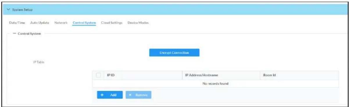
- Click the Encrypt Connection button to navigate to the Security tab to configure encryption settings.
- Enter the username in the Control System Username field.
- Enter the password in the Control System Password field.
- Enter the Room ID in the Room ID field.
- Enter the IP ID of the DM-NAX-BTIO-1G in the IP ID field.
- Enter the IP address or hostname of the control system in the IP Address/Hostname field.
- Click the Save Changes button to save the new entries. The Control System Save message box appears, indicating that the control system settings were saved successfully. Click the Revert button to revert to the previous settings without saving.
Cloud Settings

Set the Cloud Settings toggle to enabled (right) or disabled (left) to specify whether the DM-NAX-BTIO-1G can communicate with the XiO Cloud® platform.
Device Modes
Use the Device Modes section to configure the Application Mode.

- Application Mode: The Application Mode determines which options and controls are available.
Select Residential (Standard) or Commercial (Advanced). A Reboot confirmation message box appears.
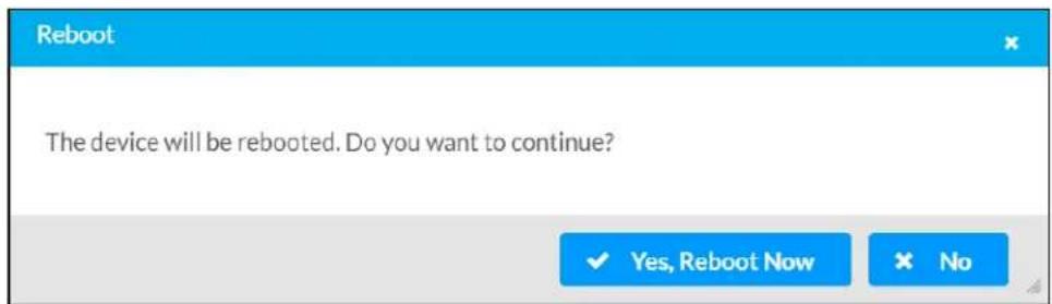
- Click Yes, Reboot Now to reboot the device into the selected mode. The Reboot message box appears.
- Wait for the device reboot to complete before attempting to reconnect to the device.
Commissioning
The Commissioning section provides a quick way to automatically assign multicast addresses to the device's internal audio-over-IP stream transmitters.
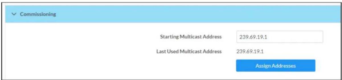
Click Assign Addresses to give each DM NAX transmitter in the DM-NAX-BTIO-1G a unique multicast address beginning with the specified Starting Multicast Address. The valid range for Starting Multicast Address is 239.8.0.0 to 239.127.255.254.
NOTE: This will begin transmitting multicast traffic on your network, refer to the General Network Requirements document for details.
Bluetooth
The Bluetooth section provides settings for the internal Bluetooth radio of the DM-NAX-BTIO-1G. These settings are divided up into two tabs, labeled Main and Advanced.
Main Bluetooth Settings
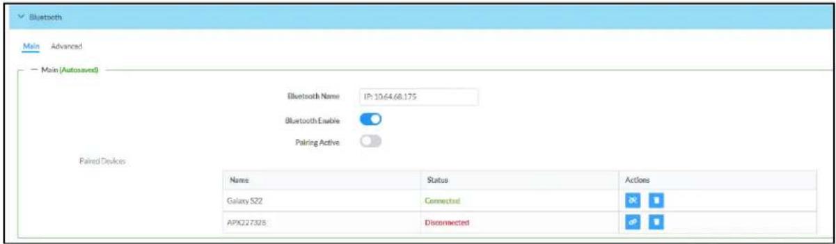
To configure the settings on the Main tab of the Bluetooth settings section:
- Enter a custom name for the DM-NAX-BTIO-1G in the Bluetooth Name text field. This is the narr that will be displayed on source devices (such as smartphones) that discover the DM-NAX-BTIO-1G as a casting destination.
- Set the Bluetooth Enable toggle to the right to allow Bluetooth wireless audio casting to the DM-NAX-BTIO-1G. Set the Bluetooth Enable toggle to the left to disable Bluetooth wireless audio.
NOTE: While Bluetooth audio is disabled on the device, some applications that scan for Bluetooth devices may still be able to detect the DM-NAX-BTIO-1G. These devices will not be able to connect to the DM-NAX-BTIO-1G or cast audio to it while Bluetooth audio is disabled.
- Set the Pairing Active toggle to the right to enable pairing mode, allowing Bluetooth devices to pair to the DM-NAX-BTIO-1G. Set the Pairing Active toggle to the left to disable pairing mode.
- The Paired Devices table displays the name and status of all remembered Bluetooth devices that have previously paired with the DM-NAX-BTIO-1G.
The DM-NAX-BTIO-1G can remember up to seven previously paired devices.
- Only one paired Bluetooth device can have a Connected at a time. All other paired devices will display a Disconnected status.
To disconnect a connected device, click the button.
To forget a remembered device from the Paired Devices table, click the button.
Advanced Bluetooth Settings

To configure the settings on the Advanced tab of the Bluetooth settings section:
- Select a Connection Management option from the drop-down.
- Interrupt connection management means that remembered paired devices can reconnect to the DM-NAX-BTIO-1G from their Bluetooth connections list, and will interrupt any currently playing audio when they do so. The most recent device to select the DM-NAX-BTIO-1G from its Bluetooth list will have a Connected status in the Paired Devices table, and all other devices will revert to Disconnected.
Exclusive connection management means that remembered paired devices can reconnect to the DM-NAX-BTIO-1G from their Bluetooth connections list, but they will not be able to play audio until the currently Connected device is disconnected. Whichever device was already listed as Connected in the Paired Devices table will remain as the Connected device until it is disconnected by programming, from the web interface, or by the casting device itself.
- Select a Reconnect Behavior option from the drop-down.
- Manual reconnection means that the Bluetooth casting device must be reconnected to the DM-NAX-BTIO-1G by selecting the DM NAX device from the casting device's Bluetooth menu after a casting session ends or the device goes out of range of the DM NAX device.
Automatic reconnection means that the Bluetooth casting device reconnects to the DM-NAX-BTIO-1G when it re-enters the wireless range of the DM NAX device.
- Click the Paired Device Options button to open a Paired Device Options window with a drop-down menu and a Send button. Select a command from the drop-down menu, then click the Send button to issue the command to the DM NAX device.
- Release All Paired Devices will disconnect all currently paired devices from the DM-NAX-BTIO-1G.
- Release Inactive Paired Devices will disconnect any paired device that is out of range of the DM-NAX-BTIO-1G.
- Forget All Paired Devices will delete all currently paired devices from the Paired Devices table of the DM-NAX-BTIO-1G.
- Forget Inactive Paired Devices will delete any paired devices from the Paired Devices table that are out of range of the DM-NAX-BTIO-1G.
-
Forget Connected Devices will delete any device from the Paired Devices table that has a Connected status.
-
Pairing Code Enabled is reserved for future use.
- Set the Connect Chime Enable toggle to the right to hear a short chime audio file whenever a device successfully pairs to the DM-NAX-BTIO-1G. This chime is played back on the Bluetooth audio input path. Any outputs that receive the Bluetooth audio input signal will receive the chime audio. Set the Connect Chime Enable toggle to the left to disable the connect chime.
- Set the Disconnect Chime Enable toggle to the right to hear a short chime audio file whenever device is disconnected from the DM-NAX-BTIO-1G. This chime is played back on the Bluetooth audio input path. Any outputs that receive the Bluetooth audio input signal will receive the chime audio. Set the Disconnect Chime Enable toggle to the left to disable the disconnect chime.
Display

The Display section contains settings that affect the front panel OLED display of the DM-NAX-BTIO-1G.
• To adjust the display brightness:
- Click the % arrows to increase or decrease the brightness. Values range from 0 to 100%, adjustable in increments of 1%.
- Manually enter a percentage value in the Brightness text field.
• To adjust the display standby timeout:
- Click the Minutes arrows to increase or decrease the brightness. The default timeout value is one minute.
- Manually enter a value in the Standby Timeout text field.
- Set the Button Lockout toggle to the right to lock out the front panel buttons on the DM-NAX-BTIO-1G. Set the Button Lockout toggle to the left to disable the lockout.
Output Channels
The Zones section contains the Volume and Mute settings for all zone outputs of the device, as well as a Configure option for more advanced settings within each zone.
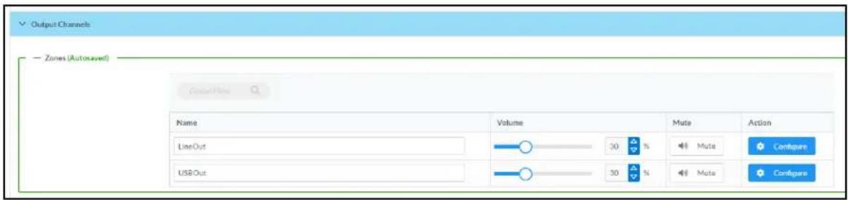
Give each zone a friendly name using the Name column of the Zones table. If the device is paired with a control system, these names may be overwritten by the control system's program.
To configure the zone volume, do one of the following:
- Move the Volume slider to the right to increase or to the left to decrease the zone volume.
- Click the % arrows to increase or decrease the zone volume. Values range from 0 to 100%, adjustable in increments of 1%.
- Manually enter a value in the Volume field.
To mute all audio output from a zone, click its respective Mute button. To unmute the zone, click the Muted button.
Zone Settings
To configure zone settings, click the Configure button (Configure). The Edit Zone window appears.
Zone
Click Zone to access the settings for Balance and Delay.

Balance
To adjust the left/right balance of the stereo output signal, do one of the following:
- Move the Balance slider to the right to shift the stereo balance to the right channel or to the left to shift the balance to the left.
- Click the arrows to adjust the balance left or right. The up arrow shifts the balance to the right while the down arrow shifts the balance to the left.
- Manually enter a value in the Balance field. Values range from -50 to 50, adjustable in increments of 1. Positive values shift the balance to the right while negative values shift the balance to the left.
Delay
To set the delay, do one of the following:
- Move the Delay Time(ms) slider to the right to increase or to the left to decrease the delay time.
- Click the ms arrows to increase or decrease the delay. Values range from 0 ms to 85 ms, adjustable in increments of 1 ms.
- Manually enter a value in the Delay Time(ms) field.
NOTE: The Delay feature is only available on the line level output channels.
Output
Click Output to access the settings for Minimum/Maximum Volume, Stereo/Mono, and Signal.

Minimum/Maximum Volume

-
To set the minimum volume of the zone, do one of the following:
-
Move the Minimum slider to the right to increase or to the left to decrease the minimum volume.
- Click the % arrows to increase or decrease the minimum volume. Values range from 0 to 50%, adjustable in increments of 1%.
-
Manually enter a value in the Minimum field.
-
To set the maximum volume of the zone, do one of the following:
-
Move the Maximum slider to the right to increase or to the left to decrease the maximum volume.
- Click the % arrows to increase or decrease the maximum volume. Values range from 70 to 100%, adjustable in increments of 1%.
- Manually enter a value in the Maximum field.
NOTE: When a Minimum and Maximum volume are set, the 1-100% range represented by the Zone and Default volume controls are scaled to the range set. For example, if a Minimum of 10% and a Maximum of 80% are set for a zone, the 1-100% range of the Zone volume control is scaled to the 10%-80% range set as the Minimum and Maximum.
-
To set the default volume of the zone, do one of the following:
-
Move the Default slider to the right to increase or to the left to decrease the default volume.
- Click the % arrows to increase or decrease the default volume. Values range from 0 to 50% adjustable in increments of 1%.
- Manually enter a value in the Default field.
NOTE: The Default volume is applied as the Zone volume any time the zone receives a source route and no source was previously routed to that zone.
Stereo/Mono

Select either Stereo or Mono from the Stereo/Mono radio buttons. If Stereo is selected, both output channels can have independent audio content. If Mono is selected, both output channels receive the same audio content.
Signal

The Signal section is a read-only field that displays the Signal and Clipping status of the zone output.
- If an output signal is present but not clipping, Signal will display Present in green and Clipping will display None in green.
- If an output signal is present and clipping, Signal will display Present in green and Clipping will display Present in red.
- If no output signal is detected, Signal will display Not Present in red and Clipping will display None in green.
Click Done to return to the Settings tab of the web user interface.
Inputs
The Inputs section is used to configure the Name, Compensation, and Mute attributes of the available analog, digital, and media streaming inputs on the DM-NAX-BTIO-1G.

Configure Inputs
- If needed, enter a friendly name for each input in its Name field.
-
To set a level compensation adjustment for a given input, do one of the following:
-
Move the Compensation slider up to increase or down to decrease the level compensation. Compensation increases or decreases the level of the incoming audio signal on any of the physical inputs on the device's rear panel.
- Click the db arrows to increase or decrease the compensation. Values range from -10 dB to 10 dB, adjustable in increments of 1 dB.
-
Manually enter a value in the Compensation field.
-
To mute the signal from the corresponding input, set the Mute toggle to the right. To disable the mute, set the Mute toggle to the left. By default, Mute is disabled.
Monitor the device's input signals using the text indicators in the Signal Present and Clipping Detected columns:
• Signal Presence indicates whether or not a signal is detected in that zone.
- Clipping Detected indicates if the signal is Clipping or Nominal (non-clipping).
NAX Streams
The two local inputs of the DM-NAX-BTIO-1G can be made available as DM NAX audio-over-IP streams.
Click NAX Streams to expand the tab and display the following information.
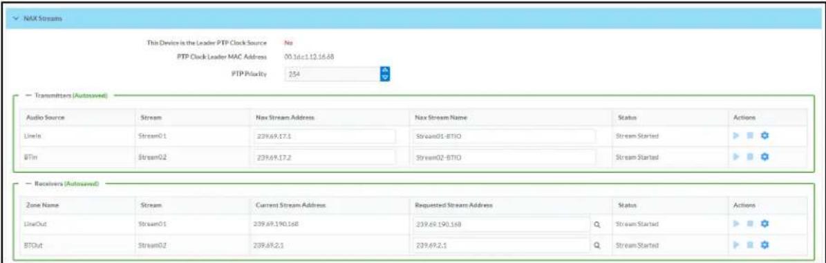
- Device is Master PTP Clock Source indicates whether the device is the master for PTP on the network. Yes will be displayed in green when the local DM-NAX-BTIO-1G is the PTP clock master and No will be displayed in red when another PTP clock on the network is operating as the master clock.
- Master Clock Status displays the Master Clock ID of the device on the network that acts as the Master Clock.
- PTP Priority: This sets the priority of the local DM NAX device's PTP clock relative to other clocks on the network. The default setting is 254 (one increment higher than the lowest possible value) so that the DM-NAX-BTIO-1G will only operate as clock master if no other PTP master is present on the network. Valid values range from 1 to 255.
Configure Transmitters
To configure a DM NAX transmit stream, do the following.
- Enter a valid multicast address in the NAX Stream Address field.
- Enter a name in the NAX Stream Name field by which the stream can be identified. This stream name is associated with the DM NAX stream's multicast address by other DM NAX or AES67 devices, like a device hostname that resolves to a given IP address.
- Status indicates whether a stream is transmitting or not. When the stream has started or stopped, the Status column will update accordingly.
- Click the configure button (✗) in the Actions column. The Configure dialog appears:

-
Set the Auto Initiation toggle to the right position to enable auto initiation. Set the toggle to the left position to disable auto initiation.
-
If Auto Initiation is enabled for a given stream, the stream will begin transmitting automatically and will be available as a multicast stream on your network at the specified multicast address.
-
If Auto Initiation is disabled for the input, the stream will not begin transmitting until it is manually initiated.
-
To set the port number, do one of the following:
-
Click the arrows to increase or decrease the port number by increments of 1.
-
Manually enter a port number in the Port field. The default port number for DM NAX streams is 5004.
-
Click OK to save or click Cancel to cancel the changes.
Configure Receivers
- Enter the multicast address of a transmitting stream in the Requested Stream Address field to subscribe the receiver to the stream.
- Click the configure button (💡) in the Actions column. The Configure dialog appears:

-
Set the Auto Initiation toggle to the right position to enable auto initiation. Set the toggle to the left position to disable auto initiation.
-
If Auto Initiation is enabled, the stream will begin automatically when the receiver subscribes to the transmitter.
-
If Auto Initiation is disabled, the stream will not begin until it is manually initiated.
-
To set the port number, do one of the following:
-
Click the arrows to increase or decrease the port number by increments of 1.
-
Manually enter a port number in the Port field. The default port number is 5004.
-
Click OK to save or click Cancel to cancel the changes.
Routing
The Routing section is used to route a local input or AES67 stream to a Zone on the DM-NAX-BTIO-1G.
NOTE: To receive an AES67 stream from Dante devices, see OLH 1001151.

To route an input to a zone, click the box in the routing matrix where the zone's row overlaps the corresponding input's column. Once a route is made, appears. To break a given route click or . To route a single input to all zones, click on the icon under the input's name.
Security
Click the Security tab to configure security for users and groups and to allow different levels of access to the DM-NAX-BTIO-1G functions. By default, security is disabled.

Select Encrypt and Validate, Encrypt, or OFF in the SSL Mode drop-down menu, to specify whether to use encryption. By default, SSL Mode is set to OFF.
Current User
Click the Current User tab to view read-only information or to change the password for the current user.
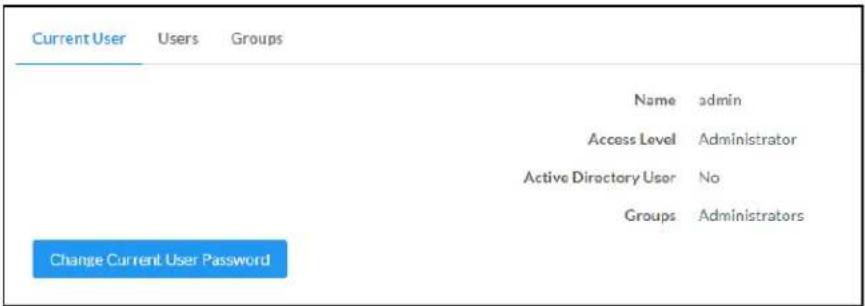
-
Click the Change Current User Password button to provide a new password for the current user.
-
In the Change Password dialog, enter the current password in the Current Password field, the new password in the Password field, and then re-enter the same new password in the Confirm Password field.

- Click OK to save or click Cancel to cancel the changes.
Users
Click the Users tab to view and edit user settings. The Users tab can be used to add or remove local and Active Directory users and preview information about users.
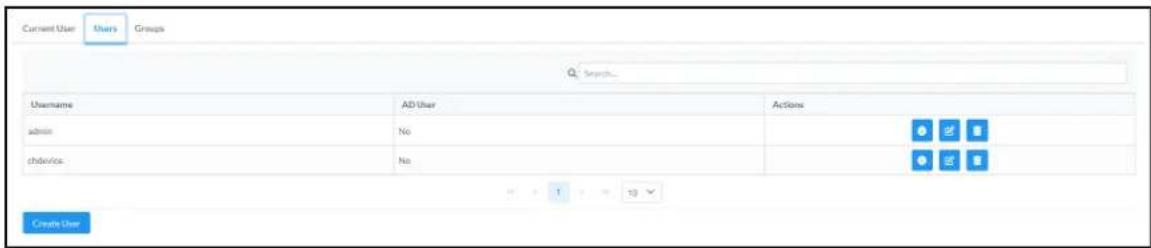
Use the Search Users field to enter search term(s) and display users that match the search criteria.
If users listed in the Users table span across multiple pages, navigate through the list of users by clicking a page number or by using the left or right arrows at the bottom of the Users pane to move forward or backward through the pages.
Each page can be set to display 5, 10, or 20 users by using the drop-down menu to the right of the navigation arrows.
Information about existing users is displayed in table format and the following details are provided for each user.
- Username: Displays the name of the user.
- AD User: Displays whether the user requires authentication using Active Directory.
Click the corresponding button in the Actions column to view detailed user information or to delete the user.
To create a new user, click the Create User button.
Create a New Local User
-
Click the Create User button in the User tab.
-
In the Create User dialog, enter the following:
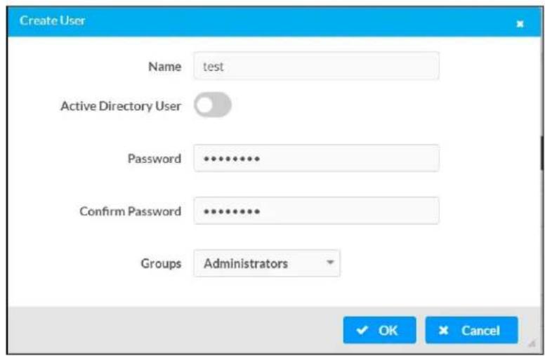
a. Enter a user name in the Name field. A valid user name can consist of alphanumeric characters (letters a-z, A-Z, numbers 0-9) and the underscore "_" character.
b. Enter a password in the Password field; re-enter the same password in the Confirm Password field.
c. Assign the access level by selecting one or more groups from the Groups drop-down list.
NOTE: Make sure that the Active Directory User toggle is disabled.
- Click OK to save or click Cancel to cancel the changes.
Add an Active Directory User
Users cannot be created or removed from the Active Directory server, but access can be granted to an existing user in the Active Directory server.
To grant access to an Active Directory user, you can either add the user to a local group on the DM-NAX-BTIO-1G, or add the Active Directory group(s) that they are a member of to the DM-NAX-BTIO-1G.
To add an Active Directory user.
- Click the Create User button.
- In the Create User dialog, enter the following.
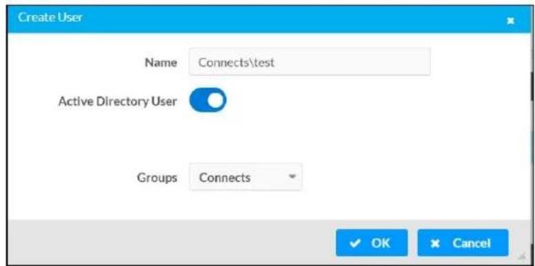
a. Enter a user name in the Name field in the format "Domain\UserName", for example "crestronlabs.com\JohnSmith". Valid user names can contain alphanumeric characters (letters a-z, A-Z, numbers 0-9) and the underscore "_" character.
b. Select one or more groups from the Groups drop-down list.
NOTE: Make sure that the Active Directory User toggle is set to enabled.
- Click OK to save or click Cancel to cancel the changes.
Delete User
Click the trashcan button (☐) in the Actions column to delete the user. Click Yes when prompted to delete the user or No to cancel the deletion.
After a user is removed from a group, they lose any access rights associated with that group. Note that the user account is not deleted by the delete user operation.
View User Details
Click the information button (0) in the Actions column to view information for the selected user. The User Details dialog displays the following information for the selected user.
- Name: Displays the name of the selected user.
• Active Directory User: Displays whether the user is an Active Directory user. - Group: Displays group(s) the selected user is part of.

Click OK to close the User Details dialog and to return to the Users tab.
Update User Details
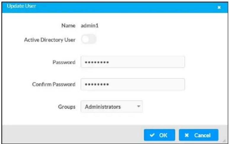
- Click the edit button() in the Actions column to update information for the selected user.
- Enter a password in the Password field; re-enter the same password in the Confirm Password field.
- Select one or more groups to assign the user to from the Groups drop-down list.
- Click OK to save or click Cancel to cancel the changes.
The Update User dialog also displays the following read-only information for the selected user.
• Name: Displays the name of the user.
• Active Directory User: Displays whether the user is an Active Directory user.
Groups
Click the Groups tab to view and edit group settings. The Groups tab can be used to add local and Active Directory groups, remove local and Active Directory groups, and preview information about a group.
Use the Search Groups field to enter search term(s) and display groups that match the search criteria.
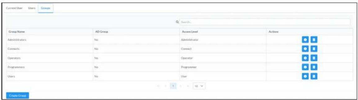
If groups listed in the Groups table span across multiple pages, navigate through the groups by clicking a page number or by using the left or right arrows at the bottom of the Groups pane to move forward or backward through the pages.
Additionally, each page can be set to display 5, 10, or 20 groups by using the drop-down menu to the right of the navigation arrows.
Existing groups are displayed in a table and the following information is provided for each group:
- Group Name: Displays the name of the group.
• AD Group: Displays whether the group requires authentication using Active Directory. - Access Level: Displays the predefined access level assigned to the group (Administrator, Programmer, Operator, User, or Connect).
Click the corresponding button in the Actions column to view detailed group information (☐) or to delete ☐ selected group.
Click on the Create Group button in the Groups tab to create new group.
Create Local Group
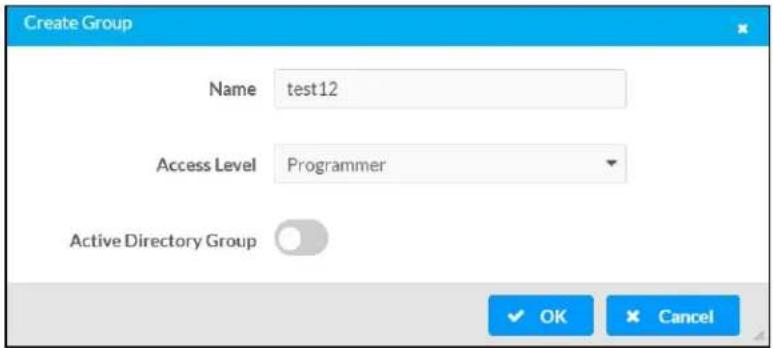
- Click the Create Group button.
- In the Create Group dialog, enter the following:
a. Enter the group name in the Name field.
b. Assign the group access level by selecting a predefined access level (Administrator, Connect, Operator, Programmer, User) from the Access Level drop-down list.
NOTE: Make sure that the Active Directory Group toggle is disabled.
- Click OK to save. Click Cancel to cancel the changes.
Add Active Directory Group
A group cannot be created or removed from the Active Directory server, but access can be granted to a existing group in Active Directory.

Once the group is added, all members of that group will have access to the DM-NAX-BTIO-1G.
- Click the Create Group button.
- In the Create Group dialog enter the following:
a. Enter the group name in the Name field, for example "Engineering Group". Note that group names are case sensitive; a space is a valid character that can be used in group names.
- Assign the group access level by selecting a predefined access level (Administrator, Connect, Operator, Programmer, User) from the Access Level drop-down list.
NOTE: Make sure that the Active Directory Group toggle is enabled.
- Click OK to save. Click Cancel to cancel the changes.
Delete a Group
Click the trashcan button (☐) in the Actions column to delete a group. Click Yes when prompted to delete the group or No to cancel the deletion.
When a group is deleted, users in the group are not removed from the device or Active Directory server. However, because a user's access level is inherited from a group(s), users within the deleted group will lose access rights associated with the group.
View Group Details
Click the information button (6) in the Actions column to view information for the selected group. The Group Details dialog lists the following information for the selected group.

• Name: Displays the name of the group.
- Access Level: Displays the access level of the group and its users.
• Active Directory Group: Displays whether the group is an Active Directory group.
Click OK to close the Group Details dialog and to return to the Groups tab.
802.1x Configuration
The DM-NAX-BTIO-1G has built-in support for the 802.1X standard (an IEEE network standard designed to enhance the security of wireless and Ethernet LANs. The standard relies on the exchange of messages between the device and the network's host, or authentication server), allowing communication with the authentication server and access to protected corporate networks.
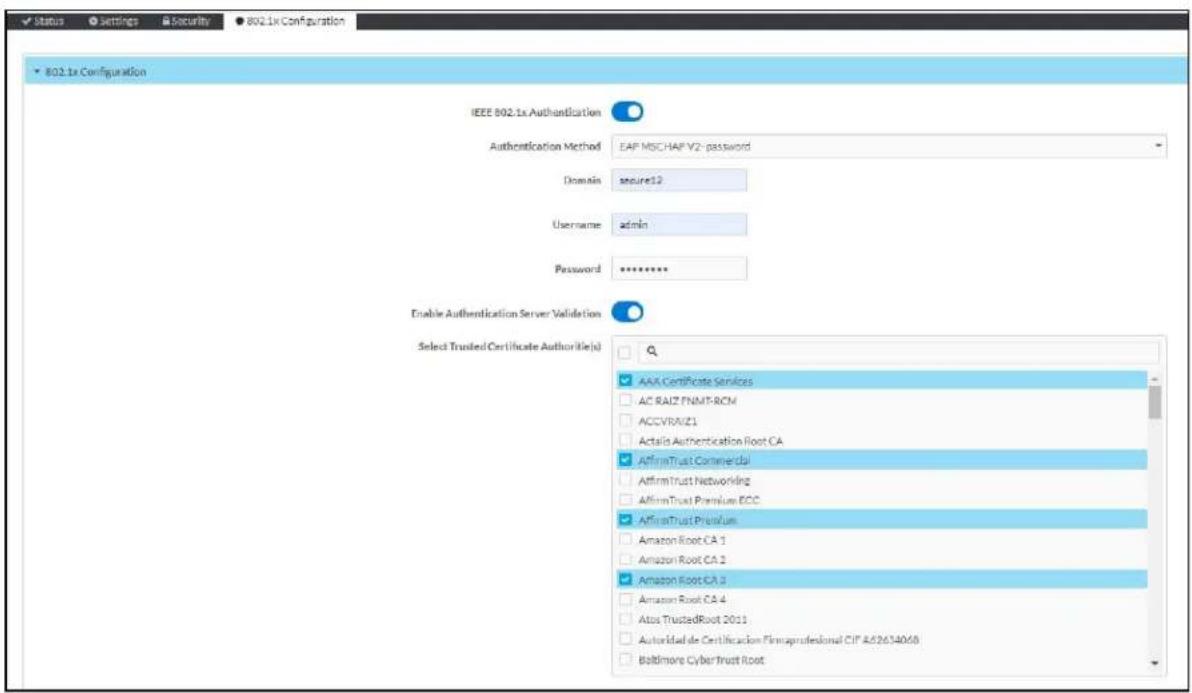
To Configure DM-NAX-BTIO-1G for 802.1X Authentication
-
Set the IEEE 802.1X Authentication toggle to enabled. This will enable all options on the 802.1X dialog.
-
Select the Authentication method: EAP-TLS Certificate or EAP-MSCHAP V2 Password according to the network administrator's requirement.
-
Do either one of the following:
- Select EAP-TLS Certificate, click Action/Manage Certificates to upload the required machine certificate. The machine certificate is an encrypted file that will be supplied by the network administrator, along with the certificate password.
- Select EAP-MSCHAP V2 Password, enter the username and password supplied by the network administrator into the Username and Password fields. This method does not require the use of a machine certificate, only the user name and password credentials.
- If you enabled the Enable Authentication Server Validation option, this will enable the Select Trusted Certificate Authoritie(s) list box which contains signed Trusted Certificate Authorities (CAs) preloaded into the DM-NAX-BTIO-1G.
Select the check box next to each CA whose certificate can be used for server validation, as specified by the network administrator.
If the network does not use any of the listed certificates, the network administrator must provide a certificate, which must be uploaded manually via the Manage Certificates functionality.
-
If required, type the domain name of the network in the Domain field.
-
When the 802.1X settings are configured as desired, click Save Changes to save the changes to the device and reboot it. Click Revert to cancel any changes.
Access the Web Interface With the Crestron Toolbox Application
To access the web interface by opening a web browser within the Crestron Toolbox™ application, do the following:
-
Open the Crestron Toolbox application.
-
From the Tools menu, select Device Discovery Tool. You can also access the Device Discovery Tool by clicking the Device Discovery Tool button ( ) in the Crestron Toolbox toolbar. The DM-NAX-BTIO-1G is discovered and listed in the device list on the left side of the screen. The associated host name, IP address, and firmware version are also displayed.
NOTE: If there is security software running on the computer, a security alert might be displayed when the Crestron Toolbox application attempts to connect to the network. Make sure to allow the connection, so that the Device Discovery Tool can be used.
-
In the Device Discovery Tool list, double-click your device.
-
Enter your credentials in the Authentication Required dialog that opens, and then click Log In.
-
Click the Web Configuration button in the Configuration page displayed on the left side of the Device Discovery Tool.
Resources
The following resources are provided for DM NAX®.
NOTE: You may need to provide your Crestron.com web account credentials when prompted to access some of the following resources.
Crestron Support and Training
- Crestron True Blue Support
• Crestron Resource Library
• Crestron Online Help (OLH)
• Crestron Training Institute (CTI) Portal
Programmer and Developer Resources
- help.crestron.com: Provides help files for Crestron programming tools such as SIMPL, SIMPL#, and Crestron Toolbox™ software
• developer.crestron.com: Provides developer documentation for Crestron APIs, SDKs, and other development tools
Product Certificates
To search for product certificates, refer to support.crestron.com/app/certificates.
- Original Instructions
- Regulatory Model: M1845004
- Contents
- Overview .1
- Specifications
- Installation .64
- Resources 641
- Overview
- Features
- Products
- DM-NAX-2XLRI-1G
- Audio-over-IP
- Line Level and Microphone Level Support
- Digital Signal Processing (DSP)
- Encoder and Decoder Functionality
- DM-NAX-8ZSA
- Physical Description
- Front Panel
- Rear Panel
- Applications
- NOTES:
- DM-NAX-16AIN
- Application
- DM-NAX-4ZSA-50
- Streaming and Casting Services
- Chimes
- Modular Design
- Gallium Nitride (GaN) Amplification
- DM-NAX-4ZSP
- DM-NAX-AMP-X300
- Lo-Z (4/8 Ω) and Hi-Z (70V or 100V) Output
- ENERGY STAR® Certified
- Fully Protected
- DM-NAX-AUD-IO
- DM-NAX-AUD-USB
- USB Audio
- DM-NAX-BTIO-1G
- Bluetooth® Wireless Connectivity
- Front Panel Controls and Display
- DM-NAX-2XLRI-1G Specifications
- Audio
- Connectors
- Controls and Indicators
- Power
- Environmental
- Construction
- Dimensions
- Weight
- Compliance
- DM-NAX-8ZSA Specifications
- Communications
- DM-NAX-4ZSA-50 Specifications
- DM-NAX-4ZSP Specifications
- Dimension Drawing
- DM-NAX-16AIN Specifications
- DM-NAX-AMP-X300 Specifications
- Dimension Drawings
- DM-NAX-AUD-IO Specifications
- DM-NAX-AUD-USB Specifications
- DM-NAX-BTIO-1G Specifications
- Installation
- DM-NAX-2XLRI-1G Installation
- In the Box
- Mounting the Device
- Mounting onto a Rack Rail
- Mounting to a Flat Surface
- Connect the Device
- Reset the Device
- Network Reset
- Factory Restore
- DM-NAX-8ZSA Installation
- Qty. Description
- Install the Device
- Place on a Table
- Rack Installation
- Rack Mounting Safety Precautions
- CAUTION:
- NOTE:
- Digital Inputs
- Analog Inputs
- Speaker Connections
- Conventional Wiring
- Bridged Wiring
- Balanced/Unbalanced Audio Output
- Apple® AirPlay® Setup
- Spotify® Connect Setup
- Observe the LED Indicators
- DM-NAX-4ZSA-50 Installation
- Additional Items
- Double Mount
- Spotify® Setup
- DM-NAX-4ZSP Installation
- Place on a Flat Surface
- Install in a Rack
- DM-NAX-16AIN Installation
- Balanced/Unbalanced Audio Input
- DM-NAX-AMP-X300 Installation
- Mount on a Flat Surface
- Single Amp
- Double Amp
- Speaker Mode Selection Switch
- Lo-Z Modes Selection Switch
- Output Wiring Options
- DM-NAX-AUD-IO Installation
- Mount the Device
- Mounting under a Table
- Mounting into a 1-Gang Electrical Box
- DM-NAX-AUD-USB Installation
- DM-NAX-BTIO-1G Installation
- Configuration
- Web Interface Configuration
- Access the Web Interface
- Action
- Save Changes
- Revert
- Reboot the DM-NAX-2XLRI-1G
- Restore to Factory Default Settings
- Update Firmware
- Download Logs
- Manage Certificates
- To Add Certificates
- To Delete Certificates
- Status
- Device
- Network
- Control System
- Settings
- Commercial Mode
- System Setup
- Date/Time
- Time Synchronization
- Time Configuration
- Auto Update
- Adapter 1
- Device Modes
- Commissioning
- Output Channels
- Zone Settings
- Zone
- Delay
- Output
- Signal
- Input Channels
- Configure Inputs
- Equalizer Settings
- DM NAX Streams
- Configure Transmitters
- Configure Receivers
- Mixing
- Residential Mode
- Click Save Changes.
- Cloud Settings
- Balance
- Stereo/Mono
- Advanced Signal Generator
- Inputs
- NAX Streams
- Routing
- Security
- Current User
- Users
- Create a New Local User
- Add an Active Directory User
- Delete User
- View User Details
- Update User Details
- Groups
- Create Local Group
- Add Active Directory Group
- Delete a Group
- View Group Details
- 802.1x Configuration
- To Configure DM-NAX-2XLRI-1G for 802.1X Authentication
- Access the Web Interface With the Crestron Toolbox Application
- Reboot the DM-NAX-8ZSA
- Manage Audio Profiles
- To Add a Speaker Profile
- To Delete a Speaker Profile
- Download Configuration
- Upload Configuration
- Zones
- Tone
- Minimum/Maximum Volume
- Bussing Volume Offset
- Configure Speaker Profile
- Speaker Configuration
- Casting
- Speaker/Faults
- Line Out
- Bussing
- Configure Bussing
- Streaming Services
- User Authentication
- Port Selection
- To Configure DM-NAX-8ZSA for 802.1X Authentication
- Reboot the DM-NAX-4ZSA-50
- Speaker Configuration (Zones 1 through 4 only)
- To Configure DM-NAX-4ZSA-50 for 802.1X Authentication
- Reboot the DM-NAX-4ZSP
- SOUNDMACHINE
- Login
- To Configure DM-NAX-4ZSP for 802.1X Authentication
- Reboot the DM-NAX-16AIN
- To Configure DM-NAX-16AIN for 802.1X Authentication
- Reboot the DM-NAX-AMP-X300
- Ducking
- To configure Port Selection:
- To Configure 802.1X Authentication
- Reboot the DM-NAX-AUD-IO
- Signal Generator
- To Configure DM-NAX-AUD-IO for 802.1X Authentication
- Reboot the DM-NAX-AUD-USB
- To Configure DM-NAX-AUD-USB for 802.1X Authentication
- CRESTRON®
- ▲ DEVICE FIRST BOOT
- Reboot the DM-NAX-BTIO-1G
- DM-NAX-BTIO-1G-C442683FC7EA
- Bluetooth Settings
- Main Bluetooth Settings
- Display
- Bluetooth
- To Configure DM-NAX-BTIO-1G for 802.1X Authentication
- Resources
- Crestron Support and Training
- Programmer and Developer Resources
- Product Certificates
Brand : Crestron
Model : DM-NAX-4ZSA-50
Category : Professional audio equipment