ATRC-36 - Cooker Atosa - Free user manual and instructions
Find the device manual for free ATRC-36 Atosa in PDF.


| Product Type | 36-inch Gas Range |
| Brand | Atosa |
| Model | ATRC-36 |
| Width | 36 inches (91.4 cm) |
| Depth | 28 inches (71.1 cm) |
| Height | 36 inches (91.4 cm) including backguard |
| Weight | Approximately 250 lbs (113 kg) |
| Power Source | Natural Gas or Propane (field convertible) |
| Burners | 6 open burners, 30,000 BTU each (total 180,000 BTU) |
| Oven | Convection oven, 5.5 cu ft capacity |
| Oven BTUs | 38,000 BTU |
| Grill/Girdle | Optional drop-in griddle or charbroiler available |
| Control Knobs | Heavy-duty metal knobs with cool-touch |
| Safety Features | Flame failure safety device on each burner, oven door safety interlock |
| Ignition | Electronic ignition with automatic reignition |
| Construction | Stainless steel front, sides, and backguard; porcelain-enamel oven interior |
| Legs | 6 adjustable stainless steel legs with feet |
| Cleaning | Removable oven door for easy cleaning; burner grates are dishwasher safe |
| Maintenance | Regular cleaning of burner ports and oven interior recommended |
| Repairability | Common replacement parts available; modular design for servicing |
| Certifications | ETL, NSF, and CSA listed |
Frequently Asked Questions - ATRC-36 Atosa
User questions about ATRC-36 Atosa
0 question about this device. Answer the ones you know or ask your own.
Ask a new question about this device
Download the instructions for your Cooker in PDF format for free! Find your manual ATRC-36 - Atosa and take your electronic device back in hand. On this page are published all the documents necessary for the use of your device. ATRC-36 by Atosa.
USER MANUAL ATRC-36 Atosa
Gas Radiant Countertop Char Broilers Operating Instructions
Before you begin, please read these instructions carefully to use this product correctly, to make the product perform ideally, and to avoid hazards.
Models : ATRC-24 / ATRC-36 / ATRC-48
Dear customers and users:
Thank you for purchasing our products. In order to be able to better use this product, please read these instructions carefully before any operation, and follow the guide, to avoid any unnecessary trouble during using.
Please keep this instruction manual in a safe place for convenient reference and operation.
This instruction manual is subject to any change without further notice, and the manufacturer reserves the right of final interpretation.
The appliance is designed for commercial purposes, not for household use.
A statement instructing the purchaser to post in a prominent location instructions to be followed in the event the user smells gas. This information shall be obtained by consulting the local gas supplier
FOR YOUR SAFETY
Do not store or use gasoline or other flammable vapors or liquids in the vicinity of this or any other appliance.
WARNING: Improper installation, adjustment, alteration, service or maintenance can cause property damage, injury or death. Read the installation, operating and maintenance instructions thoroughly before installing or servicing this equipment.
Gas Radiant Countertop Char Broilers Installation, Operation and Maintenance Guide
Contents
- Safety Protection 3
- Brief Introduction......3
- Manufacturer's Authority and Responsibility 3
- Parameter Specifications……4
- Transport and Storage 6
- Installation and Debugging......6
- Safety Notices and Precautions 8
- Operating Instructions......9
- Cleaning and Maintenance……12
- Troubleshooting 14
- Spare Parts....15
- Accessories List....18
1. Safety Protection
Please make sure that the operator is an authorized and licensed technician before you allow him/her to install and operate the products. Be sure to strictly follow this instruction guide during installation and using. The manufacturer is not responsible for any dangers or accidents caused by improper operation or maintenance.
Do not store flammable or explosive objects around the product. Keep all flammable and explosive objects at a safe distance away from the product for normal use.
Place the product in a reasonable position. Regarding related matters of gas, customer should execute the requirements of local gas supply sector; If you smell a gas leak, turn off the gas valves immediately and call the gas company;
The product should not be operated by those under 18 years of age, or those with physical or mental disorders, or disabilities that lack the necessary knowledge or experience unless with appropriate instructions and sufficient safety.
2. Brief Introduction
The product is a series of gas char broilers in our company production, which is novel designed, reasonable structured, convenient operated, durable used, and convenient maintained. It's equipped with a high efficiency stainless steel tubular burner and a pilot light, and convenient to ignite the main fire burner. This is hotel, supermarket, western restaurant, noshery and food industry's ideal barbecue product equipment.
3. Manufacturer's Authority and Responsibility
Banning of all or partial transformation to the products without the manufacturer's explicit authorization.
The Manufacturer refuses to undertake responsibility to third parties for the following reasons:
Not follow the instruction guide and take caution in using and testing; Not comply with the requirements of technical parameters using this product; Incorrectly or irrationally using the product by untrained personnel;
Not obey the local law using this product;
Be repaired or changed by unauthorized technicians;
Use the spare parts or accessories provided by non-manufacturer;
Accidents caused by force majeure;
Not strictly comply with related guide of instruction by any reason.
4. Parameter Specifications
4.1、Outline Dimensions (inch) ^*
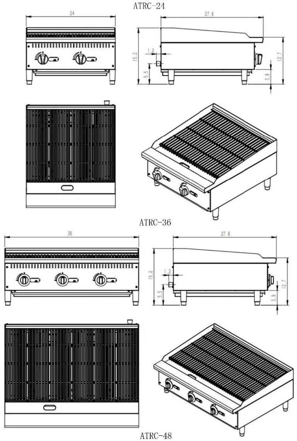
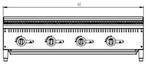
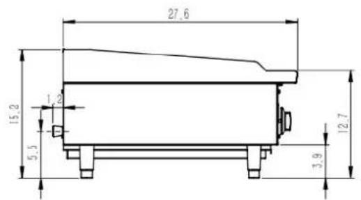
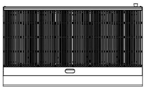
natural_image
Front view of a black and white industrial ventilation grille with vertical slats and a small button (no text or symbols)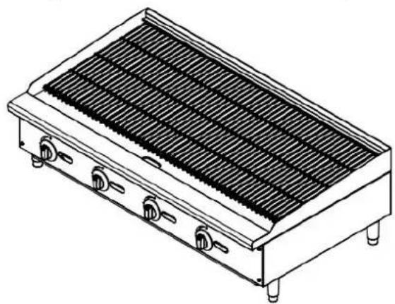
natural_image
Line drawing of a rectangular industrial grater with heat sinks and mounting feet (no text or symbols)4.2、Gas Supply and Burner Information
The minimum supplied gas pressure regulator is factory set at 4" Natural Gas W.C, and 10" L.P. Gas W.C. The external thread of product's intake-tube is 3/4 inches.
| Model | #of burners and control method | Gas Species | Intake-tube pressure (in. W. C.) | Per BTU B. T. U. /h | Total BTU B. T. U. /h | Nozzle No. |
| ATRC-24 | 2 pieces Independent control | Natural Gas | 4 | 35,000 | 70,000 | #36 |
| L. P. Gas | 10 | 35,000 | 70,000 | #50 | ||
| ATRC-36 | 3 pieces Independent control | Natural Gas | 4 | 35,000 | 105,000 | #36 |
| L. P. Gas | 10 | 35,000 | 105,000 | #50 | ||
| ATRC-48 | 4 pieces Independent control | Natural Gas | 4 | 35,000 | 140,000 | #36 |
| L. P. Gas | 10 | 35,000 | 140,000 | #50 |
5. Transport and Storage
In the process of transportation, handle carefully and keep upright to prevent damage to the product packing. Wrapped equipment should not be long-term open storage, and shall be placed in a well-ventilated and non-corrosive gases warehouse. When equipment needs temporary storage, rainproof measures should be taken.6. Installation and Debugging
Any erroneous installation, adjustment, refit, overhaul or maintenance may cause property damage or personal injury. All this work shall be completed by authorized and licensed technicians, otherwise the manufacturer has the right not to provide warranty service; Only be installed in accordance with the local code. If no similar standard, you should conform to the National Fuel Gas Code, ANSI Z223.1/NFPA 54, the National Gas Installation Code, CSA-B149.1, or the L.P. Gas Installation Code, CSA-B149.2 as applicable; The appliance individual shutoff valve must be disconnected from the gas supply piping system during any pressure testing of that system at test pressures in excess of 1/2psi (3.45kPa).6.1、Unpacking and Installation
Please dispose of all packaging materials and residues after unpacking; Check the equipment. If it is damaged, please keep wrappers and receipts, which must be signed by the carrier representative (Driver), and contact the carriers to pursue a claim within 15 days after receiving; Check all accessories complete. Refer to P17 table 5; Be sure to install supporting legs before using, and do not tear up any label or logo before the normal using; Please read these instructions carefully before installation and operation. Please contact your local agent if you have any questions; The charbroiled shall be installed on a level, solid, non-skid and incombustible surface, and placed in a well-lighted work area with waterproof, and away from children and customers; The installation position is a well-ventilated place in accordance with the local regulations; The charbroiled must be installed under the matched cooking fume exhauster according to the local regulations; Important: Installation and ventilation laws, and codes are very different, you should state and comply with all codes of the National Fire Protection Association Inc when it comes to requirements for installation of equipment; Screw 4 adjustable stainless steel legs in the tapping hole with four corners of the char broiler bottom, ensure sufficient space for ventilation; Adjustable stainless steel legs to make the equipment level, and get the same level with other series of the same stove; Please lift the equipment rather than drag if you need to move it; Open the grate, and take out the support under it, and reinstall grate after you make sure the thermal radiation plate is unmoved, and dispose the support; Supplied gas pressure regulator is factory set at 4" Natural Gas W.C, and 10" L.P. Gas W.C; The equipment can only be placed on the nonflammable counter top, and keep a distance of at least 6 inches(152mm) to equipment's both sides and back, and keep a distance of at least 4 inches(102mm) to the bottom; Do not put anything around the equipment, and on the counter top and bottom, in order to avoid influencing combustion and air circulation; Leave enough distance in front of the equipment to take apart the control panel. All major parts, in addition to the burner remove from the front intake-tube; It may be necessary to adjust the balance of air input by authorized and licensed technicians; Pipe threading compound must be resistant to the action of liquefied petroleum gases. Warning! Use soap water or testing instrument to test whether piping joint leaks before use, and forbidden to use an open flame to test! After installing, you should check gas supply pressure. Use a pressure gauge which is equipped with liquid (such as U-type pressure gauge, the minimum value is 0.1mbar) or a digital pressure gauge to test. Steps as following: \- Remove counter top plate, and needle type pressure joint screw arbor (Fig. 1), then slip rubber tube of pressure gauge over needle type pressure joint; \- Start the equipment in accordance with the instructions, measuring gas supply pressure (dynamic pressure) in the work state; \- Access to the equipment if measured data within the limits of table 1, otherwise,  you will need to adjust gas pressure regulating valve or contact gas supplier to bargain; ●Unplug pressure gauge after you accomplish pressure testing, then install needle type pressure joint screw arbor. Important: must screw joint screw arbor to prevent Fig.1 gas escape!6.2、Debugging
It's very important to debug the new stove. Through the comprehensive system test of equipment, we can ensure product's function and safety performance. Discovering any potential problems before use (such as equipment's placement, ventilation, operation, etc), can avoid costly losses.7. Safety Notices and Precautions
Warning! For your safety, do not place petrol and other flammables nearby. Please keep clean and free of flammables surroundings. (Read ANSI Z83.14B, 1991 for reference) Warning! Any erroneous installation, adjustment and refit may cause property damage or personal injury and maintenance failure. Read the instructions carefully before installation and using. Warning! Operation instruction must be placed in a conspicuous location. When customers smell gas in the process of using, should take safety precautions immediately. Immediately turn off the main gas valve, extinguish all heat and flames, and call 911. Safety information can be obtained from your local gas suppliers. When using this equipment, safety precautions should always be followed, including the following: The char broilers burners, grates and outside surfaces may become hot after using, so you must be careful to touch; During operation, do not directly touch burners and grates; Turn off the equipment as not in using, cleaning, servicing or adjusting any parts or attachments. If the equipment has any problems of equipment damage, gas piping leaks, igniter or valves damage, or lose product accessories, do not operate by yourself and call customer service immediately; The use of attachments not recommended or sold by the manufacturer may cause fire, personal injury, even death; Do not use out of doors; The equipment is used for barbecue, not available for any other use; The equipment does not contain any user-serviceable parts. Dealers or technicians will repair it. Do not take apart any spare parts without authorization; Never change any other parts without authorization to this equipment, otherwise, may cause hazards, and the manufacturer has the right not to provide warranty service; Steel cutting producers used to manufacture with sharp edges. The manufacturer has dealt with these sharp edges during production, however, we insist the operator take care when in contact with this piece of equipment; Always keep hands, hair and clothing away from heating source. Waiting until the unit cools down before you clean. Because the unit is too hot to handle after using.8. Operating Instructions
Before operating, make sure place the unit horizontally by adjusting bottom adjustable legs, and place the catch tray properly. The pilot light has been set at the factory. Each burner has a pilot light.8.1、Lighting the pilot light
Turn the control valve at the position of “0” (Fig. 2), make sure all knobs are in the close state. Light and hold an ignition source at the pilots. The pilot light may not be lighted immediately, for existing gas in the pipe. Wait a minute, the pilot light will be lighted after the gas extinguished. Tips: You can use a screwdriver to adjust the height of the flame (Fig.3).8.2、Lighting the main burner
Revolve the main fire control valve knob counterclockwise after lighting the pilot light, then the main fire burner is lighted by the pilot light. The power of burner increases as revolving angel increases. When knob reaches to " ▲", burner is in the maximum power (Fig. 4). natural_image
3D rendered mechanical component with curved surfaces and a central V-shaped groove (no text or symbols)natural_image
Close-up of a metallic tool securing a metal rod into a pipe (no text or symbols visible)natural_image
3D mechanical component diagram showing a circular housing with internal blades and a shaft, no text or symbols presentFig. 2 Fig. 3 Fig. 4
Make sure air circulation at the bottom of equipment; Do not use fan or air-conditioning blowing at the flame, in order to avoid extinguishing flame, and cause safety accidents; Install the matched cooking fume exhauster according to the local regulations over the char broiler; Make sure to keep natural air circulation in the kitchen.8.3、Turn off the valve
Revolve the control valve knob clockwise to "0" (Fig.1), so that extinguish flame of the main burner, but the pilot light still works. After turning off the equipment, the main fire should be stop more than 5 minutes before next using.8.4、Stove Operation
Before using the stove for the first time, please use a mild detergent to wipe it clean. Do not use corrosive or abrasives detergent. Turn the burners on about 15-20 minutes before broiling for preheating, according to the cooking requirement to adjust the flame size. Notice: When first preheating, the furnace will smoke rise. This is because of protective lipids on the grates and other parts are heated, it is normal, and it will be eliminated after the power up to the maximum for burning an hour. One side of grate with grease trough (Fig. 5), and on the other side of grate is flat (Fig. 6), users can choose a side according to demand, users also can adjust grate's gradient according to demand (Fig. 7). The side of grate with grease trough up if roasting food with more oil, and oil will drop into grease trough, then flow to catch tray. natural_image
Two side-by-side images showing vertical metal grating structures with no visible text or symbols.natural_image
Technical line drawing of two mechanical components with mounting holes and grooves (no text or symbols)8.5、Exchange main fire nozzle to switch gas source
Remove control panel, grate and heat storage plate, remove the pilot light head, and bottom tightening screw of the end of burner (arc), then remove main fire nozzle with proper open spanner, exchange nozzle of another gas source, then screw it (Fig. 8). Reinstall burner, the pilot light head, cooking grates and control panel in proper place. Caution: Each main fire nozzle of the burner has been installed before delivery, normal use without adjustment but only switching gas. Adjust only by authorized and licensed technicians. When you converse the gas source, exchange the corresponding pressure maintaining valve which installed on air intake. See 2 in P18.8.6、Adjust air input
Remove control panel, unscrew damper solid screw(Fig.9), revolve damper left to right (Fig.10), meanwhile, observe flame and adjust an appropriate opening degree. Then screw damper solid screw, make sure the equipment will not get loose in the process of moving and translation. Reinstall control panel. Caution: Each burner damper has been adjusted before delivery (once air input), normal use without adjustment but only switching gas. Adjust only by authorized and licensed technicians. natural_image
Three-panel photo showing a wrench tool, a metallic screwdriver, and a hand holding a brass-colored connector (no text or symbols visible)9. Cleaning and Maintenance
Do not use any abrasive or flammable detergent to wipe; Do not hose down, immerse or pressure wash any part of the char broiler, excluding the catch tray; Do not use abrasive cleaning matters to wash, even not use corrosive detergent! Warning: Before cleaning, all control valves must be turned off. Strictly follow the lighting instructions to work again after cleaning! Warning: Wait for the equipment cool down before your cleaning! Cut off the gas source as not in using; If the equipment is not used for a long time, clean the surface by wiping it with a soft cloth and place it in a well-ventilated area; Comprehensively check the equipment at least once every year by authorized and licensed technicians; The product is made of 90% metals, and can not be disposed anywhere. Deal with it in accordance with the local codes. Instructions to clean appliance regularly with recommended cleaning agents, if necessary. Recommended cleaning methods| Item | Method | Time |
| Body | Wipe it with a soft cloth and mild detergent | daily |
| Control panel | Turn off the valves when not in use; Wipe panel and control valve knob with mild detergent. | daily |
| Grates & Radiants | Caution: Wear insulated gloves who handling grates or radiants, in order to prevent possible burns!1. Take out grates and radiants;2. Clean up grease and other impurity on grates with a wire brush;3. Clean grid slot with a scraper;4. Grates coated with food grade lubricants. Reinstall radiant and grate in proper order, open char broiler to evaporate for 45 minutes, then close it.Warning: Do not cover grates in the process of evaporation! | daily/as need |
| Char GrateBack SupportBrace | Remove grate until the equipment cools down. Take off char grate ba support brace, clean grease and other crumbs. Then daub lubricantsReinstall after cleaning. | daily/as need |
| Catch tray | Pull out catch tray from front box until the equipment cools down.Clean grease and other crumbs.Reinstall after cleaning and daubing lubricants.Warning: if the catch tray is permitted to fill too high, should be cleaned! | Per use |
10. Troubleshooting
| Problems | Possible causes | Problem solving |
| Not lighting | 1. Insufficient gas pressure in pipe | 1. Contact the local gas supply dept. |
| 2. Nozzle occlusion | 2. Dredge nozzle | |
| Ignite the pilot light but not the main fire | 1. Insufficient gas pressure in pipe | 1. Contact the local gas supply dept. |
| 2. The main fire nozzle occlusion | 2. Dredge nozzle | |
| 3. Gas control valves have problems | 3. Change gas control valves | |
| 4. The pilot light and the main fire's distance is too far | 4. Adjust the distance of them | |
| 5. Flame is too low | 5. Adjust the height of the pilot light | |
| Close gas and heard a sound of fire | 1. Insufficient gas pressure in pipe | 1. Contact the local gas supply dept. |
| 2. Not match nozzle aperture with gas resources | 2. Adjust nozzle diameter | |
| 3. Flow of connection pipe is not enough | 3. Increase pipe's allowable flow | |
| 4. Damper opening degree is too large | 4. Adjust damper | |
| Yellow flame and black smoke | 1. Use bottom gas | 1. Change gas |
| 2. Not match nozzle aperture with gas resources | 2. Adjust nozzle diameter | |
| 3. Not enough air to ignite | 3. Increase damper opening degree | |
| 4. In the peak of using gas, sources of gas float heavy | 4. Turn down valves flow. Turn it up after the peak |
11. Spare Parts
The use of parts provided by other companies, our company has the right not to provide warranty service; Order replacement parts from authorized representatives and after-sale service agency. Provide the model number, serial number and description when you order components.  Fig. 11| No. | Matters Code | Component name | Qty | Dimensions (mm)/Model | Remark |
| 1 | 301110001 | Adjustable steel leg | 4 | 41.5*100 | ATRC-24\36\48 |
| 2 | 21105001001 | Catch tray | 1 | 507*620*26.5 | ATRC-24 |
| 21105002001 | 807*620*26.5 | ATRC-36 | |||
| 21105003001 | 1107*620*26.5 | ATRC-48 | |||
| 3 | 301080002 | Galvanized flange face nut | 6 | M6 | ATRC-24 |
| 9 | ATRC-36 | ||||
| 11 | ATRC-48 | ||||
| 4 | 301082001 | Galvanized flat grommet | 4 | 6* 10 | ATRC-24 |
| 6 | ATRC-36 | ||||
| 7 | ATRC-48 | ||||
| 5 | 301081006 | Galvanized American outside six corner with pad tapping | 24 | ST4.8*12.5 | ATRC-24\36\48 |
| 6 | 21105001002 | Control panel | 1 | 605*185 | ATRC-24 |
| 21105002002 | 905*185 | ATRC-36 | |||
| 21105002002 | 1205*185 | ATRC-48 | |||
| 7 | 301140001 | Kirsite knob | 2 | ATRC-24 | |
| 3 | ATRC-36 | ||||
| 4 | ATRC-48 | ||||
| 8 | 301060001 | Needle type pressure joint | 1 | 1/8"-27NPT | ATRC-24\36\48 |
| 9 | 301060002 | Needle type pressure joint screw arbor | 1 | M5*23 | ATRC-24\36\48 |
| 10 | 301030002 | A18 stopcock | 2 | A18-318 | ATRC-24 |
| 3 | ATRC-36 | ||||
| 4 | ATRC-48 | ||||
| 11 | 301040006 (NG)301040007 (LP) | A18 nozzle (NG)A18 nozzle (LP) | 2 | NG36LP50 | ATRC-24 |
| 3 | ATRC-36 | ||||
| 4 | ATRC-48 | ||||
| 12 | 301030001 | Pilot light valve-single unit | 2 | AP7-1 | ATRC-24 |
| 3 | ATRC-36 | ||||
| 4 | ATRC-48 | ||||
| 13 | 301070013 | Air input pipe | 2 | 4.7*0.6 L=400 | ATRC-24 |
| 3 | ATRC-36 | ||||
| 4 | ATRC-48 | ||||
| 14 | 301170015 | Pilot light head stator | 2 | ATRC-24 | |
| 3 | ATRC-36 | ||||
| 4 | ATRC-48 | ||||
| 15 | 301060003 | Pilot light head | 2 | A73007/TiP 4.7 | ATRC-24 |
| 3 | ATRC-36 | ||||
| 4 | ATRC-48 | ||||
| 16 | 21205001001 | countertop | 1 | 610*700*218 | ATRC-24 |
| 21205002001 | 910*700*218 | ATRC-36 | |||
| 21205003001 | 1210*700*218 | ATRC-48 | |||
| 17 | 301020003 | grates | 4 | 150*525*22 | ATRC-24 |
| 6 | ATRC-36 | ||||
| 8 | ATRC-48 | ||||
| 18 | 21205001003 | Char grate back support brace | 1 | L=600 | ATRC-24 |
| 21205002003 | L=900 | ATRC-36 | |||
| 21205003003 | L=1200 | ATRC-48 | |||
| 19 | 301170002 | Radiants(short) | 2 | 92*103 | ATRC-24 |
| 3 | ATRC-36 | ||||
| 4 | ATRC-48 | ||||
| 20 | 301170001 | Radiants(long) | 4 | L=451 | ATRC-24 |
| 6 | ATRC-36 | ||||
| 8 | ATRC-48 | ||||
| 21 | 301010007 | U-type burner | 2 | ATRC-24 | |
| 3 | ATRC-36 | ||||
| 4 | ATRC-48 | ||||
| 22 | 301030014 | pressure maintaining valve | 1 | 4”-10” | ATRC-24\36\48 |
| 23 | 301070001 | 24” countertop char broiler intake-tube | 1 | Φ26-503*648 | ATRC-24 |
| 301070002 | 36” countertop char broiler intake-tube | Φ26-803*648 | ATRC-36 | ||
| 301070003 | 48” countertop char broiler intake-tube | Φ26-1113*648 | ATRC-48 | ||
| 24 | 21205001002 | surround | 1 | 600*640*203 | ATRC-24 |
| 21205002002 | 900*640*203 | ATRC-36 | |||
| 21205003002 | 1200*640*203 | ATRC-48 |
12. Accessories List
| Name Qty\Model | ATRC-24 | ATRC-36 | ATRC-48 |
| Adjustable steel legs | 4 pieces | 4 pieces | 4 pieces |
| Catch tray | 1 piece | 1 piece | 1 piece |
| pressure maintaining valve | 1 piece | 1 piece | 1 piece |
| A18 Orifice | 2 pieces | 3 pieces | 4 pieces |
| instructions | 1 piece | 1 piece | 1 piece |
Notice:
1、Pressure maintaining valve connects with air intake, must be installed by authorized and licensed technicians, to assure interface tightness. 2、Screw the hex nut (Fig.12) before connect air intake, ensure gas mark (Fig.13) on the plastic core whether match with connected gas source, if not, then pull out the plastic core and change another head, insert it again. The same as exchanging gas source. 3、When exchange gas source, use the A18 orifice (Fig. 14) in the accessories. Follow rules of 8.5.  Fig. 12 Fig. 13 Fig. 14  Conforms to ANSI STD Z83.11b-2009(2011) Certified to CSA STD 1.8b-2009(2011) Conforms to NSF/ANSI STD.4 Our products have the advantages of good durability and low maintenance charge. But to update some components and necessary maintenance, can prolong life length of the products. Contact the dealer for assistance. In order to avoid confusion, please follow the format in figure 11 and table 4.- Gas Radiant Countertop Char Broilers Operating Instructions
- FOR YOUR SAFETY
- Contents
- Safety Protection
- Brief Introduction
- Manufacturer's Authority and Responsibility
- Parameter Specifications
- 4.1、Outline Dimensions (inch) *
- 4.2、Gas Supply and Burner Information
- Transport and Storage
- Installation and Debugging
- 6.1、Unpacking and Installation
- 6.2、Debugging
- Safety Notices and Precautions
- Operating Instructions
- 8.1、Lighting the pilot light
- 8.2、Lighting the main burner
- Fig. 2 Fig. 3 Fig. 4
- 8.3、Turn off the valve
- 8.4、Stove Operation
- 8.5、Exchange main fire nozzle to switch gas source
- 8.6、Adjust air input
- Cleaning and Maintenance
- Troubleshooting
- Spare Parts
- Accessories List
- Notice:
Brand : Atosa
Model : ATRC-36
Category : Cooker