OTTICA - Security Camera Ikan - Free user manual and instructions
Find the device manual for free OTTICA Ikan in PDF.


| Product Type | Security Camera |
| Brand | Ikan |
| Model | OTTICA |
| Video Resolution | 1080p Full HD |
| Field of View | 120° |
| Night Vision | Up to 30 meters with IR LEDs |
| Audio | Two-way audio with built-in microphone and speaker |
| Connectivity | Wi-Fi 802.11 b/g/n, RJ45 Ethernet |
| Power Supply | DC 12V, 1A (adapter included) |
| Dimensions (W x H x D) | 70 x 70 x 120 mm |
| Weight | 250 g |
| Weather Rating | IP65 (indoor/outdoor use) |
| Storage | MicroSD card up to 128 GB, cloud storage optional |
| Motion Detection | Yes, with adjustable sensitivity and alerts |
| Mobile App | Compatible with iOS and Android |
| Mounting | Wall or ceiling mount included |
| Operating Temperature | -10°C to 50°C |
| Certifications | CE, FCC, RoHS |
| Warranty | 2 years |
| Manual Language | English |
Frequently Asked Questions - OTTICA Ikan
User questions about OTTICA Ikan
0 question about this device. Answer the ones you know or ask your own.
Ask a new question about this device
Download the instructions for your Security Camera in PDF format for free! Find your manual OTTICA - Ikan and take your electronic device back in hand. On this page are published all the documents necessary for the use of your device. OTTICA by Ikan.
USER MANUAL OTTICA Ikan
OTTICA 20x Zoom NDI 1080/60P PTZ Video Camera
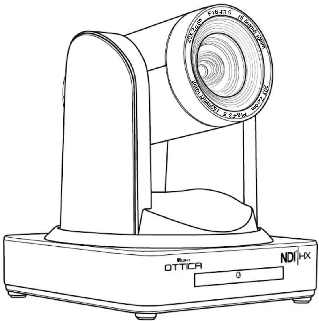
Table of Contents
- Getting....Started.... 3
1.1 Camera Interface
1.2 Power-On Initial Configuration 4
1.3 Video Output
1.4 Bracket Mount 5
- Product Overview
2.1 Product Introduction
2.1.1 Dimension 7
2.1.2 Accessory 7
2.2 Main Features 8
2.2.1 Camera Performance ....8
2.2.2 Network Performance 8
2.3 Technical Specifications 9
2.4 Interface____Instructions____ 11
2.4.1 External Interface 11
2.4.2 Bottom Dial Switch 12
2.4.3 RS-232 Interface 12
- Application Instructions 14
3.1 Remote Control 14
3.1.1 Keys Introduction 14
3.1.2 Applications 15
3.2 ...Menu Settings 17
3.2.1 Main Menu
3.2.2 System Settings 17
3.2.3 Camera Settings 18
3.2.4 P/T/Z 20
3.2.5 Video Format
3.2.6 Version 21
- Network Connection 22
4.1 Connecting....Mode.... 22
4.2 IE Log In
4.2.1 Web Client
4.2.2 Preview 24
4.2.3 Configuration 24
4.2.4 Audio Configuration
4.2.5 Video Configuration
4.2.6 Network Configuration 28
4.2.7 System Configuration 29
5.2 Pelco-D Protocol Command List 41
5.3 Pelco-P Protocol Command List 42
- Camera Maintenance and Troubleshooting 43
6.1 Camera....Maintenance....
6.2 Troubleshooting 43
43
1. Getting Started
1.1 Camera Interface
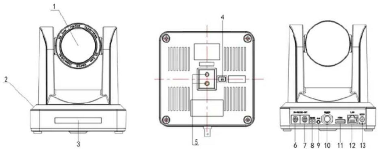
Figure 1.1 Interface of ST (standard) Series
- Camera Lens
- Camera Base
- Remote Controller Receiver Light
- Bottom Dial Switch
- Tripod Screw Hole
- RS232 Control Interface (input)
-
RS232 Control Interface (output)
-
RS485 Input (left +, right-)
- Audio Input Interface
- 3G-SDI interface
- HDMI Interface
- NDI | HX Interface
- DC12V Input Power Supply Socket
1.2 Power-On Initial Configuration
-
Power-On: Connect the DC12V power supply adapter into the power supply socket.
-
Initial Configuration: Upon powering on, the remote control receiver light will turn on and start blinking red. The camera head will move and adjust into the HOME position (intermediate position of both horizontal and vertical). When the remote control receiver light stops blinking red, it will stay on and turn green; this means the self-checking is finished.
- Note: After the Power-On self-test is completed If you press “set preset” then “0”, the camera head automatically moves to the preset HOME position any time you press “0”.
1.3 Video Output
The OTTICA has a variety of video outputs including LAN, HDMI and 3G-SDI.
- Video Output from LAN
A. Network Cable Connection Port: No.12 in Figure1.1;
B. Webpage Login:
- The OTTICA is set to auto DHCP so you'll need to connect the camera to devices that can automatically assign an IP address, such as routers and switches.
- Next, you'll have to use an IP scanning software to find the camera's IP address (visit the OTTICA product page at www.ikancorp.com to find a link to our recommended software for IP scanning).
- Copy and paste the camera's IP address and paste it into your web browser's address bar and press "Enter" to proceed into the login page.
- Enter the user name "admin" and password "admin" (factory default) and press "Enter" to proceed into the preview page.
- If you do not have the latest version of Flash installed, click on the button that says "Get ADOBE Flash Player.
- After you've installed the latest version of flash, the camera feed should be visible and you can now perform PTZ control, video recording, playback, configuration, and other operation.
-
NOTE: See chapter 4.1 for more details.
-
HDMI Video Output
A. HDMI Video Cable Connection: Refer to No.11 in Figure1.1.
B. Connect the camera and monitor via HDMI video cable.
- 3G-SDI Video Output
A. 3G-SDI video cable connection: Refer to No.10 in Figure1.1
B. Connect the camera and the monitor via 3G-SDI video cable
1.4 Bracket Mount
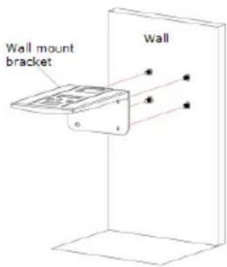
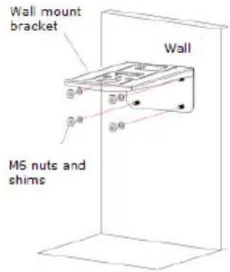
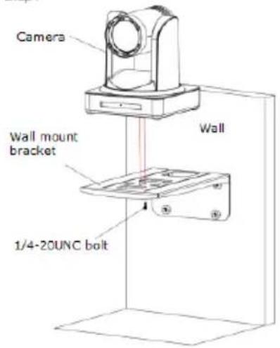
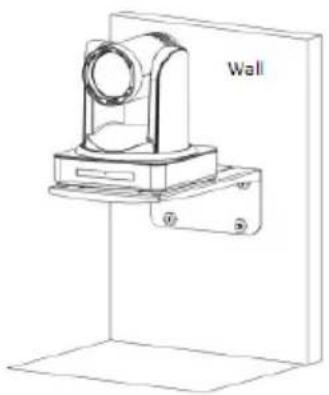
Note: The bracket can only be mounted on a wall or ceiling on either template or concrete wall, but cannot be installed on plasterboard.
Wall Mount Steps
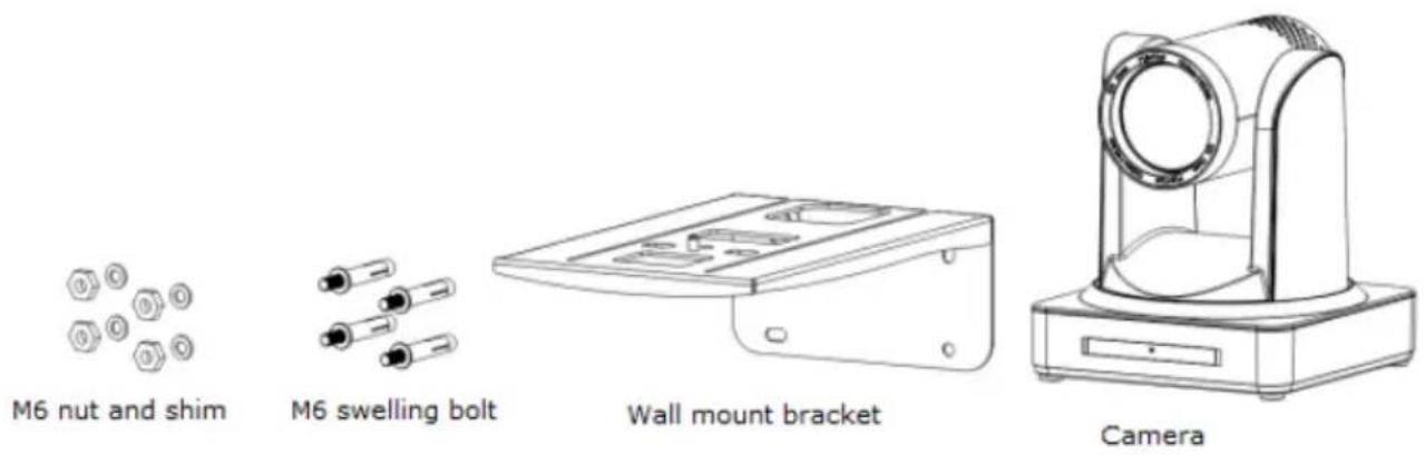
Step 1
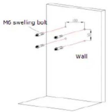
Step2
Step3
Step4
Finish
natural_image
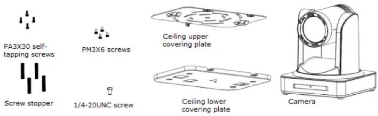
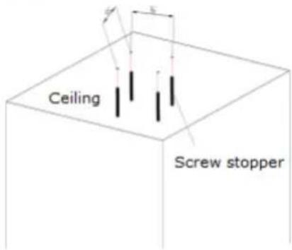
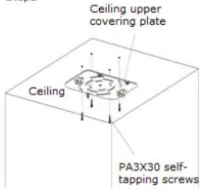
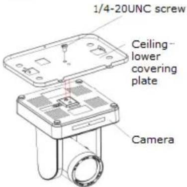
Technical line drawing of a mechanical device mounted on a wall, no text or symbols presentUpside-down Mount Steps (Ceiling Mount sold separately)
Step1
Step2
Step3
Step4
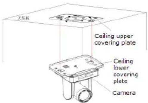
Step5
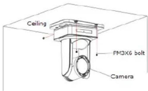
2. Product Overview
2.1 Product Introduction
2.1.1 Dimensions
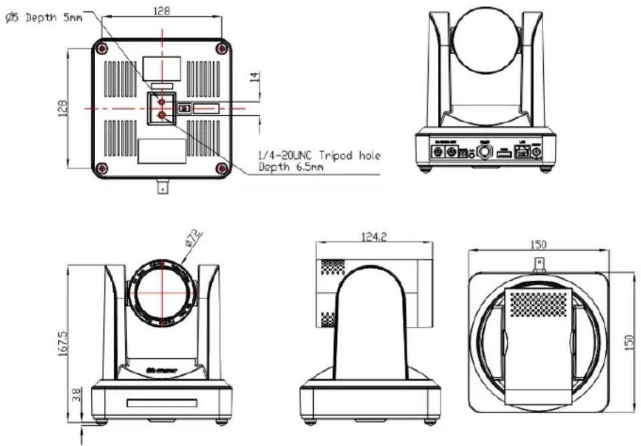
Figure 2.2 Camera Dimensions
2.1.2 Accessories
When unboxing, check that all the supplied accessories are included:
1 x Power Adapter
1 x RS232 Cable
1 x IR Remote Controller
1 x Wall Mounting Bracket
1 x RS485 Connector
1 x Cascade Cable
2.2 Main Features
2.2.1 Camera Performance
The OTTICA's features include advanced ISP processing algorithms to provide vivid images with a strong sense of depth, high resolution and fantastic color rendition. It supports H.265/H.264 encoding which makes motion video fluent and clear even with less than ideal bandwidth conditions.
- Superb High-definition Image: The OTTICA employs 1/2.8 inch high-quality CMOS sensor and supports resolutions up to 1920x1080 with frame rates up to 60 fps.
- Various Optical Zoom Lens: 5.5-110mm varifocal lens offers 20x optical zoom and viewing angle range from 3.3° to 54.7°
- Auto Focus Technology: OTTICA's auto focus algorithm makes the lens fast, accurate, and stable.
- Low Noise and High SNR: The Low Noise CMOS effectively ensures high SNR of the camera video. Advanced 2D/3D noise reduction technology is also used to further reduce the noise, while ensuring image sharpness.
- Quiet PTZ: By adopting a high accuracy step-driving motor mechanism, the OTTICA performs smoothly and quietly even when moving quickly to any position.
- Multi-Format Video Outputs: The OTTICA support HDMI, 3G-SDI, wired LAN and wireless LAN interfaces. The 3G-SDI will work up 100m distance with transmission at 1080p60 format.
- Low-power Sleep Function: The OTTICA supports a low-power sleep/wake up function. The consumption is lower than 500mW while in sleep mode.
- Support Multiple Control Protocol: The OTTICA supports VISCA, PELCO-D, PELCO-P protocols which can also be automatically recognized.
- RS-232 Cascade Function: The OTTICA supports RS-232 cascade function which is convenient for installing.
- 255 Presets Positions: Up to 255 presets (10 presets by IR remote).
2.2.2 Network Performance
- Audio Input Interface: 16000, 32000, 44100, 48000 sampling frequency and AAC, MP3, PCM audio coding are supported.
- Multiple Audio/Video Compression: The OTTICA supports H.264/H.265 video compression of resolutions up to 1920x1080p with frame rates up to 60 fps and 2 channel 1920x1080p with 30 fps. AAC, MP3, and PCM audio compression is supported.
- Multiple Network Protocol: Support NDIIHX; ONVIF, RTSP, RTMP protocols and RTMP push mode, easy to link streaming media server (Wowza, FMS).
2.3 Technical Specifications
| Camera Parameters | |
| Sensor 1/2.8 inch high quality HD | CMOS sensor |
| Effective Pixels 16: 9 2.07 megapixel | |
| Video Format | HDMI/SDI Video Format1080P60/50/30/25/59.94/29.97;1080I60/50/59.94;720P60/50/30/25/59.94/29.97 |
| Optical Zoom | 20XFocal range: 5.5-110mm |
| View Angle | 3.3° (tele)54.7° (wide) |
| AV F1.6 – F3.5 | |
| Digital Zoom 10X | |
| Minimum Illumination 0.5Lux (F1.8, AGC ON) | |
| DNR 2D & 3D DNR | |
| White Balance Auto / Manual/ One Push/ 3000K/ 4000K/5000K/6500K | |
| Focus Auto/Manual | |
| Aperture Auto/Manual | |
| Electronic Shutter Auto/Manual | |
| BLC ON/OFF | |
| WDR OFF/ Dynamic level adjustment | |
| Video adjustment | Brightness, Color, Saturation, Contrast, Sharpness, B/W mode, Gamma curve |
| SNR >55dB | |
| Input / Output Interface | |
| Video Interfaces | LAN (NDI | HX 4.0), HDMI, 3G-SDI, Audio-in, RS232 (In&Out), RS485 |
| Image Code Stream Double streams | outputs simultaneously |
| Video Compression format H.264, H.265 | |
| Control Signal Interface RS-232 | Ring through RS232 output, RS-485 |
| Control Protocol | VISCA/Pelco-D/Pelco-P; Baud Rate: 115200/9600/4800/2400bps |
| Audio input Interface Double track | 3.5mm linear input; |
| Audio Compression Format AAC/MP3/PMC Audio compression | |
| HD IP Interface | 100M IP Port(100BASE-TX); 5G WiFi (optional), support NDI, IP Visca control protocol |
| Network Protocol NDI,RTSP/RTMP,ONVIF | |
| Power Interface HEC3800 Outlet | (DC12V) |
| PTZ Parameters | |
| Pan Rotation ±170° | |
| Tilt Rotation -30°~+90° | |
| Pan Control Speed 0.1 -180°/sec | |
| Tilt Control Speed 0.1-80°/sec | |
| Preset Speed Pan: 60°/sec, Tilt: 30°/sec | |
| Preset Number 255 presets (10 presets by remote controller) | |
| Other Parameters | |
| Supply Adapter AC110V-AC220V | to DC12V/2A |
| Input Voltage | DC12V±10% |
| Input Current 1A(Max) | |
| Consumption | 12W (Max) |
| Store Temperature 14°F to +140°F | |
| Store Humidity 20% - 95% | |
| Working Temperature 14°F to +122°F | |
| Working Humidity 20%--80% | |
| Dimension 150mmX150mmX167.5mm | |
| Weight 3.08 LBS | |
| Working Environment Indoor | |
| Remote Operation (IP) Remote Upgrade, Reboot and Reset | |
2.4 Interface Instruction
2.4.1 External Interface
- External Interface: RS232 Input /Output, RS485 Input, Audio Input, 3G-SDI Output, HDMI Output, LAN, DC12V Power Interface.
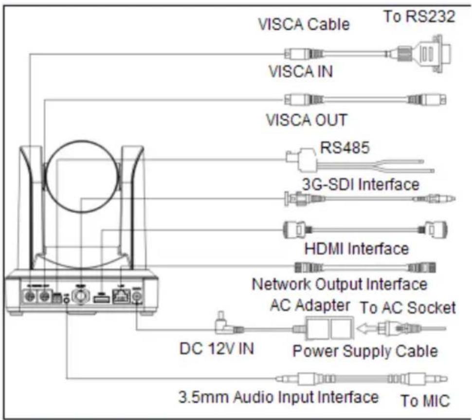
Figure 2.3 External Interface Diagram
2.4.2 Bottom Dial Switch
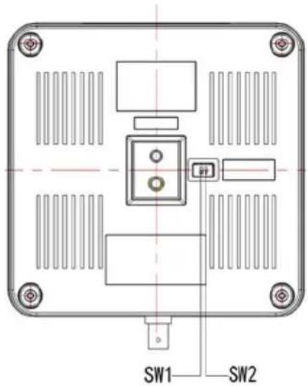
Figure 2.6 Bottom Dial Switch Diagram
Two DIP switches are set to ON or OFF to select different modes of operation.
| Table 2.2 Dial Switch Setting | |||
| No. SW1 | SW2 Explanation | ||
| 1 OFF | ON Working Mode | ||
| 2 ON | OFF Updating Mode | ||
Note: Working mode can be applicable for web upgrade.
2.4.3 RS-232 Interface
- RS-232C Interface Specifications
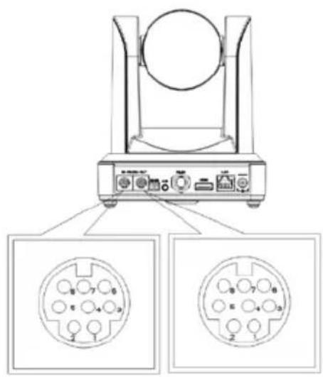
natural_image
Diagram of a mechanical device with two circular connector pins, no text or symbols present| Computer / Keyboard & Camera Connection Method | |
| Camera Windows DB-9 | |
| 1. DTR 1. DCD | |
| 2. DSR 2. RXD | |
| 3. TXD 3. TXD | |
| 4. GND 4. DTR | |
| 5. RXD 5. GND | |
| 6. GND 6. DSR | |
| 7. IR OUT | 7. RTS |
| 8. NC | 8. CTS |
| 9. RI | |
RS232 IN port on camera

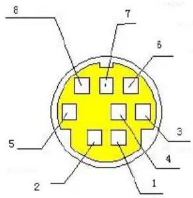
2. RS-232 Mini-DIN 8-pin Port Definition
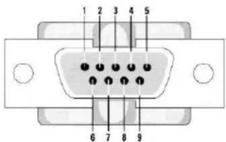
3. RS232 (DB9) Port Definition
| No. | Port Definition | |
| 1 | DTR Data Terminal Ready | |
| 2 | DSR Data Set Ready | |
| 3 | TXD Transmit Data | |
| 4 | GND System Ground | |
| 5 | RXD Receive Data | |
| 6 | GND System Ground | |
| 7 | IR OUT IR Commander Signal | |
| 8 | NC No Connection |
| No. Port Definition | |
| 1 DCD Data Carrier | Detect |
| 2 RXD Receive Data | |
| 3 TXD Transmit Data | |
| 4 DTR Data Terminal Ready | |
| 5 GND System Ground | |
| 6 DSR Data Set Ready | |
| 7 RTS Request to Send | |
| 8 CTS Clear to Send | |
| 9 RI Ring Indicator |
4. VISCA networking as shown below:
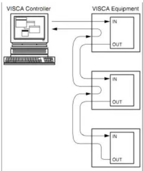
flowchart
graph TD
    A["VISCA Controller"] --> B["VISCA Equipment"]
    B --> C["IN OUT"]
    B --> D["IN OUT"]
    B --> E["IN OUT"]
    C --> F["Out"]
    D --> G["Out"]
    E --> H["Out"]
| Camera Cascade Connection Method | |
| Camera 1 Camera 2 | |
| 1. DTR 1. DTR | |
| 2. DSR 2. DSR | |
| 3. TXD | 3. TXD |
| 4. GND | 4. GND |
| 5. RXD 5. RXD | |
| 6. GND | 6. GND |
| 7. IR OUT | 7. OPEN |
| 8. NC | 8. OPEN |
Note: OTTICA has RS232 input and output interface, so you can cascade as shown above.
3. Application Instructions
3.1 Remote Control
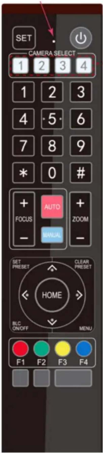
3.1.1 Keys Instruction
- Standby Key
After a 3-second long press, the camera will step into standby mode. After pressing the standby key for 3 seconds again, the camera will self-test again and go back to the HOME position.
- Camera Address Selection
Select the camera address which wants to be controlled.
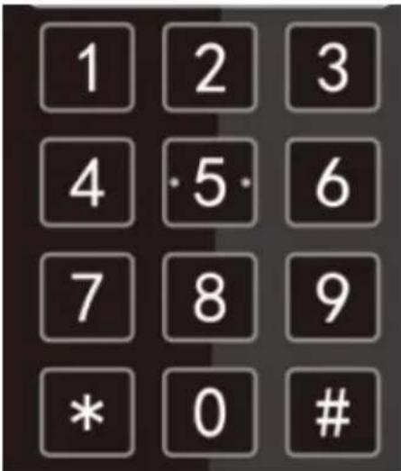
- Number Keys
Set or run 0-9 presets.
-
+ * Keys
Use for key combinations.
- Focus Control Key
Auto Focus: Enter into auto focus mode.
Manual Focus: The camera focus mode is manual
Switch the camera focus mode to manual focus by pressing [focus +] or [focus -] to adjust.
- Zoom Control Key
Zoom +: Zoom In.
Zoom - :Zoom Out.
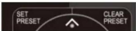
- Set or Clear Preset key:
Set Preset: Sets preset key + 0-9 number key.
Clear Preset: Clears preset key + 0-9 number key.
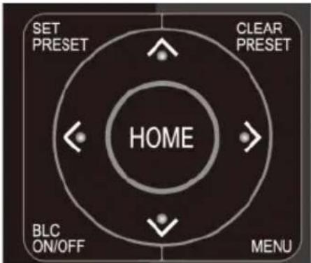
- Pan/Tilt Control Key
Press Key: Tilts camera upwards.
Press ▼Key: Tilts camera downwards.
Press ◀Key: Pans camera left.
Press Key: Pans camera right.
"HOME" Key: Returns camera to the middle position. Also used to enter into the next level menu.
- BLC Control Key
Back Light ON / OFF: Turn on or off the back light.
- Menu Setting
Open or close the on-screen-display menu.
Enter / exit the on-screen-display menu or return to the previous menu.
11. Camera IR Remote Control Address Setting
[ * ] + [ # ] + [ F1 ] : Camera Address No. 1
[ * ]+ [ # ]+[ F2 ] : Camera Address No. 2
[ * ]+ [ # ]+[ F3 ] : Camera Address No. 3
[ * ]+ [ # ]+[ F4 ] : Camera Address No. 4
12. Key Combination Functions
| [ # ] + [ # ] + [ # ]: Clear all presets [ * ] + [ # ] | + [ 6 ]: Restore factory defaults |
| [ * ] + [ # ] + [ 9 ]: Flip switch [ * ] + [ # ] + Auto | to: Enter into the aging mode |
| [ * ] + [ # ] + [ 3 ]: Menu set to Chinese [ * ] + | [ # ] + [ 4 ]: Menu set to English |
| [ * ] + [ # ] + Manual: Restore the defaultuser name, password, and IP address | [ # ] + [ # ] + [ 0 ]:Switch video format to 1080p60 |
| [ # ] + [ # ] + [ 1 ]:Switch video format to 1080p50 | [ # ] + [ # ] + [ 2 ]:Switch video format to 1080i60 |
| [ # ] + [ # ] + [ 3 ]:Switch video format to 1080i50 | [ # ] + [ # ] + [ 4 ]:Switch video format to 720p60 |
| [ # ] + [ # ] + [ 5 ]:Switch video format to 720p50 | [ # ] + [ # ] + [ 6 ]:Switch video format to 1080p30 |
| [ # ] + [ # ] + [ 7 ]:Switch video format to 1080p25 | [ # ] + [ # ] + [ 8 ]:Switch video format to 720p30 |
| [ # ] + [ # ] + [ 9 ]:Switch video format to 720p25 |
3.1.2 Applications
Users can control the pan/tilt/zoom, settings and execute preset positions via the IR remote controller.
Key Instructions:
- In these instructions, “press the key” means a click rather than a long-press. A special note will be given if a long-press for more than one second is required.
- When a key-combination is required, do it in sequence. For example, “[*] + [#] + [F1]” means press [ * ] first, then press [ # ], lastly press { F1 ]
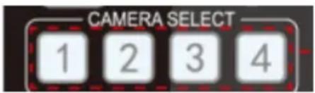
Camera Selection
- Select the camera address to control.
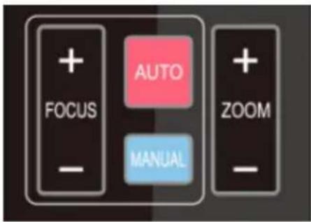
Focus Control
- Focus (near): Press FOCUS + Key (Valid only in manual focus mode)
- Focus (far): Press FOCUS - Key (Valid only in manual focus mode)
- Pressing and holding the "+" or "-" keys will result in the action of focus to continue. Release the key to stop the action of focus.
- Auto Focus: Enables auto focus function.
- Manual Focus: Enables manual focus function.
Zoom Control
- ZOOM IN: Press Zoom + Key
- ZOOM OUT: Press Zoom - Key
- By pressing and holding the key, the camera lens will keep zooming in or zooming out and stops as soon as the key is released.
Preset Setting
- To set a preset position, press the [ SET PRESET ] key first and then press the number key 0-9 to set a relative preset.
- Note: 10 preset positions in total are available by remote controller.
Preset Running
- Press a number key 0-9 directly to run a relative preset.
- Note: Action will not be completed if a relative preset position doesn't exist.
Preset Clearing
- To clear a preset position, press the [CLEAR PRESET] key first and then press the number key 0-9 to clear the relative preset.
- Note: press the [ # ] key three times to clear all presets.
Pan/Tilt Control
Up: Press Down: Press
Left: Press Right: Press


- Back to middle position: Press HOME
- Press and hold the up/down/left/right key to pan or tilt the camera. The camera movement will ease from slow to fast until it reaches the endpoint. The pan/tilt movement stops as soon as the key is released.
BLC ON / OFF
- Enables and/or disables backlight compensation
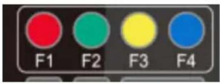
Remote Controller Address Setting
[ * ] + [ # ] + [ F1 ] : Camera Address No. 1
[ * ] + [ # ] + [ F2 ] : Camera Address No. 2
[ * ] + [ # ] + [ F3 ] : Camera Address No. 3
[ * ] + [ # ] + [ F4 ] : Camera Address No. 4
3.2 Menu Setting
3.2.1 Main Menu
In normal working mode, press the MENU key to display the menu. Use the scroll arrow to point at or highlight the selected items.
![MENU Language English (Setup) (Camera) (P/T/Z) (Video Format) (Version) (Restore Default) [↑ ↓ ] Select [← →] Change Value](/content/2026/05/984606/images/76e4f981a7bcf529c6c79f86edfcf2b1e8def2a690f1f3f9e594c4b1d3c77451.jpg)
[ MENU ] Back: Press MENU to Return
[ HOME } OK: Press HOME to Confirm
Language Setting: English / Chinese
Setup: System Settings
Camera: Camera Settings
PTZ: Pan / Tilt / Zoom Settings
Version: Camera Version Settings
Restore Default: Reset Settings
![[↑↓] Select: Menu Selection [←→] Change Value: Modify Parameters](/content/2026/05/984606/images/5ea49fc21fc08aa9161e9ce275d4aeda4875b266c761ea33c546fc67e27ca457.jpg)
3.2.2 System Settings
Move the arrow to the SETUP option in the Main Menu and click the HOME key to enter into the SETUP Settings Menu.
![SETUP ---------------------------------------------------------- Protocol Auto Visca Address 1 Visca Address Fix OFF PELCO-P Address 1 PELCO-D Address 0 Baud Rate 9600 [↑ ↓] Select [← →] Change Value](/content/2026/05/984606/images/4bd19b066c61b420b933e1660fe5dbe5c78668b006306a8689e47670318f558a.jpg)
Protocol: VISCA / PELCO-P / PELCO-D/ AUTO
Visca ADDR: VISCA = 1\~7
PELCO-P = 1\~255
PELCO-D = 1\~255
Visca Address Fix: ON / OFF
Baud Rate: 2400 / 4800 / 9600 / 115200
3.2.3 Camera Settings
Move the arrow to the CAMERA option in the Main Menu and click the HOME key to enter into the CAMERA Settings Menu.
CAMERA
(Exposure)
(Color)
(Image)
(Focus)
(Noise Reduction)


] Select


Change Value
Move the arrow to desired setting (Exposure, Color, etc.) option in the CAMERA menu and click the HOME key to enter.
EXPOSURE
Mode
Auto
EV
OFF
BLC
OFF
Anti-Flicker
50Hz
Gain Limit 3
WDR
5


] Select


Change Value
1. EXPOSURE
- Mode: Auto / Manual / Shutter Priority / Iris Priority / Brightness Priotity
- EV: ON / OFF (Only available in Auto mode)
- Compensation Level: -7\~7 (only available in auto mode when EV is ON)
- BLC: ON/OFF for options (only available in auto mode)
-
Anti-Flicker: OFF/50Hz/60Hz for options (only available in Auto/Iris priority/Brightness priority modes)
-
Gain Limit: 0\~15(only available in Auto/ Iris Priority /Brightness Priority mode)
- WDR: Off, 1\~8
- Shutter Priority: 1/25, 1/30, 1/50, 1/60, 1/90, 1/100, 1/120, 1/180, 1/250, 1/350, 1/500, 1/1000, 1/2000, 1/3000, 1/4000, 1/6000, 1/10000 (only available in Manual and Shutter priority mode)
- IRIS Priority: OFF, F11.0, F9.6, F8.0, F6.8, F5.6, F4.8, F4.0, F3.4, F2.8, F2.4, F2.0, F1.8 (only available in Manual and Iris priority mode)
- Brightness: 0\~23 (only available in Brightness Priority mode)
COLOR
WB Mode Auto
Saturation80%
Hue 7
AWB Sensitivity High
Color Style Default
Color Temp Low
[↑ ↓] Select [← →] Change Value
2. COLOR
- WB Mode: Auto, 3000K, 3500K, 4000K, 4500K, 5000K, 5500K, 6000K, 500K, 7000K, Manual, One Push
- Red Gain: 0\~255(only available in Manual mode)
- Blue Gain: 0\~255(only available in Manual mode)
- Saturation: 60%, 70%, 80%, 90%, 100%, 110%, 120%, 130%
- Hue: 0\~14
- AWB Sensitivity: High/Middle/Low
- Color Style: Default, style1\~4
- Color Temp: High/Middle/Low
IMAGE
Brightness 6
Contrast 8
Sharpness 7
Flip-H OFF
Flip-V OFF
B&W-Mode Color
Gamma Default
DZoom OFF
DCI Close
[↑ ↓] Select [← →] Change Value
3. IMAGE
- Brightness: 0\~14
- Contrast: 0\~14
- Sharpness: 0\~15
- Flip Horizontal: On/Off
- Flip Vertical: On/Off
- B&W Mode: Color, Black/White
- Gamma: default, 0.47, 0.50, 0.52, 0.55
- Digital zoom options: On/Off
- Dynamic Contrast: Off, 1\~8
FOCUS
Focus Mode Auto
AF-Zone Center
AF-Sensitivity Low
[↑ ↓] Select [← →] Change Value
4. FOCUS
- Focus Mode: Auto, Manual
- AF-Zone: Up, Middle, Down
- AF-Sensitivity: High, M=Middle, Low
NOISE REDUCTION
NR-2D
Auto
NR-3D
3
Dynamic Hot Pixel OFF


Select


Change Value
4. NOISE REDUCTION
- 2D Noise Reduction: Auto, Close, 1\~7
- 3D Noise Reduction: Close, 1\~8
- Dynamic Hot Pixel: Close, 1\~5
3.2.4 P/T/Z
Move the arrow to the P/T/Z option in the Main Menu and click the HOME key to enter into the P/T/Z Settings Menu.
P/T/Z
Depth of Field ON
Zoom Speed 8
Image Freezing OFF
Acc Curve Slow


Select


Change Value
- Depth of Field: Only effective for remote controller, On/Off;
- When zoom in, the PT control speed by remoter will become slow),
- Zoom Speed: Set the zoom speed for remote controller, 1\~8
- Image Freezing: On/Off
- Accelerating Curve: Fast/slow
3.2.5 Video Format
Move the arrow to the VIDEO FORMAT option in the Main Menu and click the HOME key to enter into the VIDEO FORMAT Settings Menu.
VIDEO FORMAT
1080P60
1080P50
1080160
1080|50
1080P30
1080P25
720P60
720P50
720P30
720P25
1080P59.94
1080|59.94
1080P29.97
720P59.94
720P29.97


Select
[Menu] Back
- S Version: 1080P60, 1080P50, 1080P30, 1080P25, 1080I60, 1080I50, 720P60, 720P50, 720P30, 720P25, 1080P59.94, 1080I59.94, 1080P29.97, 720P59.94, 720P29.97 Optional - M Version: 1080P30, 1080P25, 1080I60, 1080I50, 720P60, 720P50 Optional
Notes:
- S: 1080P60 Downward Compatibility
- M: 1080P30 Downward Compatibility
- Exiting the menu will save the modification of the parameter. Restart device for parameter modification to be enabled.
3.2.6 Version
Move the arrow to the VERSION option in the Main Menu and click the HOME key to enter into the VERSION Settings Menu.
VERSION
MCU Version 2.0.0.15 2015-12-18
Camera Version 2.0.0.13 2015-12-18
AF Version 2.0.0.6 2015-12-11
Lens 12X (20X)
[Menu] Back
- MCU Version: Display MCU version information
- Camera Version: Display camera version information
- AF Version: Display the focus version information
- Lens: Display the lens zoom
Move the arrow to the RESTORE DEFAULT option in the Main Menu and click the HOME key to enter into the RESTORE DEFAULT Settings Menu.
RESTORE DEFAULT
Restore Default? NO


] Select

→]
Change Value
- Restore default: options: Yes/No; after restoring default, the video format won't be restored.
- Note: If the address of former remote is 2, 3, or 4, the corresponding camera address will restore to 1 when all parameters or system parameters are restored. User should change the remote address to be 1 (press No.1 according to the camera to get normal operation)
4. Network Connection
4.1 Obtain Camera IP Address Based on Auto DHCP
The OTTICA is set to Auto DHCP, so you'll need to obtain camera IP address before connecting to a network. See 2 common solutions to obtain the camera IP address.
Solution 1:
- Connect the camera to a device that can automatically assign an IP address, such as routers and switches.
- Use an IP Search Tool to search LAN segment, such as "192.168.5.0\~192.168.5.255". We suggest using "SoftPerfect Network Scanner" software to get the search results.
- Then search the results and refer to the MAC address pasted on the bottom of the camera to obtain the camera IP address.
Reference Image:
![SoftPerfect Network Scanner [PORTABLE] File View Actions Options Bookmarks Help IPv4 From 192 . 168 . 5 . 0 To 192 . 168 . 5 . 255 Start Scanning IP Address MAC Address Response Time Host Name 192.168.5.22 00-E0-4C-36-0C-94 3 ms bogon 192.168.5.180 8C-EC-4B-D6-1D-20 0 ms LiXiang 192.168.5.190 E4-77-D4-00-D1-6F 0 ms bogon 192.168.5.191 E4-77-D4-04-A2-74 1 ms bogon 192.168.5.192 B8-98-B0-05-B0-0F 1 ms bogon Ready Threads 0 Devices 5 / 5 Scan](/content/2026/05/984606/images/95535e226b2676d4637757049541ab048aa0f2b745792662c5b6a41b0ff83188.jpg)
Solution 2:
- Connect the camera to devices that can automatically assign IP address, such as routers and switches.
- Enter into the Management Interface of the router or switch and obtain the camera IP address with reference to the MAC address pasted on the bottom of the camera.
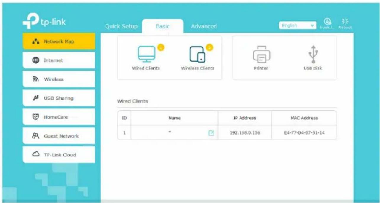
4.2 IE Log In
4.2.1 Web Client
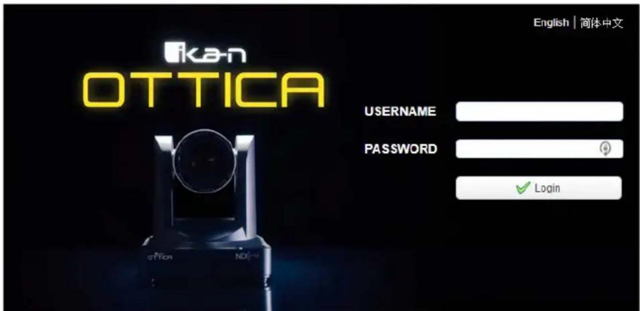
Web Client Log In
- Input the camera IP address (the IP address you obtain through Search Tool) in the address field of your browser and click the "Enter" button to proceed to the Web Client login page.
- You can login as the administrator and normal user. If logging in as an administrator, fill out the required fields with the following: Username: admin. Password: admin.
- Administrator users can preview, playback, cancel, and configure in the Web Client; If logging in as a normal user, the default User name/Password is: user1 or user2. Normal users can only preview playback and cancel. There is no option for configuration.
- NOTE: If you do not have the latest version of Flash installed, click on the button that says "Get ADOBE Flash Player. After you've installed the latest version of flash, the camera feed should be visible and you can now perform PTZ control, video recording, playback, configuration, and other operation
4.2.2 Preview
After successfully logging into the management interface, the video preview interface will become visible. In this interface, users can control pan, tilt, zoom, focus, video capture, sound, full screen, set the preset position, run, delete, and other operations.
4.2.3 Configuration
Click Configuration to enter into the settings page.
There are the following options: Audio Configuration, Video Configuration, Network
Configuration, System Configuration.
4.2.4 Audio Configuration
- Switch: Choose to enable the audio or not.
- Encoding Type: Set the audio compressing format and the device will reboo automatically after the change (default: MP3. optional: PCM & AAC).
- Sample Rate: Set the sampling frequency and the device will reboot automatically after change (default: 48000. Optional: 16000, 32000 and 44100)
- Sampling Bits: Set the sampling precision (Default: 16bits)
- Bit Rate: Set the audio compressing code rate (Default: 64kbps; Optional: 32, 48, 96, 128kbps)
- Channel: Set the audio channel (default: stereo. optional: mono)
- Input Volume: Set the volume level (default: 2). Note: Click “SAVE” and it will remind “Enable has changed. Restart the device to take effect after the success of the save.”, then please reboot the camera to make new setting effect.
4.2.5 Video Configuration
-
Video Encoding
-
Code stream: Stream: Different video output mode settings are available: Main Stream &
- Secondary Stream
- Compression Format: You can set the video compression format. Save and reboot to activate the new format (primary / secondary stream default is set to H.264. H.265 is optional).
- Profile: Profile Mode Setting (default is set to HP. BP & MP are optional).
- Video Size: You can set the video image resolution. Save and reboot to activate the new
format (main stream default: 1080p. 720p is optional).
- Stream Rate control: You can set the rate control mode. Save and reboot to activate the new mode (primary / secondary stream default is set to Variable Rate. Fixed rate is optional).
- Image Quality: You can set the image quality. The image quality can be changed only when the stream rate control is set to Variable Rate.
- Bit Rate (Kb/s): You can set the video bit rate
(Main stream default: 4096kb/s. Optional: 64-12288kb/s)
(Secondary stream default: 1024kb/s. Optional: 64-10240kb/s)
- Frame Rate (fps): Set the video frame rate (primary / secondary stream default is 25fps. primary stream 5-60fps is optional, secondary stream 5-30fps is optional).
- Frame Interval: You can set the key frame interval (primary / secondary stream default setting is 75f. Primary / stream 1-300f is optional. Secondary stream 1-150F is optional).
- Stream Name: When streaming via rtsp or rtmp, you can modify the stream name. Main Stream (live/av0), sub stream (live/av1)
- Click the “Save” button to display the “saved successfully” message. The new settings will then be activated.
- Switch: To turn on/off the main / secondary stream.
- Protocol: Primary / secondary stream applies RTMP protocol.
- Host Port: Server port number (Default: 1935; Optional: 0-65535) Host Address: Server IP addresses (Default: 192.168.5.11)
- Stream Name: Choose a different stream name (live / av0, live / av1 optional).
-
User: Set the user name.
-
Stream Publish
-
Switch: To turn on/off the main / sub stream.
- Protocol Type: Primary / secondary stream applies RTMP protocol.
- Host Address: Server IP addresses (Default: 192.168.5.11)
- Host Port: Server port number (Default 1935: Optional: 0-65535)
- Stream Name: Choose a different stream name (live / av0, live / av1 optional).
- User Name: Set the user name.
- Password: Set the password.
- Click on the “Save” button to display the “Save successful” message. The new settings will then be activated.
-
Method of obtaining RTSP: rtsp: // device IP address: 554 / live / av0 (av0 main stream; av1 secondary stream).
-
Multicast
-
Switch: To turn on/off the main / sub stream.
- Protocol Type: RTP or TS
- Multicast Address: Default 224.1.2.3. (Can be edited)
- Multicast Port: Main Stream Default Port: 4000, Sub Stream Default Port: 4002
4. Video Parameters
A. Focus Settings
- Focus Mode: Auto (default), Manual & OnePush (optional).
- AF-Zone: All (default), Top, Center, Bottom (optional).
- Focus Sensitivity: Low (default), High & Medium (optional).
B. Exposure
- Mode: Auto (default), Manual, SAE, AAE, Bright (optional). Shutter Priority, Aperture Priority, Brightness Priority (optional).
- Exposure Compensation: Exposure Compensation settings are activated only when
- EV: Off (default), On (optional)
- EV Level: 0 (default) -7 through 7 (optional)
- BLC: Settings are activated only when Exposure Mode is set to Automatic (Default: OFF).
- Flicker: Settings are activated only when Exposure Mode is set to Automatic, Aperture, or Brightness Priority. (Default: 50Hz. Optional: Off & 60Hz).
- Gain Limit: (Default: 3; Optional: 0-15).
- Dynamic Range: (Default: 4; Optional: 0-8).
- Shutter Speed: Settings are activated only when Exposure Mode is set to Manual or Shutter-Priority (Default: 1/100. Optional: 1/25, 1/30, 1/50, 1/60, 1/90, 1/100, 1/120, 1/180, 1/250, 1/350, 1/500, 1/1000, 1/2000, 1/3000, 1/4000, 1/6000, 1/10000).
- Iris: Settings are activated only when Exposure Mode is set to Manual or Aperture-Priority (Default: F1.8; Optional: Closed, F1, F9.6, F8.0, F6.8, F5.6, F4.8, F4.0, F3.4, F2.8, F2.4, F2.0, F1.8).
- Brightness: Settings are activated only when Exposure Mode is set to Brightness Priority (Default: 7; Optional: 0-23).
C. Color
- White Balance Modes: (Default: Automatic; Optional: Manual, OnePush, Variable)
- Variable Color Temperatures: 2400K - 7100K
- Red Gain: (Default: 255; Optional: 0-255).
- Blue Gain: (Default: 199; Optional: 0-255).
- Saturation: (Default: 100%; Optional: 60%, 70%, 80%, 90%, 110%, 120%, 130%).
- Hue: (Default: 7; Optional: 0-14).
- Auto White Balance Sensitivity: (Default: High; Optional: Low & Medium)
D. Image
- Brightness: (Default: 6; Optional: 0-14).
- Contrast: (Default: 8; Optional: 0-14).
- Sharpness: (Default: 7; Optional: 0-15).
- Black and White Mode: (Default: Color; Optional: Black & White).
- Gamma: (Default: 0.45; Optional: 0.50, 0.52, 0.55).
-
Flip Horizontal: (Default: OFF; Optional: ON).
-
Flip Vertical: (Default: OFF; Optional: ON).
- DCI: (Default: OFF; Optional: ON).
- DZoom: (Default: OFF; Optional: ON).
- Low-Light Mode: (Default: OFF; Optional: ON).
E. Noise Reduction
- 2D Noise Reduction: (Default: 1; Optional: 2-7, AUTO, and OFF).
- 3D Noise Reduction: (Default: 3; Optional: 1-8 and OFF).
- Dynamic Dead Pixel Correction: (Default: OFF; Optional: 1-5).
F. Style
- Style Option: (Default: Default; Optional: Normal, Clarity, Bright, Soft)
4. Character-Overlapping
- Display Date and Time: Set whether to display the time and date (default display).
- Display Title: Set whether to display the title (default display).
- Font Color of Time: (Default: White; Optional: Black, Yellow, Red, Blue).
- Font Color of Title: (Default: White; Optional: Black, Yellow, Red, Blue).
- Moving Characters: You can set the display position of moving date, time and title, click on the "Up, Down, Left, Right" buttons to move the corresponding character position.
- Title Content: You can set Title Content (default is set to CAMERA1).
- Time Content: You can set Time Content (default is set to 1970/01/10 05:36:00).
- After clicking on the “Save” button, the “Save Successful” message will be displayed. Your selected time settings will now be visible.
5. Character Size
- Switch: Enable "Scale Size Automatically" funtion.
- Master Stream OSD Font Size: Set the character size of the display, the device will restart automatically after changed and saved (Default: 48).
- Slave Stream OSD Font Size: You can set the Character Size on the display. The device will restart automatically after changed and saved (Default: 48).
- After clicking on the "Save" button, the configuration will be validated when you see the "Parameter Saved Successfully" message displayed.
6. Video Output
- Default: 1080P29.97
- Optional: 1080P60, 1080P50, 1080P30, 1080P25, 1080I60, 1080I50, 720P60, 720P50, 720P30, 720P25, 1080P59.94, 1080I59.94, 720P59.94, 720P29.97
- By clicking on the "Save" button, the configuration will be validated when you see the "Save successful" message displayed.
4.2.6 Network Configuration
1. Network Port
- Data port: You can set the Data Port. The device will restart automatically after it's changed (Default: 3000; Optional: 0-65535).
- Web Port: You can set the Web Port. The device will restart automatically after changed (Default: 80; Optional: 0-65535).
- Onvif Port: You can set the Onvif Port. The device will restart automatically after changed (Default: 2000; Optional: 0-65535).
- Soap Port: You can set the Soap Port (Default: 1936; Optional: 0-65535).
- RTMP Port: You can set the RTMP Port (Default: 1935; Optional: 0-65535).
- RTSP Port: You can set the RTSP Port. The device will restart automatically after changed (Default: 554; Optional: 0-65535).
- Visca Port: You can set the Visca Port. The device will restart automatically after changed (Default: 1259; Optional: 0-65535).
- By clicking on the “Save” button, the configuration will be validated when you see the display message: “Save successful”.
- RTMP access: RTMP: // equipment IP address: 1935 / live/av0 (av0 main stream; av1 second stream)
- RTMP Access: rtmp://equipment IP address: 1935 / live/av0 (av0 main stream; av1 second stream)
2. Ethernet Parameters
- DHCP: Enable or disable the option to obtain IP automatically can be set. By clicking on the "Save" button and rebooting the device, a display saying "Save successful" will be shown. The configuration will now be validated (Default is set to ON).
- IP Address: You can set the IP Address. By clicking on the “Save” button and rebooting the device, a display saying “Save successful” will be shown. The configuration will now be validated. (Default is now set to 192.168.5.163). Note: This IP address is the same with the one used to login to the web page.
- Subnet Mask: You can set the Subnet Mask (Default is set to 255.255.255.0).
- Default Gateway: You can set the Default Gateway (Default is set to 0.0.0.0).
- MAC Address: You can set the Physical Address (The parameter is read-only and can not be modified).
- By clicking on the “Save” button, the configuration will be validated when you see the display message: “Save successful”.
3. DNS Parameters
- Preferred DNS Server: You can set the preferred DNS server (Default is set to 0.0.0.0).
- Alternate DNS Server: Alternate DNS server settings (Default is set to 0.0.0.0).
- By clicking on the “Save” button, the configuration will be validated when you see the display message: “Save successful”.
4. NDI
- Switch: Set NDI function on or off.
NDI Name: User can change the NDI Name
NDI Group: User can change the NDI Group
- By clicking on the “Save” button, the configuration will be validated when you see the display message: “Save successful”.
4.2.7 System Configuration
1. System Attributes
- Device Name: Set the device name (Default is CAMERA-1. User can create their own).
- Device ID: Set the device ID (default is set to 1. Read-Only).
- System Language: Set the system language (Default: English; Optional: Simplified Chinese). Re-login after modification and save the setting.
- By clicking on the “Save” button, the configuration will be validated when you see the display message: “Save successful”
2. System Time
- Date Format: You can set the Date Format (YYYY-MM-DD).
- Date Separator: (Default: “/” Optional: “.” and “-”).
- Time Zone: You can set the Time Zone.
- Hour Type: (Default: 24 hours; Optional: 12 hours).
- NTP Enable: Click the checkbox to turn the "NTP Enable" function on or off.
- Update Interval: You can set the NTP server to automatically update the time interval. Valid after setting NTP server synchronization (Default: One Day; Optional: 2-10 days).
- Host URL: You can set NTP server address or domain name (default time.nits.gov). Valid after setting NTP server synchronization.
- Host Port: You can set the NTP server port (Default: 123). Valid after setting NTP server synchronization.
- Set the time manually. Effective when set manually.
- Time Setting: You can set the Time Mode (choose the computer time synchronization, NTP server time synchronization, or set manually).
- Computer Time: You can set the Computer Time.
- By clicking on the "Save" button, the configuration will be validated when you see the display message: "Save successful".
3. User Settings
- Authority: You can set the User Type (the default is set to Administrator. Common User 1, Common User 2 are optional)
- User name: You can set the User Name (Select User Administrator default admin; select a common user1 default user1; to select a common user 2 default user2; user can modify their own)
- Password: You can set a Password (Select User Administrator default admin; select a common user1 default user1; to select a common user 2 default user2; user can modify their own).
- Password Confirmation: Confirm the input passwords are the identical.
- By clicking on the "Save" button, the configuration will be validated when you see the display message: "Save successful".
- Note: User name and Password are case-sensitive.
4. Version Upgrade
MCU version V2.0.0.16 2015-12-18
Camera version V2.0.0.16 2015-12-18
Focus version V2.0.0.6 2015-12-11.
Update File:
- Click "Browse ..." installation, to select the upgrade file in the pop-up window.
- Click on the “Upgrade” button. The upgrade dialog will appear. The device will reboot automatically after the update is successful. Make sure the power and network remains connected during the upgrading process.
- Note: If you need to restore factory defaults, choose one of the three options:
A. Through web to restore the factory default configuration.
B. Through the recovery menu.
C. Remote control shortcut: * # 6.
5. Restore Factory Setting
- Click on “Restore Factory Defaults” button and choose “yes” or “no”, then the device will restart automatically and restore factory setting.
6. Reboot
- Click on the "Reboot" button and choose "yes" or "no".
- The device will restart automatically.
4.2.8 Logout
Click “Logout.” When the pop-up “Confirmation” dialog appears, select “Yes” or “No”. Choose “Yes” to exit the current page and return to the user login interface again.
4.2.9 Wireless Network
If the user's equipment has a wireless network module, the web page "Network Configuration" has a "Wireless Network" configuration page. The specific configuration is as follows:
1. Network Settings
Wireless Network Configuration
- Enable Network Interface: You can check, to set the following items after checked.
- DHCP: If checked, it can obtain IP automatically.
- IP address: set wireless WIFI IP (default is set to 192.168.1.250. If checked DHCP, IP will be assigned automatically).
Note: Wireless IP address cannot be in the same segment with wired IP address.
- Subnet Mask: You can set the wireless IP subnet mask (Default: 255.255.255.0)
- Default Gateway: You can set the wireless IP default gateway (Default: 192.168.1.1)
- SSID: The user can modify their own (the default test).
- Encryption: Able to be checked. The password can be set after checked.
- Password: You can set the password. Password can be changed only if encryption is checked.
After clicking on the "Save" button, character settings will be validated when the "Parameter Saved Successfully" message is displayed.
Note: SSID and password should be filled in correctly; otherwise, if restarted after powered off, the wireless Wi-Fi connection will not be successful.
2. Wi-Fi Hot Link
- Click on the "search" button to search the WIFI hotspot.
- Double-click the dialog box after you've searched the user WIFI hotspot. Then input password to connect to WIFI. It will connect successfully after showing the “Successful Connect” window.
3. Wireless Wi-Fi Login Page
- If you do not check the above DHCP configuration (automatically obtain IP), then open the browser, enter the wireless network IP address in the address bar (Default: 192.168.1.250), press Enter to log construction.
- If you checked DHCP, then you will obtain IP automatically, just login specific router or switch user interface settings to view the allocation of IP address.
5. Serial Communication Control
Under common working condition, the camera could be controlled through RS232/RS485
interface (VISCA), RS232C serial parameter are as follows:
Baud rate: 2400/4800/9600/115200 bits / sec;
Start bit: 1; data bits: 8; Stop bit: 1; Parity: None.
5.1 VISCA Protocol List
5.1.1 Camera Return Command
| ACK/Completion Message | ||
| Command Packet Note | ||
| ACK z0 41 FF Returned when the command is accepted. | ||
| Completion z0 51 FF Returned when the command has been executed. | ||
| Error Messages | ||
| Command Packet Note | ||
| Syntax Error z0 60 | 02 FF Returned when | the command format is different or when a command with illegal command parameters is accepted |
| Command Not Executable | z0 61 41 FF Returned | when a command cannot be executed due to current conditions. For example,when commands controlling the focus manually are received during auto focus. |
5.1.2 Camera Control Command
| Command Function | Command Packet | Notes | |
| AddressSet Broadcast | 88 30 0p FF p: Address setting | ||
| IF_Clear Broadcast 88 | 01 00 01 FF I/F Clear | ||
| CommandCancel 8x 21 | FF | ||
| CAM_Power | On 8x 01 04 00 | 02 FF | Power ON/OFF |
| Off 8x 01 04 00 | 03 FF | ||
| CAM_Zoom | Stop 8x 01 04 07 | 00 FF | |
| Tele(Standard) 8x | 01 04 07 02 FF | ||
| Wide(Standard) | 8x 01 04 07 03 FF | ||
| Tele(Variable) | 8x 01 04 07 2p FF | p = 0(low) - F(high) | |
| Wide(Variable) 8x | 01 04 07 3p FF | ||
| Direct | 8x 01 04 47 0p 0q 0r 0s FF | pqrs: Zoom Position | |
| CAM_Focus | Stop 8x 01 04 08 | 00 FF | |
| Far(Standard) | 8x 01 04 08 02 FF | ||
| Near(Standard) | 8x 01 04 08 03 FF | ||
| Far(Variable) | 8x 01 04 08 2p FF | p = 0(low) - F(high) | |
| Near (Variable) | 8x 01 04 08 3p FF | ||
| Direct | 8x 01 04 48 0p 0q 0r 0s FF | pqrs: Focus Position | |
| Auto Focus | 8x 01 04 38 02 FF | ||
| One Push Mode | 8x 01 04 38 04 FF | ||
| Manual Focus | 8x 01 04 38 03 FF | ||
| CAM_Zoom Focus | Direct | 8x 01 04 47 0p 0q 0r 0s 0t 0u 0v 0w FF | pqrs: Zoom Position tuvw: Focus Position |
| CAM_WB | Auto 8x 01 04 35 | 00 FF | |
| 3000K | 8x 01 04 35 01 FF | ||
| 4000k | 8x 01 04 35 02 FF | ||
| One Push Mode | 8x 01 04 35 03 FF | ||
| 5000k | 8x 01 04 35 04 FF | ||
| CAM-WB(continued) | Manual 8x 01 04 | 35 05 FF | |
| 6500k 8x 01 04 | 35 06 FF | ||
| 3500K 8x 01 04 | 35 07 FF | ||
| 4500K 8x 01 04 | 35 08 FF | ||
| 5500K 8x 01 04 | 35 09 FF | ||
| 6000K 8x 01 04 | 35 0A FF | ||
| 7000K 8x 01 04 | 35 0B FF | ||
| CAM_RGain | Reset 8x 01 04 03 00 FF | Manual Control of R GainUp | |
| Down 8x 01 04 03 03 FF | |||
| Direct | 8x 01 04 43 00 00 0p 0q FF | pq: R Gain | |
| CAM_Bgain | Reset 8x 01 04 04 00 FF | Manual Control of B GainUp | |
| Down 8x 01 04 04 03 FF | |||
| Direct | 8x 01 04 44 00 00 0p 0q FF | pq: B Gain | |
| CAM_AE | Full Auto 8x 01 04 39 00 FF Automatic Exposure mode | ||
| Manual 8x 01 04 39 03 FF Manual Control mode | |||
| Shutter priority 8x 01 04 39 0A FF | Shutter Priority Automatic Exposure mode | ||
| Iris Priority 8x 01 04 39 0B FF | Iris Priority Automatic Exposure mode | ||
| Bright 8x 01 04 39 0D FF Bright mode | |||
| CAM_Shutter | Reset 8x 01 04 0A 00 FF | Shutter Setting | |
| Up 8x 01 04 0A 02 FF | |||
| Down 8x 01 04 0A 03 FF | |||
| Direct | 8x 01 04 4A 00 00 0p 0q FF | pq: Shutter Position | |
| CAM_Iris | Reset 8x 01 04 0B 00 FF | Iris Setting | |
| Up 8x 01 04 0B 02 FF | |||
| Down 8x 01 04 0B 03 FF | |||
| Direct | 8x 01 04 4B 00 00 0p 0q FF | pq: Iris Position | |
| CAM_Gain Limit | Gain Limit | 8x 01 04 2C 0p FF p: Gain Position | |
| CAM_Bright | Reset 8x 01 04 0D 00 FF | Bright SettingUp 8x 01 04 0D 02 FI | |
| Down 8x 01 04 0D 03 FF | |||
| Direct | 8x 01 04 4D 00 00 0p 0q FF | pq: Bright Positon | |
| CAM_ExpComp | On 8x 01 04 3E 02 FF | Exposure Compensation ON/OFF | |
| Off 8x 01 04 3E 03 FF | |||
| Reset 8x 01 04 0E 00 FF | Exposure Compensation Amount Setting | ||
| Up 8x 01 04 0E 02 FF | |||
| Down 8x 01 04 0E 03 FF | |||
| Direct | 8x 01 04 4E 00 00 0p 0q FF | pq: ExpComp Position | |
| CAM_Back Light | On 8x 01 04 33 02 FF | Back Light Compensation | |
| Off 8x 01 04 33 03 FF | |||
| CAM_WDRStrength | Reset 8x 01 04 21 00 FF | WDR Level SettingUp 8x 01 04 21 0 | |
| Down 8x 01 04 21 03 FF | |||
| Direct | 8x 01 04 51 00 00 00 0p FF | p: WDR Level Positon | |
| CAM_NR (2D) 8x 01 04 53 0p FF P=0-7 0:OFF | |||
| CAM_NR (3D) 8x 01 04 54 0p FF P=0-8 0:OFF | |||
| CAM_Gamma 8x 01 04 5B 0p FF | p = 0 - 40: Default1: 0.472: 0.503: 0.524: 0.55 | ||
| CAM_Flicker | OFF 8x 01 04 23 00 FF OFF | ||
| 50HZ 8x 01 04 23 01 FF 50HZ | |||
| 60HZ 8x 01 04 23 02 FF 60HZ | |||
| CAM_Aperture | Reset 8x 01 04 02 00 FF | Aperture ControlUp 8x 01 04 02 02 | |
| Down 8x 01 04 02 03 FF | |||
| Direct | 8x 01 04 42 00 00 0p 0q FF | pq: Aperture Gain | |
| CAM_Memory | Reset 8x 01 04 | 3F 00 pq FF pq: Memory | Number(=0 to 254)Corresponds to 0 to 9 on the Remote Commander |
| Set 8x 01 04 3F | 01 pq FF | ||
| Recall 8x 01 04 | 3F 02 pq FF | ||
| CAM_LR_Reverse | On 8x 01 04 61 | 02 FF | Image Flip Horizontal ON/OFF |
| Off 8x 01 04 61 | 03 FF | ||
| CAM_PictureFlip | On 8x 01 04 66 | 02 FF | Image Flip Vertical ON/OFF |
| Off 8x 01 04 66 | 03 FF | ||
| CAM_ColorSaturation | Direct | 8x 01 04 49 00 00 00 0p FF | P=0-70:60% 1:70% 2:80%3:90% 4:100% 5:110%6:120% 7:130% |
| CAM_IDWrite | 8x 01 04 22 0p 0q 0r 0s FF | pqrs: Camera ID (=0000 to FFFF) | |
| SYS_Menu | ON 8x 01 04 06 | 06 02 FF Turn on the menu screen | |
| OFF 8x 01 04 06 | 06 03 FF Turn off the menu screen | ||
| IR_Receive | ON 8x 01 06 08 | 02 FF | IR (remote commander) receive On/Off |
| OFF 8x 01 06 08 | 03 FF | ||
| IR_ReceiveReturn | On | 8x 01 7D 01 03 00 00 FF | IR(remote commander) receive message via the VISCA communication ON/OFF |
| Off | 8x 01 7D 01 13 00 00 FF | ||
| CAM_SettingvReset Reset | 8x 01 04 A0 | 10 FF Reset Factory Setting | |
| CAM_Brightness | Direct | 8x 01 04 A1 00 00 0p 0q FF | pq: Brightness Position |
| CAM_Contrast | Direct | 8x 01 04 A2 00 00 0p 0q FF | pq: Contrast Position |
| CAM_Flip | OFF 8x 01 04 A4 | 00 FF | Single Command For Video Flip |
| Flip-H | 8x 01 04 A4 01 FF | ||
| Flip-V | 8x 01 04 A4 02 FF | ||
| Flip-HV | 8x 01 04 A4 03 FF | ||
| CAM_VideoSystem | Set camera video system | 8x 01 06 35 00 0p FF | P: 0~E Video Format0:1080P60 5:720P501:1080P50 6:1080P302:1080i60 7:1080P253:1080i50 8:720P304:720P60 9:720P25A: 1080P59.94B: 1080i59.94C: 720P59.94D: 1080P29.97E: 720P29.97 |
| Pan_tiltDrive | Up | 8x 01 06 01 VV WW03 01 FF | VV: Pan speed0x01 (low speed) to0x18 (high speed)WW: Tilt speed 0x01(low speed) to 0x14 (high speed)YYYY: Pan PositionZZZZ: Tilt Position |
| Down | 8x 01 06 01 VV WW03 02 FF | ||
| Left | 8x 01 06 01 VV WW01 03 FF | ||
| Right | 8x 01 06 01 VV WW02 03 FF | ||
| Upleft | 8x 01 06 01 VV WW01 01 FF | ||
| Upright | 8x 01 06 01 VV WW02 01 FF | ||
| DownLeft | 8x 01 06 01 VV WW01 02 FF | ||
| DownRight | 8x 01 06 01 VV WW02 02 FF | ||
| Stop | 8x 01 06 01 VV WW03 03 FF | ||
| AbsolutePosition | 8x 01 06 02 VV WW0Y 0Y 0Y 0Z 0Z 0Z 0Z FF | ||
| RelativePosition | 8x 01 06 03 VV WW0Y 0Y 0Y 0Z 0Z 0Z 0Z FF | ||
| Home 8x 01 06 | 04 FF | ||
| Reset 8x 01 06 | 05 FF | ||
| Pan-tiltLimitSet | Set | 8x 01 06 07 00 0W0Y 0Y 0Y 0Y 0Z 0Z 0Z0Z FF | W:1 UpRight 0:DownLeftYYYY: Pan Limit Position(TBD)ZZZZ: Tilt Limit Position(TBD) |
| Clear | 8x 01 06 07 01 0W07 0F 0F 0F 07 0F 0F0F FF | ||
5.1.3 Inquiry Command
| Command Function Command Packet Notes | |||
| CAM_PowerInq 8x 09 04 00 | FF | y0 50 02 FF On | |
| y0 50 03 FF Off(Standby) | |||
| CAM_ZoomPosInq 8x 09 04 | 47 FF y0 50 0p 0q | Or 0s FF pqrs: Zoom Position | |
| CAM_FocusAFModelInq 8x 09 | 04 38 FF | y0 50 02 FF Auto Focus | |
| y0 50 03 FF Manual Focus | |||
| y0 50 04 FF One Push Mode | |||
| CAM_FocusPosInq 8x 09 04 | 48 FF y0 50 0p 0q | Or 0s FF pqrs: Focus Position | |
| CAM_WBModelInq 8x 09 04 | 35 FF | y0 50 00 FF Auto | |
| y0 50 01 FF 3000K | |||
| y0 50 02 FF 4000K | |||
| y0 50 03 FF One Push Mode | |||
| y0 50 04 FF 5000K | |||
| y0 50 05 FF Manual | |||
| y0 50 00 FF 6500K | |||
| y0 50 06 FF 6500K | |||
| y0 50 07 FF 3500K | |||
| y0 50 08 FF 4500K | |||
| y0 50 09 FF 5500K | |||
| y0 50 0A FF 6000K | |||
| y0 50 0B FF 7000K | |||
| CAM_RGainInq 8x 09 04 43 | FF y0 50 00 00 0p | 0q FF pq: R Gain | |
| CAM_BGainInq 8x 09 04 44 | FF y0 50 00 00 0p | 0q FF pq: B Gain | |
| CAM_AEModelnq 8x 09 04 39 FF | y0 50 00 FF Full Auto | ||
| y0 50 03 FF Manual | |||
| y0 50 0A FF Shutter Priority | |||
| y0 50 0B FF Iris Priority | |||
| y0 50 0D FF Bright | |||
| CAM_ShutterPosInq | 8x 09 04 4A FF | y0 50 00 00 0p 0q FF pq: Shutter Position | |
| CAM_IrisPosInq | 8x 09 04 4B FF | y0 50 00 00 0p 0q FF pq: Iris Position | |
| CAM_Gain LimitInq | 8x 09 04 2C FF | y0 50 0p FF p: Gain Positon | |
| CAM_BrightPosInq | 8x 09 04 4D FF | y0 50 00 00 0p 0q FF pq: Bright Position | |
| CAM_ExpCompModelnq 8x 09 04 3E FF | y0 50 02 FF On | ||
| y0 50 03 FF Off | |||
| CAM_ExpCompPosInq 8x 09 04 4E FF y0 50 00 00 0p 0q FF pq: ExpComp Position | |||
| CAM_BacklightModelnq 8x 09 04 33 FF | y0 50 02 FF On | ||
| y0 50 03 FF Off | |||
| CAM_WDRStrengthInq 8x 09 04 51 FF y0 50 00 00 00 0p FF p: WDR Strength | |||
| CAM_NRLevel(2D) Inq | 8x 09 04 53 FF | y0 50 0p FF P: 2DNRLevel | |
| CAM_NRLevel(3D) Inq | 8x 09 04 54 FF | y0 50 0p FF P:3D NRLevel | |
| CAM_FlickerModelnq | 8x 09 04 55 FF | y0 50 0p FF | p: Flicker Settings(0:OFF,1: 50Hz,2:60Hz) |
| CAM_ApertureInq | 8x 09 04 42 FF | y0 50 00 00 0p 0q FF | pq: Aperture Gain |
| CAM_PictureEffectModelnq 8x 09 04 63 FF | y0 50 00 FF Off | ||
| y0 50 04 FF B&W | |||
| CAM_MemoryInq 8x 09 04 3F FF y0 50 0p FF | p: Memory number last operated. | ||
| SYS_MenuModelnq | 8x 09 06 06 FF | y0 50 02 FF On | |
| y0 50 03 FF Off | |||
| CAM_LR_Reverselnq | 8x 09 04 61 FF | y0 50 02 FF On | |
| y0 50 03 FF Off | |||
| CAM_PictureFlipInq | 8x 09 04 66 FF | y0 50 02 FF On | |
| y0 50 03 FF Off | |||
| CAM_ColorSaturationInq 8x 09 04 49 FF y0 50 00 00 00 p FF | p: Color Gain setting 0h (60%) to Eh (130%) | ||
| CAM_IDInq 8x 09 04 22 FF y0 50 0p FF p: Gamma ID | |||
| IR_ReceiveInq 8x 09 06 08 FF | y0 50 02 FF On | ||
| y0 50 03 FF Off | |||
| IR_ReceiveReturn | y0 07 7D 01 04 00 FF Power ON/OFF | ||
| y0 07 7D 01 04 07 FF Zoom tele/wide | |||
| y0 07 7D 01 04 38 FF AF ON/OFF | |||
| y0 07 7D 01 04 33 FF Camera _Backlight | |||
| y0 07 7D 01 04 3F FF Camera _Memory | |||
| y0 07 7D 01 06 01 FF Pan_titleDriver | |||
| CAM_BrightnessInq 8x 09 04 A1 FF y0 50 00 00 0p 0q FF | pq: Brightness Position | ||
| CAM_ContrastInq 8x 09 04 A2 FF y0 50 00 00 0p 0q FF pq: Contrast Position | |||
| CAM_FlipInq 8x 09 04 A4 FF | y0 50 00 FF Off | ||
| y0 50 01 FF Flip-H | |||
| y0 50 02 FF Flip-V | |||
| y0 50 03 FF Flip-HV | |||
| CAM_Gammalnq | 8x 09 04 5B FF | y0 50 0p FF p: Gamma setting | |
| CAM_VersionInq | 8x 09 00 02 FF | y0 50 ab cd mn pq rs tu vw FF | ab cd:- vendor ID (0220)mn pq:- model ID ST (0950)U3 (3950)rs tu:- ARM Versionvw:- Reserve |
| Command Function Command Packet Notes | |||
| VideoSystemInq 8x 09 06 23 | FF y0 50 0p FF | P: 0~E Video format0:1080P601:1080P502:1080i603:1080i504:720P605:720P506:1080P307:1080P258:720P309:720P25A: 1080P59.94B: 1080i59.94C: 720P59.94D: 1080P29.97E: 720P29.97 | |
| Pan-tiltMaxSpeedInq 8x 09 06 11 FF y0 50 ww zz FF | ww: Pan Max Speedzz: Tilt Max Speed | ||
| Pan-tiltPosInq 8x 09 06 12 FF | y0 50 0w 0w 0w 0w0z 0z 0z 0z FF | www: Pan Positionzzzz: Tilt Position | |
5.2 Pelco-D Protocol Command List
| Function Byte | 1 Byte2 | Byte3 Byte4 | Byte5 Byte6 Byte7 | ||||
| Up | 0xFF | Address | 0x00 | 0x08 | Pan Speed | Tilt Speed | SUM |
| Down | 0xFF | Address | 0x00 | 0x10 | Pan Speed | Tilt Speed | SUM |
| Left | 0xFF | Address | 0x00 | 0x04 | Pan Speed | Tilt Speed | SUM |
| Right | 0xFF | Address | 0x00 | 0x02 | Pan Speed | Tilt Speed | SUM |
| Upleft | 0xFF | Address | 0x00 | 0x0C | Pan Speed | Tilt Speed | SUM |
| Upright | 0xFF | Address | 0x00 | 0x0A | Pan Speed | Tilt Speed | SUM |
| DownLeft | 0xFF | Address | 0x00 | 0x14 | Pan Speed | Tilt Speed | SUM |
| DownRight | 0xFF | Address | 0x00 | 0x12 | Pan Speed | Tilt Speed | SUM |
| Zoom In | 0xFF | Address | 0x00 | 0x20 | 0x00 | 0x00 | SUM |
| Zoom Out | 0xFF | Address | 0x00 | 0x40 | 0x00 | 0x00 | SUM |
| Focus Far | 0xFF | Address | 0x00 | 0x80 | 0x00 | 0x00 | SUM |
| Focus Near | 0xFF | Address | 0x01 | 0x00 | 0x00 | 0x00 | SUM |
| Function Byte1 | Byte2 | Byte3 | Byte4 | Byte5 | Byte6 | Byte7 | |||
| Set Preset 0xFF | Address | 0x00 | 0x03 | 0x00 | Preset ID SUM | ||||
| Clear Preset 0xFF | Address | 0x00 | 0x0 | 5 | 0x00 Preset ID SUM | ||||
| Call Preset 0xFF | Address | 0x00 | 0x07 | 0x00 | Preset ID SUM | ||||
| Query Pan Position | 0xFF Address | 0x00 | 0x51 | 0x00 | 0x00 SUM | ||||
| Query Pan Position Response | 0xFF Address | 0x00 | 0x59 | Value High Byte | Value Low Byte | SUM | |||
| Query Tilt Position | 0xFF Address | 0x00 | 0x53 | 0x00 | 0x00 SUM | ||||
| Query Tilt Position Response | 0xFF Address | 0x00 | 0x5B | Value High Byte | Value Low Byte | SUM | |||
| Query Zoom Position | 0xFF Address | 0x00 | 0x55 | 0x00 | 0x00 SUM | ||||
| Query Zoom Position Response | 0xFF Address | 0x00 | 0x5D | Value High Byte | Value Low Byte | SUM | |||
5.3 Pelco-P Protocol Command List
| Function | Byte1 | Byte2 | Byte3 | Byte4 | Byte5 | Byte6 | Byte7 | Byte8 |
| Up | 0xA0 | Address | 0x00 | 0x08 | Pan Speed | Tilt Speed | 0xAF | XOR |
| Down | 0xA0 | Address | 0x00 | 0x10 | Pan Speed | Tilt Speed | 0xAF | XOR |
| Left | 0xA0 | Address | 0x00 | 0x04 | Pan Speed | Tilt Speed | 0xAF | XOR |
| Right | 0xA0 | Address | 0x00 | 0x02 | Pan Speed | Tilt Speed | 0xAF | XOR |
| Upleft | 0xA0 | Address | 0x00 | 0x0C | Pan Speed | Tilt Speed | 0xAF | XOR |
| Upright | 0xA0 | Address | 0x00 | 0x0A | Pan Speed | Tilt Speed | 0xAF | XOR |
| DownLeft | 0xA0 | Address | 0x00 | 0x14 | Pan Speed | Tilt Speed | 0xAF | XOR |
| DownRight | 0xA0 | Address | 0x00 | 0x12 | Pan Speed | Tilt Speed | 0xAF | XOR |
| Zoom In | 0xA0 | Address | 0x00 | 0x20 | 0x00 | 0x00 | 0xAF | XOR |
| Zoom Out | 0xA0 | Address | 0x00 | 0x40 | 0x00 | 0x00 | 0xAF | XOR |
| Focus Far | 0xA0 | Address | 0x01 | 0x00 | 0x00 | 0x00 | 0xAF | XOR |
| Focus Near | 0xA0 | Address | 0x02 | 0x00 | 0x00 | 0x00 | 0xAF | XOR |
| Function Byte | 1 Byte2 | Byte3 Byte | 4 Byte | 5 Byte6 | Byte7 Byte8 | |||
| Set Preset 0xA0 Address 0x00 0x03 0x00 Preset ID 0xAF XOR | ||||||||
| Clear Preset 0xA0 Address 0x00 0x05 0x00 Preset ID 0xAF XOR | ||||||||
| Call Preset 0xA0 Address 0x00 0x07 0x00 Preset ID 0xAF XOR | ||||||||
| Query Pan Position | 0xA0 Address 0x00 0x51 0x00 0x00 0xAF XOR | |||||||
| Query Pan Position Response | 0xA0 Address 0x00 0x59 | Value High Byte | Value Low Byte | 0xAF XOR | ||||
| Query Tilt Position | 0xA0 Address 0x00 0x53 0x00 0x00 0xAF XOR | |||||||
| Query Tilt Position Response | 0xA0 Address 0x00 0x5B | Value High Byte | Value Low Byte | 0xAF XOR | ||||
| Query Zoom Position | 0xA0 Address 0x00 0x55 0x00 0x00 0xAF XOR | |||||||
| Query Zoom Position Response | 0xA0 Address 0x00 0x5D | Value High Byte | Value Low Byte | 0xAF XOR | ||||
6. Camera Maintenance and Troubleshooting
6.1 Camera Maintenance
- If the camera hasn't been used for long time, please turn off the power adapter switch and AC plug.
- Use a soft cloth or tissue to clean the camera cover.
- Use soft cloth to clean the lens. Do not use strong or corrosive cleanser and avoiding scuffing.
6.2 Troubleshooting
1. No Video Output
A. Check whether the camera power supply is connected, that the voltage is normal, and that the power indicator is lit.
B. Check to see if the camera performs the self-inspection after restarted.
C. Check whether the bottom of the DIP switch is in the normal operating mode (see Table 2.2 pg 12)
D. Check whether the video output cable or video display is normal.
- Image Dithering When Zooming In or Out
A. Check whether the camera installation position is solid.
B. Whether there is shaking machine or objects around the camera.
- Remote Controller Not Working
A. The remote control address could be set to 1 (if the has been set back to the factory defaults, the remote control addresses need to be set back to 1 also).
B. Check if the batteries are low or if they are installed properly in the remote controller.
C. Check if the camera working mode is the normal operating mode (see Table 2.2 pg 12).
D. Check whether the menu is closed. Camera control through the remote controller is only available after exiting the menu. If video is being output from LAN, the menu will not be displayed. After the menu automatically exists 30 seconds later, it can be controlled by remote controller.
- Serial Port Cannot Work
A. Check if the camera serial device protocol, baud rate, and address are all consistent.
B. Check if the control cable is connected properly.
C. Check if the camera working mode is in the normal operating mode (see Table 2.2 pg 12)
Learn More at www.ikancorp.com
Support
Contact email: support@ikancorp.com
CONDITIONS OF WARRANTY SERVICE
- Free service for one year from the day of purchase if the problem is caused by manufacturing errors.
- The components and maintenance service fee will be charged if the warranty period is expired.
Free service will not be provided in the Following Situations: (\*Even if the product is still within the warranty period.)
- Damage caused by abuse or misuse, dismantling, or changes to the product not made by the company.
- Damage caused by natural disaster, abnormal voltage, and environmental factors, etc.
©2020 Ikan International. All rights reserved.
- Table of Contents
- Getting Started
- Camera Interface
- Power-On Initial Configuration
- Video Output
- Bracket Mount
- Product Overview
- Product Introduction
- Accessories
- Main Features
- Camera Performance
- Network Performance
- Technical Specifications
- Interface Instruction
- External Interface
- Bottom Dial Switch
- RS-232 Interface
- RS-232 Mini-DIN 8-pin Port Definition
- RS232 (DB9) Port Definition
- VISCA networking as shown below:
- Application Instructions
- Remote Control
- Keys Instruction
- + * Keys
- Camera IR Remote Control Address Setting
- Key Combination Functions
- Applications
- Key Instructions:
- Camera Selection
- Focus Control
- Zoom Control
- Preset Setting
- Preset Running
- Preset Clearing
- Pan/Tilt Control
- BLC ON / OFF
- Menu Setting
- Main Menu
- System Settings
- Camera Settings
- CAMERA
- EXPOSURE
- EXPOSURE
- COLOR
- COLOR
- IMAGE
- IMAGE
- FOCUS
- FOCUS
- NOISE REDUCTION
- NOISE REDUCTION
- P/T/Z
- P/T/Z
- Video Format
- VIDEO FORMAT
- Notes:
- Version
- VERSION
- RESTORE DEFAULT
- Network Connection
- Obtain Camera IP Address Based on Auto DHCP
- Solution 1:
- Reference Image:
- Solution 2:
- IE Log In
- Web Client
- Web Client Log In
- Preview
- Configuration
- Audio Configuration
- Video Configuration
- Video Parameters
- Focus Settings
- Exposure
- Color
- Image
- Noise Reduction
- Style
- Character-Overlapping
- Character Size
- Video Output
- Network Configuration
- Network Port
- Ethernet Parameters
- DNS Parameters
- NDI
- System Configuration
- System Attributes
- System Time
- User Settings
- Version Upgrade
- Update File:
- Restore Factory Setting
- Reboot
- Logout
- Wireless Network
- Network Settings
- Wi-Fi Hot Link
- Wireless Wi-Fi Login Page
- Serial Communication Control
- VISCA Protocol List
- Camera Return Command
- Inquiry Command
- Pelco-P Protocol Command List
- Camera Maintenance and Troubleshooting
- Camera Maintenance
- Troubleshooting
- No Video Output
- Learn More at www.ikancorp.com
- Support
- CONDITIONS OF WARRANTY SERVICE
- Free service will not be provided in the Following Situations: (\*Even if the product is still within the warranty period.)
Brand : Ikan
Model : OTTICA
Category : Security Camera