
Nyquist NQ-GA400P - Processor Bogen - Free user manual and instructions
Find the device manual for free Nyquist NQ-GA400P Bogen in PDF.


| Product Type | Audio Processor / DSP |
| Brand | Bogen |
| Model | Nyquist NQ-GA400P |
| Category | Processor |
| Dimensions (W x D x H) | 19 x 12 x 1.75 inches (rackmount 1U) |
| Weight | 8 lbs |
| Power Supply | 100-240V AC, 50/60 Hz |
| Power Consumption | 30W |
| Audio Inputs | 4 balanced analog inputs (line level) |
| Audio Outputs | 4 balanced analog outputs (line level) |
| DSP Features | Equalization, compression, delay, mixing, signal routing |
| Supported Audio Formats | PCM, MP3, WAV, WMA |
| Control Interface | Ethernet (TCP/IP), RS-232, GPIO |
| Rackmountable | Yes, 1U size |
| Operating Temperature | 0°C to 40°C (32°F to 104°F) |
| Storage Temperature | -20°C to 60°C (-4°F to 140°F) |
| Humidity Range | 10% to 90% non-condensing |
| Certifications | FCC, CE, RoHS |
| Warranty | 2 years limited |
| Included Accessories | Power cord, rack ears, user manual |
| Cleaning and Maintenance | Use a dry, soft cloth. Do not use liquids or solvents. Keep vents clean. |
| Safety Instructions | Follow all electrical safety guidelines. Use only grounded outlets. Do not expose to moisture. |
| Spare Parts and Reparability | Contact Bogen customer service for authorized repairs. Spare parts available through service centers. |
Frequently Asked Questions - Nyquist NQ-GA400P Bogen
User questions about Nyquist NQ-GA400P Bogen
0 question about this device. Answer the ones you know or ask your own.
Ask a new question about this device
Download the instructions for your Processor in PDF format for free! Find your manual Nyquist NQ-GA400P - Bogen and take your electronic device back in hand. On this page are published all the documents necessary for the use of your device. Nyquist NQ-GA400P by Bogen.
USER MANUAL Nyquist NQ-GA400P Bogen
2-Channel AoIP Gateway Configuration Guide
NQ-GA400P
Contents
Configuring the Nyquist AoIP Gateway 1
Using the Dashboard ....3
Standalone Operation 4
Updating Firmware 4
Network Settings Tab Parameters 6
Configuration Settings Tab Parameters 9
Standalone Operation Configuration Settings....11
Accessing Log Files 18
Setting DSP Parameters ....20
Setting the Channel Level....23
Adjusting Volume Levels 23
Knob Adjustments....24
Signal Indicators. 24
Muting a Channel 24
Adjusting Input Gain....25
Troubleshooting Gain Structure .....25
High/Low Pass 26
Limiter 28
Parametric EQ....30
Settings 31
Signal Present....32
Appendix A: Bogen Digital Certification Authority 35
Installing the Bogen Digital Certification Authority ....35
Installing Certification Authority on Windows System 35
Installing Certification Authority on Mac System....36
Installing Certification Authority on an Android Device . . . . . . . . . . . . . . . . . . . . . . . . . . . . . . . . . . . . . . . . . . . . . . . 37
Installing Certification Authority on an iOS Device 37
Viewing the Certificate 37
Configuring the Nyquist AoIP Gateway
The Nyquist GA400P AoIP (Audio over IP) Gateway provides the ability to receive an analog signal, convert it to a digital signal, and send it to a partner device across a network. Alternatively, it can receive a digital signal over a network, convert it to an analog signal, and play it back through the line-level output.
Used in conjunction with other AoIP Gateway devices—or other systems offering similar SIP-related capabilities—this highly flexible device provides the critical function of converting analog signals (e.g., voice or music) to or from digital signals. For example, with the use of such additional components as preamplifiers and amplifiers, this gateway device allows you to:
- Transmit audio to a remote device on the network.
- Send and receive announcements over the network.
A two-second press of the appliance's Reset button reboots the device. If you press the Reset button for 10 seconds, the appliance returns to the factory default configuration settings. Returning to the default configuration settings does not change the appliance's firmware.
The following sections describe the process for manual configuration. For information about using Nyquist's automatic configuration process, refer to the appropriate Nyquist System Administrator Guide.
Note: Do not use third-party browser extensions with the Nyquist user interface.
To access the appliance's Web-based user interface (UI):
1 Before accessing the web UI for the first time, the Bogen Certification Authority (CA) digital certificate must be installed on the client. This certificate can be downloaded from any Nyquist appliance and enables your browser to recognize the Nyquist web application as a trusted site.
For details on how to download and install the certificate to your client computers, see "Installing the Bogen Digital Certification Authority" on page 35.
2 Access the appliance's web UI by doing one of the following:
a) On your web browser, enter the IP address for the appliance as the URL.
b) From the Nyquist server's web UI navigation bar, select Stations, select Stations Status or Appliance Status, navigate to the device that you want to configure, and then select the Link icon.

Figure 1. Nyquist Appliance Login
3 At the Nyquist appliance's Login page, enter username and password, then press enter or click on the Login button.
The default username is admin; the default password is bogen.
Note: After a successful login, a warning will be displayed if the default password is still in use. We strongly encourage changing the default password as soon as possible.
When you have logged in successfully, you will be presented with the dashboard for the appliance.

Figure 2. NQ-GA400P Dashboard
Using the Dashboard
The dashboard displays the following fields:
Table 1. Appliance Dashboard Fields
Device Type Identifies the model of this device.
Serial Number Identifies the serial number for the device.
MAC Address Identifies the Media Access Control (MAC) address, which is a unique identifier assigned to network interfaces for communications on the physical network segment.
Firmware Version Identifies the firmware version installed on the device.
Relay Trigger Status 1/2 When enabled in Configuration Settings, this field indicates the status of the NO/NC output relays, which are activated whenever an audio signal is being sent to the respective line output.
Standalone Operation Enables or disables Standalone mode.
The following buttons are available at the top of all pages in the application.
Table 2. Appliance Dashboard Buttons
Dashboard Displays the dashboard.
Configuration Settings Accesses the Configuration Settings page where you can view and set various options. If Standalone Operation is not enabled, you can also receive configuration settings from a Nyquist server.
Network Settings Accesses the Network Settings page where you can view and set network settings, such as the static IP address.
Firmware Update Accesses the Firmware Update page where you can view the current Nyquist version, update firmware to a new version, restore the configuration to factory defaults, and reboot the appliance.
Logs Accesses log files, which record either events or messages that occur when software runs and are used when troubleshooting the appliance.
Table 2. Appliance Dashboard Buttons
DSP Accesses the DSP page where you can view and set parameters for Digital Signal Processing (DSP).
Help Accesses the appliance's online help.
Manual Displays this appliance's configuration guide.
Logout Logs out of the appliance's web UI.
Standalone Operation
This device can also run in Standalone Operation mode, where it will not interact with a Nyquist server (e.g., E7000 or C4000). This means the device will not:
- Fetch device configuration from Nyquist server
- Register with Nyquist server (via SIP)
- Store backup information to Nyquist server
- Allow access to Nyquist server-based NTP
Standalone Operation allows this device it to be used without a Nyquist server as a generic SIP endpoint when integrated with a 3^rd -party VoIP telephone system or other SIP server-based solutions, such as a unified communications (UC) platform. In a non-SIP environment, these devices are capable of receiving audio through one or more prioritized multicast channels.
Updating Firmware
When you select Firmware Update from the appliance's web UI, the Firmware Update page appears. From this page you can determine which Nyquist firmware version the appliance is using and if an update is available. You can also load a firmware release, install the loaded firmware, restore the configuration to factory defaults, and reboot the appliance.
Note: A Nyquist appliance connected to the Nyquist network receives a configuration file from the Nyquist server that includes the latest firmware available from the server. If the firmware is different from the one installed on the appliance, an automatic firmware update occurs unless the Firmware parameter for the station is left blank. Refer to the Nyquist System Administrator Guide for more information.
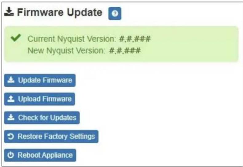
Note: Some buttons only appear on this page when applicable.
Figure 3. Firmware Update Page
To use the Firmware Update page:
1 On the appliance web UI's main page, select Firmware Update to view or update the firmware version.
- If the device is in Standalone mode, the Check for Updates button will be shown. Selecting it checks the Bogen website for the latest firmware version available. If a version newer than the one currently installed is found, it is downloaded to the appliance and the Update Firmware button will be shown.
- If you already have a firmware file you would like to install to the appliance, select Upload Firmware to upload the firmware file from your computer to the appliance. A popup screen appears that allows you to select the file that you want to upload. You can navigate to the file's location. After you select the file, select Upload.
The page displays the uploaded firmware version ("New Nyquist Version") and an Update Firmware button appears. Select this button if you want to update the appliance's firmware to the uploaded version.
- If you want to return your appliance to its original factory configuration, select Restore Factory Settings.
- Select Reboot Appliance to restart your appliance.
Table 3. Firmware Update settings
| Current Nyquist Version Shows the version of the appliance's currently installed firmware. | |
| New Nyquist Version Shows the version of the firmware that has been loaded, though not installed, onto the appliance. | |
| Update Firmware Available only when a new firmware version has been loaded onto the appliance (as specified in New Nyquist Version).Installs the loaded firmware. A reboot may be required after installation. | |
| Upload Firmware Prompts the user to specify a firmware file, which will then be loaded (though not installed) onto the appliance.Note: To obtain the firmware file for a specific version, please contact Bogen Technical Support. | |
| Check for Updates Available only when the appliance is configured for Standalone mode. | |
| Checks the Bogen website for the latest firmware version available and, if it finds a version newer than what is currently installed, downloads it to the appliance.Note: Ensure your Nyquist appliance has network access to bogen-ssu.bogen.com, port 22. | |
| Restore Factory Settings | Returns the appliance to its original factory configuration.Note: This does not install the original appliance firmware. The firmware will not be changed. |
Reboot Appliance Restarts the appliance.
Network Settings Tab Parameters
Network settings can be configured dynamically by the Nyquist server or manually by using the appliance's web UI.
To manually configure network settings:
1 On the appliance web UI's main page, select Network Settings.
2 Select your desired network settings.
3 Select Save.


Figure 4. Network Settings Figure 5. Network Settings (Standalone)
Network settings are described in the following table:
Table 4. Network Settings
IP Address Identifies the IP address assigned to the appliance.
Netmask Identifies the subnetwork subdivision of an IP network.
Gateway Identifies the address, or route, for the default gateway.
Table 4. Network Settings (Continued)
DNS Identifies one or more space-delimited DNS server IP addresses.
Note: If DHCP option 6 (DNS) is provided by a DHCP server, the DHCP-provided DNS configuration and this field will be ignored.
Note: This field is only available when Standalone Operation is enabled.
VLAN ID Identifies the Virtual Local Area Network (VLAN) for this appliance. Values range from 0 to 4094.
VLAN Priority Identifies the priority of the network traffic on the VLAN. Priority can range from 0 through 7.
NTP Server Identifies the IP address or the domain name of the Network Time Protocol (NTP) Server.
Note: This field is only editable when Standalone Operation is enabled.
TFTP Server Identifies the host name or IP address of the Trivial File Transfer Protocol (TFTP) server.
The specified TFTP server can be used to automatically set this device's Configuration settings via the Get Configuration from Server button.
If TFTP Server from DHCP (see below) is set to "Yes", this value will be auto-configured via DHCP option 66, assuming the DHCP server has been configured to provide option 66. For details, see the documentation for your DHCP server.
Note: A TFTP server runs on the Nyquist server on port 69 (the standard TFTP port) and the optional Nyquist DHCP service automatically provides this TFTP address via option 66.
Note: If this value is unspecified, the TFTP Server from DHCP will automatically be set to "Yes", this field will become read-only, and DHCP will be used to configure this setting. To change this value, the TFTP Server from DHCP setting must be set to No, which makes the field editable.
Note: This setting is not available when Standalone Operation is enabled.
Table 4. Network Settings (Continued)
TFTP Server from DHCP "Yes" means the device will use the DHCP option 66 value to retrieve an address for the TFTP Server from DHCP.
"No" means the device will ignore the DHCP option 66 value and use the manually configured value of the TFTP Server (see above).
Note: This setting is not available when Standalone Operation is enabled.
DHCP Enabled Indicates if the device is enabled to use DHCP to retrieve its IP configuration.
Reboot Appliance Indicates that this appliance should reboot when the Save button is clicked.
Configuration Settings Tab Parameters
The easiest way to configure Nyquist appliances is to obtain configuration settings from the Nyquist server by selecting Get Configuration From Server. However, you can manually configure an appliance through the appliance's Web UI when Standalone Operation is enabled (see "Standalone Operation Configuration Settings" on page 11).
To view or manually configure the Nyquist appliance configuration:
1 On the appliance Web UI's main page, select Configuration Settings.
2 View the settings as described in Table 5 on page 10 for normal configuration, or modify the settings as described in "Standalone Operation Configuration Settings" on page 11 for Standalone Operation configuration.
3 If changes were made (Standalone Operation only), click the Save Configuration Settings, Save Multicast Addresses (Transmit/Audiocast), and/or Save Multicast Addresses (Receive) buttons to save your changes.

Figure 6. Appliance Configuration Settings (Standalone disabled)
The following table describes the Configuration Settings tab settings when Standalone Operation is not enabled for this device:
Table 5. Configuration Settings (Standalone disabled)
| Get Configuration from Server | Retrieves configuration settings (i.e., web username, server, and local port) from the TFTP server specified in the Network Settings (see "Network Settings Tab Parameters" on page 6). |
| Web Username Displays the username of the current user. | |
| Emergency-All-Call | Identifies the IP address, port number, cut level (volume), and station list used for emergency all-call pages. |
| All-Call Identifies the IP address, port number, cut level (volume), and station list used for all-call pages. | |
| Audio Distribution | Identifies the IP address, port number, cut level (volume), and station list used for audio distribution. |
Table 5. Configuration Settings (Standalone disabled)
| Multicast # | Identifies the IP address, port number, cut level (volume), and station list used for the multicast audio stream of a specific zone. If this device belongs to more than one zone, then multiple Multicast # entries will be displayed. |
| Nyquist Control Password | Specifies a password used to secure Nyquist control messages between this device and the Nyquist server. This value must match the password specified on the Nyquist server to support certain Nyquist features, such as sound masking, amp protection mode, and station check-in.The specified password must be exactly 20 characters long and include uppercase, lowercase, and numeric characters.Note: This password cannot be set unless the Web Password has been changed from the default value. |
The Configuration Settings tab also displays the following information for each Device Station attached to the device:
Port Number Shows the output port/channel number of the appliance.
Port Type Shows the station type to which the port connects.
Account ID Shows the SIP account (IP address) associated with the device preceded by the extension of the device associated with this port.
Local Port Shows the port used for SIP.
Username Shows the username or extension for the station associated with the port.
Standalone Operation Configuration Settings
Configuring this device consists of specifying one or more of the following:
- The SIP server addresses, ports, and SIP extensions at which to register for incoming SIP calls.
- The output unicast (Transmit/Audiocast) address and port to which the device will send the encoded signal that the device received (and encoded) from the specified line input channel.
- The input unicast (Receive) port number at which the device will receive an encoded signal, which will then be converted to analog and played to the specified output channel(s).
- The output multicast (Transmit/Audiocast) addresses and ports to which the device will send one or two encoded line input signals that the device received (and encoded) from the specified line input channels.
- The input multicast (Receive) addresses and ports at which the device will receive one or more encoded signals, which will then be converted to analog and played to the specified output channels.
To receive networked audio from another GA400P device, configure a Unicast Address (Receive) entry with the unicast port on which to receive the encoded stream. (Note that an IP address need not be specified, as the device's IP address will be used.) Specify a codec, output channel (i.e., Line Output channel), and cut level with which to play the received (and decoded) audio signal. To begin receiving the stream, set the Enabled field to Yes.
To receive networked audio over multicast, configure one or more Multicast Addresses (Receive) entries with the multicast addresses and ports on which to receive the encoded streams. Specify a codec, output channel (i.e., Line Output channel), and cut level with which to play the received (and decoded) audio signal. To begin receiving the stream, set the Enabled field to Yes.
To encode and transmit audio over the network to another device, connect a line-level audio source to one of the Line Input ports. To multicast the signal, configure the Multicast Addresses (Transmit/Audiocast) entry whose channel matches the line input port: specify a codec, cut level, and multicast address and port to which the signal will be streamed. That stream can be consumed by any devices configured to "listen" to the specified multicast traffic (signal). To begin transmitting the stream, set the Enabled field to Yes.
To configure the GA400P device to encode and transmit (unicast) audio over the network to another GA400P device (i.e., send directly to one IP address and port), configure the Unicast Address (Transmit/Audiocast) entry: specify the line input port from which to accept the signal, the codec with which to encode the signal, and the unicast IP address and port to which the encoded signal will be streamed. To begin transmitting the stream, set the Enabled field to Yes.
Important:
If Unicast Port (Receive) and/or Multicast Addresses (Transmit/Audiocast) are enabled, Unicast Address (Transmit/Audiocast) will be disabled and vice versa.

Figure 7. Appliance Configuration Settings (Standalone enabled)
The following table describes the Configuration Settings tab settings when Standalone Operation is enabled for this device:
Table 6. Configuration Settings (Standalone enabled)
Device Type Displays the type of this device.
Device Name Provides a name for this device.
Web Username Specifies a web username for this appliance.
Web Password Specifies a web password for logging into the appliance.
Table 6. Configuration Settings (Standalone enabled)
Web Confirm Password Re-enter the password used to log into the appliance.
Time Zone Specifies the time zone in which the device resides.
Enable SIP Calls Enables this device to receive one-way SIP calls,
wherein only the caller can be heard (such as announcements).
Note: If enabled, other SIP-related configuration settings are displayed.
External Relay Trigger 1/2 Enables/disables the activation of an NO/NC output
relay to notify an external device that an audio signal is being sent to Line Output 1 or 2.
SIP Server Address ^a Specifies the Fully Qualified Domain Name (FQDN) or
IP address of the SIP Registration Server with which the device will register.
SIP Network Port ^a Specifies the IP port on which to communicate with the
SIP Registration Server (typically 5060).
SIP Codecs ^a Displays a read-only list of codecs allowed on SIP ses-
sions.
SIP Extension ^a
Specifies the SIP extension for Line Output 1 or 2.
(Line Output 1/2) The extension, along with the IP address, is used to
specify the URI used to place a SIP call to this extension:
sip:
SIP Username ^a
Specifies the SIP username used to register Line Output 1 or 2 with the SIP server.
(Line Output 1/2)
Specifies the SIP registration password used to register
SIP Password ^a
Line Output 1 or 2 with the SIP server.
(Line Output 1/2)
Specifies the intercom cut volume to be used for SIP calls over Line Output 1 or 2.
Cut Level ^a
This can be a value from -42 and 0 dB.
(Line Output 1/2)
The default value is -20 dB.
Note: To modify, click on the value, adjust the slider on the popup
using the cursor keys or mouse, and click the check box button.
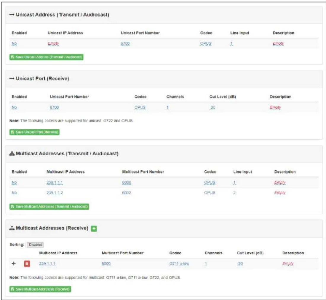
Figure 8. Unicast/Multicast Configuration Settings (Standalone enabled)
The following parameters appear for the Unicast Address (Transmit/Audiocast) (i.e., outgoing unicast stream), Unicast Port (Receive) (i.e., incoming unicast stream), Multicast Addresses (Transmit / Audiocast) (i.e., outgoing multicast streams) and for each of the Multicast Addresses (Receive) (i.e., incoming multicast streams) configured for this device.
Enabled Enables sending (Transmit/Audiocast) audio signals from
| the Line Input ports to the specified unicast or multicast addresses and ports and/or receiving an incoming stream (Receive) from a unicast address and output it to one or more output channels. | |
| Unicast IP Address(Unicast only) | Specifies the unicast IP address an which to send audio streams. |
| Unicast Port Number(Unicast only) | Specifies the unicast port number on which to send or receive audio streams. |
| Multicast IP Address(Multicast only) | Specifies the multicast IP address on which to send or receive audio streams. |
| Multicast Port Number(Multicast only) | Specifies the multicast port on which to send or receive audio streams. |
Codec Specifies the codec to be used when encoding or decoding audio. Select one of the following values:
• G711 u-law (multicast receive only)
- Intercom call quality
- A narrowband audio codec that provides toll-quality audio at 64 kbps. The u-law version is primarily used in North America and Japan.
• G711 a-law (multicast receive only)
- Intercom call quality
- A narrowband audio codec that provides toll-quality audio at 64 kbps. The a-law version is primarily used in most countries outside of North America and Japan.
• G722
- Tone and paging quality
- A wideband audio codec operating at 48, 56, and 64 kbps.
• OPUS
- Music quality
- An audio codec format designed for speech and general audio, supporting low latency, constant and variable bitrate encoding (6 to 510 kbps), and five sampling rates (from 8 to 48 kHz).
Line Input
(Transmit/Audiocast only)
The line input(s) from which to source the multicast or unicast stream.
Channel 1 or 2 can be specified.
Channels
(Receive only)
Channel(s) on which the received unicast or multicast audio streams will be output.
Channel 1 and/or 2 can be specified.
Tip: If multiple output channels are selected, they will all use the same cut level. Fine tuning of cut levels per output channel can be adjusted using DSP settings.
Cut Level (dB)
(Receive only)
Specifies the cut level for the received unicast or multicast audio stream.
This can be a value from -70 to 0 dB.
The default value is -20 dB.
Note: To modify, click on the value, adjust the slider on the popup using the cursor keys or mouse, and click the check box button.
Tip: If multiple output channels are selected, they will all use the same cut level. Fine tuning of cut levels per output channel can be adjusted using DSP settings.
Description User-specified description of this unicast or multicast address.
This setting can contain a maximum of 30 characters and should not contain any of the following:
[ ] { } < > , | :
Note: A maximum of 24 received multicast audio streams are supported.
Note: Multicast Addresses should be ordered by priority, highest priority first. If multiple streams are active on the same channel simultaneously, the one with the highest priority will be played. Set the Sorting switch to Enabled and drag entries up and down using the 4-way-arrow symbols to rearrange the priorities.
Accessing Log Files
A log file records events and messages that occur when software runs, to be used when troubleshooting the appliance. From the appliance's web-based UI, log files can be viewed directly or exported via download to your PC, Mac, or Android device, where they can be copied to removable media or attached to an email for technical support.
To view a log file:
1 On the appliance Web UI's main page, select Logs.
2 From the drop-down menu, select the log that you want to view.
Multiple versions of the same log, and zipped copies of the log, may be available.
3 To export the file, select Export.
A link to a .txt file appears in the browser's lower left corner.
![Logs syslog /var/log/syslog Export Sep 26 14:53:10 arm rsyslogd: [origin software="rsyslogd" swVersion="8.4.2" x-pid="653" x-info="http://www.rsyslog.com"] rsyslogd was HUPed Sep 26 14:53:10 arm rsyslogd:0: action 'action 17' resumed (module 'builtin:ompipe') [try http://www.rsyslog.com/e/0] Sep 26 14:53:10 arm rsyslogd-2359: action 'action 17' resumed (module 'builtin:ompipe') [try http://www.rsyslog.com/e/2359] Sep 26 14:53:25 arm nyq-appliance[1881]. Server: Asterisk PBX 13.11.2 Sep 26 14:53:25 arm nyq-appliance[1881]. Content-Length: 0 Sep 26 14:53:25 arm nyq-appliance[1881] #015 Sep 26 14:53:25 arm nyq-appliance[1881] --end msg-- Sep 26 14:53:25 arm nyq-appliance[1881] 14:52:31.026 pjsua_core.c ....TX 764 bytes Request msg REGISTER/cseq=21859 (tdta0xb57039f0) to UDP 10.10.10.31:5060. Sep 26 14:53:25 arm nyq-appliance[1881]. REGISTER sip:10.10.10.31 SIP/2.0 Sep 26 14:53:25 arm nyq-appliance[1881]. Via: SIP/2.0/UDP 10.10.10.35:47339;rport:branch=z9hG4bKPjg3eYVWsb1aQhd-E7VOgOhDSOk3W9Br6 Sep 26 14:53:25 arm nyq-appliance[1881]. Max-Forwards: 70 Sep 26 14:53:25 arm nyq-appliance[1881]. From: ;tag=8bPAJToVgud3lIuoLNwPOnCP1gLEGYh1 Sep 26 14:53:25 arm nyq-appliance[1881]. To: Sep 26 14:53:25 arm nyq-appliance[1881]. Call-ID: 66YgYg4rokpnn/JOxgjuYaW1m0pGPwr1 Sep 26 14:53:25 arm nyq-appliance[1881]. CSeq: 21859 REGISTER Sep 26 14:53:25 arm nyq-appliance[1881]. Contact: Sep 26 14:53:25 arm nyq-appliance[1881]. Expires: 60 Sep 26 14:53:25 arm nyq-appliance[1881]. Allow: PRACK, INVITE, ACK, BYE, CANCEL, UPDATE, INFO, SUBSCRIBE, NOTIFY, REFER, MESSAGE, OPTIONS Sep 26 14:53:25 arm nyq-appliance[1881]. Authorization: Digest username="0107", realm="asterisk", nonce="1506437551/7ac1109379c6794efd698903la7a5603", uri="sip:10.10. Sep 26 14:53:25 arm nyq-appliance[1881]. Content-Length: 0 Sep 26 14:53:25 arm nyq-appliance[1881]. #015 Sep 26 14:53:25 arm nyq-appliance[1881] --end msg-- Sep 26 14:53:25 arm nyq-appliance[1881] 14:52:31.035 pjsua_core.c .RX 495 bytes Response msg 200/REGISTER/cseq=21859 (rdata0xb57012ac) from UDP 10.10.10.31:506 Sep 26 14:53:25 arm nyq-appliance[1881]. SIP/2.0 200 OK Sep 26 14:53:25 arm nyq-appliance[1881]. Via: SIP/2.0/UDP 10.10.10.35:47339;rport=47339;received=10.10.10.35;branch=z9hG4bKPjg3eYVWsb1aQhd-E7VOgOhDSOk3W9Br6 Sep 26 14:53:25 arm nyq-appliance[1881]. Call-ID: 66YgYg4rokpnn/JOxgjuYaW1m0pGPwr1 Sep 26 14:53:25 arm nyq-appliance[1881]. From: ;tag=8bPAJToVgud3lIuoLNwPOnCP1gLEGYh1 Sep 26 14:53:25 arm nyq-appliance[1881]. To: ;tag=z9hG4bKPjg3eYVWsbiaQhd-E7VOgOhDSOk3W9Br6](/content/2026/05/984605/images/0409417da07388627f8b2c2aec70c560767f6617d56e2bd01498efc050767b43.jpg)
Figure 9. Logs
Available logs are described in the following table. If a log file is empty, however, it will not appear in the drop-down list of available logs.
Table 7. Logs
| Log Description | |
| ampws.log Contains information | about protection status and logs protection events with temperature information at the time of event. |
| auth.log Contains system authorization | information, including user logins and authentication methods that were used. |
| btmp Contains information about failed login attempts. | |
| daemon.log Contains information logged by the various back-ground daemons that run on the system. | |
| debug Contains errors and debug information. | |
| dpkg.log Contains information | that is logged when a package is installed or removed using dpkg command. |
| faillog Contains user failed login attempts. | |
| kern.log Contains information | logged by the kernel and recent login information for all users. |
| lastlog Contains information on the last login of each user. | |
| messages Contains messages generated by Nyquist. | |
| php5-fpm.log Contains errors | generated by the PHP script. |
| syslog Contains list of errors that occur when the server is running and server start and stop records | |
| user.log Contains information about all user level logs. | |
Setting DSP Parameters
When you select DSP (Digital Signal Processing) from the appliance's web UI, the DSP page appears. This page presents a mixing board interface, allowing you to monitor, control, and perform DSP operations on the signals of the input and output channels.
Note: Digital Signal Processing (DSP) refers to the digital operations that are performed to modify or control the digital signal.

Figure 10. DSP Page
Note: The terms analog input and analog output will be used to refer to the electrical signals on the physical analog ports (e.g., from a microphone and to an amplifier) while network send and network receive will refer to the digital streams that are sent and received over the network.
The DSP page displays a mixing board console containing two input strips and two output strips. The input strips accept the analog inputs from the line input connectors and—after gain adjustments, analog-to-digital conversion, and DSP enhancements—send the digital network send over the network. The output strips accept the digital net-
work receive from the network and—after DSP enhancements, digital-to-analog conversion, and gain adjustments—send the analog output to the line output connectors.
Each strip controls the audio signal for a given channel, providing muting, gain adjustments, signal processing, and more. Signal processing includes traditional audio processing, such as hi/low-pass filters (output), limiters (input), and parametric EQs (output).
This console can be used to do the following:
• View Signal indicators for each channel.
- Adjust the Input Gain level for each analog input signal.
- Adjust the Input 1/2 level for each network send signal.
- Adjust the Output 1/2 level for each analog output signal.
- Apply DSP effects to the digital signals of both the input and output channels.
Selecting the DSP Features menu at the top-right corner of a channel displays a menu of DSP features for that channel. Each channel, both input and output, has its own associated menu, and the corresponding DSP features will be applied to the signal for that particular channel.
The various mixer controls, as well as the DSP features available via the DSP Features menu, are briefly described in the following table and will be discussed in more detail in subsequent sections.
Note: The DSP page (including the mixing board and other DSP pages) can only be used by one browser session at a time. If another session is already connected and using this DSP page, the mixing board displayed will be disabled.
Table 8. DSP Page
Save Settings to Server Backs up the DSP settings to the server. If this device is later replaced or reset to factory defaults, these DSP settings can be restored when the new device is "swapped" for the old on the Nyquist server.
Note: This button appears on each DSP feature page.
Mute Silences the audio for the selected channel.
DSP Features button Presents a menu of DSP features that can be applied to the corresponding channel.
Channel Fader Adjusts the channel volume level in 1 dB increments.
Signal LED Illuminates when a signal is present.
Table 8. DSP Page
IN VU meter Indicates the strength of the analog input signal.
OUT VU meter Indicates the strength of the network send signal.
Input Gain
Adjusts the strength of the analog input signal.
The DSP features that can be applied to a channel, accessible through the DSP Features menu, are described in the following table.
Table 9. DSP Features
| High/Low Pass (Output only) | Filters out frequencies in the input signal that are above and below specified high and low cutoff frequencies. |
| Limiter (Input only) | Prevents a signal from exceeding a certain preset maximum level. |
| Parametric EQ (Output only) | Uses a center/primary frequency to all tailoring of the frequency content of an audio signal. |
Settings Allows you to provide names and colors for the input and output channels.
Signal Present Allows you to configure the threshold level and duration that a signal must reach before the Signal LED will be activated for this channel.
Reset button Present on almost all DSP screens other than the main mixer, this button will reset the DSP settings to the displayed feature's default setting.
Setting the Channel Level
The channel level control is a channel fader, which is adjusted in 1-dB increments and controls the output level for the channel. The channel levels can range from -60 to +12 dB. If you place the mouse over the fader, the numerical value of the level appears.
Adjusting Volume Levels
The channel fader control can be used to adjust the channel's output level in 1-dB increments between -60 and +12 dB. The overall adjusted output level of the channel signal can be viewed on the OUT VU meter, marked in 2-dB increments between -60 and 0 dB.
Tip: For best results, adjust input signal levels until you have a strong signal (i.e., within the green and yellow areas on the meter), then adjust the final output levels using the DSP Outputs controls.
To adjust the channel volume level:
1 On the appliance Web UI's main page, select DSP.
2 Use the channel's fader to adjust the volume level.
Knob Adjustments
Many DSP controls use knobs to adjust one or more settings. The value of a knob can be adjusted in one of two ways:
1 Click the knob control, hold the mouse button down, and drag the mouse up or down to increase or decrease the value.
2 Double-click the knob, type a value into the resulting popup, and click the Save button.
Signal Indicators
Each input channel has signal indicators and two vertical volume unit (VU) meters, labeled "IN" and "OUT".
The green input signal LED(s) automatically illuminates when a signal is being received.
The "IN" VU meter indicates the strength of the channel's input signal (after gain adjustments), while the "OUT" VU meter indicates the strength of the channel's output signal. The VU meter not only illuminates green, yellow, or red (depending on the signal level), but also has a scale ranging from -60 to 0 dB to indicate the actual signal level.
Muting a Channel
You can mute a channel to cut off an audio signal and stop the input signal from being sent to the output channel. Note the input signal will still be visible on the IN meter, but the OUT meter will show that nothing is being forwarded to the output channel.
To mute a channel:
1 On the appliance Web UI's main page, select DSP.
2 Click the Mute button for the channel that you want to silence.
The Mute button will illuminate red. You can click the Mute button again to unmute the channel.
Adjusting Input Gain
Because input signal levels can vary greatly based on the attached device, you will want to adjust the Input Gain for a channel to ensure the input signal level is high enough to use, but not so high that it sounds distorted. The input signal level can be viewed on the "IN" VU meter and adjusted using the Input Gain knob.
Tip: Typically, a good input signal will vary between the high green and low yellow areas of the VU meter, but your ears should be the ultimate judge of a good signal. Remember, the purpose of the Input Gain is to adjust the strength of the input signal, not the volume of the final output signal.
Troubleshooting Gain Structure
Channel faders should be set to 0 dB (unity gain) during the channel-level setup procedure.
The optimal operational range of the Input Gain control knob is from about 9 o'clock to 2 o'clock.
If Channel Clipping Occurs
If the signal is clipping or producing audible distortion, the gain is too high. Reduce the Input Gain knob by turning the knob counterclockwise until the clipping and distortion have been eliminated.
Also, make sure that the Input Gain is set within the optimal range between the 0 and -20 dB positions on the gain control knob.
If Channel Volume Is Too Low
If the channel fader volume control must be set above the +6 dB position to provide adequate volume, the Input Gain setting is too low. Set the channel level fader to 0, turn the Input Gain knob to the 1 o'clock position, and increase the Input Gain by turning the knob clockwise until clipping occurs or the VU meter's signal level is between -10 dB and -3 dB. Then, adjust the Input Gain to a setting just below the clipping level.
If Channel Volume Is Too High
If a channel is not clipping but the channel fader level control must be set below the -20 dB position to achieve the proper volume level, the Input Gain control setting is too high. Set the channel fader to the 0 dB position and adjust the Input Gain control knob until the desired volume level is achieved. Reduce the Input Gain by turning the knob counterclockwise.
High/Low Pass
High-pass filters allow signals that are higher than the specified frequency and attenuate signals that are lower. Low-pass filters allow signals that are lower than the specified frequency and attenuate signals that are higher. When combined, they are known as a band-pass filter.
You can specify the range of frequencies that will pass through the high-pass and low-pass filters and select the type of filter that is used through the channel's High/Low Pass drop-down menu option.

Figure 11. High/Low Pass Parameters
To adjust the high/low pass parameters for a channel:
1 On the appliance Web UI's main page, select DSP.
2 Select the Menu button for the channel.
3 From the drop-down menu, select High/Low Pass.
Note: If you want to return to the factory settings, select the Reset icon that appears in the right corner.
4 Set the parameters described in the following table:
Table 10. High/Low Pass Parameters
High-Pass (Low Cut)
This feature helps eliminate low-frequency noise (signals of 100 Hz and below, such as background rumble from ventilation systems, etc.).
Enable Enables or disables the High-Pass filter.
Frequency Set the cutoff frequency. You can adjust the frequency by
moving the knob (click and move up or down) or by double-clicking the knob and typing the frequency. When typing the frequency, only numeric values from 20 Hz to 20,000 Hz can be entered.
The high-pass filter attenuates content below this frequency and lets frequencies above this cutoff frequency pass through the filter.
Type Available filter types are:
- Linkwitz-Riley (12, 24, 36, and 48 dB per octave)
- Butterworth (6, 12, 18, 24, 30, 36, 42, and 48 dB per octave)
• Bessel (12, 18, and 24 dB per octave)
Note: The term "dB per octave" describes how steeply frequencies below the selected cutoff frequency are attenuated. For example, if the cutoff frequency is 100 Hz and the filter type specifies 12 dB per octave, a 50-Hz signal (i.e., one octave lower) will be attenuated by 12 dB and a 25-Hz signal (i.e., two octaves lower) will be attenuated by an additional 12 dB.
Low-Pass (High Cut)
This feature helps eliminate high-frequency noise (signals of 8000 Hz and above) such as background hiss and sibilance (excessive "S" in vocals, etc.).
Enable Enables or disables the Low-Pass filter.
Table 10. High/Low Pass Parameters (Continued)
Frequency Set the cutoff frequency. You can adjust the frequencies by
moving the knob (click and move up or down) or by double-clicking the knob and typing the frequency. When typing the frequency, only numeric values from 20 Hz to 20,000 Hz can be entered.
The low-pass filter attenuates content above this frequency and lets frequencies below this cutoff frequency pass through the filter.
Type Available filter types are:
- Linkwitz-Riley (12, 24, 36, and 48 dB per octave)
- Butterworth (6, 12, 18, 24, 30, 36, 42, and 48 dB per octave)
• Bessel (12, 18, and 24 dB per octave)
Note: The term "dB per octave" describes how steeply frequencies above the selected cutoff frequency are attenuated. For example, if the cutoff frequency is 8,000 Hz and the filter type specifies 12 dB per octave, a 16,000-Hz signal (i.e., one octave higher) will be attenuated by 12 dB and a 32,000-Hz signal (i.e., two octaves higher) will be attenuated by an additional 12 dB.
Limiter
A limiter is a compressor with a high slope (i.e., attack) that is used to prevent a signal from exceeding a set decibel level. Limiters are used as safeguards against signal clipping.
Limiter parameters are set per channel.
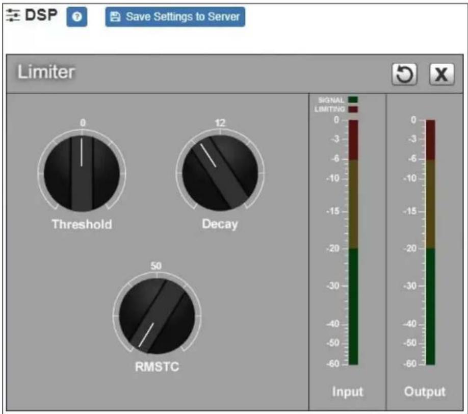
Figure 12. Limiter Settings
To adjust the limiter settings for a channel:
1 On the appliance Web UI's main page, select DSP.
2 Select the Menu button for the channel or select the Menu button for the Output.
3 From the drop-down menu, select Limiter.
Note: If you want to return to the factory settings, select the Reset icon that appears in the right corner.
4 Adjust the following settings as needed:
Table 11. Limiter Settings
Threshold Sets the signal level at which the limiter is triggered. Any signal exceeding this threshold will be compressed to this level.
The range is -24 to +24 dB.
Decay Sets the rate for turn off of the limiter after the signal is below the threshold.
Decay range is 5 to 2300 milliseconds.
RMSTC Sets how fast the limiter reacts to a signal that has exceeded the threshold.
(Root Mean Square Time Constant) RMSTC range is 50 to 10000 dB/sec.
Parametric EQ
A parametric equalizer is a multi-band variable equalizer that allows control of frequency amplitude (boost/cut), center frequency, and frequency bandwidth, or Q.

Figure 13. Parametric Equalizer Settings
The parametric equalizer settings for your device allows you to adjust the Q and gain for five separate frequencies, which then become plot points on the screen's graph.
To adjust the parametric equalizer settings for a channel:
1 On the appliance Web UI's main page, select DSP.
2 Select the Menu button for the channel.
3 From the drop-down menu, select Parametric EQ.
Note: If you want to return to the factory settings, select the Reset icon that appears in the right corner.
4 Adjust frequencies as desired, ensuring the Enable LEDs are green for each selected frequency. You can adjust the frequencies by moving the Freq knob or by double-clicking the knob and typing the frequency. When typing the frequency, only numeric values from 20 to 20,000 can be entered.
5 Make desired Q adjustments by adjusting knob (or double-clicking and typing the desired adjustment). Q can be from 0.1 to 20 and sets how wide to either side of the selected frequency the adjacent frequencies are affected.
Q is the Quality or Quality Factor, which refers to the bandwidth of one band of a parametric equalizer. Q is calculated by dividing the center frequency in Hz by the width of the boost or cut zone, +3 dB or -3 dB above or below 0 dB.
6 For each frequency, use the Gain knob or double-click the knob and type the gain to either boost (turn up) or cut (turn down).
Gain knobs can be moved between +12 or -12 dB. By default, each knob is set at 0 dB, which means that no frequencies are being boosted or cut.
7 Select Save Settings to Server.
Settings
You can specify custom names and colors for each of the input and output channels. This allows you to customize the appearance of the mixer board.

Figure 14. Settings Parameters
To adjust the settings for a channel:
1 On the appliance Web UI's main page, select DSP.
2 Select the Menu button for the channel.
3 From the drop-down menu, select Settings.
Note: If you want to return to the factory settings, select the Reset icon that appears in the right corner.
4 For each channel, type the name that you want to display for the channel.
5 For each channel, select a color that will be used to highlight the channel.
6 Select Save.
Signal Present
You can configure the threshold level that a signal must reach before the signal LED is lit, as well as how long the LED will remain lit. You can configure this for each channel.

Figure 15. Signal Present Parameters
To adjust the Signal Present settings for a channel:
1 On the appliance Web UI's main page, select DSP.
2 Select the Menu button for the channel.
3 From the drop-down menu, select Signal Present.
Note: If you want to return to the factory settings, select the Reset icon that appears in the right corner.
4 Adjust the following settings as needed.
Table 12. Signal Present Parameters
Threshold Sets the minimum level the signal must reach before the signal LED is illuminated.
Threshold range is -144 to +24 dB.
Hold Sets the minimum number of milliseconds that the signal LED will remain illuminated.
Hold range is 2 to 200 milliseconds.
Appendix A: Bogen Digital Certification Authority
Installing the Bogen Digital Certification Authority
When your client (e.g., a web browser) connects to the Bogen device's web application, the device's digital certificate is sent to the client to authenticate the identity of the device's web application. The client uses the Bogen Certification Authority (CA) certificate to authenticate the device's digital certificate, which verifies that the client is connecting to a valid server. If you do not install the Bogen CA certificate, the browser will display a warning that it was unable to authenticate the server, displaying a red Not secure warning immediately to the left of the browser's address bar when you attempt to access the Bogen device.
Installing Certification Authority on Windows System
To download and install the Certification Authority on a Windows device:
1 From your Chrome or Edge browser, type http://
2 Select the downloaded file and select Open.
3 Select Open when prompted with "Do you want to open this file?"
4 Select the Install Certificate... button. The Certificate Import Wizard starts.
5 Select Current User, and then select Next.
Note: To allow all users on this Windows client to access the Nyquist device, select Local Machine instead of Current User. You may be prompted for administrator credentials.
6 Select "Place all certificates in the following store", then select Browse.
7 Select Trusted Root Certification Authorities, and then select OK.
8 Select Next.
9 Select Finish.
10 Restart the browser and log in to the device's web application.
You can also download and install the Certification Authority using a PowerShell command prompt or script, which involves fewer steps.
To download the certificate to a CRT file, execute the following PowerShell command, replacing
Invoke-WebRequest -Uri http://<device>/ssl/bogenCA.crt -OutFile $env:TEMP\bogenCA.crt
If you wish to validate the certificate before importing it, execute the following command after retrieving the CRT file:
(New-Object -TypeName Security.Cryptography.X509Certificates.X509Certificate2 -ArgumentList "$env:temp\bogenCA.crt").GetCertHashString()
The output will be the hash value (i.e., thumbprint) of the downloaded certificate, which should match the following (as of the current release):
0A8248F69D970F8DD855D0E0592972DA64B1A845
To install the certificate for the current user, execute the following command:
Import-Certificate -CertStoreLocation cert:\CurrentUser\Root -FilePath $env:TEMP\bogenCA.crt
That command installs the CA certificate into the CurrentUser certificate store, which only applies to the current user. To install the certificate for all users on this machine, which requires administrator privileges to execute, execute the following command:
Import-Certificate -CertStoreLocation cert:\LocalMachine\Root -FilePath $env:TEMP\bogenCA.crt
Note: These commands can also be executed remotely using PowerShell Remoting, which may be helpful if the certificate needs to be installed on many client machines.
Installing Certification Authority on Mac System
To download and install the Certification Authority on a Mac:
1 From your Chrome or Edge browser, type http://
2 Save the downloaded bogenCA.crt file to the desktop.
3 Double-click the certificate file on the desktop. The Keychain Access App opens.
4 Double-click the certificate to reveal the trust settings.
5 Change the top trust setting to Always Trust.
6 Close the Trust Setting window and enter the computer administrative password to save.
7 Restart the browser and log in to the Nyquist web application.
Note: The Android device WiFi must be connected to the same network as the Nyquist Server.
To download and install the Certification Authority on an Android device:
1 From your Chrome or Edge browser, type http://
2 If prompted, verify your identity (e.g., enter your PIN or fingerprint).
3 Type a certificate name (e.g., "Bogen CA"), specify "VPN and apps" under "Used for", and select OK to install the certificate.
Installing Certification Authority on an iOS Device
Note: The iOS device WiFi must be connected to the same network as the Nyquist Server.
To download and install the Certification Authority on an iPhone Operating System (iOS) device:
1 From your Safari browser, type http://
2 Select Go.
3 Select Allow when prompted to allow the download.
4 Select Close after the notification that a profile was downloaded.
5 Select Settings > General > VPN & Device Management.
6 Select the Bogen CA certificate under DOWNLOADED PROFILE.
7 Select Install.
8 If prompted, enter your passcode.
9 On the Warning page, select Install.
10 Select Done.
11 Select Settings > General > About > Certificate Trust Settings.
12 Under ENABLE FULL TRUST FOR ROOT CERTIFICATES, Enable the switch next to Bogen CA.
Viewing the Certificate
The following steps outline how to view and verify the TLS/SSL certificate that was provided by the Nyquist device.
Important: The user interfaces for browsers change not infrequently, so the exact details may vary from what is described in the following instructions. Some security packages can also affect the information available, such as antivirus software that injects its own CA certificate in lieu of the website's actual certificate, which has the effect of hiding the actual certificate from the user.
1 Browse to the Bogen device's web application in your browser (using Safari on iOS, Chrome or Edge on all other platforms).
2 Select the lock icon on the address bar of the browser (to the left of the URL).
3 Display the CA certificate by following one of the following steps:
a) On the Chrome or Edge browser, select Connection is secure, then select either Certificate is valid, the certificate icon, or Certificate information to display the Certificate Viewer dialog. Select the Details tab, then Bogen CA in the Certificate Hierarchy section.
b) On the Safari browser [MacOS or iOS only], select Show Certificate in the window that appears.
c) As an alternative on Android devices, select the Android system's Settings > Biometrics and security > Other security settings > View security certificates, select the USER tab, and select the Bogen certificate.
4 Verify that the Bogen CA certificate is selected and not the server certificate (the server certificate's name will be an IP address). To verify that the certificate is valid, verify that the displayed fingerprint values match the following:
SHA-1: 0A 82 48 F6 9D 97 0F 8D D8 55 D0 E0 59 29 72 DA 64 B1 A8 45
SHA-256: 6B D0 D5 8D C8 F7 E8 03 9E A3 F1 52 32 1D 9C 5C 58 8B 4E FA DF 03 43 64 34 C2 6C 63 C5 4A AC 46
- 2-Channel AoIP Gateway Configuration Guide
- Contents
- Configuring the Nyquist AoIP Gateway 1
- Appendix A: Bogen Digital Certification Authority 35
- Configuring the Nyquist AoIP Gateway
- Using the Dashboard
- Table 1. Appliance Dashboard Fields
- Table 2. Appliance Dashboard Buttons
- Standalone Operation
- Updating Firmware
- Network Settings Tab Parameters
- Table 4. Network Settings
- Table 4. Network Settings (Continued)
- Configuration Settings Tab Parameters
- Standalone Operation Configuration Settings
- Table 6. Configuration Settings (Standalone enabled)
- Line Input
- Channels
- Cut Level (dB)
- Description User-specified description of this unicast or multicast address.
- Accessing Log Files
- Setting DSP Parameters
- Table 8. DSP Page
- Setting the Channel Level
- Adjusting Volume Levels
- Knob Adjustments
- Signal Indicators
- Muting a Channel
- Adjusting Input Gain
- Troubleshooting Gain Structure
- If Channel Clipping Occurs
- If Channel Volume Is Too Low
- If Channel Volume Is Too High
- High/Low Pass
- Table 10. High/Low Pass Parameters
- High-Pass (Low Cut)
- Low-Pass (High Cut)
- Table 10. High/Low Pass Parameters (Continued)
- Limiter
- Table 11. Limiter Settings
- Parametric EQ
- Settings
- Signal Present
- Table 12. Signal Present Parameters
- Appendix A: Bogen Digital Certification Authority
- Installing the Bogen Digital Certification Authority
- Installing Certification Authority on Windows System
- Installing Certification Authority on Mac System
- Installing Certification Authority on an iOS Device
- Viewing the Certificate
Brand : Bogen
Model : Nyquist NQ-GA400P
Category : Processor