CM4-750 - Receiver AudioControl - Free user manual and instructions
Find the device manual for free CM4-750 AudioControl in PDF.


| Product Type | Multi-Channel Receiver |
| Brand | AudioControl |
| Model | CM4-750 |
| Number of Channels | 4 (750 watts per channel) |
| Dimensions (H x W x D) | 3.5 x 17.25 x 12 inches |
| Weight | 20 lbs |
| Power Supply | 120V AC, 60 Hz |
| Power Consumption | 1500W max |
| Frequency Response | 20 Hz - 20 kHz ±0.5 dB |
| Inputs | 4 pairs RCA line inputs |
| Outputs | 4 pairs speaker outputs (binding posts) |
| Trigger Input | 12V DC trigger |
| Cooling | Convection cooled with heat sinks |
| Protection Circuits | Short circuit, overheat, DC offset |
| Maintenance | Wipe with dry soft cloth; do not use solvents |
| Safety | Do not expose to rain or moisture; disconnect power before cleaning |
| Spare Parts | Contact authorized AudioControl service center |
| Repairability | Repairs should be performed by qualified personnel |
| General Information | High-performance receiver for home or commercial audio systems |
Frequently Asked Questions - CM4-750 AudioControl
User questions about CM4-750 AudioControl
0 question about this device. Answer the ones you know or ask your own.
Ask a new question about this device
Download the instructions for your Receiver in PDF format for free! Find your manual CM4-750 - AudioControl and take your electronic device back in hand. On this page are published all the documents necessary for the use of your device. CM4-750 by AudioControl.
USER MANUAL CM4-750 AudioControl
CM Series Amplifiers CM2-750, CM3-750, CM4-750
2, 3, 4 CHANNEL, LOW IMPEDANCE / 70V / 100V
POWER AMPLIFIERS
OPTIONAL DANTE PORT
FOR RESIDENTIAL AND COMMERCIAL APPLICATIONS
Important Safety Instructions
- Read these instructions.
- Keep these instructions.
- Heed all warnings.
- Follow all instructions.
- Do not use this apparatus near water.
- Clean only with a dry cloth.
- Do not block any ventilation openings. Install in accordance with the manufacturer's instructions.
- Do not install near any heat sources such as radiators, heat registers, stoves, or other apparatus (including amplifiers) that produce heat.
- Protect the power cord from being walked on or pinched particularly at plugs, convenience receptacles, and the point where they exit from the apparatus.
- Only use attachments/accessories specified by the manufacturer.
- Unplug this apparatus during lightning storms or when unused for long periods of time.
- Refer all servicing to qualified service personnel. Servicing is required when the apparatus has been damaged in any way, such as power-supply cord or plug is damaged, liquid has been spilled or objects have fallen into the apparatus, the apparatus has been exposed to rain or moisture, does not operate normally, or has been dropped.
- This apparatus shall not be exposed to dripping or splashing, and no object filled with liquids, such as vases or glasses, shall be placed on the apparatus.

The lightning flash with arrowhead symbol within an equilateral triangle is intended to alert the user to the presence of uninsulated "dangerous voltage" within the product's enclosure, that may be of sufficient magnitude to constitute a risk of electric shock to persons.

The exclamation point within an equilateral triangle is intended to alert the user of the presence of important operating and maintenance (servicing) instructions in the literature accompanying the appliance.
AudioControl®
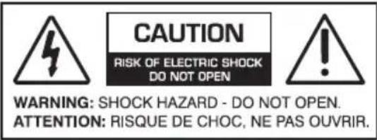
Caution: to reduce the risk of electric shock, do not remove the top cover. There are no user-serviceable parts inside. Refer servicing to qualified personnel.
This equipment has been tested and found to comply with the limits for a Class B digital device, pursuant to part 15 of the FCC Rules.
These limits are designed to provide reasonable protection against harmful interference in a residential installation.
This equipment generates, uses, and can radiate radio frequency energy and, if not installed and used in accordance with the instructions, may cause harmful interference to radio communications. However, there is no guarantee that interference will not occur in a particular installation.
If this equipment does cause harmful interference to radio or television reception, which can be determined by turning the equipment off and on, the user is encouraged to try to correct the interference by one or more of the following measures:
- Reorient or relocate the receiving antenna.
- Increase the separation between the equipment and the receiver.
- Connect the equipment into an outlet on a circuit different from that to which the receiver is connected.
- Consult the dealer or an experienced radio/TV technician for help.
CAUTION: Changes or modifications to this device not expressly approved by AudioControl Inc. could void the user's authority to operate the equipment under FCC rules.
Recycling notice: If the time comes and this apparatus has fulfilled its destiny, do not throw it out into the trash. It has to be carefully recycled for the good of mankind, by a facility specially equipped for the safe recycling of electronic apparatii. Please contact your local or state recycling leaders for assistance in locating a suitable nearby recycling facility. Or, contact us and we might be able to repair it for you.
Table of Contents
Important Safety Instructions ..... 2
Table of Contents 3
Introduction....4
Features 4
Complimentary Features 6
Quick View....7
Front Panel 7
Rear Panel 7
Getting Started 8
Installation Examples....8
Front Panel Features.....13
Rear Panel Features 15
Speaker and Wiring Impedance ..... 18
12 Volt Trigger Ins and Outs ..... 19
Ventilation 21
Internet Connectivity and Control...22
Acoustics 36
Equalization.... 37
Advanced Discussions....40
Troubleshooting 42
Block Diagram.... 44
Specifications 45
Service 46
The Warranty....47
The Crossover Two-Step....52
| Network Settings | |
| Default IP Address | 192.168.0.249 |
Introduction
Congratulations!
If you are reading this user's manual then it is likely that you are involved in the installation of an AudioControl CM Series amplifier. This amplification product was designed to allow the user to maximize the performance of any distributed audio speaker system, whether you are using traditional low impedance (LoZ) or 70/100 volt (HiZ) speaker systems...or both.
The AudioControl CM Series amplifiers were designed to optimize the performance of today's residential and commercial architectural speakers systems, including in-wall, in-ceiling, pendants, invisible, plus high performance outdoor audio systems. Great sound in your backyard and elsewhere is amazing!
The CM Series amplifiers are unique in the realm of 70-volt options because they offer DSP control and signal matrixing capabilities developed by AudioControl for their award-winning Director Series amplifiers. Features like ethernet control, analog and digital inputs, full DSP capabilities including graphic and parametric equalization, crossover filters, speaker profiles plus audio matrixing, make these a truly special family of amplifiers.
AudioControl's engineers have matched these unique features around an amplifier platform that is designed to maximize power output levels, with minimal heat dissipation, making the CM Series "one cool customer" which is critical in the rack design of many systems.
AudioControl has long been known for “Making Good Sound Great,” so maximum audio performance was a key design element for the CM Series. While some companies consider whole house audio just for background sound, our approach is to deliver an amazing audio performance of music throughout the entire system.
The CM Series amplifiers are designed and manufactured in the USA by AudioControl, the only electronics company in the world that specializes in amplifiers, equalizers, signal processors and audio analyzers. Our passion for high quality, meticulous attention to detail, and pro sound heritage shows itself in the dozens of awards we have won for our designs, products, and service over the past four decades.
This is a professional installer's manual and covers all members of AudioControl's CM Series family, and is designed to assist in getting the optimum performance out of this unique product. The CM Series models are similar in operation, aside from the number of inputs, outputs and channel counts, and this manual covers all models. We assume this product is being professionally installed by someone who is experienced with multi-channel amplifiers, 70 volt installation practices, and Ethernet protocol, as this unit will require an ethernet connection during setup. Your friend with an "awesome set of tools" is probably not the best candidate to install these units.
Now, as when we began, our greatest satisfaction is our reputation for sonic excellence and reliability among people just like you throughout the world. We hope you enjoy the ride!
Features
Here are some of the features that make the USA designed and manufactured AudioControl CM series amplifiers very unique, unlike any other amplifier solutions:
- Dual Mode Amplification - The unique CM series amplifiers are designed to play into either high impedance 70V or 100V speakers at 750 watts, or into traditional 4 or 8 ohm speakers at 625 watts per channel. A simple selector switch allows the user to change the channel output independently to best match up with the speaker system.
- High Power Levels - The CM Series has the ability to produce 750 watts of power into all channels, into a 70 Volt load. Optionally the constant wattage design of the CM amplifiers can also produce 625 watts per channel into either 4 or 8 ohm loads allowing it to operate as an excellent amplifier for traditional LoZ speaker systems.
- Flexible Input Options - Most amplifiers are equipped with only unbalanced inputs. The CM Series is a "swiss army knife" of amplifiers, so it is equipped with both types of analog audio inputs. In addition, we have equipped the CM series with inputs for digital audio sources so you can easily interface your favorite digital streams without a hodgepodge of wiring terminations. The high-resolution digital inputs accept 32-96 kHz, 16/24-bit digital signals. There are 2 mic input channels as well, to take full advantage of the SDS feature in certain applications.
- Powerful DSP Control - The CM Series was designed to operate with Audio-Control's legendary DSP controls. Users have the ability to select speaker profiles, adjust graphic and parametric equalization controls, plus assign hi-pass and low-pass crossover settings allowing the user to optimize each output channel. For example, channel 1 is for satellites and channel 2 could power subwoofers! Additionally, presets, volume level controls and full matrixing functions are available to allow users maximum operation from one single chassis.
- Dante Spoken Here - The CM Series can be ordered with an optional Dante port which will allow connectivity with any other Dante-equipped device over a network using a single Cat-5 cable. This allows the CM series to share hi-res audio with other Dante-enabled amplifiers from AudioControl and others. Cabling is kept very simple and connectivity is solid. If you have any questions about audio capabilities, Dante technology was used at the recent Grammy awards so great sound is the goal!
-
So Cool.... The CM Series was designed to not only be a top performing amplifier but is also designed to be a cool customer. A unique GaN design from Audio-Control allows the CM series to deliver maximum power to each output channel while allowing the units to operate at moderate temperature levels. This allows users lots of installation flexibility when it comes to installing the CM series in rack applications. You can actually rack 4 units on top of each other!
-
Take Control With The CM Series - The IP equipped CM series allows a user to control the system via Telnet commands or via control drivers/profiles from 3rd party automation companies like Crestron, Control 4, Elan and RTI. With this level of control, users can control and query almost all the functions, mute zones, change source inputs, recall EQ presets, check line voltage, display protection logs, and even trigger an email if something goes wrong. This is a great way to provide an extra layer of service and monitoring for your customers.
- Self Resetting Protection Features - Protection features for the CM Series are extensive and include thermal, short circuit, clipping, ultrasonic and DC offset among others. If the fault is removed, the unit resets. Plus, it can send you an email if something happens.
- Pacific Northwest Heritage - Like all AudioControl amplifiers, the CM series amplifiers were conceived, designed and manufactured in the USA at our amazing audio technodrome in the Pacific North-west. We are very proud of that fact but what is more important is the care we craft in at every step, and the extensive knowledge we have in all aspects of the product. With this in mind we support the CM Series with an industry leading, conditional five year warranty.
- Audio Legends - Whenever our amplifier engineers and DSP engineers visit and hob-nob with their fellow audio wizards at trade shows and audio conferences, there is an audible and reverent hush as they enter the room. They are asked to sign autographs on tee shirts, pets, photos, and (at the end of the evening) on heavy bills from restaurants and bars. They are included in many selfies taken by their adoring fans and industry colleagues. At technical documentation conferences, the manual writer is often ceremonially debagged and thrown into the hotel swimming pool by fellow technical writers.
CM SERIES
CM2-750, CM3-750, CM4-750
Complimentary Features
- Expansive input array: Analog unbalanced inputs, balanced inputs, microphone preamp stage, digital inputs and an optional Dante card.
- Exceptional high power outputs with independent LoZ and HiZ flexibility and up to 750 watts per channel of prodigious output power
- Enhanced configuration and control: On board web page offers complete control over each input and output setup and operational parameters to define an immersive audio experience in any residential, outdoor, commercial and touring space. Graphic and parametric EQs, highpass/low-pass/bandpass filtering, trim control, input sensitivity – the works!
- Matrix: dynamic input routing to any output via web control or third party control.
- Efficiency: Harnessing new technologies of gallium nitride as power devices, the amp exceeds 95% efficiency in its Class D configuration. Nothing like it on the planet! With that efficiency, you get some cool operation (relatively speaking of course as it is 3000 watts!)
- 3rd Party control: Seamlessly integrating into common third-party control systems.
-
Dante Spoken Here: 16x16 Dante inputs and outputs with the optional card, offers system integration between other AudioControl CM and Director series amplifiers, as well as integration into 3rd party control systems.
-
Speaker profiles: On board speaker profile, ready to go out of the box – major brands at your finger tips to speed up the install to get the greatest sound!
- Loop outputs: Allows daisy chaining for unbalanced, balanced and digital inputs.
- Digital Outputs: Full preamp controlled digital output to send downstream to other AudioControl amps – signal routing, EQ, volume control – all the goods you need.
- Master 12v trigger: Turn on and off in the good old analog way.
- 12v output: Offers a method to create Failover trigger via the 12v output where, if power loss is encountered with this main system, the line goes low which can trigger another backup amplifier running off a generator for critical public address systems.
- Front to Back cooling: Conforming to standard commercial practice, cooling is forced air from the front to back.
- Grouping: run channels in tandem with source switching and volume control.
- Stackable with other CM series and AudioControl amps.
- Signal sensing allows for trouble-free operation.
Quick View
Front Panel
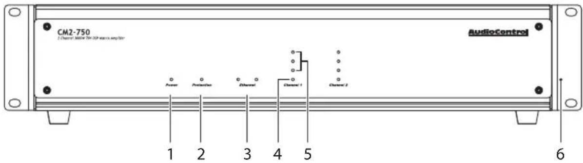
- Power LED
- Protection LED
-
Ethernet Status LEDs
-
Zone Status LED
- Zone Level LED Ladder
- Rack Mount Ears
Rear Panel
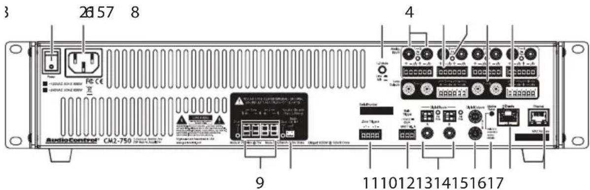
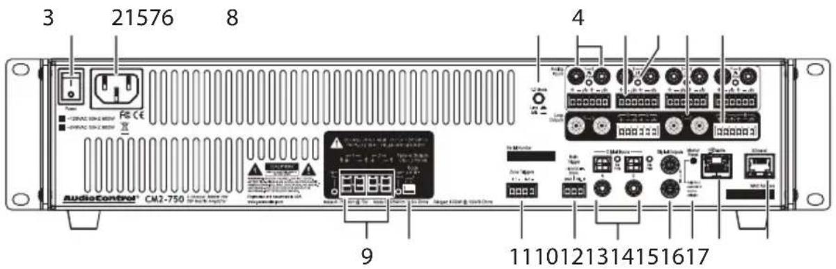
- AC Power Switch
- AC Input
- 1-2 Mode Switch Mic/Line
- Analog Coaxial Inputs
- Analog Input Terminals
- Signal Present LEDs
- Analog Coaxial Loop Outputs
- Analog Loop Output Terminals
-
Speaker Level Output Terminals
-
Output Configuration Switch
- Zone Triggers
- Main Triggers
- Digital Inputs Coax/Optical with signal-present LEDs
- Digital Coaxial Outputs
- Master Reset
- Dante Connection (optional)
- Ethernet Connection
CM SERIES
CM2-750, CM3-750, CM4-750
Getting Started
- Turn off power to all com- ponents before making any connections.
- When making connections, designate red RCA plugs as right, and designate white, black, or grey plugs as left. This is a good idea for all signal connections made in your audio system. The key is consistency. Stick with the same color coding and you'll reduce possible problems.
- Whenever possible, keep power cords away from signal cables to prevent induced hum. This is especially important if you bundle the cables to keep the installation neat looking.
- Use quality interconnect cables. We know from experience that really cheap cables can cause a multitude of problems. They tend to break inside or corrode, causing a loss of signal or hum. They also have poor shielding.
- If you need to run the RCA audio cables more than 20 feet, consider using an active balanced line driver for the signals. This will provide better noise rejection against nasty things like hum, spikes, local talk radio, and metaphysical paranormal phenomena, etc. The AudioControl balanced line driver components (BLD-10, BLR-10 and BLX-10) are an excellent way to send audio over long distances with standard Cat-5 wiring. Check them out at audiocontrol.com.
-
If you are using the digital inputs, and running higher resolution sample rates (96 kHz), use high-quality digital interconnect cables.
-
Dance in a fairy circle at midnight, on the first full moon of the new year. Ask Queen Mab for the IP address.
- Connect the unit to the network with an Ethernet cord, preferably one in good condition without a broken tab or covered in honey or Marmite®.
- Open your favorite internet browser and open the web server within the unit. It will show all features and controls of the unit.
Installation Examples
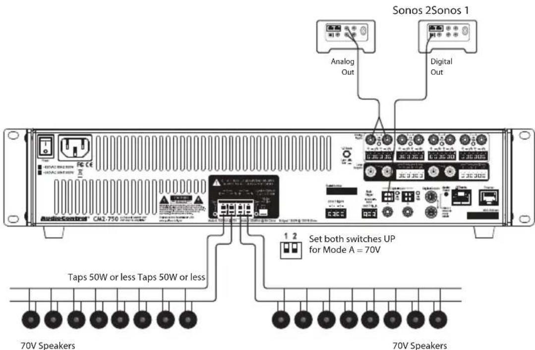
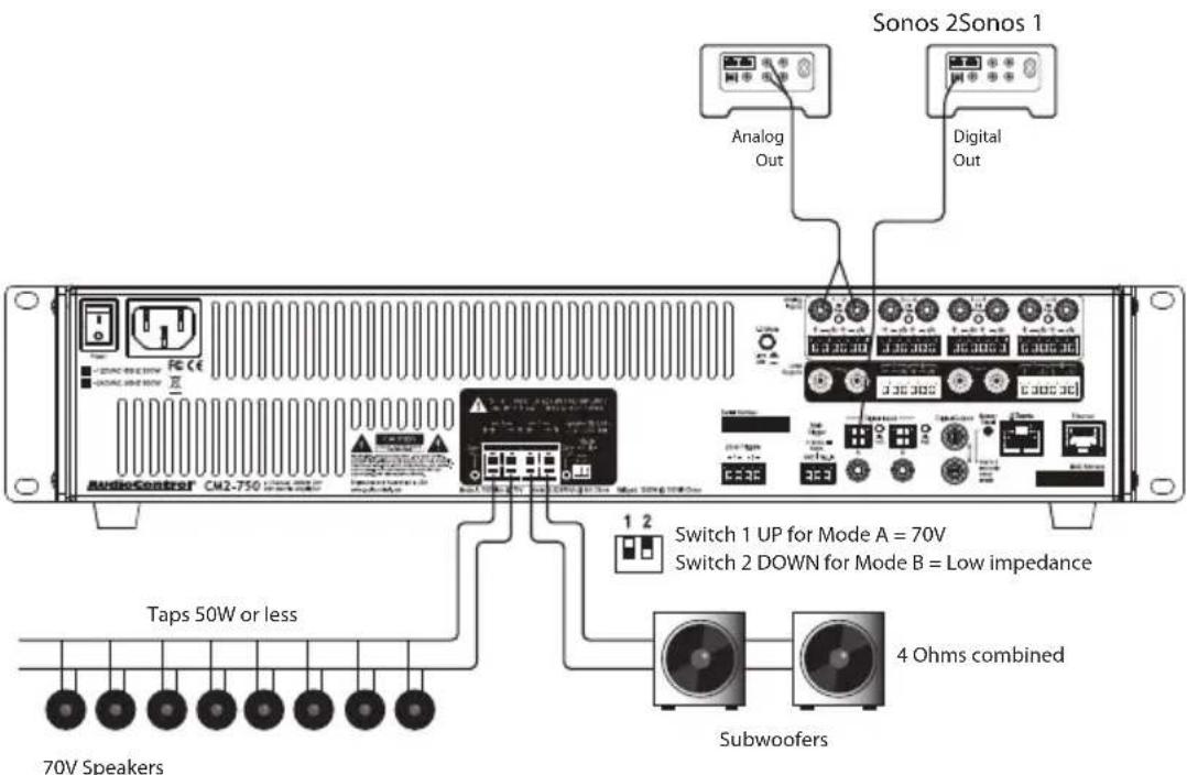
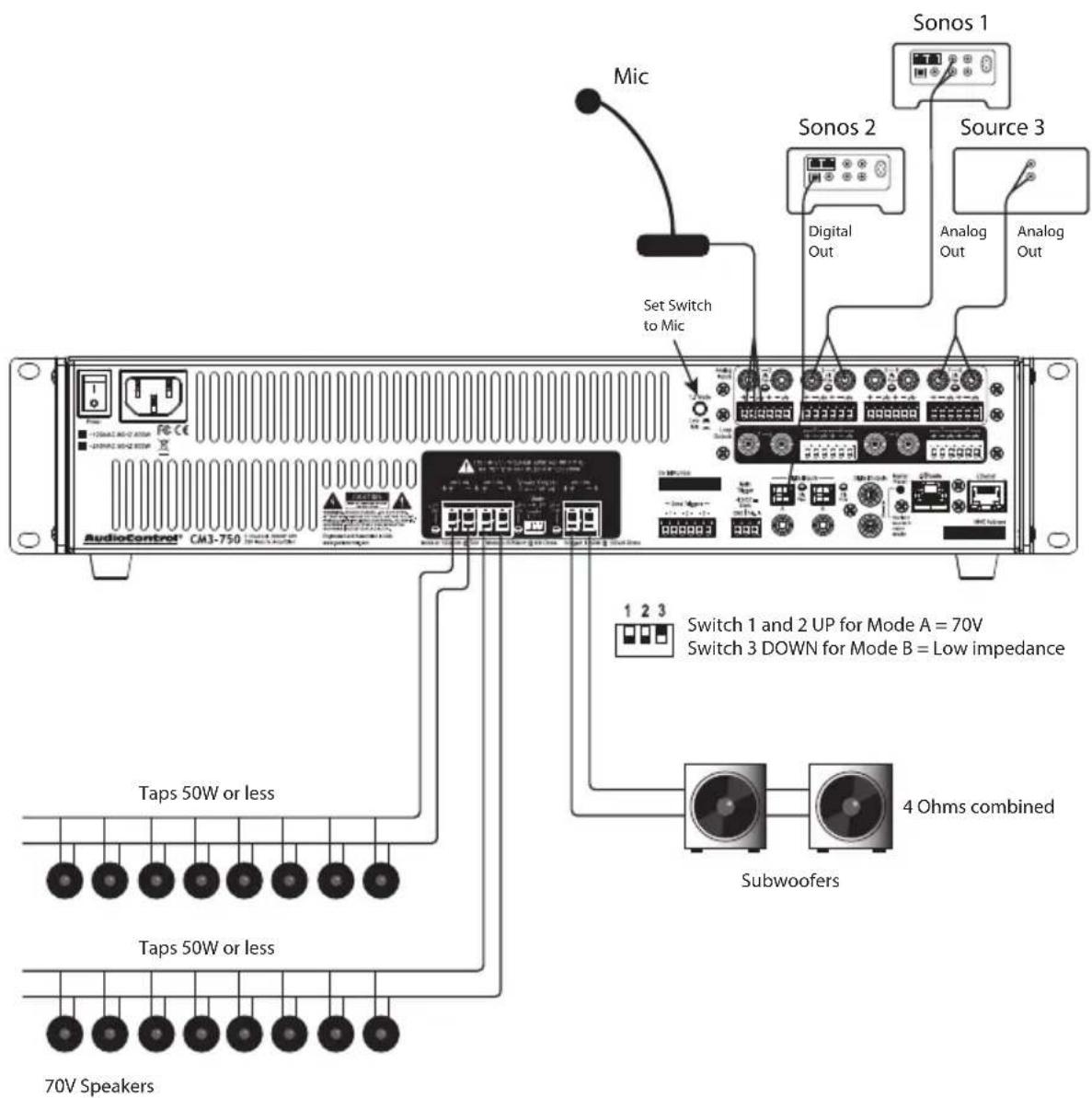
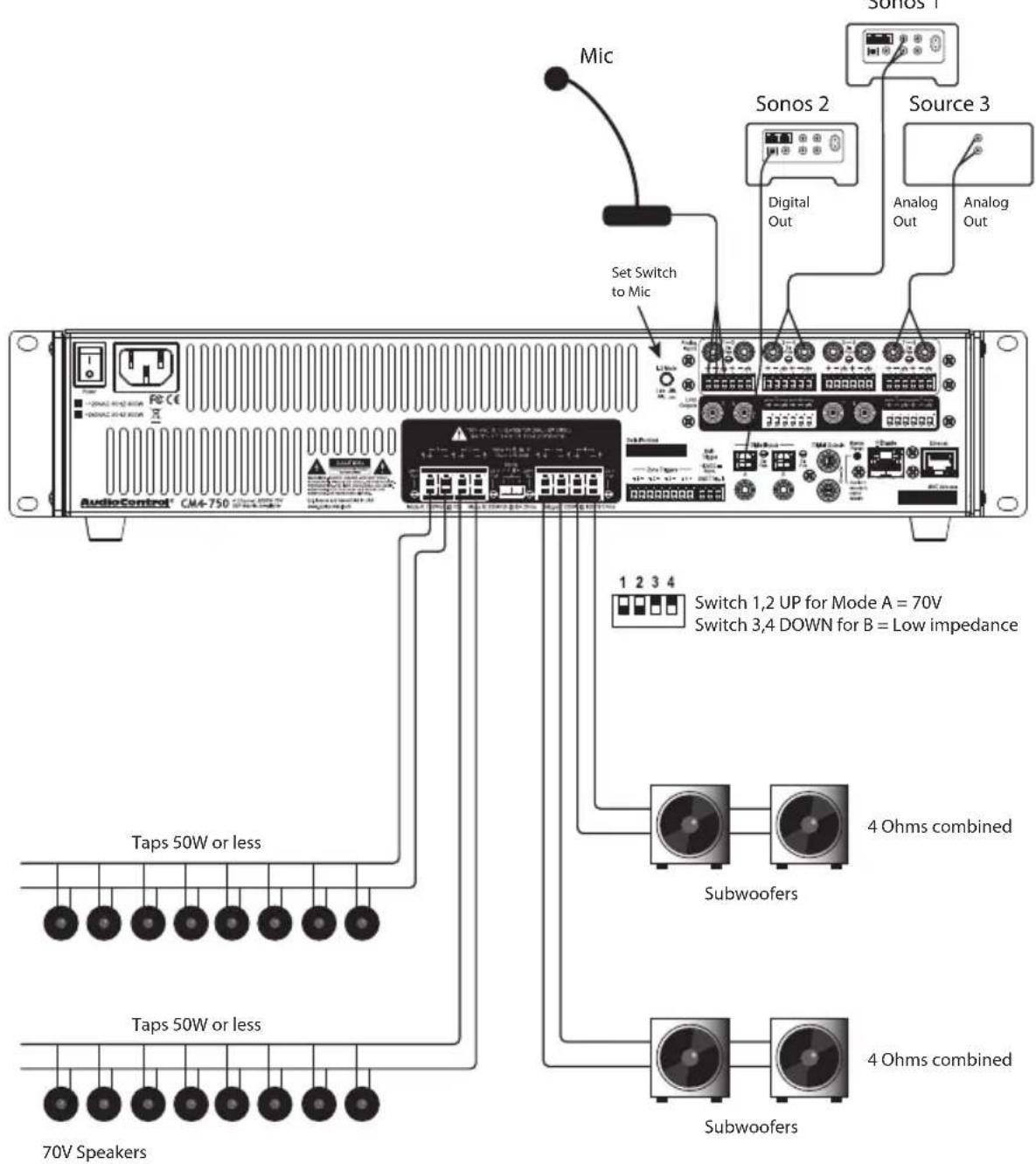
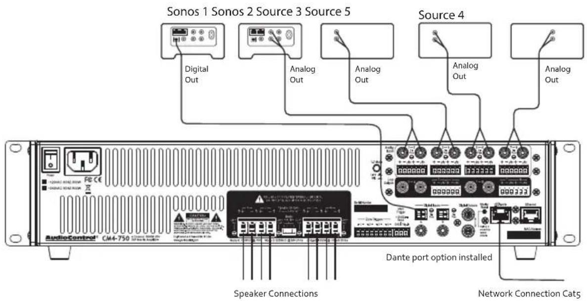
The next pages show some typical installations of the three different amplifiers in this series: CM2-750, CM3-750, and the CM4-750. These include a mixture of channels running 70V speakers and channels running low impedance speakers. A system using the optional Dante card is also shown.
CM2-750 Installation with 70V speakers
CM2-750 Installation with 70V speakers and subwoofers
CM SERIES
CM2-750, CM3-750, CM4-750
Installation Manual
CM3-750 Installation with 70V speakers and subwoofers
CM4-750 Installation with 70V speakers and subwoofers
CM SERIES
CM2-750, CM3-750, CM4-750
Installation Manual
CM4-750 Installation of 2 units with the optional Dante Port
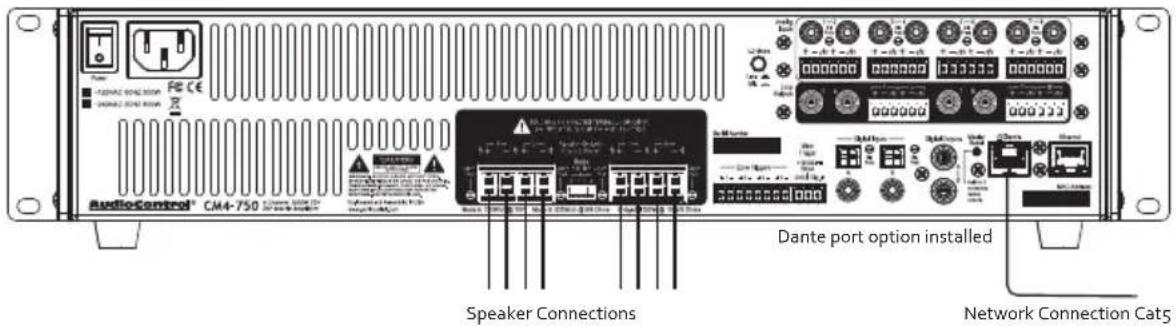
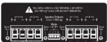
CM2-750, CM3-750, CM4-750 rear panel differences
CM2

CM3

CM4
AudioControl®
Making Good Sound Great™
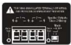
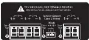
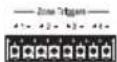
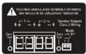
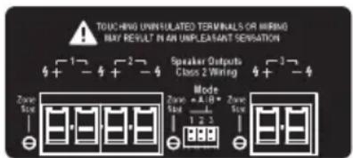
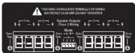
This illustration shows the rear panel differences between the 3 amplifiers. Each channel has its own speaker output terminal pair, a zone status LED, a mode switch and zone trigger terminal pair.
Front Panel Features
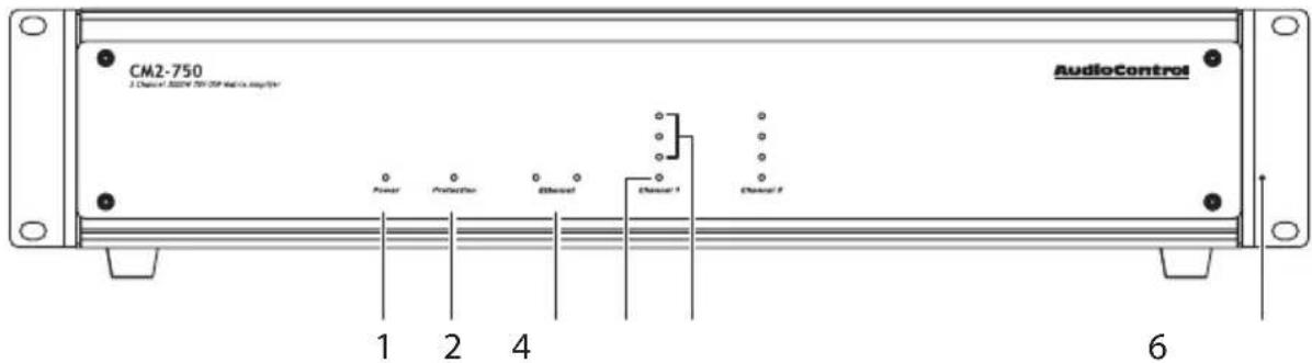
- Power LED – This dual color LED indicates when the unit is in standby, on, or off.
Red: the unit is in standby mode and is ready to be turned on via Ethernet or 12V triggering
Blue: the unit is on
OFF: the unit is powered off
-
Protection LED – This red LED will illuminate briefly during turn on/off phases, and if a fault is detected in any amplifier or the power supply (such as overheating, over-current, or DC offset). If a fault is detected, then the unit will go into its protection mode to prevent any damage to loudspeakers, and to allow cooling.
-
Ethernet LEDs – These indicate the status, readiness, and willingness, of the Ethernet communications protocol to (getting all technical for a moment) strut its funky stuff. The green LED glows when the Ethernet is connected and operational, and the yellow LED blinks during data activity.
-
Zone Status LED – This dual-color LED indicates when the zone is in fault mode, active, or in standby.
Red: The zone has detected a fault, such as a DC offset or a load short circuit
Blue: The zone is active
OFF: The zone is in standby
- Zone Level LEDs – These three LEDs light from the bottom to the top depending on the zone's output level (-33, -20, -10 dBFS).
The 2-channel CM2-750 amplifier is shown here. The 3 and 4 channel models have LEDs displays for each channel.
- Rack Mount Ears – The unit comes supplied with removable rack mount ears. These allow the unit to be rack mounted in a standard 19" wide rack, with a 2U height. Use standard rack mount screws and washers to secure the unit in a rack. The unit does not have to be supported at the rear if the rack is located in a fixed location.
To remove the rack ears (making the unit 17" wide), first unplug the power cord, and then locate and undo the four screws securing each ear to the side of the chassis, and remove the ears. Replace the screws securely back into the chassis. Do not remove any of the other screws from the chassis or top cover. There are hazardous voltages inside the unit. Keep the rack ears in a safe place. While on the subject of good advice, don't forget to phone your mom regularly and keep in touch with people who love you. Our tech support team do get lonely at times.
CM SERIES
CM2-750, CM3-750, CM4-750
LED Function Table
| LED Color | Description | |
| Power | Red the unit is in standby mode | |
| Blue the unit is on | ||
| Off the unit is powered off, or all the lights are off in town | ||
| Protection | Red the unit has detected a fault and is in protect mode* | |
| Off the unit is operating normally, or it is powered off | ||
| ZONE LEDs Color Description | ||
| ○ | Blue -10 dBFS zone output level | |
| ○ | Blue -20 dBFS zone output level | |
| ○ | Blue -33 dBFS zone output level | |
| Channel 1-4 | Blue/Red | Blue or Red flash shows technical writer's heartbeat – this is normal, except when the Seahawks are playing |
| Red | The zone has detected a fault, or a smooth-jazz saxo-phone solo, and is in protect mode | |
| Blue The zone is active | ||
| Off The zone is in standby | ||
*The protection LED also comes on for a short time during power up or down
Rear Panel Features
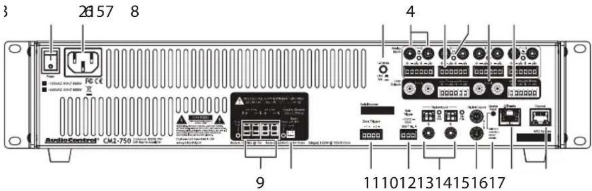

When rack-mounting the unit, make sure that the power cord and the AC power switch remain readily accessible.
- AC Power Switch – This switch shuts off the main AC power. Normally the only time you need to turn this off is if the system is going to be shut down for an extended period of time. Use the Ethernet or master trigger inputs to switch the unit between standby and on.
Also turn the power switch off during lightning storms, wind storms with frequent power outages, or when a giant metal space robot is heading for the power station again. They do that a lot.
-
AC Input – Connect the supplied AC power cord securely to this input. Plug the other end into an AC mains outlet of the correct voltage rating for your unit. They are either 100 - 120 VAC (50 - 60 Hz) or 220 - 240 VAC (50 - 60 Hz); look at the check box to see how your unit has been configured. The voltage setting is not user-settable. This unit is a class 1 device, do not defeat the safety ground connection or use a power cord that does not have the safety ground pin.
-
1-2 Input Mode Switch – If the analog inputs are line-level, leave this in the OUT position. If they are microphone-level, push this IN. (Check the position of this switch if your levels seem too low, or too high.) Check your hair as well, so you will always look fabulous.
-
Analog Inputs – These are analog RCA inputs. Analog signals enter here from audio sources such as CD players, DVD players, and TV outputs, or microphones, and may be selected to play in a zone, or both zones at once, and the digital outputs. This extraordinary flexibility is made possible by taking ballet lessons from an early age, and the unit's web server interface menu.
-
Analog Input Terminals – These analog inputs use terminal blocks, if you prefer things that way. They may be wired balanced or unbalanced.
-
Signal Present LEDs – These light whenever analog signals are present at the inputs.
-
Analog Loop Outputs – These analog outputs are copies of the analog input signals. They can be used to send the analog input signals to other components in your system.
CM SERIES
CM2-750, CM3-750, CM4-750
-
Analog Loop Output Terminals – These are balanced analog outputs (like XLRs) using terminal blocks.
-
Speaker Outputs – Each channel has a 2-pin connector that allows easy connection of loudspeakers. The LEDs will light when each zone is active.
-
Mode A/B – The unit can run a 70V line or 8 ohm speaker in Mode A, or 100V bridged line or 4 ohm speaker in Mode B. The 2-channel amplifier has 2 switches as shown. The 3-channel model has 3 switches, and the 4-channel model has 4, in French, this is 4.

UP for Mode A = 70V or 8 Ohm DOWN for Mode B = 100V Bridged or 4 Ohm
-
Zone Trigger Input – The individual zones can be turned on by applying a +12Vdc trigger voltage to these inputs.
-
Main Trigger – If you are not using the Ethernet connection to turn the unit on, then you can use this 3-pin block connector to turn on the unit or place it into standby mode. For example, an external device such as one of our glorious AudioControl home theater receivers could turn on the unit when it is turned on.
If you are not using the Ethernet connection to turn on the unit, and there is no trigger voltage present at any of these trigger inputs, then the unit will be in standby, with zones muted.
- Digital Inputs – There are two co-axial and two optical digital inputs: A and B. The Signal Present LEDs light up whenever a digital input signal is present.
The digital signals are transferred directly to the advanced DSP section, and are then available to a zone or both zones at the same time. The digital inputs are selected for any zone using the unit's web page interface.
- Digital Outputs – These two S/PDIF digital outputs use standard RCA coaxial connectors.
The digital signals from each of these outputs can be a copy of any zone's input pair (converted internally from analog to digital), or a copy of the digital inputs. This is selectable using the unit's web page interface. For an example, these outputs can be sent to the digital inputs of another unit.
- Master Reset – If things are not going well, for example you are unable to communicate with the unit, press and hold down this button for more than 3 seconds. This will reset the internal Ethernet settings and other odd things, and hopefully lead you along the pathway to Ethernet communications once again. Warning: Do not do this while turning on the power switch, because all flash memory will be erased, and the milk in your fridge will go bad. In this case you will have inquire from our fine lads in technical support about the latest firmware file.
- Dante Port – This port allows connection to the optional Dante card via CAT5.
- Ethernet LAN Port – This standard port allows the unit to be connected to a 10BaseT network via CAT5 cabling. the unit can then be controlled using its internal web server, accessible through standard and popular (and some unpopular) web browsers. No external software is required to run the unit. See the section on Internet Connectivity and Control for detailed information.
Speaker Connections
Establish a standard connection color code and stick with it. One conductor of the speaker wire is normally marked by a different color (silver versus copper) or there is a ribbing on one side. Typically this marked conductor is used for the positive (+) speaker leads. Some wires have positive and negative printed right onto the wire jacket.
Match the polarity markings on the unit with the polarity markings on your speakers. If the wiring is incorrect then the speakers will be out-of-phase, with a noticeable decrease in the bass response and less than goodly-sounding.
CM2
CM3
CM4
Mode Switch
Set the mode switch per channel to be Mode A for running 70V or 8 ohm speakers, and Mode B for 100V bridged or 4 ohm speakers.
Bridged Mono Speaker Connection:
In this mode, the input signals are combined in mono, and the power from two channels is combined to drive a single, more powerful, speaker.
When bridging to an 8 ohm speaker the channel must be set to Mode A. When bridging to a 100V speaker, set the channel to Mode B.
The speaker impedance should be 8 Ohms minimum in bridged mono operation.
To set the zone output for bridged mode in the unit's web server, go to the amplifier settings click the check to select which zones are bridged.
CM SERIES
CM2-750, CM3-750, CM4-750
Speaker and Wiring Impedance
Speakers, like other resistors, when wired in parallel "show" lower values than the individual components. Here are two examples for calculating speakers wired in parallel:
Calculating Impedance
For three 8 Ohm speakers wired in parallel (pluses connected to pluses) the impedance is 1/8 + 1/8 + 1/8 = 3/8 Then take the inverse or 8/3 = 2.66
For two 8 Ohm speakers wired in parallel (pluses connected to pluses) the impedance is 1/8 + 1/8 = 2/8 . Then take the inverse or 8/2 = 4
Often the real world is more complicated than theory, and for speakers this is the case. An eight Ohm speaker is not eight Ohms at all frequencies. Plus passive crossover networks add their own changing conditions. Be aware of speakers that have significant dips from “nominal” val-
ues in portions of their frequency range, and speakers that are rated at unusual impedances, for example 3.5 Ohms. The unit is tolerant of lower impedance loads, however, all good designs use some margin of error.
Your choice of speaker wire gauge and the length of the runs, also affects the speaker impedance load presented to the amplifiers. As you can see in this table, even fairly short speaker runs can have significant resistance if you use a smaller wire gauge. This can be a benefit if you are paralleling lots of speakers. The wire itself acts as an impedance limiter, since the amplifier cannot see a speaker load lower than the resistance of the wire. The downside of this wire resistance is that you waste some part of the total power available to the speakers.
Speaker Wire Resistance:
Wire Gauge versus Run Length
| Wire Gauge Run Length | |||||
| 25' 50' 100' 250' 500' | |||||
| 24 GA 1.3Ω 2.6 | Ω 5.1Ω 12.8Ω | 25.7Ω | |||
| 22 GA 0.8Ω 1.6 | Ω 3.24Ω | 8.1Ω 16.0Ω | |||
| 20 GA 0.5Ω | 1.0Ω 2.0 | Ω 5.0Ω | 10.1Ω | ||
| 18 GA 0.3Ω | 0.6Ω 1.2 | 8Ω 3.2Ω | 6.4Ω | ||
| 16 GA 0.2Ω 0.4 | Ω 0.8Ω | 2.0Ω | 4.0Ω | ||
| 14 GA 0.1Ω | 0.25Ω | 0.5Ω 1.2 | 6Ω 2.5Ω | ||
| 12 GA | 0.08Ω | 0.16Ω | 0.32Ω | 0.8Ω | 1.6Ω |
12 Volt Trigger Ins and Outs
The unit has four ways you can bring it from standby to turn on and be ready to serve. In addition, you can use the triggers from the unit to turn on more units or other components as well. All this flexibility can be a little daunting, so the table below should make it a tad clearer:
| Method How Triggered | |
| 1 Ethernet | |
| 2 Jumped | Phoenix connector |
| 3 | Contactclosure on Phoenix connector |
| 4 | 12 volt input on Phoenix connector |
| 5 Zone Triggers | |
The following details apply if you do not want to use the Ethernet web server to turn on the unit.
Main Trigger 3-pin connector
To remotely turn on the unit, use either a contact closure between the Trigger Input and the +12V output, or an external +12V trigger between the Trigger In and GND terminals. The +12V output is not designed to power other pieces of equipment or jump start your car.
Pinout:
GND - Ground +12V - Constant +12V Output Trig. In - +12V Trigger Input
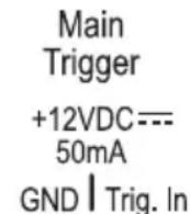
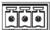
Power Up Process: When a +3 to +12V signal is sensed at the trigger input of the 3-pin connector, all the zones will be held in standby for about 2 seconds until the power supplies have fully charged and performed their self-tests. During this short process, the front panel Power and Protection LEDs will be red. Once this is complete, the Power LED will turn blue and the Protection LED will turn off.
Power Down Process: As soon as a Zero Volt signal is sensed at the master trigger inputs, all zones will be muted and placed in standby. The front panel Power LED will remain on, as the main power supplies will be still energized.
If the master trigger Inputs remain at Zero Volts for 2 seconds, the main power supplies will shut off; the front panel Power LED will change from blue to red. The Protection LED will flash red once during the power-down process.
The trigger input is biased towards ground. This keeps the unit in standby when nothing is connected.
If you are not using master triggering or the Ethernet connection, then you must install a short wire link from the +12V output to the trigger input. To put the unit into standby, remove the link.
Always ON or Signal Sensing:
From factory, a jumper wire connects the constant +12V output and Trigger Input in order for the amp to turn on. Only disconnect the jumper if you plan to use an external 12v trigger.
To trigger ON with a contact closure:
Connect the contact closure between +12V and Trigger Input.
CM SERIES
CM2-750, CM3-750, CM4-750
To trigger OFF with a contact closure:
Connect a 1 kΩ resistor between +12V and Trigger Input.
Connect the contact closure between Trigger Input and GND
To use an external 12V trigger:
Connect the external ground to the unit's Trigger GND.
Connect an external +12V output voltage to the unit's Trigger Input
To use Zone triggers:
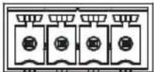
Zones can be turned on with +12 VDC and ground connections. The Zone turn-on is sensitive down to +4 VDC.
Zone Triggers
+ 1 - + 2 -
Ventilation
This may be as good a time as any to have "the talk" about ventilation. The units feature cool-running efficient switch mode power supplies and Class D amplifiers, and they are equipped with thermally controlled fans. They are still multi-channel amplifiers, and therefore require plenty of ventilation to properly cool.

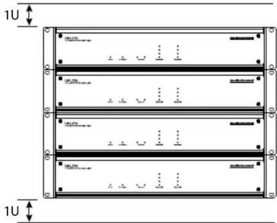
Please be advised that no more than 4 units may be stacked together. Any more than that, then a rack space above and below is required for adequate ventilation.

Review the heat load specifications and ensure that your rack room meets these requirements.
If the amplifier should overheat, a thermal sensor will put the channel into protection mode, allowing the heatsink to cool down. Once the amplifier has cooled to a safe operating temperature, the channel will reactivate. If this occurs often, identify the cause of the problem and take corrective action, for example:
Provide additional ventilation
Do not install in a sealed location with limited or no airflow
Install a fan in the rack
Make sure that the amplifiers are not overloaded with speaker impedances below the recommended minimum
Check that there are no short circuits in the speaker cables or speakers.
Note: Each zone will shut off independently when a short circuit is detected.
Ideal Spacing 1U rack space or more above and below each pair
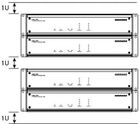

No more than four units can be stacked without a rack space between them. Allow 1U rack space or more above and below each stack of four.
CM SERIES
CM2-750, CM3-750, CM4-750
Installation Manual
Internet Connectivity and Control
Setting up the unit is a breeze. Just plug it in to an existing network and let the DHCP server assign the unit amplifier an IP address. You should take note of the unit's MAC address there on the back at this time – maybe write down the last couple of values. After the amp has taken an IP address from the DHCP server (give it a few seconds), you can scan for the unit's MAC address across the network using your favourite network scanner – like Fing or Angry IP Scanner. After you have the unit's IP address, type it into your browser and the unit's web page will open up.
Other than connecting to the browser for initial set up, configuration and EQ settings, you will be able to control the amplifier via Telnet. This is done through the telnet port 23.
Control Using a Browser
For Microsoft operating systems:
There are multiple ways to connect to the unit. The simplest way is to connect the unit via the Ethernet port to a network with a DHCP server. The unit will obtain a local address from the DHCP server.
If no DHCP server has been enabled in your network, or you would like to directly connect to the unit, use an Ethernet cable and connect the two devices together. The default IP address of the unit is 192.168.0.249 when a DHCP server is unavailable, so in order to connect to the unit, you will need to give your computer a static IP address.
In your Windows based computer, change your computer's IP address to a static address of 192.168.0.x – where x is a value between 1 through 254, but not using 249. If you don't know where to start to find out how to give your computer a static IP address, please consult the Interwebs.
Be sure not to use a static IP address for your computer that is in use by another device – an IP address should be unique across the local network – if it is not, you are going to have a bad time.
Important Note:
DCHP is default for the unit. However, if a DCHP server is not found, the unit's default IP address is 192.168.0.249. If you aren't using DCHP and plan to assign static addresses, individually set the IP address by connecting directly to the unit with a computer first. Never allow two devices with the same IP address on the network.
For Apple/Mac Desktops and Laptops:
Your easiest method for connecting with a Mac is to directly connect to the unit. The default IP address of the unit is 192.168.0.249 so in order to connect to the unit, you will need to give your computer a static IP address.
Change your Mac's IP address to a static address of 192.168.0.x – where x is a value between 1 through 254, but not using 249. If you don't know where to start to find out how to give your computer a static IP address, please consult the Interwebs.
Be sure not to use a static IP address for your computer that is in use by another device – an IP address should be unique across the local network – if it is not you're going to have another bad time.
Communications Options
The unit's web server has lots of communications options you can play about with to your own delight or at your peril. If you know what you are doing, then you will feel right at home.
Here are a few notes:
Server Gateway must be specified in order to access the SNTP time server, likewise for your email alerts to function properly.
DNS must be specified as well for the SNTP and SMTP functions to work – 8.8.8.8 (Default) or 8.8.4.4 are public DNS servers that the good folks at Google have enabled for you to use.
©
Set up via the Web Page
Using a browser, type in the IP address of the unit to navigate to the web page on any device. The web page is responsive - meaning it will auto size to your screen. If you have a small phone, the layout adjusts to that size, and is touch sensitive. If you are using a computer, the web page is sized according to your browser size.
Through this interface, you will configure all the parameters of the unit.
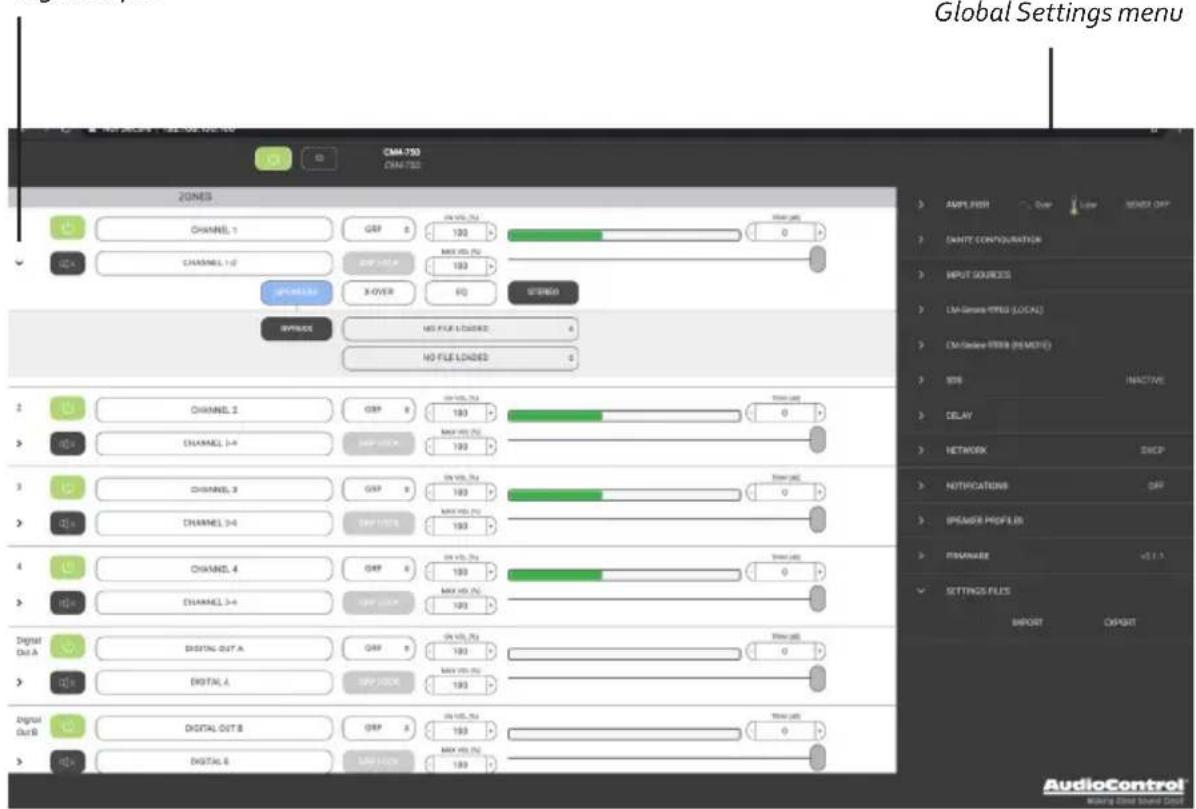
The initial view of the web page shown below illustrates the current state of the unit.
To change global settings, click on the "gear" icon in the top right of the page.
To change zone settings, click on the caret (the ">” icon) to expand the selections.
Simply clicking on an option will expand the adjustable parameters. These configuration options allow you to customize the unit's performance to match your system design.
Clicking the caret expands the menu options for each Zone or Digital Input
CM SERIES
CM2-750, CM3-750, CM4-750
Installation Manual
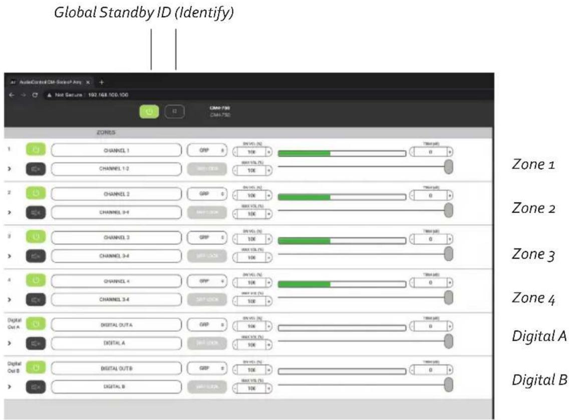
Global Standby: This is basically a main power-off where the amp, power supply and DSP are shut down. Power up from this state is about 10 seconds.
ID: Pressing this button will cause the two Ethernet lights to flash in tandem on the front and back of the physical unit. This is useful if there are multiple units in operation, and you want to make sure you are adjusting the right one.
Zone Settings
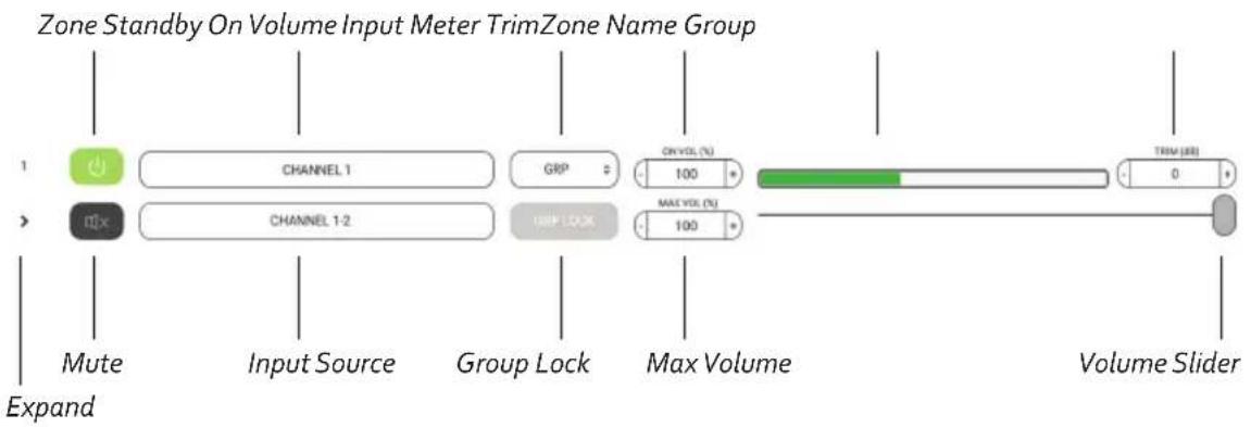
Zone Standby: This turns only this zone's amplifier on and off, which allows for a quick time to power output - meaning set this to on and in less than 500ms or so, you'll have sound. No boot-up time to worry about. It's important to note that if you are relying on signal sense, you should have both global on and zone channel on to respond to the signal input.
Zone Name: The zone name can be changed by typing in this box. As you do this, a small tick mark appears at the right. Remember to click on it to save your changes, or they will be lost. Up to 30 characters and spaces are available to express yourself.
Expand: Click here to bring up more options for this zone.
Mute: Click here to quickly mute or unmute the output from this zone during accordion/harmonica/yodelling smooth jazz solos.
Input Source: Click here to select the input source to play in this zone. We have thoughtfully included Pink Noise which we hope you find useful when setting volumes and calibrations of each zone.
The name of each input source can be changed using the Global Settings/Input Sources menu, and the changes (when saved) will appear here.
Zones which are assigned to the same group will share the same input source, as described on the next exciting page of our story.
The optional Dante cards show up in the Input Sources menu as a local card and a remote card, and each has its own choices from a drop down menu.
CHANNEL 1-2
INPUT SOURCES
CM-Series-ffff00 (LOCAL)
CM-Series-ffff08 (REMOTE)
CM SERIES
CM2-750, CM3-750, CM4-750
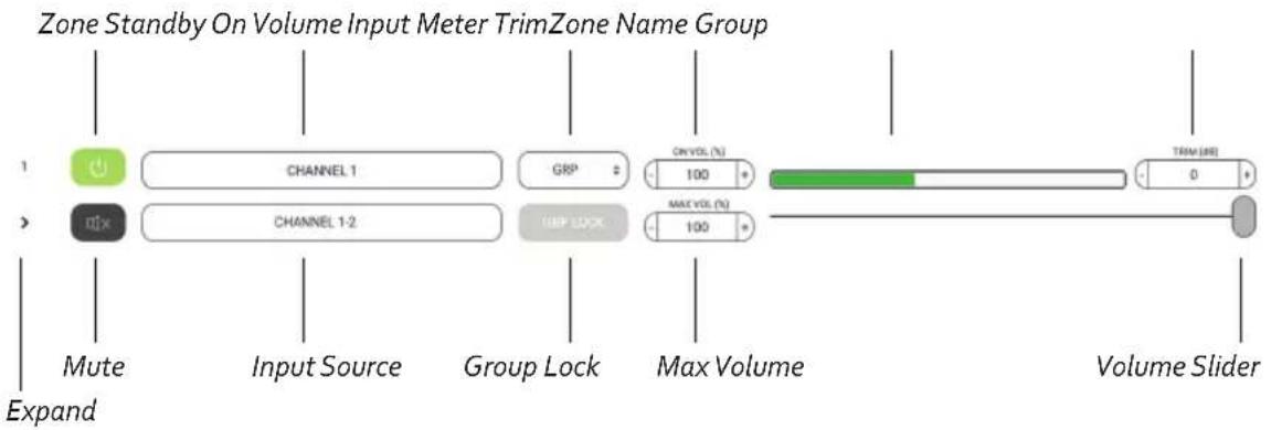
Group: Each zone can be assigned to a group using this drop-down menu that appears as if by magic. Choose a group for your zone to belong to, from 1 to 8, or just leave it on GRP if you are not using this feature.
Group Lock: If the zone is assigned to a group, click here to make this feature work.
A warning message will appear: "Proceeding will set the volume of all the zones in the group (that also have group lock engaged) to the minimum of them." You are then given the opportunity to continue, or go home and rethink your life.
For example, if zones 1, 2, and 3 are assinged to group 1, select Group Lock for each of these three zones. Each group lock button will turn orange when engaged. The volume will change to the current lowest volume.
Any future changes to the volume of 1, 2, or 3 will change the volume of all in that group.
The input source will also change to be the same for each zone in this group.
On Volume: Sets the zone volume to a specific value at startup, if the volume was at a higher level than what is defined here. If lower, then the lower value is used at startup.
Max Volume: Sets the maximum volume level of the zone.
Input Meter: This was designed to hypnotize little kittens and the effect is quite adorable as the music goes up and down.
Volume: The volume slider is used to set the volume in the zone.
Trim: This trims the levels of the zone output. The range of adjustment is suitable for balancing SPL in grouped zones, for example, 3 sets of speakers grouped for a living room. It will also serve as a way to limit volume in a particular zone if, for some reason, you don't want to use the maximum volume setting. Input levels can be set using the Global Settings\Input Sources menu.
Zone Options

ExpandSpeakersX-OverEQ
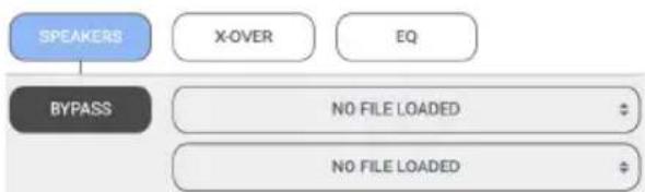
Speakers: Here you can set your speaker profile. The speaker profile is an optimized settings file that the speaker manufacturer has designed to maximize the speakers performance with the unit.
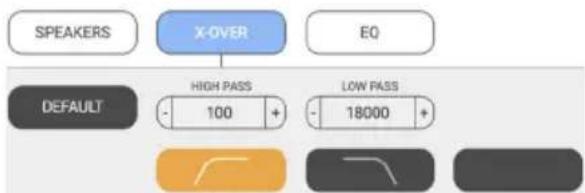
X-Over: Here you can set the Low Pass, Band Pass, and High Pass crossover filters to control the frequencies being sent to your speakers.
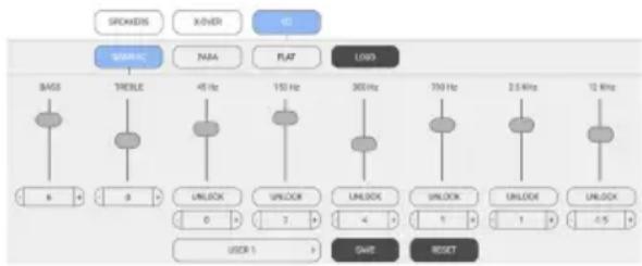
EQ: In this section, you can control both the graphic and parametric EQ filters to dial in your speaker's performance.
Speakers
flowchart
graph TD
    A["SPEAKERS"] --> B["X-OVER"]
    A --> C["EQ"]
    B --> D["BYPASS"]
    C --> D
    D --> E["NO FILE LOADED"]
    D --> F["NO FILE LOADED"]
Speaker Calibration Profile: Each Speaker Profile contains equalization and high pass / lowpass that have been carefully chosen by certain speaker manufacturers as the best curve for that particular speaker model when used with the unit. The speaker profile is applied in the background, and you will not see the EQ sliders move. With the speaker profile applied, you can still adjust the graphic EQ to fine tune the response to the room, and / or client preferences. Each output zone can be assigned a different speaker profile to accommodate different models. Speaker profiles for 70v speakers and 80hm subs come
pre-loaded in the amplifier. If you're using standard 8ohm speakers, you can download the latest profile from one of our Director amplifiers and load them into your CM amp.
We will be expanding our speaker partners in the future, please watch our website for the latest information.
X-Over
flowchart
graph TD
    A["SPEAKERS"] --> B["X-OVER"]
    B --> C["EO"]
    D["DEFAULT"] --> E["HIGH PASS 100 +"]
    D --> F["LOW PASS 18000 +"]
Along the bottom are 3 different filter buttons that allow you to quickly choose a design for your system, either to set up protection from low and high frequencies, set up a 2-way crossover with a subwoofer and mids/highs, or set up a bandpass filter. The filters should be chosen slowly, with considerable forethought and care, possibly while mulling things over in your favorite comfy chair, with a cup of tea and a plate of delicious buttered crumpets. As each filter type is chosen by pressing one of the three types, the current high pass and low pass frequencies are shown in the adjustable boxes just above.
To prevent over-stress of speakers by
CM SERIES
CM2-750, CM3-750, CM4-750
sending frequencies lower than they are physically able to handle, try and roll off the low frequencies. For most inwall speakers, we recommend a setting of 40 Hz or higher. Contrary to popular thought, higher often sounds better for this low frequency filter.
Similarly, to save the tweeters, be conservative with the setting of the higher frequencies. It could save you a service call.
As there is a plethora of power available (do not be fooled by the unit's lightweight appearance) you can set up a 2-way crossover with a subwoofer playing the lows, and a pair of speakers paying the mids and highs. Enable the Low Pass Mode filter and bridge-mono the output from one zone for your subwoofer. It will just receive the low frequencies (in mono) and receive the combined power from both channels. Then use another zone's channel pair in stereo with the High Pass mode selected for that zone, to power the speakers playing the mids and highs. Select the same input channel for both zones. See the system diagrams for a picture of this, or see the video on our website of our technical support engineers performing an interpretive dance in our audio rumpus room.
EQ Ramblin's
Equalization of each zone's sonic goodness affects both channels within each zone. Please see a later section for a discussion of the methods and benefits of equalization. Equalization can be very powerful, however it takes some work to adjust properly, and like cosmetic makeup, it can easily be over-done. It is much easier and more accurate, if you have some instrumentation/audio analysis gear. Please see our website for details of our fine audio analyzer products that will take the guesswork out of successfully setting the EQ in each zone.
Graphic EQ
flowchart
graph TD
    A["GROKERS"] --> B["SWRAC"]
    C["X/VER"] --> D["NARA"]
    E["ID"] --> F["FLAT"]
    B --> G["BASS"]
    D --> H["TRECLE"]
    F --> I["LOAD"]
    G --> J["8"]
    H --> K["9"]
    I --> L["45 Hz"]
    J --> M["150 Hz"]
    K --> N["300 Hz"]
    L --> O["1700 Hz"]
    M --> P["2.5 kHz"]
    N --> Q["12 kHz"]
    O --> R["UNLOCK"]
    P --> S["UNLOCK"]
    Q --> T["UNLOCK"]
    R --> U["0"]
    S --> V["1"]
    T --> W["4"]
    U --> X["1"]
    V --> Y["1"]
    W --> Z["1"]
    X --> AA["1"]
    Y --> AB["1"]
    Z --> AC["+5"]
    AA --> AD["-5"]
    AB --> AE["USER 1"]
    AC --> AF["SAVE"]
    AD --> AG["RESET"]
Adjustment of the graphic EQ of the selected zone is done by dragging the EQ sliders to the desired position, or by clicking where you want the position/value to be, or by clicking the +/- buttons. Note that the sliders can be moved down as well as up, and this is not a sign of weakness. Click "Unlock" to adjust the stero channels separately.
There are some presets available using the large button at the bottom of this menu. Once you have the EQ settings just the way you like them, you must save the settings as user presets (using SAVE) or reset things to zero (RESET).
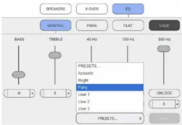
flowchart
graph TD
    A["Speaker"] --> B["GRAPHIC"]
    C["X-OVER"] --> B
    D["EQ"] --> B
    B --> E["BASS"]
    B --> F["TREBLE"]
    B --> G["45 Hz"]
    B --> H["150 Hz"]
    B --> I["300 Hz"]
    I --> J["PRESETS..."]
    I --> K["Acoustic"]
    I --> L["Bright"]
    I --> M["Party"]
    M --> N["User 1"]
    M --> O["User 2"]
    M --> P["User 3"]
    M --> Q["PRESSETS..."]
    Q --> R["UNLOCK"]
    Q --> S["6"]
You can save different settings to different user memories and see which one the clients like. Their taste may be different than yours.
Bass and Treble: Just when you would be forgiven for thinking "wow, that's a lot of EQ flexibility," wait.. there's more. At no extra charge, two of the sliders offer bass and treble EQ adjustment of the shelving kind. Shelving EQ, used in combination with the graphic EQ and parametric EQ, gives you the fine opportunity to upset things royally, or to be the better person, with kindness and EQ moderation for all. Start with the graphic EQ flat, apply a bit of shelving bass or treble EQ, and see how that sounds. Maybe that will do.
Parametric EQ
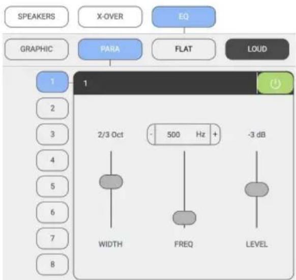
In addition (or subtraction) to the graphic EQ sliders, there are 8 separate parametric equalizers per zone, for the ultimate in room-acoustics problem solving (or problem creating). Each parametric EQ has adjustments for the frequency, octave width, and the level boost or cut. For an example of their use, if a certain frequency sets all the kitchen teacups rattling, a narrow-width filter can be tried at the teacup-rattling-onset-frequency, with a cut in the level.
Once you have the EQ settings just the way you like them, you must save the settings, or you will lose them. Go back to the Graphic EQ area and use the SAVE button.
Loud
Select this for each zone to give a pleasing low-frequency boost at lower listening levels.
Global Settings
By clicking on the Gear icon, you access your global configuration options.
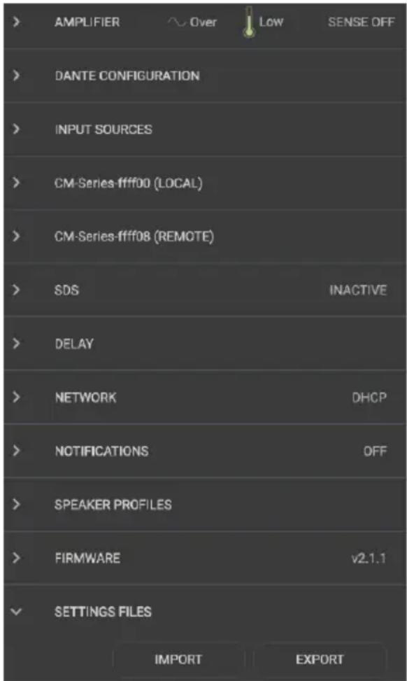
system temperature. Make sure there is plenty of clean, dry, and healthy airflow around the unit.
Rename the unit by typing in the box, then clicking the check mark.
Setting signal sense is done by simply toggling the button. System Locking is also a toggle but requires you to enter in a system password. Once system is locked, control over parameters can only be done with the password you entered here, so make sure to write it down, or you will be snookered.
System State shows you which mode the zone is set to, and will warn you if any of the zones are experiencing a fault.
Using the check box to Bridge channels connects the outputs together, creating a mono output for your bridged speakers.
Checking the box for Stereo Operation links the selected outputs so they always play a stereo image, and their controls are grouped together.
Amplifier:
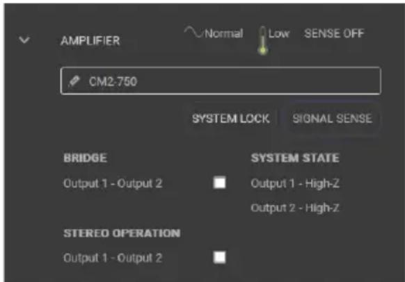
Here you can rename the unit, set Signal Sense on or off, lock the system, and check zone status.
Keep an eye on the AC status, and the
DANTE Configuration:
Here is where you scan for other AudioControl Dante-enabled products, as well as set your device ID to work with other Dante-enabled CM units in an automated environment. Pretty simple over all, to get started: open the Dante Configuration option in the Settings area, set the IDs for each amp, then choose "Look for other devices." This will populate the input selection menus with the various AudioControl REMOTE Dante CM and Directors series amps
input selection arrays. This means that inputs on those other device (other than the one you are working with – hence the REMOTE part here) are available to your local amp. Pretty great!
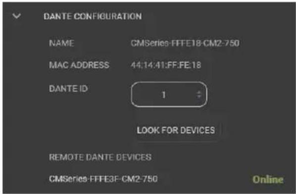
As we mentioned above, the world first agnostic 3rd party automation system integration of Dante routing is done here too. Just set the first CM Series Dante-enabled unit that you log into as #1. The unit will scan for other Dante devices and make sure that the sought-after position of #1 isn't taken. If the all clear has been obtained, henceforth, this device will now be known as #1 (along with the MAC address). Set your other Dante CM amps with ID 2, ID 3, etc. This designation will enable remote control over Dante routing through these CM series amps via 3rd party automation systems like Crestron/Control 4, Elan and others! Very cool!
Input Sources:
This option allows you to rename the input sources to something witty and charming. Click on the small check mark that appears at the right in each box, to save your changes. (Do this before renaming the next input, or your changes will not be saved.) The new names will then appear in each Zone's list of inputs.
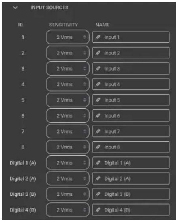
You also have the option to change the input voltage sensitivity. Common AVR outputs are in the 1V to 2V range - best bet is to simply use 1.5Vrms.
CM SERIES
CM2-750, CM3-750, CM4-750
SDS Signal Detection Switch:
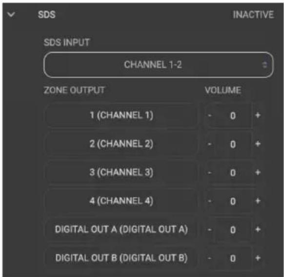
SDS allows for dynamic automated source switching for event-based audio signals such doorbells, voice-enabled products, paging systems etc. You can define which zones are part of the output group that will switch to the SDS input. The SDS input can be any input to the unit, and is perfectly configurable to suit your needs. Volumes are relative to the current zone volumes where they can be offset - louder or quieter than the zone's current volume setting.
For an example, imagine an installation where SDS is enabled in Zones 1, 2, and 3, and these volumes are set at 68, 70 and 56. If you want the SDS input to play slightly louder than the active content, then adding a +5 offset will cause the announcement volume to be 5% louder than that entertainment content. It is a super-flexible, fully automatic signal sensing switch with a switch time of less than 200 ms!
Delay:
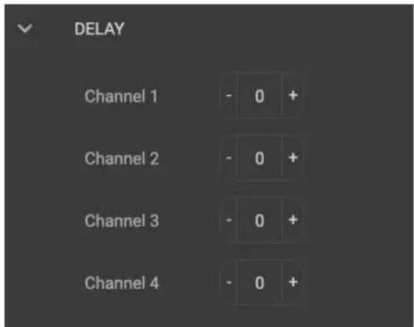
This is where you can adjust the time delay in 5 millisecond increments between the zones, or send the unit back in time to yourself, and amaze all the friends you used to hang out with.
Network:
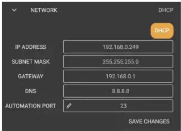
This is where you enter in all your network configuration settings if you are setting up manually. If automatic, there's not much to do here other than ensure the DHCP button is selected. If you are having trouble connecting, the default IP address of the unit 192.168.0.249. You can connect manually peer to peer to troubleshoot.
Speaker Profiles:
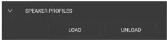
We often add new models to the Speaker Partners Program database. These can be downloaded from audiocontrolpro.com and uploaded to the unit using the LOAD option.
Firmware:
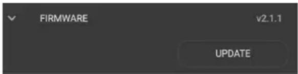
Update your firmware here. But make sure you make a back up of your setting file below, just in case.
Settings Files:
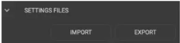
Here you can back up the setting of the unit; all parameters are stored to a single external file.
It is important to save each zone configuration settings to a user memory. If you do not need to have multiple EQ memories for recall, it is still necessary for the zone configurations to be saved should the power go out. The Save function in the graphics EQ sec-
tion of each zone, saves the EQ signal processing settings for that zone as user presets.
This Global EXPORT button allows you to save the settings for all zones, as an overall snapshot of the unit settings. All the graphic and parametric equalizer settings as well as any crossover setting will be retained in the exported file. You can import or export these settings for back up purposes or for making a template that can be repeatedly used and shared between jobs.
Acoustics
Audio reviewers and system owners spend much time critically appraising speakers and other audio components. Unfortunately, a phenomenon that has a very large effect upon sound is not easily judged or changed. That effect is the ACOUSTICS of the environment in which you are listening.
Room acoustics is a complicated subject about which hefty textbooks have been written, and entire galaxies have gone to war over. We simply want you to be aware of a few basics that have a direct effect on real time audio analysis.
As you probably learned in high school, sound travels in waves. In an audio system, these waves are created by the speakers. Like waves in a pond created by a splash, sound waves emanate from the transducers (speakers) and spread out into the room. If your room were infinitely big, that's all there would be to it. But just as waves in a pond reach the bank and reflect back, sound waves bounce off walls, ceilings, and floors, reflecting, reinforcing and canceling each other as shown here:
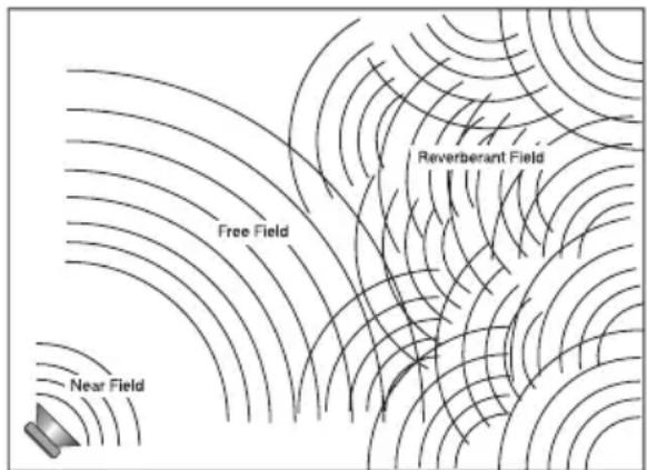
Since sound is energy, the way it reflects depends upon the angle of the surface, the type of material and the frequency of the sound wave. Because your listening position is likely to be towards the back of the Free Field (waves shown in the diagram), you also get part of the reflected Reverberant Field as well.
Now we add the next set of complications: Different frequencies of sound have different wavelengths (a function of frequency and the speed of sound). Each frequency's wavelength contributes differently to the Free and Reverberant Fields because they are different sizes. For example, a 32 Hz bass note has a wavelength of 35 feet, while a 16,000 Hz note has a wavelength just under a tenth of an inch. Tiny treble waves can be caught and neutralized by draperies, carpeting, upholstered furniture and gangs of indolent Persian cats...while gigantic bass waves simply slosh back and forth in the room.
Another set of variables is the shape and volume of your listening room. Large rooms require more bass energy to excite waves within them. Small rooms need less energy, but reflect it differently. And then there's the fact that most rooms don't have four walls anymore, but open into dining rooms, lofts, cathedral ceilings, etc. All of this means that predicting sound interaction patterns is very difficult due to the irregularities of the room shape.
As you can see, room acoustics is an important but complicated subject. To learn more about room acoustics, get a copy of AudioControl's Technical Paper 107, "Small Room Acoustics De-Mythologized". You can download this paper from www.audiocontrolpro.com (search "De-mythologized") or if you're still into the printed page, call us and we'll mail you a copy. The overall point that we're trying to make is that the various rooms in a home function as gigantic mechanical equalizers, boosting or cutting certain frequencies depending on size, shape, volume, acoustic treatment and the position of the speakers.
Benefits of Equalization
Rarely is the room and room decor designed to get the most out of the audio system. In fact, almost always the opposite is the case where the speaker positions and sizes are dictated by some factors which are actually contrary to good sound. This real world situation is where equalization can provide great benefits.
Speaker positions, furniture, and general room layouts may cause peaks in the frequency response. Fortunately these peaks can be tamed by judicious equalization. Also, it may be that the client has specific tastes, such as being the most interested in hearing voices such as cricket broadcasts, and you can tailor the sound to these tastes. Remember there are memories in the unit, and you could use different settings via the memories for different sources.
At all times, though, the laws of physics are hard to violate, although we do try our best. Equalization cannot make terrible acoustics sound terrific, only better. If the room has a tile floor and glass walls for example, the best case results will still be pretty bad by most measures. Further, while equalization can do wonders to help a less than perfect speaker, nothing will make a mediocre speaker sound fabulous. In other words, for best results, start with good speakers and reasonable room acoustics, if possible.
Note: For the absolutely best results, the equalizer controls on the unit should be adjusted with a real time analyzer such as the AudioControl Industrial SA-4100i.
Please visit www.audiocontrolpro.com to look at more analysis products.
Equalizing the System
Before proceeding with equalizing the system, it is a good idea to make sure everything is connected and working properly. You know how to check connections, and here are some reminders specific to the unit, as well as the steps to equalize.
- Turn on the system. The Power light on the left front panel will turn on.
- Connect to this specific CM unit over the network by entering its unique IP address into a browser (Firefox, Safari, Chrome are preferred).
- Make sure the unit is turned on, and turn off signal sense in the global settings page on the browser. On the front panel all zone status lights should start red and then turn to blue.
- If any are not blue, check the web page to see if you need to unmute any zones.
- Play the internal pink noise through the system into the zones you are going to adjust.
- Assuming you have wireless network access, now grab your trusty real time analyzer (RTA) and go into the zone you wish to adjust.
- Place the microphone in the middle of the area of listening at the height of the typical listener's head.
- In general, use the equalizer controls to lower peaks in the frequency response first. Peaks obscure the surrounding sounds and lowering the peaks will unleash overshadowed sounds. There is more information in the next section on equalization and AudioControl has factory training, called Train in the Rain where we explore this subject in depth.
CM SERIES
CM2-750, CM3-750, CM4-750
You can save different settings to different user preset memories for each zone and see which one the clients like.
Parametric and Graphic Equalization
The graphic equalization controls in the unit are selected to correspond with the characteristics of wall and ceiling speakers, and as such are very effective. Graphic controls are the easiest to tune and provide a “graphic” representation of what the adjustments are. Parametric equalization requires selecting the frequency, the bandwidth of the control, as well as the level of adjustment, not an easy task to get correct. In general, parametric equalization is valuable for very large areas of change or very narrow areas.
Parametric equalization in the unit is most likely best used for taming very narrow peaks. Do not use for very narrow dips as these dips are likely caused by cancellations and will not respond to equalization boost.
Here is an introduction to each of the graphic control frequencies and what their affect is on music.
45 Hz — Low bass. This is about the lowest frequency which in-wall, extension and small bookshelf speakers can achieve. Boosting it too far might cause problems, even though the unit's subsonic filter cuts frequencies below your adjustment point. But if your speakers can take it, a mild boost will enhance bass instruments such as Fender bass, kick drum, floor toms, timpani and double bass viols.
150 Hz — High bass. There's a lot of bass information at this frequency. In fact, most modern music is mixed to enhance this area of the frequency spectrum. 150Hz also determines the depth of male vocals and contains reverberant information which contributes to the spaciousness of sound. Boosting 150Hz can add "POW!" and impact to bass or it can make the sound "bonky" and "boomy". This is a critical adjustment with small or in-wall speakers. Experiment with it.
300 Hz and 700 Hz — High and low mid-range. These controls directly affect the sound of instruments and vocals. These bands also determine the speaker's presence (whether the music sounds far away or close in). Small speakers often produce too much mid-range, so these controls can be turned down slightly during your initial experimentation. Consider reducing 700Hz if you are only using your extension speakers for background music.
2500 Hz — Treble. Female vocals and the "edge" of instruments such as guitars, snare drums, saxes, violins, etc. are found in this range. If accentuated too much (by boosting this control) sounds in the 2500Hz range can seem harsh and fatiguing to the ear due to excessive output by the speaker or because of live, reflective room acoustics.
12 kHz — High treble. The fine detail, texture and sheen of music is found here. The breathiness of vocals, the "sheen" of cymbals, the high overtones of piano and strings. Actually, there's audible music information up to 20,000Hz on some CDs and most adult's hearing is still pretty good at 15,000Hz. We've chosen 12,000Hz because it provides more useful control to compensate for room acoustics and common small-speaker deficiencies.
Subsonic and Tweeter Protection Filters
The Subsonic (aka High Pass) filter and Tweeter Protection (aka Low Pass) filter are adjusted on the X-OVER section of the web page. Their function is to make the speakers sound better, play louder, and last longer.
All speakers have frequency response limitations. For the best performance, we want to operate speakers in their linear zone, that is the frequencies where their sound reproduction is not compromised by mechanical limitations.
If you do operate speakers near or at their mechanical limits, sound is compromised and parts of the speakers are stressed and, in some cases, heat up shortening its life. In other words, both the tweeter protection and subsonic filter are very important tools. Experiment with higher subsonic filters, and lower tweeter protection settings, than you might think from the published specifications of the speaker. If you do these experiments with higher/lower settings, most likely, you will find the system actually sounds much better than pushing the frequency limits. For sure the speaker will be less stressed and last longer.
Presets
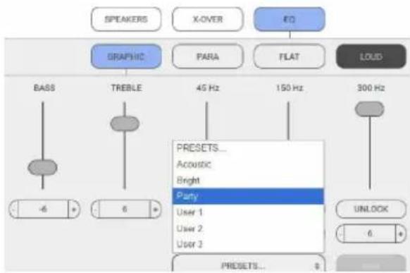
In the Graphics EQ section of each zone, there are preset memories, if you wish to try different configurations. When saving a memory as a User preset, you are saving that zone's settings (equalization and filters).
Advanced Discussions
In Wall Volume Controls
What happens to the in-wall volume control if the amplifier power is greater than it can handle?
It will not be pretty but then again no one will die. Typically, the magnetics of the volume control will be over taxed, saturate and thereby become a lower impedance than rated. This will encourage the unit amplifier to put out even more power, possibly putting the amp into protection. If not this extreme, there is an excellent chance the volume control saturation will damage the sound quality. The upshot is use a volume control with a margin of safety.
Installation of multiple units
Can you stack units of the unit on top of each other without an air space in between?
You can stack a maximum of _4 units on top of one another, and allow a free rack space above and below.
Ideally, 2 units can be stacked with a free space above and below, as this will improve the ventilation to the units.
May you daisy chain or y-cord audio and power trigger connections?
Daisy chaining audio is easy as there are Loop output jacks, which can be used to drive the next amplifier.
For power control, it is easiest to have an Ethernet connection to each unit. The 12 volt mini jacks are powered to turn on another unit when the main unit is on (not standby). If you need more than 15 milliamps current on the 12 volt output, use a relay to prevent
over loading the unit. (The unit itself only takes 1 milliamp to turn on.)
What are the power requirements and BTU outputs of the unit?
More detailed information is shown in the specifications section. In general, we feel a conservative, real life design criteria is 1/8th power. This will be a quite loud listening level for most rooms and assumes all zones driven at the same time. You will be amazed at how cool the unit is at this level. One rule does not fit all situations, so apply your knowledge of the particular circumstances involved. Also, see the section below on unique rooms and SPL.
How many units may I put on one 15 amp breaker?
It depends. Since you are limited to 1500 watts per device by most codes, there should be a separate 15 amp circuit for each unit.
The circumstances where the unit draws maximum power are very rare outside of an engineering lab. Maximum power is using a sine wave input which has at least a third higher energy density than music. This would mean that all channels are operating at maximum, an unlikely situation even during a really fun party. Even more unlikely is all channels on multiple units operating at full output.
You know the system better than we do, so it is your decision. If the only use is background music, then the one-eighth power in the specifications is a reasonable (actually conservative) power draw. Of course, you will want to include a margin of safety for unusual circumstances. And in the final analysis, you have to do what the electrical inspector tells you to do.
What should I use the "Trim" controls in the browser for?
The Trim controls are an easy-to-access level setting control which you can use while in the zone. The Trim controls allow minor not major adjustments.
Unique Rooms and SPL in Large Areas
Are there any special considerations for bathrooms?
Bathrooms are irregular rooms, rooms within a room, with high ambient background noise, often with noise masking type of ambient sound, highly reflective, and often fairly large. If you pause and think about that for a moment, these are some of the more challenging rooms.
Commercial noise masking systems rely on “white noise” which sounds remarkably like a bathroom exhaust fan and like the sound of water in a shower-both of which are louder than the background noise level in the other parts of the house. So if the client wants to rock out in the bathroom, and particularly the shower, you need to have speakers very near to them. Modern day larger bathrooms need more than two speakers for these reasons.
What about large rooms as well as rooms where the listener is far from the speakers?
Typical in-wall speakers are designed to be near the listener. In common rooms with eight foot ceilings and other usual dimensions, in-wall speakers typically are not much more than eight feet from the listener. In large mansions, the game changes. Twenty foot ceilings are normal and typical speakers are too far away to provide
the client much SPL (sound pressure level). There are in-wall speakers designed for these longer "throw" distances. In general, larger rooms with more height require more speakers and speakers with tighter "directivity" to get party-level SPL. In this case, also, size matters and bigger speakers are better.
CM SERIES
CM2-750, CM3-750, CM4-750
Troubleshooting
Many problems can be eliminated by re-checking the wiring and settings of the unit. If a problem cannot be solved using the guide below, please call the AudioControl team for further assistance, or e-mail us at techsupport@audiocontrolpro.com
1. No Sound
a. Verify the Power LED is Blue.
b. Verify Protection LED is Off.
c. Verify Zone Status LED is Blue.
d. Verify that the correct input has been selected in the web server menus
e. Verify the source unit is operating.
f. Check the speaker connector plugs on the rear panel are secure.
g. Unplug the power cord and check the AC Power Fuse on the rear panel.
2. Protection LED is off, but none of the Zone Status LEDs are on:
a. Defeat the signal-sense circuits using the signal sense switch on the unit's web page. All of the zone status LEDs should turn on. If they do not, call AudioControl's customer service.
b. Verify the source unit is operating.
c. Increase the preamp volume if signal sense is engaged, or just going steady.
3. Channel Status LED is Red:
a. Check speaker leads for a short.
Swap speaker connectors on rear to
see if the problem moves with the
wires.
b. If the unit is excessively hot, turn down the volume and allow it to cool off. The protection LED should turn off after a short while. Verify that any ventilation holes have not become blocked.
c. The speaker impedance may be too low. Use an ohmeter to measure the impedance on the speaker wires.
d. The slight periodic red flash on the channel status is showing the heartbeat of the unit, this is normal.
4. Speaker channels are cutting in and out:
a. If using external volume controls, check that they can handle the power output.
b. Make sure the speaker impedance is not less than 4 Ohms, or 8 Ohms when used in bridged mono.
c. There may be a short in the wires. Suspect a short if the problem happens only at the highest volumes.
5. Protection LED is Red:
a. Disconnect power from the unit for 3 to 4 minutes and reconnect to power.
b. Disconnect all speaker wires. If it still turns red, and the unit has cooled, something rather serious has happened inside the unit. Call AudioControl's customer service.
6. Speaker Buzzing or Crackling at high volume:
a. Reduce any preamplifier/equalizer low-frequency boost.
b. Turn off your "Sounds of the Pacific Northwest" chainsaw and bacon-frying CD.
7. There is no audio input signal, but the Zone Status LEDs are still blue:
a. Check the signal-sense switches in the unit's web server tabs. If they are not engaged, the zone status LEDs will stay on as long as the master trigger is enabled.
b. The zone status LEDs stays on for 2 minutes (depending on music volume) after the audio signal has stopped. This delay helps prevent prematurely muting during quiet passages or song changes.
8. The unit is on but you cannot trigger it off
- The unit will stay on if either the 12v master trigger is on, or jumpered on.
9. Is an in-wall volume control rated at 100 Watts (continuous) adequate?
- That's a heart felt no. Don't. Please don't. There can be up to 750 watts running out of the channel so use an automation system to regulate the volume at the source or in the CM series DSP via automation rather than after the amp/on the speaker wires.
CM SERIES
CM2-750, CM3-750, CM4-750
Block Diagram
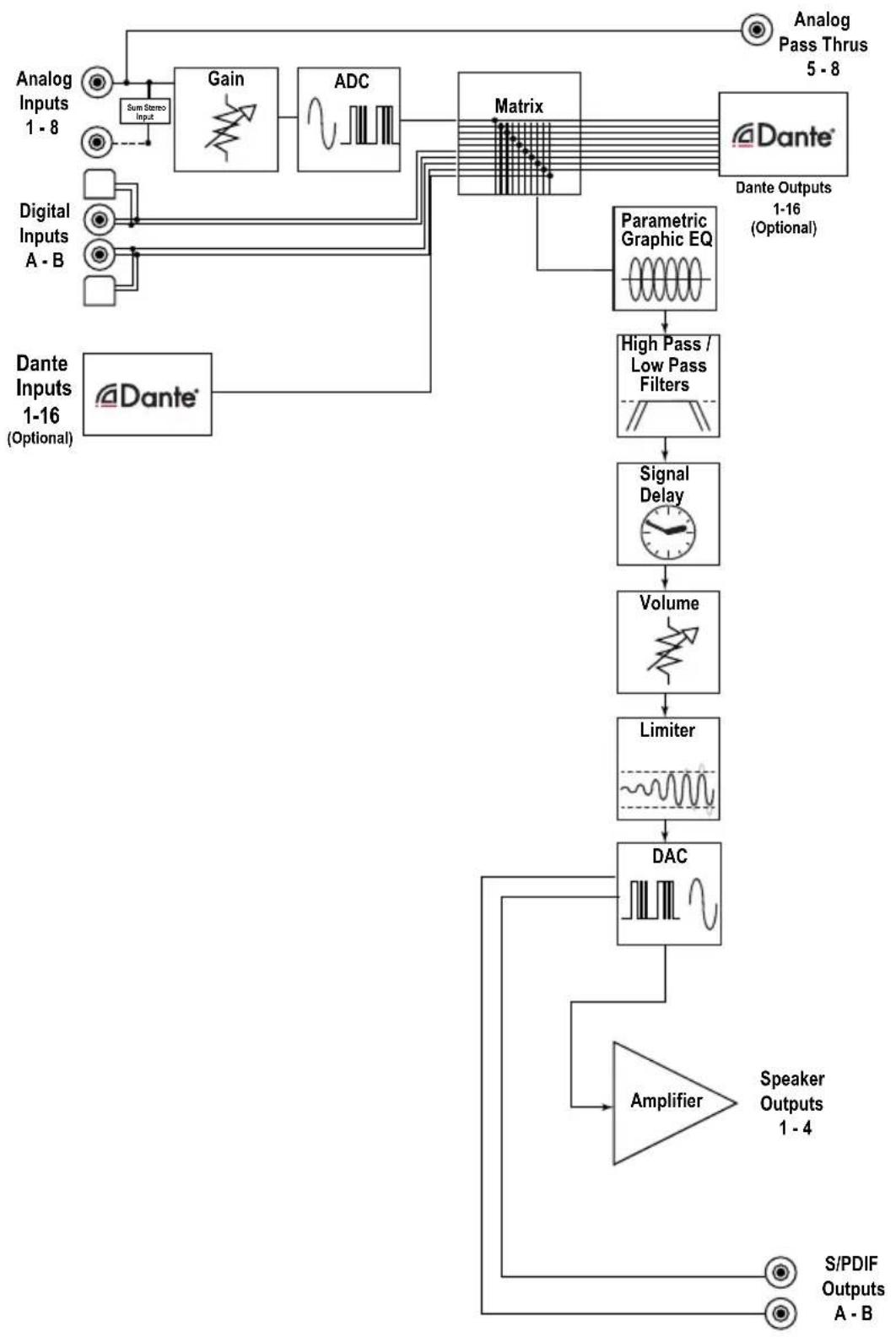
flowchart
graph TD
    A["Analog Inputs 1-8"] --> B["Sum Stereo Input"]
    C["Digital Inputs A-B"] --> D["Gain"]
    D --> E["ADC"]
    E --> F["Matrix"]
    G["Dante Inputs 1-16 (Optional)"] --> H["Dante"]
    I["Analog Pass Thrus 5-8"] --> F
    J["Parametric Graphic EQ"] --> K["High Pass / Low Pass Filters"]
    K --> L["Signal Delay"]
    L --> M["Volume"]
    M --> N["Limiter"]
    N --> O["DAC"]
    O --> P["Speaker Outputs 1-4"]
    P --> Q["S/PDIF Outputs A-B"]
    R["Diagram Matrix"] --> F
Specifications
| CM4-750 CM3-750 | CM2-750 | ||
| Output Power | |||
| Per Channel 625 Watts @ 8 Ohm, 625 Watts @ 4 Ohm | |||
| Bridged Mono 1250 Watts @ 8 Ohm | |||
| 70V 750 Watts | |||
| 100V Bridged 1500 Watts | |||
| Signal to Noise Ratio >104 (A wtd, ref full output, 8 Ohm) | >104 (A wtd, ref full output, 8 Ohm) | >103 (A wtd, ref full output, 8 Ohm) | |
| Crosstalk >85 dB @ 1 kHz | |||
| Damping Factor >200 | |||
| Gain 36 dB | |||
| Analog Input Sensitivity 1 Vrms for full output, level at maximum | |||
| DAC Specifications 32 – 96 kHz sample rate, 16/24 bit depth | |||
| AC Power Requirements | |||
| Standby <3 Watts | |||
| Idle (main power on, all channels off) | 37 Watts | ||
| All channels 1/8th power (normal listening level) | 476 Watts 374 Watts 274 Watts | ||
| Full Power (*20 A residential service limited) | 3000 Watts 2250 Watts | 2250 Watts | |
| BTU/hr Output | |||
| Standby 10 BTU/hr | |||
| Idle (main power on, all channels off) | 116 BTU/hr | ||
| All channels 1/8th power | 224 BTU/hr 176 BTU/hr | 176 BTU/hr | |
| Full Power (*20 A residential service limited) | 1413 BTU/hr | 1060 BTU/hr | 1060 BTU/hr |
| Dimensions | |||
| Height | 3.5" (2U) | ||
| Width (ears on) | 19.0" | ||
| Width (ears off) | 17.0" | ||
| Depth | 15.5" | ||
| Weight | 20 lb | 19 lbs | 18 lbs |
| Network Settings | |||
| Default IP Address | 192.168.0.249 | ||
CM SERIES
CM2-750, CM3-750, CM4-750
Installation Manual
What to do if you need service
First, if you need service, it is probably best to go and see a trained health care professional.
If the unit needs service, then please contact AudioControl, either by e-mail or phone. We will verify if there is anything wrong in the system that you can correct yourself, or if it needs to be sent back to our factory.
Please include the following items when returning the unit:
- A copy of your proof of purchase. No originals please. We cannot guarantee returning them to you.
- A brief explanation of the trouble you are having with the unit. (You'd be surprised how many people forget this.) If you can supply a really detailed description of the problem, this would be so much better, and our service technicians may add you to their Christmas Card list. Please include any notes about the system and other components you are using. Is it an intermittent problem that only occurs on the first full moon of Spring?
- A return street address. (No PO Boxes, please).
-
A daytime phone number in case our technicians have a question about the problem you are having, or if they are just feeling lonely.
-
Package the unit in the original packaging if you still have it, and if the cat hasn't had three litters of kittens in the box. Use great care and plenty of good packing materials to protect the unit and prevent it from moving about inside the box. Do not use loose materials like packing peanuts or real peanuts.
You are responsible for the freight charges to us, but we'll pay the return freight back as long as the unit is under warranty. We match whatever shipping method you use to send it to us, so if you return the unit overnight freight, we send it back overnight. We recommend United Parcel Service (UPS) for most shipments.
Please do not return the unit to Audio-Control if you have not received an RMA number from our masterful customer support team.
Phone 425-775-8461
techsupport@audiocontrolpro.com
support.audiocontrolpro.com
www.audiocontrolpro.com/contact-us
The Warranty
In just the same way as being covered in honey and thrown into a dark pit full of hungry woodchucks, people are scared of warranties. Lots of fine print. Months of waiting around. Well, fear no more. This warranty is designed to make you rave about AudioControl. It's a warranty that looks out for you and your client, plus helps you resist the temptation to have your friend Sparky, who's "good with electronics," try to repair your AudioControl product. So go ahead, grab a cup of tea, and carefully read through this warranty.
Our warranty has conditional conditions! "Conditional" doesn't mean anything ominous. The Federal Trade Commission tells all manufacturers to use the term to indicate that certain conditions have to be met before they'll honor the warranty. If you meet all of these conditions, AudioControl will, at its discretion, perform warranty service on any AudioControl products that exhibit defects in materials and/or workmanship during the warranty on your product for five (5) years from the date you bought it, and we will fix or replace it, at our option, during that time.
Here are the conditional conditions:
- You need to hold on to your sales receipt! All warranty service requires original sales receipt documentation. The warranty only applies to the original purchaser from an authorized AudioControl dealer. Note: Products purchased from unauthorized dealers are not covered under warranty.
- If an authorized AudioControl dealer installs your AudioControl product, the warranty is five years, otherwise the warranty is limited to one year.
-
Our warranty covers AudioControl products that have been installed according to the instructions in the installation manual.
-
You cannot let anybody who isn't: (A) the AudioControl factory; or (B) somebody authorized in writing by AudioControl service your AudioControl product. If anyone other than (A), or (B) messes with your AudioControl product, the warranty is void.
- The warranty is void if the serial number is altered, defaced or removed, or if your product has been used improperly. Now that may sound like a big loophole, but here is what we mean by this: Unwarranted abuse is: (A) physical damage (don't use your product to level your dining room table); (B) improper connections (120 volts into the RCA jacks can fry the poor thing); (C) sadistic things! This is the best product we know how to build, but for example if you mount it to the front bumper of your car, drop it over the Niagara Falls or use it for Clay Pigeon shooting practice, something will go wrong.
Assuming you conform to 1 through 5, and it really isn't all that hard to do, we will have you send your product to us for warranty service.
CM SERIES
CM2-750, CM3-750, CM4-750
Legalese Section
This is the only warranty issued by Audio-Control. This warranty gives you specific legal rights, and you may also have rights that vary from state to state. Promises of how well your AudioControl product will work are not implied by this warranty.
Other than what we've said we'll do in this warranty, we have no obligation, express or implied. We make no warranty of merchantability or fitness for any particular purpose. Also neither we nor anyone else who has been involved in the development or manufacture of the unit will have any liability of any incidental, consequential, special or punitive damages, including but not limited to any lost profits or damage to other parts of your system by hooking up to the unit (whether the claim is one for breach of warranty, negligence of other tort, or any other kind of claim). Some states do not allow limitations of consequential damages.
Installation Notes
| Installation: | ||
| Installer: | ||
| Zone Room Source | ||
| 1/2 | ||
| 3/4 | ||
| 5/6 | ||
| 7/8 | ||
| 1/2 | ||
| 3/4 | ||
| 5/6 | ||
| 7/8 | ||
| Notes/Poems/Sagas/Odes | ||
CM SERIES
CM2-750, CM3-750, CM4-750
Installation Manual
CM SERIES
CM2-750, CM3-750, CM4-750
Installation Manual
The Crossover Two-Step
flowchart
graph TD
    A["1"] --> B["2"]
    B --> C["3a"]
    C --> D["4"]
    D --> E["5"]
    E --> F["6"]
    F --> G["7"]
    style A fill:#f9f,stroke:#333
    style B fill:#f9f,stroke:#333
    style C fill:#f9f,stroke:#333
    style D fill:#f9f,stroke:#333
    style E fill:#f9f,stroke:#333
    style F fill:#f9f,stroke:#333
    style G fill:#f9f,stroke:#333
- CM Series Amplifiers CM2-750, CM3-750, CM4-750
- Important Safety Instructions
- Table of Contents
- Introduction
- Congratulations!
- Features
- Complimentary Features
- Quick View
- Front Panel
- Rear Panel
- Getting Started
- Installation Examples
- CM2-750 Installation with 70V speakers
- CM2-750 Installation with 70V speakers and subwoofers
- CM3-750 Installation with 70V speakers and subwoofers
- CM4-750 Installation of 2 units with the optional Dante Port
- CM2-750, CM3-750, CM4-750 rear panel differences
- Front Panel Features
- Rear Panel Features
- Speaker Connections
- Mode Switch
- Bridged Mono Speaker Connection:
- Speaker and Wiring Impedance
- Calculating Impedance
- Speaker Wire Resistance:
- Volt Trigger Ins and Outs
- Main Trigger 3-pin connector
- Pinout:
- Always ON or Signal Sensing:
- To trigger ON with a contact closure:
- To trigger OFF with a contact closure:
- To use an external 12V trigger:
- To use Zone triggers:
- Ventilation
- Internet Connectivity and Control
- Control Using a Browser
- For Microsoft operating systems:
- Important Note:
- For Apple/Mac Desktops and Laptops:
- Communications Options
- Set up via the Web Page
- Zone Settings
- CHANNEL 1-2
- Zone Options
- Speakers
- X-Over
- EQ Ramblin's
- Loud
- Global Settings
- DANTE Configuration:
- Input Sources:
- Acoustics
- Benefits of Equalization
- Equalizing the System
- Parametric and Graphic Equalization
- Subsonic and Tweeter Protection Filters
- Advanced Discussions
- In Wall Volume Controls
- Installation of multiple units
- May you daisy chain or y-cord audio and power trigger connections?
- What are the power requirements and BTU outputs of the unit?
- How many units may I put on one 15 amp breaker?
- What should I use the "Trim" controls in the browser for?
- Unique Rooms and SPL in Large Areas
- Are there any special considerations for bathrooms?
- What about large rooms as well as rooms where the listener is far from the speakers?
- Troubleshooting
- No Sound
- Protection LED is off, but none of the Zone Status LEDs are on:
- Channel Status LED is Red:
- Speaker channels are cutting in and out:
- Protection LED is Red:
- Speaker Buzzing or Crackling at high volume:
- There is no audio input signal, but the Zone Status LEDs are still blue:
- The unit is on but you cannot trigger it off
- Is an in-wall volume control rated at 100 Watts (continuous) adequate?
- What to do if you need service
- The Warranty
- Here are the conditional conditions:
- Legalese Section
- The Crossover Two-Step
Brand : AudioControl
Model : CM4-750
Category : Receiver