
DM812 - Hand blender Lectrosonics - Free user manual and instructions
Find the device manual for free DM812 Lectrosonics in PDF.


| Product Type | Hand Blender (Immersion Blender) |
| Brand | Lectrosonics |
| Model | DM812 |
| Power Consumption | 500 W |
| Voltage | 120 V / 230 V (dual voltage) |
| Speed Settings | 2 speeds (low and high) |
| Blade Material | Stainless steel |
| Shaft Material | Stainless steel |
| Immersion Depth | Up to 200 mm (8 inches) |
| Cord Length | 1.2 m (4 ft) |
| Weight | 0.8 kg (1.8 lbs) |
| Dimensions | 40 x 7 x 7 cm (15.7 x 2.8 x 2.8 in) |
| Safety Features | Auto shut-off when overheating; safety lock button |
| Maintenance | Detachable shaft for easy cleaning; hand wash recommended |
| Included Accessories | Mixing beaker (600 ml) |
| Noise Level | Approx. 75 dB |
| Ergonomic Handle | Soft-grip handle for comfortable use |
| Housing Material | ABS plastic |
| Warranty | 1 year limited warranty |
Frequently Asked Questions - DM812 Lectrosonics
User questions about DM812 Lectrosonics
0 question about this device. Answer the ones you know or ask your own.
Ask a new question about this device
Download the instructions for your Hand blender in PDF format for free! Find your manual DM812 - Lectrosonics and take your electronic device back in hand. On this page are published all the documents necessary for the use of your device. DM812 by Lectrosonics.
USER MANUAL DM812 Lectrosonics
HARDWARE and SOFTWARE INSTALLATION GUIDE
DM Series
Digital Audio Processors

Models:
DM1624F
DM1612F
DM812
Fill in for your records:
Serial Number:
Purchase Date:
Important Safety Instructions

This symbol, wherever it appears, alerts you to the presence of uninsulated dangerous voltage inside the enclosure -- voltage that may be sufficient to constitute a risk of shock.

This symbol, wherever it appears, alerts you to important operating and maintenance instructions in the accompanying literature. Please read the manual.
1) Read these instructions.
2) Keep these instructions.
3) Heed all warnings.
4) Follow all instructions.
5) Do not use this apparatus near water.
6) Clean only with a dry cloth.
7) Do not block any ventilation openings. Install in accordance with the manufacturer's instructions.
8) Do not install near any heat sources such as radiators, heat registers, stoves, or other apparatus (including amplifiers) that produce heat.
9) Do not defeat the safety purpose of the polarized or grounding-type plug. A polarized plug has two blades with one wider than the other. A grounding type plug has two blades and third grounding prong. The wider blade or the third prong are provided for your safety. If the provided plug does not fit into your outlet, consult an electrician for replacement of the obsolete outlet.
10) Protect the power cord from being walked on or pinched particularly at plugs, convenience receptacles, and the point where they exit from the apparatus.
11) Only use attachments/accessories specified by the manufacturer.
12) Use only with the cart, stand, tripod, bracket, or table specified by the manufacturer, or sold with the apparatus. When a cart is used, use caution when moving the cart/apparatus combination to avoid injury from tip-over.

natural_image
Silhouette of a person pushing a ladder inside a circle with a diagonal line (no text or symbols)13) Unplug this apparatus during lightning storms or when unused for long periods of time.
14) Refer all servicing to qualified service personnel. Servicing is required when the apparatus has been damaged in any way, such as power-supply cord or plug is damaged, liquid has been spilled or objects have fallen into the apparatus, the apparatus has been exposed to rain or moisture, does not operate normally, or has been dropped.
15) WARNING -- TO REDUCE THE RISK OF FIRE OR ELECTRIC SHOCK, DO NOT EXPOSE THIS APPARATUS TO RAIN OR MOISTURE.
Table of Contents
Important Safety Instructions.... 3
Introduction......5
Unpacking the Unit....5
Items Included in the Box: 5
Hardware Installation 6
Installing the DM System into a Rack 6
Audio Inputs 6
Audio Outputs 7
Programmable Inputs....8
Programmable Outputs....8
Expansion I/O ports 8
Master/Slave Configuration....9
Control System Interconnections....11
Installing LecNet2™ Software and USB Driver 12
Installation with LecNet2 Device Installer 12
USB Driver....14
Initial Setup 16
Service and Repair 18
NOTE: This equipment has been tested and found to comply with the limits for a Class B digital device, pursuant to Part 15 of the FCC Rules. These limits are designed to provide reasonable protection against harmful interference in a residential installation. The equipment generates, uses and can radiate radio frequency energy and, if not installed and used in accordance with the instructions, may cause harmful interference to radio communications. However, there is no guarantee that interference will not occur in a particular installation. If this equipment does cause harmful interference to radio or television reception, which can be determined by turning the equipment off and on, the user is encouraged to try to correct the interference by one or more of the following measures:
- Reorient or relocate the receiving antenna
- Increase the separation between the equipment and receiver
- Connect the equipment into an outlet on a circuit different from that which the receiver is connected
- Consult the dealer or an experienced radio/TV technician for help
Changes or modifications to this equipment not expressly approved by Lectrosonics, Inc. could void the user's authority to operate it.
Introduction
The purpose of this guide is to assist in the setup and operation of a typical DM system. This guide assumes familiarity with the DM Series Digital Audio Processors, its components and software menus and setup screens. To get the most out of the DM system, it is suggested to review the information presented in the DM Series Reference Manual.
A detailed online Help is also available to assist in the setup and operation of a DM system using the USB interface and a Windows® XP, Vista or 7 operating system. In addition to assistance setting up and operating the DM system, the Help includes a complete listing of the DM General Commands. These commands can be used to setup and operate the DM system via external devices using either the USB or RS232 serial port.
Unpacking the Unit
Compare the packing list enclosed with the unit with the original order. Inspect all items for damage. Immediately call 1-800-821-1121 to report any items that are missing or damaged. The sooner we get notified, the sooner we can get any needed replacement items shipped to your location.
Items Included in the Box:
- Installation Guide
- Power cable
- 5-pin de-pluggable connectors: 20 each for the DM1624 14 each for the DM1612 10 each for the DM812
- CAT-5e cables (2 each) 12" with shielded RJ45 connectors
• Lectrosonics screwdriver - DB9 to TRS (Stereo mini) cable – BLACK - for laptop setup
- DB9 to TRS (Stereo mini) cable – RED - for touch panel control systems
- USB cable
If there are any problems or items missing, immediately call 1-800-821-1121 and ask for anyone in sales or service.
Hardware Installation
Installing the DM System into a Rack
The DM1624F and DM1612F occupy two rack spaces. The DM812 occupies a single space. Mount with 4 rack screws using the appropriate mounting holes. It is recommended to use nylon washers to prevent damage to the front panel's finish when tightening the screws.
Do not obstruct the fan port on the 2RU models.
For North American installations, connect the Power Cable supplied with the unit between the DM and a stable power source. DM processors have internal switching power supplies that can tolerate voltages ranging from 100 VAC to 240 VAC. Use an approved power cable for installations outside North America.
Cables
It is recommended to use lacing bars for cable strain relief when mounting in a rack. Use only professional audio cable with proper shielding - typically, two conductor plus ground/shield.
Audio Connections
The analog audio inputs and outputs are connected through 5 pin de-pluggable connectors. Strip the insulation back 1/8 to 3/16" but do not tin (apply solder to) the leads. Insert the wire into a de-pluggable connector, leaving less than 1 mm of bare wire exposed, then tighten the retaining screw.

Note the labeling on the DM Chassis for the positive and negative leads. Ground is shared between two connections (the center pin). For balanced connections, all three leads can be connected.
NOTE: The DM Series does not have a "pin 1 problem."
Audio Inputs
Unbalanced Sources
Unbalanced audio sources (positive and ground) include items such as consumer VCR's, DVD players, etc., and may use both two wire and three wire cables. In either case, the positive output from the source should be connected to the appropriate positive (+) input on the DM. The shield or negative (−) output should be connected the DM's negative (−) input. Two wire cables should have a jumper between the DM negative input and ground. Three wire cables should have the shield connected to the DM's ground input and the shield and negative (−) leads joined together at the unbalanced source end.
WARNING: Do not activate phantom power for unbalanced sources. Refer to online help files after the software is installed.
Balanced Sources
Balanced differential sources from external equipment and microphones should be wired according to Balanced source to DM input (3-Wire). (See illustration.) When connecting balanced sources to the DM, it is important to not connect chassis ground (shield) to either signal conductor.


Phantom Power
The DM supplies +15 VDC phantom power to the audio inputs via a programmable switch and two 2 k resistors. (See illustration below.)
However, the true phantom power available at the microphone may be less due to voltage drop across the microphone itself (source resistance). In some cases, the voltage drop may be enough to result in marginal performance. The following formula can be used to determine how much phantom power will be available to a particular microphone.
$$ V _ {p h} = 1 5 \mathrm{V} - (1 k) \left(I _ {\text { mic }}\right) $$
Where:
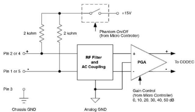
Programmable Gain Preamplifiers with Software Switchable Phantom Voltage
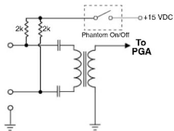
Equivalent Circuit
V_ph = the actual voltage available at the microphone. (Microphone specifications list this as the minimum recommended phantom voltage value. To minimize problems, the calculated Vph should exceed this value.)
I_mic = the current draw of the microphone. (Refer to individual microphone specifications for this value.)
Examples:
Microphone Number 1;
From Specification Sheet: V_ph(min) = 11 V I_mic(typical) = 4 mA
$$ \begin{array}{l} V _ {n h} = 1 5 \mathrm{V} - (1 \mathrm{k}) (. 0 0 4 \mathrm{A}) \ V _ {p h} ^ {p h} = 1 5 \mathrm{V} - 4 \mathrm{V} = 1 1 \mathrm{V} \ \end{array} $$
Since the calculated Vph is equal to Vph from the microphone specification sheet, this is a marginal situation.
Microphone Number 2:
From Specification Sheet: V_ph() = 9V I_mic(.) = 2mA
$$ \begin{array}{l} \mathrm{V} _ {\mathrm{ph}} = 1 5 \mathrm{V} - (1 \mathrm{k}) (. 0 0 2 \mathrm{A}) \ \mathrm{V} _ {\mathrm{ph}} = 1 5 \mathrm{V} - 2 \mathrm{V} = 1 3 \mathrm{V} \end{array} $$
Since the calculated Vph is greater than the Vph from the microphone specification sheet, this is an acceptable situation.
Audio Outputs
All outputs are a balanced differential configuration. Some outputs include an attenuator to reduce the signal to mic level. Use the outputs marked as MIC/LINE OUTPUTS for mic level applications. Using the other outputs marked LINE OUTPUTS with control panel attenuation can result in up to 40 dB of additional noise.
NOTE: Using a Line Output with digital attenuation applied with the Control Panel to achieve Mic Level will result in added noise.
When the DM output is connected to a balanced input, wire it as indicated in DM Out to Balanced Input (3-Wire). Select Mic or Line (as appropriate) either from the front panel LCD interface or via the software GUI.
When the DM output is conencted to an unbalanced input, wire it as indicated in DM Out to Unbalanced Input (3-Wire), or DM Out to Unbalanced Input (2-Wire).

DM Out to Balanced Input (3-Wire)

DM Out to Unbalanced Input (3-Wire)

DM Out to Unbalanced Input (2-Wire)
Programmable Inputs
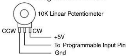
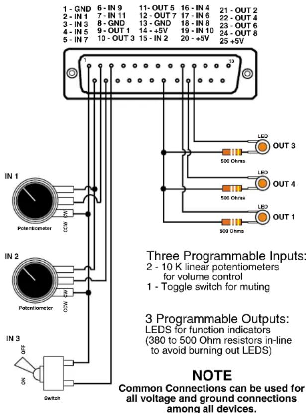
Programmable inputs are provided to enable external control over a variety of parameters. Each input can respond to either a contact closure or a continuous voltage. The following illustrates common connections to the programmable input pins. (See also Programmable Inputs and Outputs Wiring Diagram.)
Potentiometer Connection for Analog Control of Gain
Contact Closure as Programmable Input

DC Voltage Source as Programmable Input
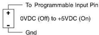
No external pull-up resistors are necessary because each programmable input is internally pulled up through a 100K resistor to +5V. When using a continuous voltage with one of the programmable inputs, the function of the programmable input must be set to either Analog In Control or Analog Out Control on the Programmable Inputs control tab in the Control Panel GUI. See the Programmable Input tab in the Control Panel software Help for setting all programmable input parameters.
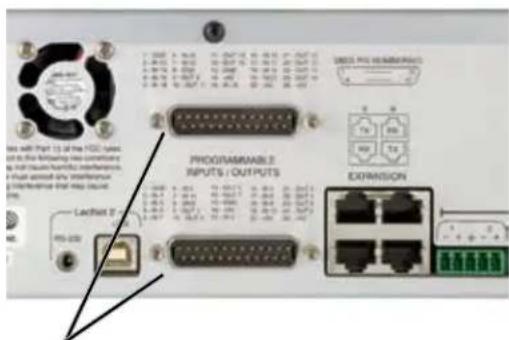
Programmable Inputs and Outputs (DM1612F shown)
Programmable Outputs
Programmable outputs are used to indicate either channel activity or the current state of a programmable output. Each programmable output is the electrical equivalent of a contact closure to ground. When a programmable output is "active", it conducts current to ground. When the programmable output is "inactive", no current flows to ground. The maximum usable voltage for the programmable outputs is 40 V and they will safely conduct up to 100 mA DC continuous. Following are some typical uses for the programmable outputs.
Note: The diagram shows an external DC source powering the relay coil. This is necessary whenever coil voltages exceed 5 V.
Both LEDs and 5V relay coils can be powered by the +5 V DC pins on the programmable input connector, as long as the maximum combined current for all LEDS and relay coils does not exceed 100 mA.
Programmable Input/Outputs Connections
Looking at the male connector on the rear panel of the processor, the pinouts are as follows:
LED is on when the programmable output is active

LED is off when the programmable output is active

Relay is on when the programmable output is active

Expansion I/O ports
The four RJ45 connectors on the rear panel are used to interconnect LecNet2™ units together. These ports are only used to transfer digital audio information via the Digital Audio Network Interface (DANI) between the units.

WARNING: The Expansion I/O connectors are NOT EtherNet, CobraNet or any other network based device interconnects. Connecting them to Ethernet, CobraNet or other network based device may cause damage to either unit.
| 1 - GND | 6 - IN 20 | 11 - OUT 13 | 16 - IN 15 | 21 - OUT 10 |
| 2 - IN 12 | 7 - IN 22 | 12 - OUT 15 | 17 - IN 17 | 22 - OUT 12 |
| 3 - IN 14 | 8 - GND | 13 - GND | 18 - IN 19 | 23 - OUT 14 |
| 4 - IN 16 | 9 - OUT 9 | 14 - +5V | 19 - IN 21 | 24 - OUT 16 |
| 5 - IN 18 | 10 - OUT 11 | 15 - IN 13 | 20 - +5V | 25 - +5V |

LOGIC I/O CONNECTIONS UPPER CONNECTOR
| 1 - GND | 6 - IN 9 | 11 - OUT 5 | 16 - IN 4 | 21 - OUT 2 |
| 2 - IN 1 | 7 - IN 11 | 12 - OUT 7 | 17 - IN 6 | 22 - OUT 4 |
| 3 - IN 3 | 8 - GND | 13 - GND | 18 - IN 8 | 23 - OUT 6 |
| 4 - IN 5 | 9 - OUT 1 | 14 - +5V | 19 - IN 10 | 24 - OUT 8 |
| 5 - IN 7 | 10 - OUT 3 | 15 - IN 2 | 20 - +5V | 25 - +5V |

LOGIC I/O CONNECTIONS LOWER CONNECTOR
Programmable Inputs Wiring Diagram Example
PROGRAMMABLE INPUTS/OUTPUTS
In a stacked configuration, one unit must be configured as the Master unit and the others as Slave units. Configuring a unit as a Master or a Slave can be done using the front panel LCD and controls or the Control Panel GUI interface.
Note: In order to use the convenient Control Panel GUI, LecNet2™ must be installed on the attached computer system. (See Installing LecNet2™ Software and USB Driver.)
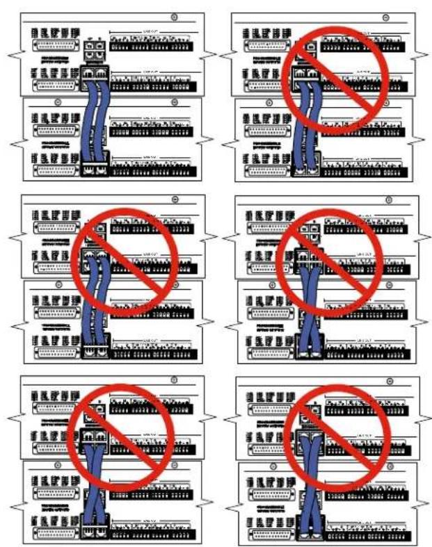
To connect the Master/Slave units, plug one end of a 12 inch Cat5e cable (two are supplied with each with unit) to the transmit (TX) port on the Master unit, and connect the other end to the corresponding receiver (RX) port on the Slave unit immediately below the Master. Repeat this procedure with the second Cat5e cable. (See Expansion Port Digital Audio Network Interface Interconnection Diagram.)
CAUTION: Do not connect these ports to each other on a single unit, and to not cross the cables between the units.
Master/Slave Configuration
When stacking multiple units, one unit is always set as the Master and all subsequent units are set as Slaves. The LCD interface is used to do this.
Expansion Port Digital Audio Network Interface Interconnection Diagram
Crestron® is a registered trademark of Crestron Electronics, Inc. AMX® is a registered trademark of AMX Corp.
Control System Interconnections
In addition to a Windows ^® based computer system, DM processors can be controlled by external serial control system using the RS-232 interface, such as those from Crestron ^® and AMX ^® . ^*
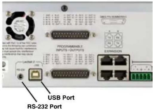
WARNING: Do not use the BLACK cable for Crestron or AMX connections. It is strictly for use with a Windows® based computer system and will NOT work with Crestron or AMX.
Two RS-232 serial cables are provided.
The cable with the BLACK TRS connector is an RS-232 cable wired for use with a laptop computer system.

The cable with the RED TRS connector is designed to be used with a control system such as those from Crestron® or AMX®.

Part# 21529-1 (Black Cable)
Device to PC

Wiring Diagram, 9 Pin D-Sub

flowchart
graph TD
    A["LecNet Port"] --> B["Tip >LecNet Device Transmit"]
    A --> C["Ring >LecNet Device Receive"]
    A --> D["Sleeve >Gnd"]
    B --> E["N/C — CD — 1"]
    B --> F["RX — 2"]
    B --> G["TX — 3"]
    C --> H["DTR — 4"]
    C --> I["Gnd — 5"]
    C --> J["DSR — 6"]
    D --> K["RTS — 7"]
    D --> L["CTS — 8"]
    D --> M["N/C — RI — 9"]
    N["Host Serial Port (PC)"] --> E
    N --> F
    N --> G
    N --> H
    N --> I
    N --> J
    N --> K
    N --> L
    N --> M
Wiring Diagram, 25 Pin D-Sub

flowchart
graph TD
    A["Tip >LecNet Device Transmit"] --> B["RX"]
    C["Ring >LecNet Device Receive"] --> D["TX"]
    E["Sleeve >Gnd"] --> F["Sig Gnd"]
    G["Host Serial Port (PC)"] --> H["Chassis Gnd"]
    I["LecNet Port"] --> J["RTS"]
    I --> K["CTS"]
    I --> L["DSR"]
    I --> M["DTR"]
    B --> N["3"]
    D --> O["2"]
    F --> P["7"]
    H --> Q["1"]
    J --> R["4"]
    K --> S["5"]
    L --> T["6"]
    M --> U["20"]
Part# 21710-1 (Red Cable)
Device to AMX or Crestron


flowchart
graph TD
    A["Tip"] --> B["LecNet Device Transmit"]
    C["Ring"] --> D["LecNet Device Receive"]
    E["Sleeve"] --> F["Gnd"]
    B --> G["N/C"]
    D --> H["TXD"]
    F --> I["Gnd"]
    G --> J["1"]
    H --> K["2"]
    I --> L["3"]
    J --> M["4"]
    K --> N["5"]
    L --> O["6"]
    M --> P["7"]
    N --> Q["8"]
    O --> R["9"]
    P --> S["AMX or Crestron Port"]
Installing LecNet2™ Software and USB Driver
Software Installer - Windows Installation
The example shown her illustrates the installation procedure using a Windows operating system. The screens that appear at each step using another operating system will vary, but the general steps are very similar.
Download the LecNet2/DM Series Support software installer from the web sites under the SUPPORT tab at:
http://www.lectrosonics.com/US
http://www.lectrosonics.com/europe/

- Launch the installer and follow the screen prompts.

- Follow the prompts to run the LecNet2 Setup Wizard.

- The End User License Agreement screen appears. Click on I Agree to continue.
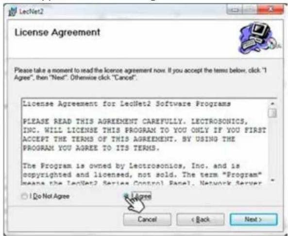
- The installer will automatically download to a folder on your PC, or you can choose which folder it should be stored in.

- Click on Next to complete the installation.
When the installation is complete, the confirmation screen will appear.

USB Driver Installer - Windows Installation
The example shown her illustrates the installation procedure using a Windows operating system. The screens that appear at each step using another operating system will vary, but the general steps are very similar.
Download the LecNet2/DM Series USB drivers from the web sites under the SUPPORT tab at:
http://www.lectrosonics.com/US
http://www.lectrosonics.com/europe/


- Launch the installer and follow the screen prompts.

- Click on Install USB Drivers (The installer will alert you if you choose the wrong bit size.)

- Follow the prompts to run the installer.
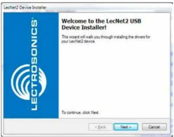
- The End User License Agreement screen appears. Click on I Agree to continue.

- The installer will walk you through installation. When complete, the final screen will appear. Click on Finish to close the installation.

Initial Setup
The initial setup of a DM system is a relatively simple three step process: connect the unit to the computer, turn on the computer and select the appropriate control panel, preset the input, matrix and output. This process assumes that LecNet2™ and, if necessary, the USB driver have been previously installed. If they have not been installed, please refer to Installing LecNet2™ Software and USB Driver.
1) Connect the computer system to the DM unit using either the BLACK DB9 to stereo mini (TRS 1/8") cable for RS-232 communications or the USB cable for USB control. (Both cables are included with the unit.)
Note" Only one DM unit at a time can be connected to the computer system using the RS-232 cable. Multiple units may be connected to the computer system using a USB hub.
2) Turn the computer system on. After the boot sequence is complete, click Start, then All Programs.
3) Select LecNet2, then select the control panel from the list for the DM unit being set up.
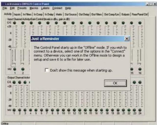
4) If the "Just a Reminder" dialog appears, click OK to continue.
5) Click Connection on the Main Menu bar, then select the type of connection between the computer system or external control system and the DM unit. The choices are:
USB - used when the computer is connected to the DM unit via the front or rear panel USB port.
Network - One or more DM devices may be made available for network connections by connecting them to a gateway server acting as a middleman, receiving commands for a DM over a network connection, and forwarding them to the DM device connected via USB.
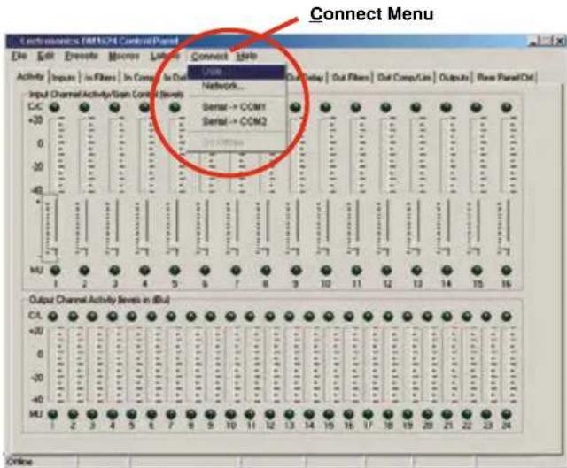
Extron IPL T S - One or more DM devices may be made available for network connections by connecting them to an Extron IPL T S ethernet control interface. The IPL T S interface acts as a middleman, receiving commands for a DM device over a network connection, and forwarding them to the device via an RS232 port. To work as a gateway server the IPL T S interface must be a member of some local area network (LAN) or the Internet, by means of an Ethernet connection.
Serial->COM1 - An RS-232 port for RS-232 communications between the DM and the computer sytsem, or for connecting the DM to an external control system such as those made by Crestron® or AMX®.
Serial->COM2 - Same as above.
Go Offline - No Connection Made, this mode can be used for off line configuration and is the default mode.
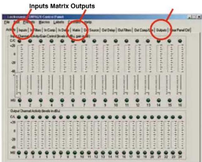
The DM can be configured in the installation or a configuration file can be created off line in advance. The minimum required setup to pass audio includes: Inputs, Matrix and Outputs. Input and output filters, compressors and delays are used to tailor the system for specific audio situations. While these parameters can be set up through the front panel LCD and controls, the Control Panel GUI offers a much more robust and intuitive interface.
Initial Setup Hints
1) The GUI interface is quite intuitive. As a recommended first step, we suggest you select Labels from the Menu Bar and type in all the input and output labels. This will simplify further setup steps because you will be able to easily keep track of which input or output you are adjusting.
2) The right click is powerful in this interface. You can activate quick access to a number of setup functions (for example - right click in any input box in the INPUTS tab). It also allows some powerful cut and paste capabilities - especially in the matrix setup and the filter (both input and output).
3) Store startup settings in a startup default preset. (See Storing and Recalling Presets in the online HELP application.)
4) Presets will take about 4 seconds to switch due to the many parameters in the unit - audio will switch off temporarily during a preset switch to avoid feedback. If you need quicker response with no interruption to the audio, use macros instead - try using the macro recorder for making any changes. The only changes that cannot be made in a macro are filter adjustments, such as EQ.
5) Store presets after changes are made and not before they are made.
6) Help is always available by clicking Help on the Main Menu Bar. This Help is a comprehensive resource and includes the latest revisions to the software and firmware.
IMPORTANT: ANY CHANGES MADE DURING SETUP MUST BE SAVED IN THE UNIT VIA THE PRESET MENU.
Service and Repair
If your system malfunctions, you should attempt to correct or isolate the trouble before concluding that the equipment needs repair. Make sure you have followed the setup procedure and operating instructions. Check the interconnecting cables and then go through the TROUBLESHOOTING section in this manual.
We strongly recommend that you do not try to repair the equipment yourself and do not have the local repair shop attempt anything other than the simplest repair. If the repair is more complicated than a broken wire or loose connection, send the unit to the factory for repair and service. Don't attempt to adjust any controls inside the units. Once set at the factory, the various controls and trimmers do not drift with age or vibration and never require readjustment.
There are no adjustments inside that will make a malfunctioning unit start working.
LECTROSONICS' Service Department is equipped and staffed to quickly repair your equipment. In warranty repairs are made at no charge in accordance with the terms of the warranty. Out-of-warranty repairs are charged at a modest flat rate plus parts and shipping. Since it takes almost as much time and effort to determine what is wrong as it does to make the repair, there is a charge for an exact quotation. We will be happy to quote approximate charges by phone for out-of-warranty repairs.
Returning Units for Repair
For timely service, please follow the steps below:
A. DO NOT return equipment to the factory for repair without first contacting us by letter or by phone. We need to know the nature of the problem, the model number and the serial number of the equipment. We also need a phone number where you can be reached 8 A.M. to 4 P.M. (U.S. Mountain Standard Time).
B. After receiving your request, we will issue you a return authorization number (R.A.). This number will help speed your repair through our receiving and repair departments. The return authorization number must be clearly shown on the outside of the shipping container.
C. Pack the equipment carefully and ship to us, shipping costs prepaid. If necessary, we can provide you with the proper packing materials. UPS is usually the best way to ship the units. Heavy units should be "double-boxed" for safe transport.
D. We also strongly recommend that you insure the equipment, since we cannot be responsible for loss of or damage to equipment that you ship. Of course, we insure the equipment when we ship it back to you.
Mailing address: Shipping address: Telephone:
Lectrosonics, Inc. Lectrosonics, Inc. (505) 892-4501
PO Box 15900 561 Laser Rd., Suite 102 (800) 821-1121 Toll-free
Rio Rancho, NM 87174 Rio Rancho, NM 87124 (505) 892-6243 Fax
USA USA
Web:
www.lectrosonics.com
E-mail (general):
sales@lectrosonics.com
E-mail (service):
service.repair@lectrosonics.com
Mailing address
Lectrosonics Canada
720 Spadina Ave
Suite 600
Toronto, Ontario, M5S 2T9
Telephone:
(877) 753-2876
(416) 596-2202
(416) 596-6648 Fax
E-mail (service):
colinb@lectrosonics.com
joeb@lectrosonics.com
LIMITED ONE YEAR WARRANTY
The equipment is warranted for one year from date of purchase against defects in materials or workmanship provided it was purchased from an authorized dealer. This warranty does not cover equipment which has been abused or damaged by careless handling or shipping. This warranty does not apply to used or demonstrator equipment.
Should any defect develop, Lectrosonics, Inc. will, at our option, repair or replace any defective parts without charge for either parts or labor. If Lectrosonics, Inc. cannot correct the defect in your equipment, it will be replaced at no charge with a similar new item. Lectrosonics, Inc. will pay for the cost of returning your equipment to you.
This warranty applies only to items returned to Lectrosonics, Inc. or an authorized dealer, shipping costs prepaid, within one year from the date of purchase.
This Limited Warranty is governed by the laws of the State of New Mexico. It states the entire liability of Lectrosonics Inc. and the entire remedy of the purchaser for any breach of warranty as outlined above. NEITHER LECTROSONICS, INC. NOR ANYONE INVOLVED IN THE PRODUCTION OR DELIVERY OF THE EQUIPMENT SHALL BE LIABLE FOR ANY INDIRECT, SPECIAL, PUNITIVE, CONSEQUENTIAL, OR INCIDENTAL DAMAGES ARISING OUT OF THE USE OR INABILITY TO USE THIS EQUIPMENT EVEN IF LECTROSONICS, INC. HAS BEEN ADVISED OF THE POSSIBILITY OF SUCH DAMAGES. IN NO EVENT SHALL THE LIABILITY OF LECTROSONICS, INC. EXCEED THE PURCHASE PRICE OF ANY DEFECTIVE EQUIPMENT.
This warranty gives you specific legal rights. You may have additional legal rights which vary from state to state.

- HARDWARE and SOFTWARE INSTALLATION GUIDE
- DM Series
- Digital Audio Processors
- Important Safety Instructions
- Table of Contents
- Introduction
- Unpacking the Unit
- Items Included in the Box:
- Hardware Installation
- Installing the DM System into a Rack
- Cables
- Audio Connections
- Audio Inputs
- Unbalanced Sources
- Balanced Sources
- Phantom Power
- Audio Outputs
- Programmable Inputs
- Programmable Outputs
- Programmable Input/Outputs Connections
- Expansion I/O ports
- Programmable Inputs Wiring Diagram Example
- Master/Slave Configuration
- Expansion Port Digital Audio Network Interface Interconnection Diagram
- Control System Interconnections
- Installing LecNet2™ Software and USB Driver
- Software Installer - Windows Installation
- USB Driver Installer - Windows Installation
- Initial Setup
- Initial Setup Hints
- Service and Repair
- Returning Units for Repair
- LIMITED ONE YEAR WARRANTY
Brand : Lectrosonics
Model : DM812
Category : Hand blender