A-100 - Uncategorized Doepfer - Free user manual and instructions
Find the device manual for free A-100 Doepfer in PDF.


| Product Type | Power Supply & Bus Board for Eurorack Modular Synthesizer |
| Brand | Doepfer |
| Model | A-100SSB |
| Mains Input | 100-240V AC, 50-60 Hz |
| Output Voltages | +12V / -12V / +5V |
| Max Current +12V | 380 mA |
| Max Current -12V | 380 mA |
| Max Current +5V | 50 mA (derived from +12V) |
| Total Current Limit | 380 mA for +12V and +5V combined, 380 mA for -12V |
| Number of Module Connectors | 8 (16-pin pin headers) |
| Bus Signals | +12V, -12V, +5V, GND, CV, Gate |
| Fuse Specification | 800 mA T (time lag) |
| LED Indicators | 3 (for +12V, -12V, +5V) |
| IEC Socket | Yes (mains connector) |
| Mounting Hole Diameter | 3 mm |
| Board Separation | Possible (cut along marked line, connect with wires) |
| Safety Cover | Metal cover on bottom of PCB (mandatory for operation) |
| Protection Features | Safety cover, fuse, overcurrent protection |
| Installation Requirements | Basic electronic knowledge and mechanical skills required; modules must be firmly fixed in a proper case |
| Maintenance | Check LEDs, replace fuse if necessary (only specified value) |
| Compatibility | Doepfer A-100 modules and 100% compatible modules from other manufacturers |
Frequently Asked Questions - A-100 Doepfer
User questions about A-100 Doepfer
0 question about this device. Answer the ones you know or ask your own.
Ask a new question about this device
Download the instructions for your Uncategorized in PDF format for free! Find your manual A-100 - Doepfer and take your electronic device back in hand. On this page are published all the documents necessary for the use of your device. A-100 by Doepfer.
USER MANUAL A-100 Doepfer
A-100SSB Small Supply/Bus
User's Guide

For small DIY set-ups with up to eight modules and a maximum of 380 mA supply current the A-100SSB (small supply/bus board) is intended. A-100SSB is the combination of a small power supply (+12V/max. 380mA, -12V/max. 380mA) and a bus board with 8 connectors for A-100 modules.

For the operation and installation of the A-100SSB basic electronic knowledge and mechanical skills are required. If this does not apply we strictly advice from installing and running the A-100SSB. In this case please return the A-100SSB to the dealer where you purchased it for refund. You have to understand all the information that is included in this document.
The power supply provides the voltages +12V and -12V required to run the A-100 modules. In addition +5V are available which are required for some older A-100 modules and modules from other manufacturers.
The maximum current load is 380 mA for +12V, 380 mA for -12V, and 50 mA for +5 V. If +5V is used the current is taken from the +12V source. In this case the currents for +12V and +5V have to be added and the sum has to be not more than 380mA.
The A-100SSB bus provides connections for up to eight A-100 modules or modules from other manufacturers which are 100% compatible. The busboard also carries the internal signals CV and GATE which may be used if required. This depends upon the installed modules and if they use the internal CV and/or Gate lines (e.g. Midi/USB interfaces, VCOs, ADSRs).
The pc board includes a switching power supply module that converts the incoming mains voltage (110 - 240V AC) into the low voltages (+12VDC, -12VDC) required to run the A-100 modules.
Important safety notes
A-100SSB is equipped with an IEC socket to establish the connection to mains by using a suitable cable. During operation dangerous voltages are present at the bottom of the pc board! For this reason a metal cover is located at the bottom of the pc board which prevents the touching of the dangerous parts of the circuit.
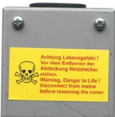
Before the mains connection between the IEC socket and mains is made, it is essential to check if the metal cover is present and firmly mounted! If that does not apply do not connect the A-100SSB to mains and return the unit to the dealer where you purchased it!
Otherwise there is DANGER TO LIFE!
If replacement of the fuse is necessary disconnect A-100SSB from mains and use only the specified fuse value. Never use a higher value!
If the safety check is OK the A-100SSB board has to be mounted at least to a solid base or better to the rear panel of a suitable DIY case. For this purpose several mounting holes with 3 mm diameter are available. Using suitable mounting material (distance bolts or rolls, screws, nuts, washers) the A-100SSB has to be fixed prior to operating the device. Mounting material is not included as the required parts depend upon the case type (wood, plastic, metal) and the thickness.
Any connected modules must be firmly fixed into a proper casing. Any sort of "flying construction" is absolutely discouraged, because if two conductors from separate modules accidentally make contact, (for instance if the bus-bars from one module ended up touching another module's bus-bars), damage will almost certainly result. In cases like that, the guarantee is definitely void.
If required the pc board can be separated into the supply unit and the bus board. For this the board has to be cut (i.e. sawed) along the line that is shown in the Sketch on the next page. The two units have to be linked together by means of four wires which connect the terminals - 12V, GND, +12V and +5V (only if +5V is required) of both parts of the separated pcb. It is possible to solder 6,3mm flat connectors to the corresponding solder points and use suitable cables with female flat connectors to link the two units. Cables or flat connectors are not included.
The separated bus board is mounted as described above. The power supply unit is mounted by means of the two holes of the IEC socket. An additional 3 mm hole is located next to the fuse holder and can be used for additional fixing of the supply board.
Before the separated supply unit is connected to mains once again check if the protecting metal cover is present and firmly mounted!
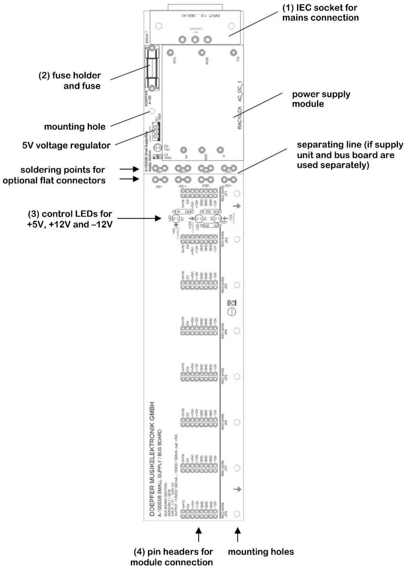
(1) IEC socket
This socket is used to establish the mains connection by means of a suitable cable. The mains cable is not included as the mains connector type is different for each country. A-100SSB has a wide range mains input, i.e. the mains voltage can be in the range 100-240V AC, the frequency can be 50 - 60 Hz.

Once again: Before mains is connected check if the protecting metal cover is present and firmly mounted!
The unit does not have a mains switch. As soon as the mains connection is made A-100SSB is working.
(2) Fuse holder and fuse
If it is necessary to replace the fuse please use only 800 mAT (time lag). Never use a higher value or short the fuse. It may be necessary to replace the fuse when the unit has been overloaded (e.g. by a defective module or a module that has not been connected in the right way to the bus). Before you install a new fuse please remove all modules from the bus to avoid that the fuse blows again.

Disconnect A-100SSB from mains before the fuse is replaced. Use only the specified fuse value. Never use a higher value!
(3) Control LEDs
As soon as the mains connection is made all three control LEDs have to light up! Otherwise something is wrong. If no LED turns on please check the fuse and remove all modules. If only one or two LEDs turn on probably one of the modules causes a short circuit or is not connected in the right way to the bus.
If no LED turns on after the fuse replacement and without any module installed please return the unit to the dealer where you purchased it for checking!
(4) Pin headers for A-100 module connection (JP1 ...JP8)
These are the pin headers which are used to connect the A-100 modules. Up to eight modules can be connected:
- Please calculate the total current requirement of the modules that have to be driven by the A-100SSB
- Check that this total is less than 380 mA for both +12V and -12V rails. Otherwise the A-100SSB is not suitable.
- If +5V is used the current is taken from the +12V source. In this case the currents for +12V and +5V have to be added and the sum has to be not more than 380mA.
- Check if each module is equipped with a ribbon cable with a 16 pin female connector at the open end. The ribbon cable can be 10 or 16 pin but the female connector has to be 16 pin!
- Now join the free end of the ribbon cable to the nearest available position on the bus board
-
For this one has to plug the female 16 pin connector at the free end of the ribbon cable to one of the pin headers of the bus (these are also 16 pins). Use a pin header of the bus board that is close to the position where the module has to be mounted later.
-
Check very carefully that it is connected so that the coloured marking on the ribbon cable is at the bottom of the bus connector. The coloured marking has to align with the "-12V" printing on the bus board next to the pin header. In addition there is a line marked "RED WIRE" on the A-100SSB pc board.
- Check also very carefully that it is pushed fully home, not at a slight angle and not vertically or horizontally displaced.
- Failure to check this may result in the module's and/or supply's instant destruction as soon as the power is turned back on!
- When you're installing extra modules, it may be necessary to take another module or two out, to allow you easier access to the bus board.
- Remove or install modules only during POWER OFF!
Additional information about the modular system A-100 is available on our website www.doepfer.com. Important links are e.g.
www.doepfer.com → Products → A-100 → Technical details
www.doepfer.com → Products → A-100 → Mechanical details
www.doepfer.com → FAQ → A-100 → ....
- A-100SSB Small Supply/Bus
- Important safety notes
- IEC socket
- Once again: Before mains is connected check if the protecting metal cover is present and firmly mounted!
- Fuse holder and fuse
- Disconnect A-100SSB from mains before the fuse is replaced. Use only the specified fuse value. Never use a higher value!
- Control LEDs
- Pin headers for A-100 module connection (JP1 ...JP8)
Brand : Doepfer
Model : A-100
Category : Uncategorized