
UT262E - Measurement Uni-T - Free user manual and instructions
Find the device manual for free UT262E Uni-T in PDF.


| Product Type | Digital Multimeter |
| Brand | Uni-T |
| Model | UT262E |
| Category | Measurement |
| Dimensions (approx.) | 180 x 87 x 47 mm |
| Weight (approx.) | 370 g (with battery) |
| Power Supply | 9V battery (6F22 or NEDA 1604) |
| Display | LCD, 6000 counts with backlight |
| AC Voltage Range | 0.1 mV to 750 V |
| DC Voltage Range | 0.1 mV to 1000 V |
| AC Current Range | 0.1 µA to 10 A |
| DC Current Range | 0.1 µA to 10 A |
| Resistance Range | 0.1 Ω to 60 MΩ |
| Capacitance Range | 1 pF to 60 mF |
| Frequency Range | 10 Hz to 60 MHz |
| Temperature Range | -40°C to 1000°C (with thermocouple) |
| Diode Test | Yes |
| Continuity Test | Yes (audible buzzer) |
| Safety Rating | CAT II 1000V, CAT III 600V |
| Auto Power Off | Yes (15 minutes) |
| Maintenance | Clean with dry cloth, replace battery when low |
| Spare Parts / Reparability | Contact Uni-T service center for replacement parts |
| General Information | Includes test leads, thermocouple, manual, battery |
Frequently Asked Questions - UT262E Uni-T
User questions about UT262E Uni-T
0 question about this device. Answer the ones you know or ask your own.
Ask a new question about this device
Download the instructions for your Measurement in PDF format for free! Find your manual UT262E - Uni-T and take your electronic device back in hand. On this page are published all the documents necessary for the use of your device. UT262E by Uni-T.
USER MANUAL UT262E Uni-T
natural_image
Abstract geometric pattern of gray squares arranged around a central square (no text or symbols)
P/N:110401110460X
UNI-T®

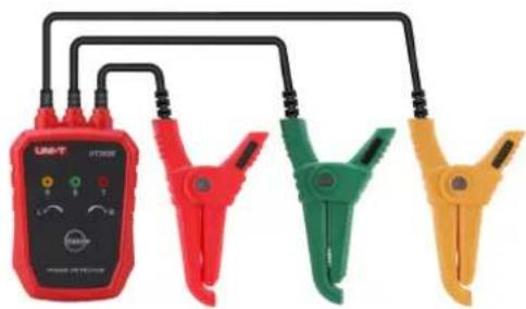
natural_image
Four clamp meters in red, green, yellow, and black connected by black cables (no visible text or symbols)UT262E
Phase Detector
User Manual
Preface
Thank you for purchasing this brand new product. In order to use this product safely and correctly, please read this manual thoroughly, especially the safety notes.
After reading this manual, it is recommended to keep the manual at an easily accessible place, preferably close to the device, for future reference.
Limited Warranty and Liability
Uni-Trend guarantees that the product is free from any defect in material and workmanship within one year from the purchase date. This warranty does not apply to damages caused by accident, negligence, misuse, modification, contamination or improper handling. The dealer shall not be entitled to give any other warranty on behalf of Uni-Trend. If you need warranty service within the warranty period, please contact your seller directly.
Uni-Trend will not be responsible for any special, indirect, incidental or subsequent damage or loss caused by using this device.
Content
Introduction.... 5
Electrical Symbols....6
Technical Specification....7
Corresponding Relation....9
Structure....9
Operating Method....10
Battery Replacement.... 13
Trouble Shooting....14
Packing List.... 15
Warning
Thank you for purchasing our UT262E non-contact Phase Detector, for better use of this product, be sure to:
----To read this manual carefully.
----Comply strictly with safety rules and precautions set out in this manual.
- Pay special attention to safety under any circumstances while using the instrument.
- Take note of the label text and symbols on the panel and back of the instrument.
- Check the instrument, lead wire and clamps, make sure no damage, no exposed and no break.
- Please don't touch an exposed wire in measurement.
- Please don't place and store the instrument at the place with high temperature, humidity, moisture condensation and straight sunlight for a long time.
- Remove the battery if the instrument is not in use for a long time.
- Take not of the polarity when replacing the battery, don't replace batteries before moving away the clamps from wires
- The operation, disassembly and maintenance of the instrument must be carried out by qualified personnel authorized to do so.
-
The instrument should be stopped from being used immediately and sealed if danger is brought up in case of continued use; only a competent body can be authorized to deal with it.
-
If use the detector without following up the operating instructions, the protection provided by the detector may be impaired or lost.
- This product can not be used in an environment containing dangerous uninsulation conductors or conductors with damaged insulation
- “⚠” on the instrument is the warning sign, the contents of this manual must be followed for safe operation.
- “⚠️” in the manual is the danger sign, the contents of this manual must be followed for safe operation.
Introduction
UT262E Non-contact Phase Detector breaks through the traditional methods of phase detection. The traditional method is to connect three exposed clips or probes to three bared live wires, so it needs to disconnect the three wires. While UT262E Non-contact Phase Detector adopts non-contact measurement, no need to disconnect wires, no need to touch high voltage bared live wires. With the three clamps clipped on the insulation layer of three phase live wires, then the phase can be detected, meanwhile sound and light indicates positive and negative states.
UT262E Non-contact Phase Detector also has the functions of live wire examination, power inspection, phase deficiency judgement, breakpoints finding, breakpoints positioning.
UT262E Non-contact Phase Detector is a convenient and fast tool for phase detection, with clear display. It improves the safety of field testing, ensures the safety of operators, increases productivity.
Electrical Symbols
| Extremely dangerous! The operator must strictly abide by the safety rules, otherwise there is a risk of electric shock, resulting bodily injury or fatalities. | |
| Warning! Safety rules must be abided by, otherwise personal injury or equipment damage may be caused. | |
| ~ | Alternate Current (AC) |
| Direct Current (DC) | |
| CAT III | It is applicable to test and measuring circuits connected to the distribution part of the building's low-voltage MAINS installation. |
| CAT IV | It is applicable to test and measuring circuits connected at the source of the building's low-voltage MAINS installation. |
Technical Specification
| Function | Phase detection (positive/negative), power inspection, phase deficiency judgement, breakpoints finding, breakpoints positioning, wire examination. |
| Battery | 2*1.5V AA (R6P) |
| Measurement Range | 70-1000VAC (Three phase), 45Hz~66Hz (sine wave, continuously) |
| Diameter of wires to be clamped | Outer diameter: ø2mm~ø40mm (insulated wire) |
| LED Display | Positive phase sequence: R-S-T lamps light up, synchronized R lamp lights up green, the buzzer sounds intermittently and slowly. |
| Negative phase sequence: R-S-T lamps light up, synchronized L lamp lights up red, the buzzer sounds intermittently and fast. | |
| Line-voltage indication: R-S-T lamps light up | |
| Default phase: R-S-T lamps light off | |
| Open circuit: R-S-T lamps light off | |
| Power-on Indication | Power indicator lamp lights up blue |
| Auto Power Off | The power will be turned off automatically if the instrument remains idle for 5 minutes after the power is turned on. |
| Dimension | 88mm(L)x66mm(W)x30mm(H) |
| Lead Wire Length | 0.6m |
| Weight | 238g (including batteries) |
| Operating Temperature and Humidity | 0°C~50°C; below 85% RH, non-condensing |
| Storage temperature and Humidity | -20°C~60°C; below 90% RH, non-condensing |
| Maximum Measurement Voltage | AC 1000V |
| Dielectric Strength | 5.4kVrms |
| Safety Specifications | CE, UKCA, IP52, EN61010-1: 2010+A1: 2019, EN 61010-2-030:2021+A11:2021, pollution class 2, CAT III 1000V, CAT IV 600V, transient over voltage 8000v, Indoor use |
Corresponding Relation
| A | B | C |
| L1 | L2 | L3 |
| R | S | T |
| U | V | W |
Structure
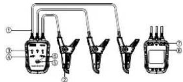
- Lead wire
- Clamps
- R, S, T indicator lamp
- Phase sequence indicator lamp
- Power on indicator lamp
- Power on/off button
- Magnet
- Battery compartment
Operating Method
- Phase sequence detection
Danger! High voltage! Please pay attention to safety!
(1). Clamp three phase wires with the three clamps respectively and arbitrarily.
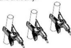
(2). Put the wires at the position marked with “▲” “▼”
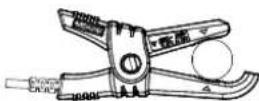
(3). Press "POWER" button, the power indicator lamp lights up blue and the buzzer sounds once. If the lamp cannot light up, maybe the battery is in low power or check the instrument, in that case, please replace the battery or repair the instrument.
(4). If the three phase sequence indicator lamps lights up and R indicator lamp lights up green, and the buzzer sounds intermittently and slowly, so it is positive phase sequence. If the three phase sequence indicator lamps lights up and L indicator lamp lights up red, and the buzzer sounds intermittently and fast, so it is negative phase sequence
(5). Press "POWER" button in power-on state, the power indicator lamp turns off and the buzzer sounds once. The power will be turned off automatically if the instrument remains idle for 5 minutes after the power is turned on, to reduce power consumption.
2. Live wire examination, power inspection, phase deficiency judgement, breakpoints finding
Danger! High voltage! Please pay attention to safety!
(1). Clamp one wire with any one of clamps, if it is an electrified wire (AC 70-1000V), R, S, T lamps light up. In this way to check whether the wire is electrified.
(2). Clamp one wire with any one of clamps, if there is phase deficiency, R, S, T lamps won't light up.
(3). Clamp one wire with any one of clamps and move the clamp along the wire, if R, S, T lamps light off, it means the section wire before this point has a break. Breakpoints can be found out accurately by shortening the range of detection. It is a convenient and safe method for non-contact detection.
Note: This function is very suitable for detecting the circuit fault in the wire, safe and fast!
(4). Clamps and lamps corresponding table:
| Test state | Power-on indication | LED indicator state | Buzzer | |||||
| R | S | T | Positive phase R | Negative phase L | ||||
| Positive phase | ● | ● | ● | ● | ● | ○ | Constant on | Intermittent and slow sound |
| Negative phase | ● | ● | ● | ● | ○ | ● | Constant on | Intermittent and fast sound |
| No phase deficiency (Clip two clamps on the same electrified wire) | ● | ● | ● | ● | ○ | ○ | Flicker | No sound |
| A phase deficiency | ● | ○ | ● | ● | ○ | ○ | Constant on | No sound |
| B phase deficiency | ● | ● | ○ | ● | ○ | ○ | Constant on | No sound |
| C phase deficiency | ● | ● | ● | ○ | ○ | ○ | Constant on | No sound |
Battery Replacement
Pay attention to the battery polarity!
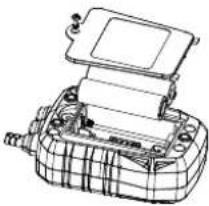
- Make sure the clamps have moved away from wires, don't replace the batteries during measurement.
- Press "POWER" to turn off the instrument.
- Loosen the screw, and then remove the battery cover.
- Replace the batteries with new ones, notice the polarity.
- Put the battery cover back in place, and tighten the screw.
- Press "POWER" to check whether the instrument can be turned on normally, if it cannot be turned on, please check if the battery power is sufficient or repeat step 3.
natural_image
Technical line drawing of a mechanical device with no visible text or symbolsTrouble Shooting
| Symptoms | Possible Causes | Remedies |
| Can't power on (LED power indicator lamp is off, without any display) | No batteries | Set the batteries |
| Wrong battery type | Replace with right type | |
| Insufficient capacity of battery | Replace the batteries | |
| Faulty battery polarity | Install batteries in correct polarity | |
| Poor contact of battery contacts | Replace the battery contacts | |
| Battery cover not completely covered | Cover it again | |
| Defect of circuit component | Repair or replace the PCB | |
| LED dim display | Insufficient capacity of battery | Replace the batteries |
| Incapable of measurement | The three phase wires are not electrified | Not belong to instrument faults |
| Failed to clamp the fine wire | Wind the fine wire around the clamp | |
| Failed to clamp the wire | Refer the manual to clamp again | |
| Lead wire break | Change the lead wire | |
| Defect of circuit component | Repair or replace the PCB |
Packing List
Instrument 1 pcs
Cloth bag 1 pcs
Battery 2 pcs
User manual 1 pcs
UNI-T.
UNI-TREND TECHNOLOGY (CHINA) CO., LTD.
No. 6, Gong Ye Bei 1st Road,
Songshan Lake National High-Tech Industrial
Development Zone, Dongguan City,
Guangdong Province, China
Brand : Uni-T
Model : UT262E
Category : Measurement