
38062 - Camera TORO - Free user manual and instructions
Find the device manual for free 38062 TORO in PDF.


| Product Type | Digital Camera |
| Brand | Toro |
| Model | 38062 |
| Dimensions (approx.) | 10.5 x 6.2 x 3.0 cm |
| Weight (approx.) | 180 g (including batteries) |
| Power Source | 2 x AA batteries (not included) |
| Image Sensor | CMOS, 12 MP (estimated) |
| Optical Zoom | 3x (estimated) |
| Display Screen | 2.7-inch LCD |
| Storage Media | SD/SDHC card (up to 32 GB) |
| Main Functions | Photo capture, video recording, playback, self-timer, flash |
| Cleaning Instructions | Wipe lens with soft, dry cloth; keep camera dry |
| Safety Warnings | Do not expose to water or extreme temperatures; avoid direct eye contact with laser |
| Spare Parts / Repairability | Batteries, charger, USB cable, battery compartment cover (contact Toro support) |
| General Information | User manual available in PDF; designed for everyday photography |
Frequently Asked Questions - 38062 TORO
User questions about 38062 TORO
0 question about this device. Answer the ones you know or ask your own.
Ask a new question about this device
Download the instructions for your Camera in PDF format for free! Find your manual 38062 - TORO and take your electronic device back in hand. On this page are published all the documents necessary for the use of your device. 38062 by TORO.
USER MANUAL 38062 TORO
Table of Contents – Page 1 of 2
AUGER GEARBOX SERVICE
GENERAL INFORMATION
SECONDARY METHOD — TRACTION AND AUGER HOUSINGS SEPARATED:
TORO MODELS 38065 AND 38080
ALL OTHER MODELS
INSTALLATION
AUGER GEARBOX DISASSEMBLY / SERVICE
FAILURE ANALYSIS
GEARBOX ASSEMBLY
BELTS, CONTROLS AND LINKAGES
INTRODUCTION
REPLACING THE AUGER/IMPELLER DRIVE BELT
REPLACING THE TRACTION BELT
REPLACING THE TRACTION BELT
TORO MODELS 38065, 38080, 38085
LAWN-BOY MODELS 28230, 28231
TORO MODELS 38051, 38052, 38054, 38056, 38062, 38063, 38064, 38072, 38073
LAWN-BOY MODEL 28232
TORO MODELS 38053, 38066, 38078, 38083, 38084, 38086
CONTROL AND LINKAGE ADJUSTMENT
AUGER CONTROL ADJUSTMENT — TORO MODELS 38065, 38080, 38085
INSTALL AUGER DRIVE CONTROL ROD
ADJUSTING AUGER/IMPELLER DRIVE BELT
AUGER/IMPELLER DRIVE CONTROL LINKAGE — ALL OTHER MODELS
ADJUSTING TRACTION CONTROL
ADJUSTING THE TRACTION CONTROL
TORO MODELS 38065, 38080, 38085
824XL (TORO MODELS 38066, 38078, 38083, 38084, 38086
LAWN-BOY MODEL 28232
ADJUSTING THE TRACTION ROD
LAWN-BOY MODELS 28230, 28231
TORO MODELS 38051, 38052, 38054, 38056, 38062, 38063, 38064
ADJUSTING THE SPEED SELECTOR
Table of Contents – Page 2 of 2
TRACTION DRIVE SYSTEMS - CONTINUED
DISASSEMBLY
LAWN-BOY MODELS 28230, 23231
TORO MODELS 38051, 38052, 38054, 38056, 38062, 38063, 38064, 38072, 38073
ASSEMBLY
LAWN-BOY MODELS 28230, 23231
TORO MODELS 38051, 38052, 38054, 38056, 38062, 38063, 38064, 38072, 38073
ASSEMBLY TIPS
ASSEMBLY STEPS
DISASSEMBLY
TORO MODELS 38066, 38078, 38083, 38084, 38086
ASSEMBLY
TORO MODELS 38066, 38078, 38083, 38084, 38086
SUB ASSEMBLY REPAIR
TORO MODELS 38066, 38078, 38083, 38084, 38086
TRACTION SHAFT/FRICITION WHEEL DISASSEMBLY
ASSEMBLY
AXLE AND FRICTION PLATE DISASSEMBLY
AXLE AND FRICTION PLATE ASSEMBLY

LAWN-BOY®
2-Stage Snowthrower Drive Systems Service Manual
natural_image
Two black-and-white photos of a small snowman with visible blades and control arms, no text or symbols present.This manual was written expressly for the Toro and Lawn-Boy servicing dealer. The Toro Company has made every effort to make the information in this manual complete and correct.
This manual was written with assumption that the reader has basic mechanical knowledge and skills. This book contains material covering the Toro and Lawn-Boy brand 2-Stage Snowthrowers produced from 1990 to 2002, and may be specified for use on products built before 1990 or after 2002 that are similar in design.
We hope that you find this manual a valuable addition to your service shop. If you have questions or comments regarding this manual, please contact us at the following address:
The Toro Company
Consumer Service Department
8111 Lyndale Avenue South
Bloomington, MN 55420-1196
The Toro Company reserves the right to change product specifications or this manual without notice.
AUGER GEARBOX SERVICE ..... 1-1
GENERAL INFORMATION 1-1
AUGER GEARBOX LUBRICANT ..... 1-1
GEARBOX REMOVAL 1-1
Primary Method — Minimum Disassembly 1-2
Secondary Method — Traction and Auger Housings Separated: Toro Models 38065 and 38080 ....1-4
Secondary Method — Traction and Auger Housings Separated: All Other Models .... 1-5
INSTALLATION 1-6
AUGER GEARBOX DISASSEMBLY / SERVICE ..... 1-7 Failure Analysis ..... 1-9
GEARBOX ASSEMBLY 1-9
BELTS, CONTROLS AND LINKAGES ..... 2-1
INTRODUCTION 2-1
REPLACING THE AUGER/IMPELLER DRIVE BELT 2-1
REPLACING THE TRACTION BELT ..... 2-2 Replacing the Traction Belt — Toro Models 38065, 38080, 38085 ..... 2-2
Replacing the Traction Belt — Lawn-Boy Models 28230, 28231 and Toro Models 38051, 38052, 38054, 38056, 38062, 38063, 38064, 38072, 38073 ... 2-3
Replacing the Traction Belt — Lawn-Boy Model 28232 and Toro Models 38053, 38066, 38078, 38083, 38084, 38086 ..... 2-4
CONTROL AND LINKAGE ADJUSTMENT....2-7
Auger Control Adjustment — Toro Models 38065, 38080, 38085 . . . . 2-7 Install Auger Drive Control Rod . . . . 2-7 Adjusting Auger/Impeller Drive Belt . . 2-7
Auger/Impeller Drive Control Linkage — All Other Models 2-8
ADJUSTING TRACTION CONTROL ..... 2-9
Adjusting the Traction Control — Toro Models 38065, 38080, 38085 ..... 2-9
Adjusting the Traction Control — 824XL (Toro Models 38066, 38078, 38083, 38084, 38086 and Lawn-Boy Model 28232)....2-10
ADJUSTING THE TRACTION ROD — LAWN-BOY MODELS 28230, 28231 AND TORO MODELS 38051, 38052, 38054, 38056, 38062, 38063, 38064 .... 2-11
ADJUSTING THE SPEED SELECTOR ..... 2-12
Axle and Friction Plate Disassembly .... 3-18
Axle and Friction Plate Assembly ..... 3-19
THIS PAGE INTENTIONALLY LEFT BLANK
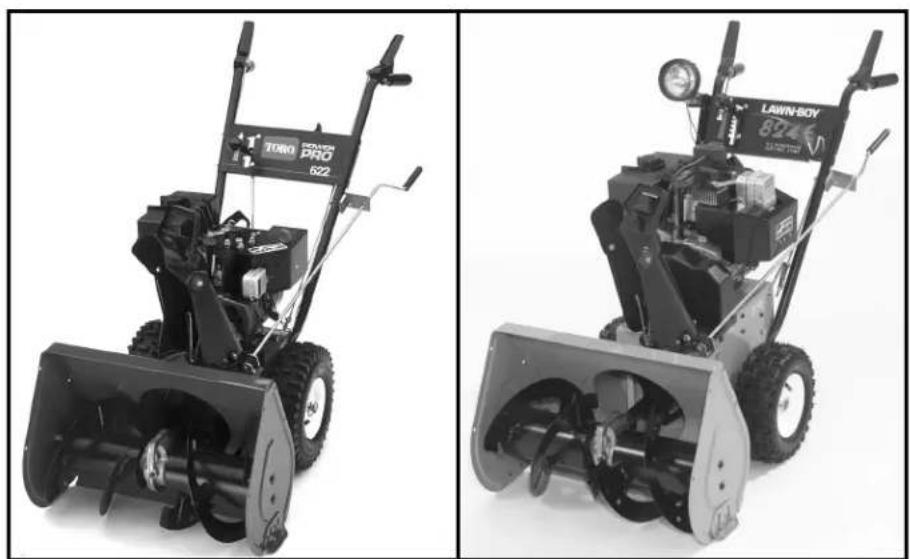
This manual will cover service to the auger and traction drive systems on small and intermediate frame 2 stage snowthrowers. Service information for Power Shift snowthrowers is contained in manual 492-0354.
The models covered are as follows*:
| Model | Model Name | Year | Auger Gearbox Lubricant |
| 28230 522R | 1997-2000 MAG 1 | ||
| 28231 522R | 1997 MAG 1 | ||
| 28232 824E | 1999-2000 MAG 1 | ||
| 38051 522 | 2000-2001 MAG 1 | ||
| 38052 521 | 1990-1996 MAG 1 | ||
| 38053 824 | 2000-2002 MAG 1 | ||
| 38054 521 | 1990-1996 MAG 1 | ||
| 38056 521 | 1990-1991 MAG 1 | ||
| 38056C 521 | 1990 MAG 1 | ||
| 38062 622 | 1997-1999 MAG 1 | ||
| 38063 622 | 1997-2002 MAG 1 | ||
| 38064 622 | 2000-2002 MAG 1 | ||
| 38065 624 | 1990 | 90 wt. | |
| 38066 | 824XL | 2000-2002 | 90 wt. |
| 38072 724 | 1993-2000 MAG 1 | ||
| 38073 724 | 1993-2000 MAG 1 | ||
| 38078 824 | 2000-2002 MAG 1 | ||
| 38080 824 | 1990-1993 | 90 wt. | |
| 38083 | 824XL | 1997-1999 | 90 wt. |
| 38084 | 824XL | 1997-1999 | 90 wt. |
| 38085 824 | 1990 | 90 wt. | |
| 38086 | 824XL | 2000-2002 | 90 wt. |
Model numbers 28XXX are Lawn-Boy.
Model numbers 38XXX are Toro.
Engines: All of the models in the table were
manufactured with engines from the Tecumseh
Products Company. Refer to their service manual for engine information.
Note: Maximum RPM for all models is 3300 ± 150 RPM.
* This manual may be specified for products produced before 1990 or after 2002 in addition to the models above.
THIS PAGE INTENTIONALLY LEFT BLANK
GENERAL INFORMATION
The manual takes a systems approach. There are two versions of the auger gearbox and three versions of the traction drive system used among the various 2-stage models.
For information on the auger drive or linkage adjustments see the section titled Belts, Controls and Linkages.
The lubricant level in a gearbox should be checked prior to each season.
Two different lubricants are used in the various models. They are NOT interchangeable. Use the lubricant specified in the model chart.
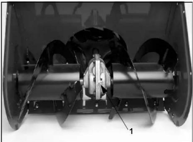
90 wt. indicates a 90-weight gear oil. A multi weight such as 85-120 is acceptable as long as it encompasses the 90 weight. The oil used must also have an extreme pressure (EP) rating of GL5 or higher. Fill until it runs out of the fill check plug (Figure 1).
natural_image
Interior view of a vehicle showing internal components and structural elements (no visible text or symbols)Figure 1
DSC-0168
- Check/fill plug
MAG 1 is a special low temperature grease made by Lubriplate™. Use 1/3 tube of MAG 1 per gearbox. Obtain from your area Lubriplate Distributor or from your Toro parts supplier (Toro Part Number 505-101) (Figure 2).
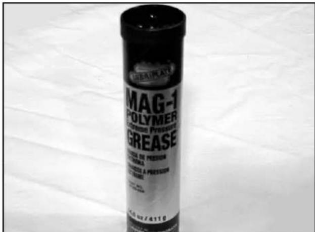
Figure 2
MVC-458
Should you see an oil leak, disassembly is required. Lubriplate MAG 1 is thick so it will normally not leak out even with a failed seal. The bearings used in all applications are oil impregnated, so they do not require regular maintenance. Internal gearbox repair will require removal from the chassis.
GEARBOX REMOVAL
There are two methods commonly used to remove the auger gearbox:
- The primary method is to remove the auger assembly without separating the traction assembly from the auger housing.
- The secondary method is to separate the auger and traction assemblies. Separating the auger and traction assemblies improves access if the auger is difficult to remove.
Primary Method — Minimum Disassembly
The following steps apply to all models.
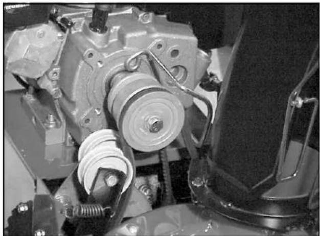
- Remove the belt cover. Loosen the belt guide on the engine crankshaft and remove the auger belt. DO NOT bend the belt guide out of the way (Figure 3).
natural_image
Close-up of mechanical components including a pulley and spring assembly (no visible text or symbols)Figure 3 MVC-526
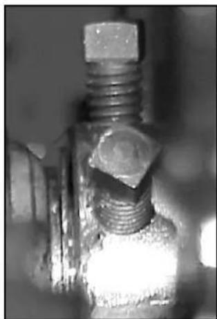
- On the forward side of the auger pulley is 1 or 2 set screws, depending on the model, which must be loosened. Use the square end of a 3/8" socket extension. Note: The pulley is keyed to the shaft and will be removed later (Figure 4).
natural_image
Close-up of a mechanical bolt with threaded end and hexagonal head (no visible text or symbols)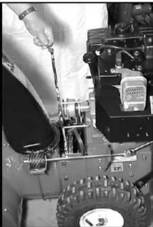
natural_image
Close-up of a person in protective gear working on a small wheeled vehicle engine with visible tire, spring, and battery (no text or symbols)Figure 4 MVC-527/MVC-536
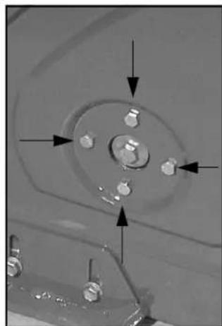
- In the center of each side plate are either two or four cap screws (depending on the model). These go into the bearing that supports each side of the auger. Remove the cap screws (Figure 5).
natural_image
Close-up of a mechanical component with four bolt holes and directional arrows indicating alignment (no text or symbols)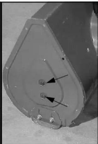
natural_image
Close-up of a metallic mechanical component with internal features and mounting holes (no visible text or symbols)Figure 5 MVC-529/MVC-531
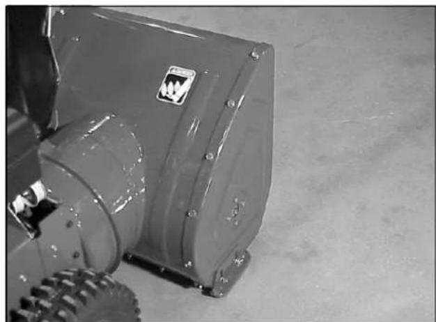
- Many models have side plates that are attached by cap screws and lock nuts. Removing or at least loosening one side plate will ease removal of the auger assembly (Figure 6).
natural_image
Close-up of a mechanical device with visible mounting holes and a label (no readable text or symbols)Figure 6 MVC-530
- Loosen the rear and remove the front capscrew securing the idler arm to the chassis.
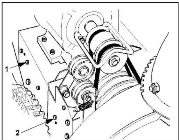
Figure 7
M-3331
-
Loosen
-
Remove
-
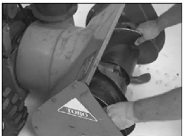
Begin to pull the auger assembly out to the front. Note: The auger pulley and key have not yet been removed. However, if you pull the auger slightly forward, it will make it easier to slide the pulley off the end of the impeller shaft. Once the pulley is out of the way, remove the key (Figure 8 and Figure 9).
natural_image
Close-up of hands operating a large industrial machine component labeled 'TORO' (no visible text or symbols beyond label)Figure 8
2768-022
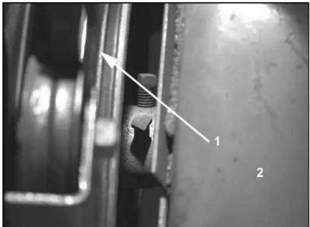
Figure 9
2768-023
-
Pulley
-
Auger housing
-
Model 38065 and 38080 only — Disconnect the (2) scraper springs from either the slot in the side plates or from the scraper. Also there are two bolts, sleeves, and bumpers that limit the scraper travel, one through the side plate on each side, into the scraper. Both must be removed (Figure 10).
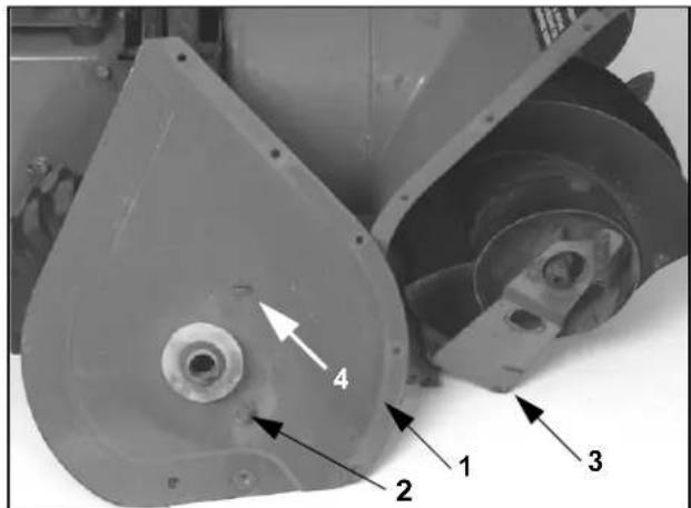
Figure 10
2768-029
-
Side plate
-
Scraper
-
Bumper
-
Spring mount
-
The auger assembly can now be pulled completely from the auger housing.
-
The auger flighting is attached to the auger shaft with one bolt and locknut. Reach through the holes in the drum augers to access. On models without drum augers, the bolts are easily accessible (Figure 11).
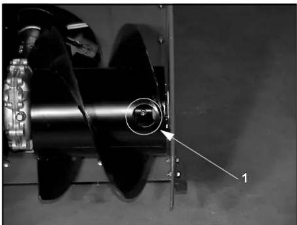
natural_image
Close-up of a mechanical component with a circular inset highlighting a central hole, labeled '1' (no text or symbols on the main subject)Figure 11
MVC-533
1. Access hole
The auger assembly can be separated from the traction assembly. However, it is generally not necessary to work on the auger. Should the auger pulley be rusted on the shaft, it might be easier to remove the pulley with the traction assembly out of the way.
Secondary Method — Traction and Auger Housings Separated: Toro Models 38065 and 38080
- Remove the belt cover. Loosen the belt guide and remove the auger belt (Figure 12).
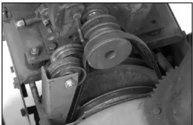
natural_image
Close-up of mechanical components including springs, pulleys, and bolts (no visible text or symbols)Figure 12
2768-021
- Drain the fuel and oil and stand the machine up on its auger. Support or brace to prevent tipping (Figure 13).
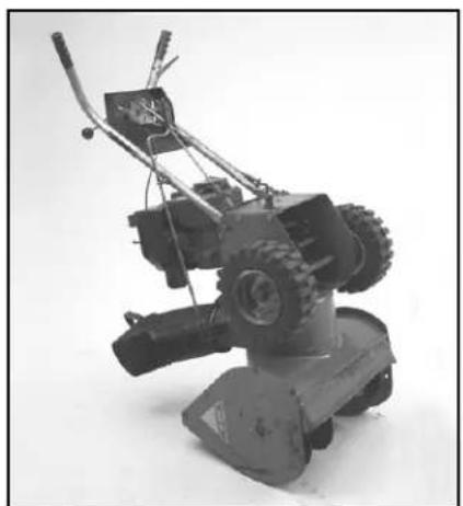
natural_image
Black-and-white photo of a small manual tiller with visible blades and tools (no text or symbols)Figure 13
2768-027
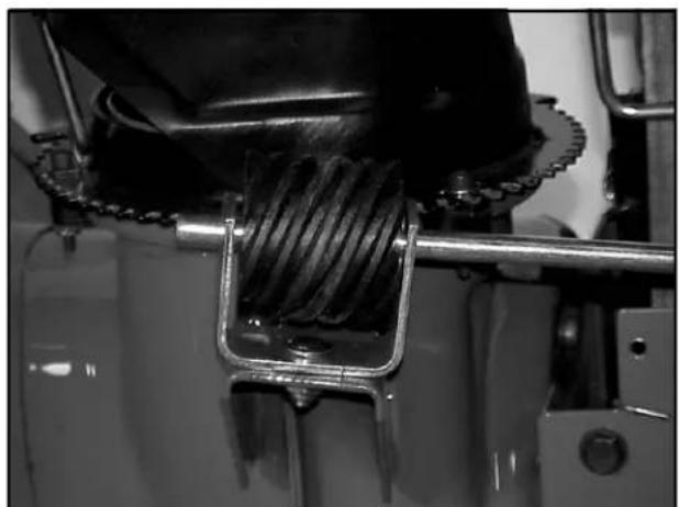
- Disconnect the chute crank rod at the auger (Figure 14).
natural_image
Close-up of a mechanical assembly with a coiled spring and metal frame (no visible text or symbols)Figure 14
MVC-534
- Remove the lower cover from the traction assembly.
1 - 4 Two Stage Snowthrower Drive Systems Manual
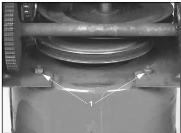
- There are 4 locknuts in the forward part of the housing. These are on studs from the auger. Remove the locknuts. The traction assembly will now lift straight up off the auger assembly (Figure 15).
natural_image
Mechanical assembly with a rotating wheel and flange, showing two white arrows pointing to a component labeled '1' (no text or symbols beyond labels)Figure 15 2768-025
1. Locknut
- Now perform steps 1 - 9 under "GEARBOX REMOVAL" on page 1 - 1.
Secondary Method — Traction and Auger Housings Separated: All Other Models
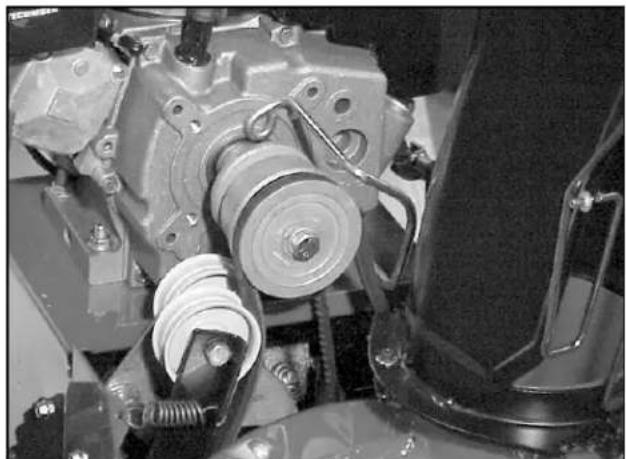
- Remove the belt cover, loosen the belt guide, and remove the traction belt (Figure 16).
natural_image
Close-up of a mechanical assembly with gears and springs (no visible text or symbols)Figure 16 MVC-526
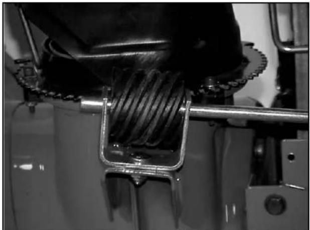
- Disconnect the chute crank rod at the auger (Figure 17).
natural_image
Close-up of a mechanical component with coiled wire and metal frame (no visible text or symbols)Figure 17 MVC-534
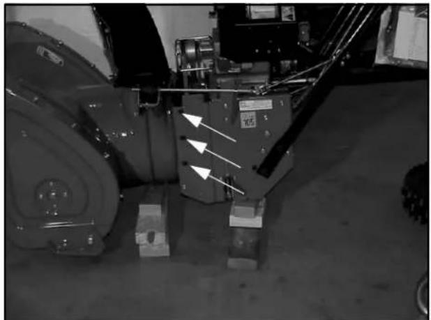
- Place a block of wood under BOTH the auger and traction assembly to support them when the connecting cap screws are removed. Remove the 6 cap screws, 3 on each side, that connect the auger to the traction assembly and separate the two (Figure 18).
natural_image
Close-up of a mechanical assembly with directional arrows indicating motion or force vectors (no readable text or symbols)Figure 18 MVC-535
- Now perform steps 1 - 8 under "GEARBOX REMOVAL" on page 1 - 1.
INSTALLATION
Installation of the auger assembly into the auger housing can be done whether the auger housing and traction assemblies are connected or not. There is no significant time savings to either sequence.
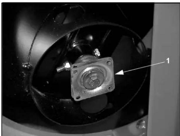
- All self-aligning bearings (sometimes called the flange bearings) MUST be installed loosely. All models have one next to the auger drive pulley and some use 2 more supporting the auger output shafts. In all cases, these bearings must be a little loose to assure the bearing can align itself with the shaft before it is secured (Figure 19).
natural_image
Close-up of a mechanical component with a central square housing and a numbered arrow pointing to it (no visible text or symbols)Figure 19
MVC-540
-
Bearing and flange
-
Make sure all the parts are installed on the auger assembly. All spacers, thrust washers, and auger bearings need to be hanging on the shafts. (Including the scraper for models 38065 and 38080.)
- Slide the assembly into the housing, directing the input shaft into the rear bearing.
- Start the cap screws from the side plates into the bearings that support the auger output shafts. Some models have 2 cap screws into a fixed bearing; others have 4 cap screws into a self-aligning bearing.
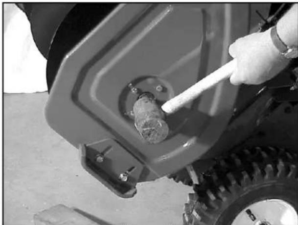
- Models using four bolt bearings ONLY - Strike the side plate and bearing area with a rubber mallet three or four times, then secure the bearings. The jolt aligns the bearings (Figure 20).
natural_image
Close-up of a hand using a tool to adjust or repair a vehicle component, no visible text or symbolsFigure 20
MVC-542
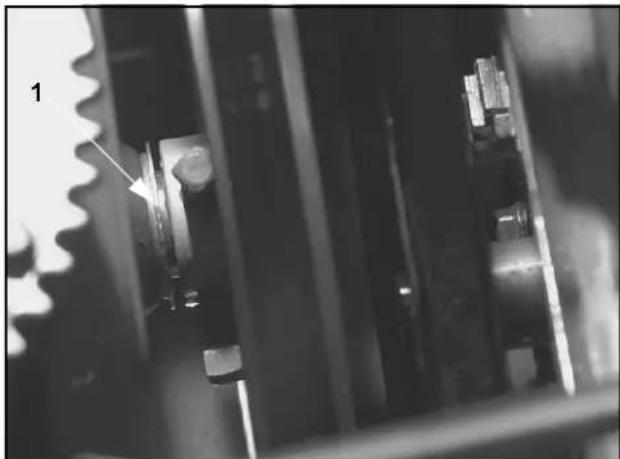
- All models — Rotate the impeller back and forth. One direction will push the impeller shaft to the rear. Rotate it in that direction to force the shaft as far to the rear as possible (Figure 21).
natural_image
Close-up of mechanical gears and shafts in a workshop setting (no visible text or symbols)Figure 21
2773-012
-
Use pulley to remove gap
-
Secure the 4 cap screws on the self-aligning bearing. Install the thrust washer and key.
- Holding the shaft to the rear, install the pulley on the shaft. Push the pulley forward, hold and secure. The pulley is used to limit the front to back movement of the impeller (Figure 21).
AUGER GEARBOX DISASSEMBLY / SERVICE
Once the auger gearbox assembly is removed from the housing the repair process is the same for all models. The only variables are what type of lubricant is used (see the chart on Introduction page 1), whether the impeller is removable from the shaft (on some models the impeller is welded to the shaft) and how the gearbox case halves are sealed.
Auger gearbox disassembly:
- With the gearbox assembly removed from the housing the first step is to slide the bearings off the output shafts. (Model 38080 & 38065, also slide the scraper off).
- All models use a cap screw, lock nut, and spacer to connect the auger to the shaft (Figure 22). Remove the cap screw, nut and spacer and slide both augers from the shaft.
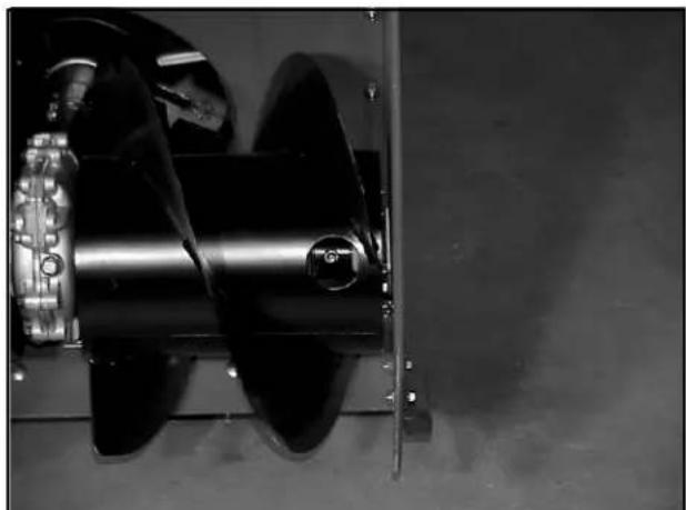
natural_image
Close-up of a mechanical propeller or fan assembly with visible blades and mounting brackets (no text or symbols)Figure 22
MVC-533
- Some models have the impeller welded to the impeller shaft. Others use a combination of bolts, set screws, and a key. If you see bolt(s) through the impeller hub, remove them. Some may have set screws, which only require being loosened. The models with the setscrews also have a key between the hub and shaft. Once the visible retainers are removed, slide the impeller away from the gearbox, the key will be uncovered. Remove the key (Figure 23).
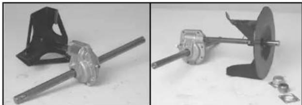
natural_image
Two views of a mechanical assembly: one showing a metal bracket and shaft, the other showing a rotating wheel with mounting flanges and bolts (no text or symbols visible)Figure 23 2773-055/2773-066
- Remove the 8 or 9 self-tapping screws that hold the gearbox halves together. Note: On a model that uses 90 weight gear oil, you may want to place the gearbox over a pan when the screws are removed. Then separate the gearbox halves (Figure 24).
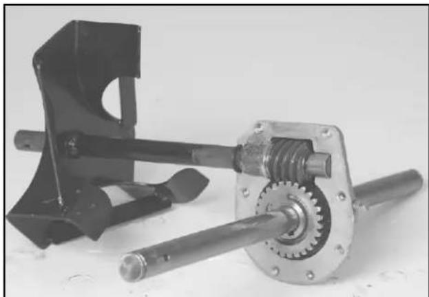
natural_image
Mechanical assembly with a shaft, gear mechanism, and housing component (no visible text or symbols)Figure 24 2773-060
- The impeller shaft can now be removed (Figure 25).
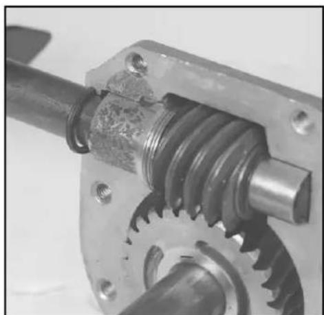
natural_image
Close-up of a mechanical gear assembly with threaded shaft and housing (no visible text or symbols)Figure 25 2773-061
Auger Gearbox Service
-
Clean the output shaft and slide the case halves off. Remove the seals from the case halves and discard the seals.
-
Clean and inspect the bushings in the case halves. If they are damaged or worn, press them out of the case halves at this time.
-
Slide the worm gear off the shaft. Depending on the model, there will be one or two woodruff keys between the gear and the shaft. Refer to the parts manual for your specific machine.
-
Returning to the impeller shaft, the 824XL models have a worm that is actually rolled into the impeller shaft. All other models use an individually replaceable gear. Remove all the bushings, bearings and spacers from the impeller shaft (Figure 26).
-
Now inspect the worm and worm gear. If either gear is damaged, replace them both. When gears run together, they develop wear patterns unique to the two of them. Replacing only one gear will result in early failure.
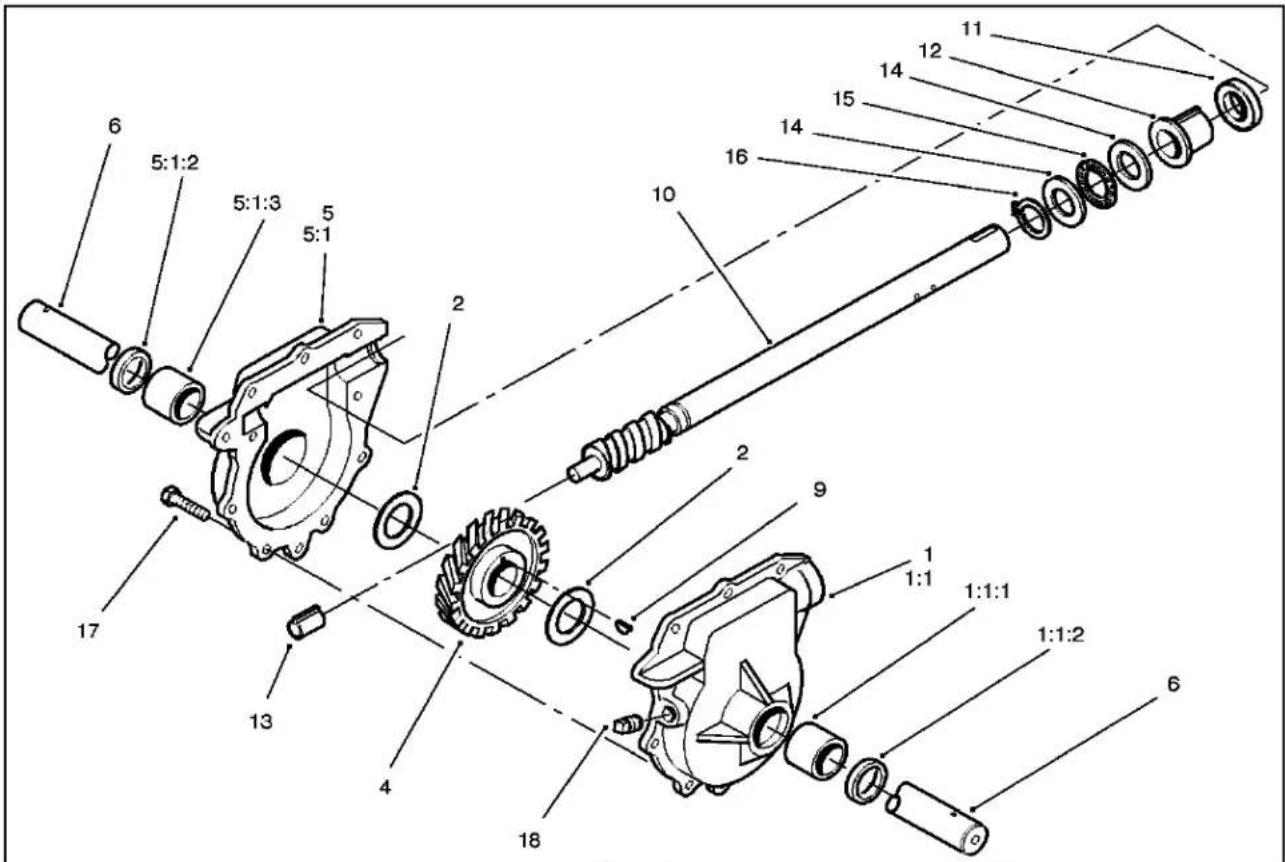
Figure 26
1577-028
- LHauger gearcase ASM
1:1. Auger gearcase ASM, LH
1:1:1. Bushing
1:1:2. Seal-oil - Bearing-thrust
- Gear-helical
- RH auger gearcase ASM
5:1. Auger gearcase ASM, RH
5:1:1. Bushing
5:1:2. Seal-oil
6. Shaft-auger, 24"
9. Key-woodruff
10. Impeller shaft
11. Seal-oil
12 Bushing-input
13. Bushing-worm
14. Washer-thrust
15. Bearing-thrust
16. Ring-retaining, Ext.
17. Screw-HWH
18. Plug-SQH pipe
Failure Analysis
There are some misconceptions regarding these gearboxes that result in incorrectly identifying the causes of failure.
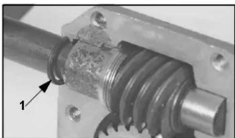
The square cut ring on the impeller shaft is not really a seal. It is a wiper ring that has a tendency to pull down to the shaft when the shaft begins to turn. The bushing next to the ring really deflects most of the oil that is thrown towards that area. The loose fit provides a vent for the case (Figure 27). Occasionally a drop or two of oil will get between the bushing and ring. When the auger drive is disengaged, the ring will relax and that oil might drip into the auger housing. At this rate, the machine can be used for several years without any significant oil loss. The yearly oil level check is more than adequate to compensate for this.
natural_image
Close-up of a mechanical gear assembly with threaded shaft and mounting base (no visible text or symbols)Figure 27
2773-061
- Wiper ring
If there is a significant amount of oil coming out of this area, it would indicate that the gearbox has been at a severe operating angle or the bushing is badly worn.
Oil on the bottom of the gearbox can result from a leak at any part of the case. As there is no internal pressure, any leaking oil runs down the side of the case and collects on the bottom until there is enough to drip off. The source of the oil leak oil can be difficult to see. Sprinkling some powder on the outside of the gearbox will usually show the oil trail. The type of powder used is not important. Just something that will stick to the oil.
When you open a gearbox that has had the gears fail, the remaining oil will likely appear as a small puddle of very thick grease in the bottom. Worm gears normally create a large amount of friction due to the sliding action. When something goes wrong, not enough oil, poor quality oil, a problem with the gears, or just a gear or bearing wearing out, the friction becomes abnormally high. The remaining oil is cooked down to a very thick residue. This can be the result of failures, not the cause.
GEARBOX ASSEMBLY
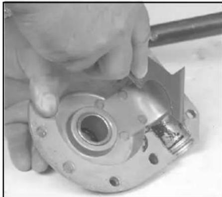
- Use a wire brush or sandpaper to clean the auger shaft. A clean, smooth shaft will help avoid damage when installing new bushings and seals. Clean the old gasket material from the case mating surfaces (Figure 28).
natural_image
Close-up of hands assembling a mechanical component with a cylindrical housing (no visible text or symbols)Figure 28
2773-067
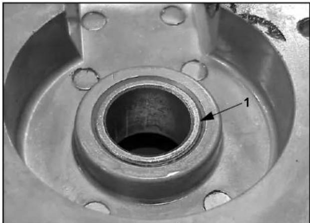
- If new bushings are to be installed in the gear case halves, now is the time. Apply a thin coat of Loctite™ Blue #242 or equivalent to the OUTSIDE of the bushing and press in flush with the INSIDE of the case (Figure 29). This will allow space for the seal on the outside. Wipe up any Loctite™ that is visible. The Loctite™ must not get into the gear or seal area.
natural_image
Close-up of a mechanical component with a central bore and flange, labeled with number 1 (no text or symbols beyond label)Figure 29
MVC-710
- Flush
Auger Gearbox Service
- Insert the keys into the shaft and slide the large worm gear into place. Note: There is a large letter "R" and an arrow on one side of the gear. This gear MUST be installed such that the R and the arrow are on the right hand side and the arrow is pointing forward (Figure 30). This is a two piece gear that is bonded together. If it is installed backwards, the forces try to separate the gear and can result in failure.
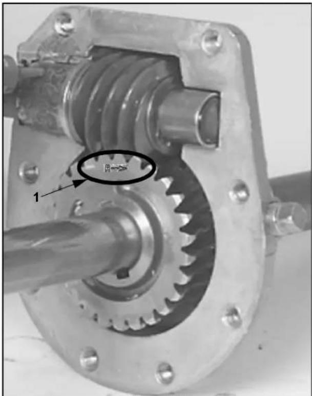
Figure 30
30
-
Letter "R" and arrow
-
Install the thrust washers and slide the case halves on. Note the direction to keep the markings on the gear on the right side.
- There are two versions of the impeller shaft. One has the worm separate and the other has the worm as part of the impeller shaft.
- On models with worm separate from the impeller shaft — Assemble the parts on the impeller shaft. From the inside out, the order is as follows: seal, bushing, thrust washer, thrust bearing, thrust washer, key, worm, thrust washer, retaining ring (sharp edge towards the front) and bushing (Figure 31).
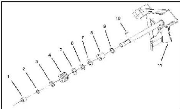
Figure 31
37-6962
- Bushing
- Washer-thrust
- Ring-snap
- Bushing-input
- Washer-thrust
- Ring-quad
- Gear
- Key-woodruff
- Washer-thrust
- Shaft-impeller
- Bearing-thrust
On models with worm integral with the impeller shaft — This version is assembled starting on the end opposite the worm. Start with the snap ring (sharp edge towards the rear), thrust washer, thrust bearing, thrust washer, bushing and seal. There is also a bushing on the worm end of the shaft (Figure 32).
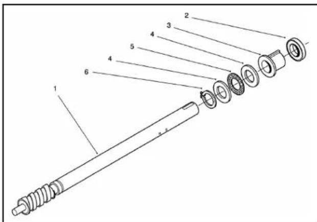
Figure 32
38086-01
- Impeller shaft
- Bushing-thrust
- Seal-oil
- Bearing-thrust
- Bushing-input
-
Ring-snap
-
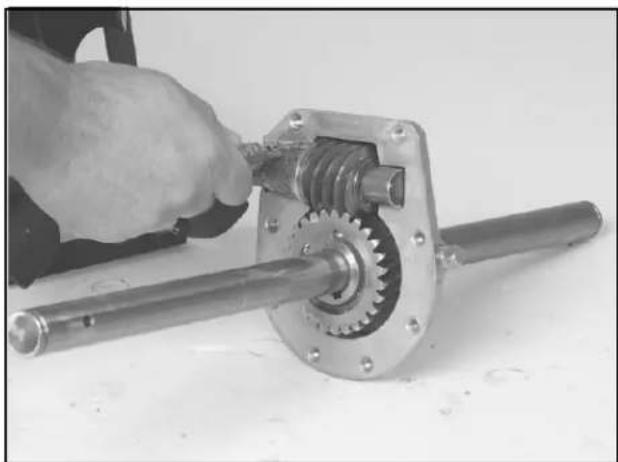
Apply a VERY light coat of Loctite™ Blue #242 or quivalent to the outer diameter of the bearing. Loctite™ should not squeeze out when everything is tightened (Figure 33).
natural_image
Close-up of a hand using a mechanical gear assembly to adjust a shaft (no text or symbols visible)Figure 33 2773-059
-
Some models use a gasket and some do not. For those with a gasket use a small amount of grease to stick the open ends of the gasket in place during assembly. Otherwise this gasket is intended to seal to a clean dry surface.
-
The 824XL seals in a different manner. The mating surfaces must be clean and dry. Then a thin coat of Hylomar (Toro PN 505-129) is applied to BOTH halves. Allow it to cure until it is dull and tacky, 15 minutes or so, then assemble.
-
All models. Apply a light coat of oil or anti-seize to the gear case screws. Tighten them in an X pattern to 120 in/lbs. (15kg/m) (Figure 34).
Note: Some models have 8 gear case screws; others have 9.
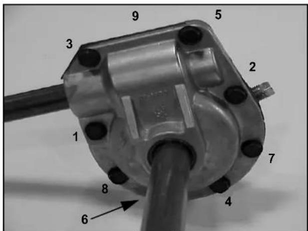
Figure 34 MVC-709
- Fill the gearbox with lubricant. See the chart on Introduction page 1 for the proper lubricant for your model.
THIS PAGE INTENTIONALLY LEFT BLANK
INTRODUCTION
All models use two belts. One to drive the auger and a second to drive the traction system. The auger drive uses a combination idler and brake to engage the belt for driving and to disengage the belt and apply the brake for stopping.
The traction drive uses a constantly tensioned belt. The clutching and shifting are done through the drive plate and friction disc.
REPLACING THE AUGER/IMPELLER DRIVE BELT
When the auger/impeller drive belt becomes worn, stretched, oil-soaked, or otherwise damaged, replace the belt.
- Turn the engine off and disengage all controls.
- Pull the wire off of the spark plug and ensure the wire does not contact the spark plug.
- Remove the two screws that hold the belt cover in place and set the cover aside (Figure 35).
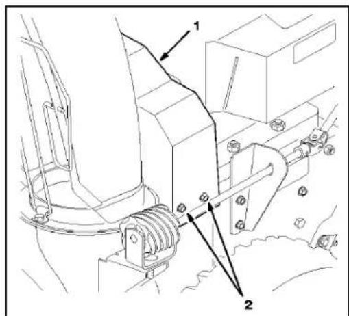
Figure 35
M-2671
-
Upper belt cover 2. Screw (3)
-
Remove the belt guide; do not bend (Figure 36).
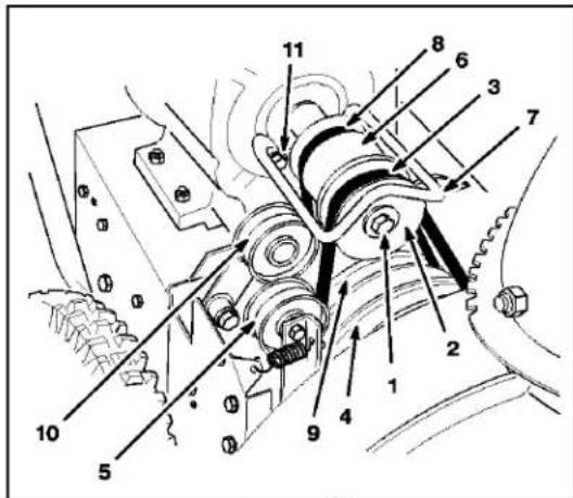
Figure 36
M-3331
-
Engine crankshaft screw, lock washer and washer
-
Idler pulley
-
Engine pulley sheave
-
Center engine pulley
-
Auger/impeller drive belt
-
Belt guide
-
Large auger/impeller pulley
-
Traction belt
-
Traction pulley
-
Traction idler pulley
-
Screw, washer, lock washer
-
Slip the auger belt off the pulleys. Note: On some models (typically the 824 and the 824XL) the auger belt brake will not back off far enough to remove the belt. Remove the front screws and loosen the rear screw that fastens the brake arm assembly to the chassis (Figure 37).
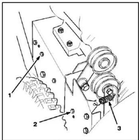
Figure 37
M-2678
-
Rear screw
-
Idler pulley spring
-
Front screw
-
Slip the new belt over the pulleys. Install any parts that were removed.
-
The belt guide must be checked and adjusted. With the engine off, engage both the auger and traction controls. Adjust the belt guide so that there is approximately 1/8 inch (.3 cm) clearance between the belt guide and the belt.
Check auger belt adjustment. See "CONTROL AND LINKAGE ADJUSTMENT" on page 2 - 7 for the linkage adjustment procedures.
REPLACING THE TRACTION BELT
The models covered in this manual use three different methods of tensioning the traction belt. As the tensioning method affects the belt replacement process, they are separated by model number.
Replacing the Traction Belt — Toro Models 38065, 38080, 38085
When traction drive belt (Figure 38) becomes worn, stretched, oil-soaked, or otherwise damaged, replace the belt.
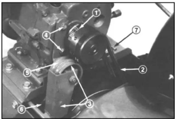
Figure 38
13299-32
- Traction drive belt
- Auger/impeller drive belt
-
Auger/impeller pulley and idler
-
Capscrews, traction idler
- Traction idler pulley
- Traction pulley
-
Belt guide
-
Pull high tension wire off spark plug and make sure it does not contact the plug accidentally.
-
Remove two thread forming screws holding belt cover in place, and set belt guard aside.
-
Move auger drive control to DISENGAGE and wheel drive control to N, neutral. Next, remove auger drive belt from engine pulley and large auger/impeller pulley.
- Loosen two capscrews (securing traction idler arm to front of engine. Next, remove traction drive belt from engine pulley and large traction pulley.
- Install new belt around large traction pulley. Next, loop belt over engine pulley, making sure that belt is on inside of traction idler pulley and wire belt guide.
- Reinstall auger belt around large auger/impeller pulley. Next, loop belt over engine pulley, making sure that belt is on inside of auger/impeller, idler pulley and wire belt retainer. Slide idler arm and pulley assembly against belt to remove belt slack and tighten capscrews.
Note: Tension belt only enough to remove slack. Do not over-tension.
- With the engine off, engage the auger lever. Adjust the belt guide so it is within 1/8 inch (.3 cm) of the belt.
- Install belt cover with two thread forming screws.
- Install high tension lead and test operate unit to check traction. If little or no traction is evident, proceed to step 10. If traction operation is satisfactory, proceed to operate machine.
- Remove high tension lead from spark plug and remove belt guard. Loosen two capscrews securing traction idler arm and slide idler arm and pulley assembly further against belt. Move assembly a minimal amount to assure belt is not over tensioned.
Replacing the Traction Belt — Lawn-Boy Models 28230, 28231 and Toro Models 38051, 38052, 38054, 38056, 38062, 38063, 38064, 38072, 38073
When the traction drive belt becomes worn, stretched, oil-soaked, or otherwise damaged, replace the belt.
- Pull the wire off of the spark plug and ensure that the wire does not contact the plug.
- Drain the gasoline from fuel tank.
- Remove the two screws that hold the belt cover in place and set the cover aside (Figure 39).
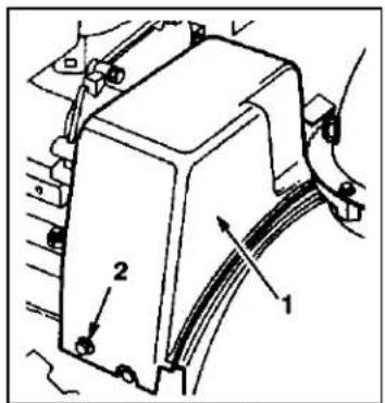
Figure 39
1. Belt cover
2. Screw (2)
661
- Remove the auger/impeller drive belt from the engine pulley and the large auger/impeller pulley (Figure 40).
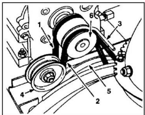
Figure 40
- Traction drive belt
- Auger/impeller drive belt
-
Belt guide
-
Idler pulley
- Large auger/impeller pulley
-
Engine pulley
-
Tip the snowthrower forward and block it so it cannot fall.
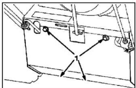
- Remove the four screws that secure the bottom cover to the frame and remove the cover (Figure 41).
natural_image
Technical line drawing of a mechanical assembly with arrows indicating motion or force directions (no text or symbols)Figure 41
1. Screws
M-2592
- Disconnect the spring from the notch in the bottom edge of the side plate (Figure 42).
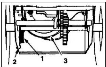
Figure 42
- Spring
-
Notch in side plate
-
Large traction
pulley
650

CAUTION

POTENTIAL HAZARD: The spring is under heavy tension.
WHAT CAN HAPPEN: The spring could be thrown in operator's or bystander's direction.
HOW TO AVOID THE HAZARD: Use caution when removing the spring.
- Set the snowthrower upright.
- Loosen the belt guide (Figure 40).
-
Remove the traction drive belt from the engine pulley and the large traction pulley (Figure 40).
-
Install a new belt around the large traction pulley.
- Loop the belt over the engine pulley, ensuring that the belt is on the inside of the belt guide (Figure 40).
- Tip the snowthrower forward and block it so that it cannot fall.
- Hook the spring into the notch in the bottom edge of the side plate (Figure 42).
- Replace the bottom cover with the four screws.
- Set the snowthrower upright.
- Install the auger/impeller drive belt around the large auger/impeller pulley and engine pulley, ensuring that the belt is on the inside of the idler pulley and belt guide (Figure 40).
- Adjust the belt guide so that there is 1/8 in. (0.3 cm) of clearance between the belt and the guide, and secure the belt guide.
- Install the belt cover.
Replacing the Traction Belt — Lawn-Boy Model 28232 and Toro Models 38053, 38066, 38078, 38083, 38084, 38086
When traction belt (Figure 43) becomes worn, oil-soaked or otherwise damaged, belt replacement is required.
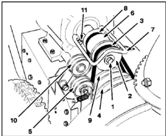
Figure 43
M-3331
- Engine crankshaft screw, lock washer and washer
- Engine pulley sheave
- Auger/impeller drive belt
-
Large auger/impeller pulley
-
Idler pulley
- Center engine pulley
- Belt guide
- Traction belt
- Traction pulley
- Traction idler pulley
-
Screw, washer, lock washer
-
Pull wire off spark plug and make sure it does not contact the plug accidentally.
- Remove (3) screws holding belt cover in place and set cover aside (Figure 44).
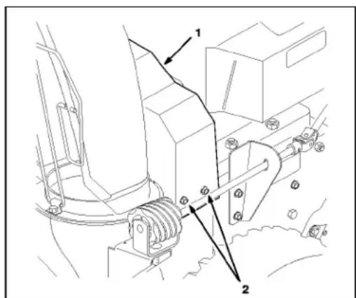
Figure 44
M-2671
-
Upper belt cover
-
Screw (3)
-
Loosen auger brake arm assembly by loosening rear screw and removing front screw (Figure 45).
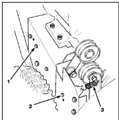
Figure 45
M-2678
-
Rear screw
-
Idler pulley spring
-
Front screw
-
Remove idler pulley spring (Figure 45). Let brake arm assembly hang free but out of the way.
- Remove (2) screws, (2) washers, and (2) lock washers securing belt guide (Figure 43). If the belt will not slip off, the engine pulley can be removed.
- Remove engine crankshaft screw, lock washer and washer (Figure 43).
- Separate and remove engine pulley sheaves (Figure 43).
- Remove auger/impeller drive belt from center engine pulley, leaving belt looped around large auger/impeller pulley. Remove center engine pulley (Figure 43).
- Remove traction belt from traction pulley and engine crankshaft (Figure 43).
- Pull traction idler pulley outward and install new traction belt (Figure 43).
- Reinstall center engine pulley.
-
Pull idler pulley outward and loop auger/impeller drive belt in front of center engine pulley, making sure that belt is on inside of idler pulley and belt guide (Figure 43).
-
Reinstall engine pulley sheave, washer, lock washer, and crankshaft screw. Make sure the indexing rib in the engine pulley sheave is aligned with the indexing notch in the center engine pulley (Figure 46).
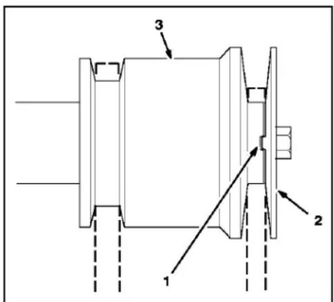
Figure 46
M-2677
-
Indexing rib in indexing notch
-
Engine pulley sheave
-
Center engine pulley
-
Make sure brake pad is properly installed on brake arm. Angled cut-off on brake pad must be positioned as shown in Figure 47.
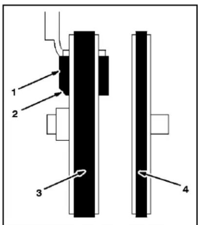
Figure 47
M-2681
View from left side of unit
- Brake pad
-
Angled cut-off
-
Auger/impeller drive
belt -
Traction drive belt
-
Reinstall (2) screws that secure auger brake arm assembly. Make sure tabs fit into holes in left side of machine (Figure 48).
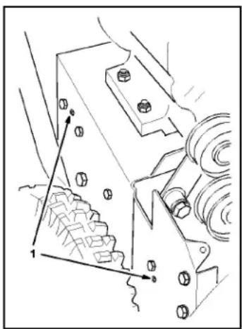
natural_image
Technical line drawing of a mechanical assembly with bolts and rollers (no text or symbols)Figure 48
M-2678
-
Tabs in holes
-
While someone squeezes the auger/impeller control lever (Figure 49) against the handgrip, reinstall belt guide using (2) screws, (2) washers, and (2) lock washers removed previously. Check and readjust belt guide, making sure it does not contact any part of the engine pulley.
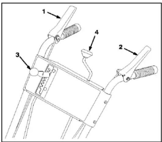
Figure 49
M-4035
-
Auger/impeller control lever
-
Speed selector
-
Traction control lever
-
Discharge chute control
-
Check and adjust auger drive linkage. Refer to steps 5–7 of "Auger/Impeller Drive Control Linkage — All Other Models" on page 2 - 8.
-
Reinstall idler pulley spring.
-
Reinstall belt cover with (3) screws.
-
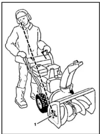
Make sure that auger and impeller are not rotating when auger/impeller control lever is disengaged. While standing in the operator position behind the handles, look around to the side of the auger housing. If the auger and impeller are rotating, a large screw head on the side of the auger housing will be rotating (Figure 50). If the auger and impeller are rotating when the engine is running and the auger/impeller control lever is not engaged, immediately stop the unit. Refer to "Adjusting Auger/Impeller Drive Belt" on page 2 - 7.
IMPORTANT: Do not operate unit if auger and impeller rotate when auger/impeller control lever is not engaged.
natural_image
Illustration of a person using a manual power tool to blade a small turbine (no text or symbols present)Figure 50
1. Large screw head
M-2680
CONTROL AND LINKAGE ADJUSTMENT
Note: Before making any control adjustments, verify that the handles are secured to the traction frame. If the handles move at all, the linkages will not maintain adjustment.
Auger Control Adjustment — Toro Models 38065, 38080, 38085
Install Auger Drive Control Rod
- Move auger drive control backward to DISENGAGE and hold it in that position.
- Rotate clevis at end of auger drive control rod until holes in clevis line up with hole in bent rod (Figure 51). Next, secure clevis and bent rod together with clevis pin and cotter pin.
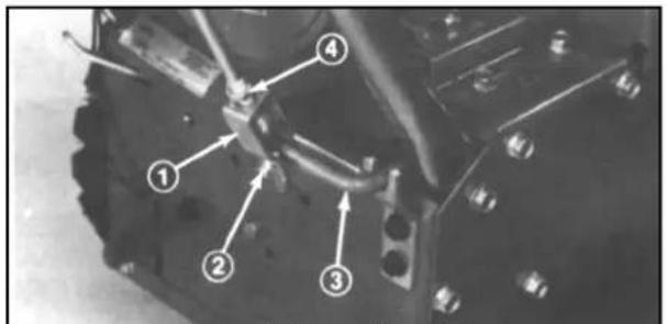
Figure 51
13299-4
-
Clevis
-
Bent rod
-
Clevis pin and cotter pin
-
Jam nut
-
Tighten the jam nut firmly against top of clevis.
Note: Move auger drive control forward to ENGAGE. If excessive force is required to move the control, adjust the auger drive control: refer to Adjusting Auger/Impeller Drive Belt (below).
Adjusting Auger/Impeller Drive Belt
If auger slips, which means the auger drive belt is slipping, an adjustment is required. When a new auger/impeller drive belt is installed, an adjustment may also be required.
- Loosen jam nut from clevis at bottom of auger drive control rod (Figure 52). Next, remove cotter pin and clevis pin holding clevis to bent rod.
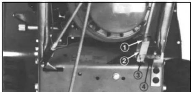
Figure 52
13299-33
-
Jam nut
-
Clevis pin and cotter pin
-
Clevis
-
Bent rod
-
Rotate clevis counterclockwise — out — to increase belt tension. By contrast, rotate clevis clockwise — in — to decrease belt tension.
- Connect clevis to bent rod with clevis pin and cotter pin. Next, tighten jam nut against top of clevis.
- Check tension of belt by operating the auger. If belt still slips, or if the auger does not stop when disengaged, adjust clevis again.
IMPORTANT: Do not adjust belt too tight because the belt will wear out quickly or possibly cause damage to the snowthrower.
Auger/Impeller Drive Control Linkage — All Other Models
There are two adjustment mechanisms used. One has a clevis with a jam nut. The other has a rod going through a loop with a flange nut on either side.
- Thread a hex flange nut (flange side down) onto upper control rod located on right handle (Figure 53).
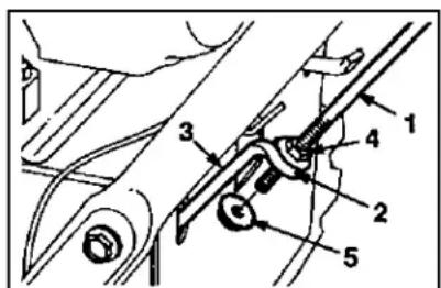
Figure 53
654
1.raction rod
-
Hange nut
-
Loop
-
Locking flange nut
-
Lower traction rod
-
Install lower link through outer hole in lower control rod.
- Insert upper control rod through loop in lower link control rod.
- Thread a flange lock nut (flange side up) onto bottom of upper control rod below loop in lower link.
- Check the distance between the top of the handgrip and the bottom of the auger/impeller control lever (Figure 54). This is a preliminary setting only.
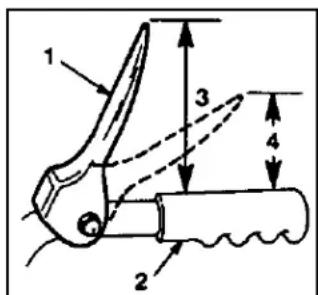
Figure 54
665
- Iraction control
lever
-
4 3/8 m. (11 cm)
-
1 to 2 in. (2.5 to
-
Handgrip
5 cm)
- Remove the belt cover (refer to "REPLACING THE AUGER/IMPELLER DRIVE BELT", page 2 - 1, steps 1-2). Compress the auger/impeller control lever and check that the slack is removed from the auger drive belt when the lever is 1-2 inches (2.5-5 cm) above the handgrip (Figure 54).
- Adjust the clevis or two flange nuts to obtain this dimension, then tighten the two nuts or jam nut securely (Figure 55).
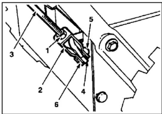
Figure 55
649
-
Jam nut
-
Lower control rod
-
Clevis
-
Clevis pin
-
Upper control rod
-
Cotter pin
-
The auger must stop when the handgrip is released. If it does not stop, adjust the clevis or flange units on the auger rod.
2 - 8 Two Stage Snowthrower Drive Systems Manual
ADJUSTING TRACTION CONTROL
Adjusting the Traction Control — Toro Models 38065, 38080, 38085
- Move wheel drive control into No. 1, 1st gear. Position control lever so its front surface is 1/4 of an inch (6mm) from bottom of slot (Figure 56); then hold lever in this position.
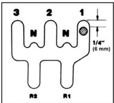
Figure 56
13299-5
- While holding wheel drive control lever in position, push up on long rod and rotate clevis until holes in clevis line up with hole in link arm (Figure 57). Next, secure clevis and link arm together with clevis pin and cotter pin (Figure 57).
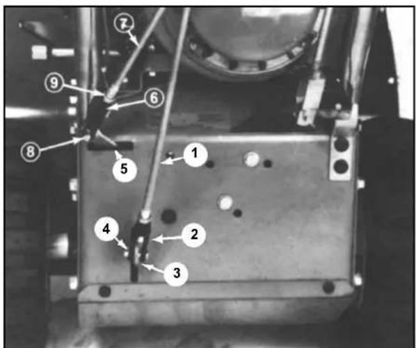
Figure 57
13299-6
-
Long rod
-
Clevis
-
Clevis
-
Short rod
-
Link arm
-
Clevis pin and cotter pin
-
Clevis pin and cotter pin
-
Jam nut
-
Shift arm
-
Move wheel drive control lever onto the hump between N and 1 (Figure 58). Hold wheel drive control lever in this position — on hump.
Note: Lever must be held against the hump, not in the N or 1 position.
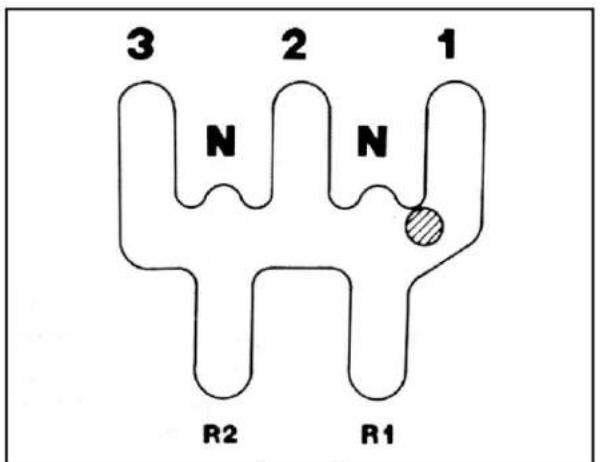
Figure 58
13299-7
-
Move shift arm fully to the left (Figure 57). Next, rotate clevis at end of short rod until holes in clevis line up with hole in shift arm (Figure 57). Secure clevis and shift arm together with clevis pin and cotter pin (Figure 57).
-
Tighten the jam nut against top of both clevises (Figure 57).
Adjusting the Traction Control — 824XL (Toro Models 38066, 38078, 38083, 38084, 38086 and Lawn-Boy Model 28232)
- Slide spring onto bottom of traction control rod (Figure 59).
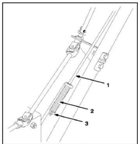
Figure 59
M-2665
-
Iraction control rod
-
Hange locknut
-
Spring
-
Thread a flange lock nut (flange side up) onto bottom of traction control rod below spring.
- Adjust flange locknut up or down on traction control rod until the distance between the top of the handgrip and the bottom of the traction control lever (Figure 60) is approximately five inches (13 cm) (Figure 61). This is a preliminary setting only.
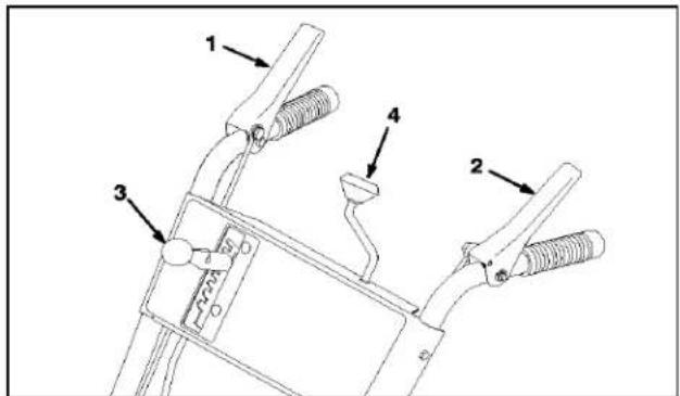
Figure 60
M-4035
-
Auger/impelier control lever
-
Speed selector
-
Discharge chute control
-
Traction control lever
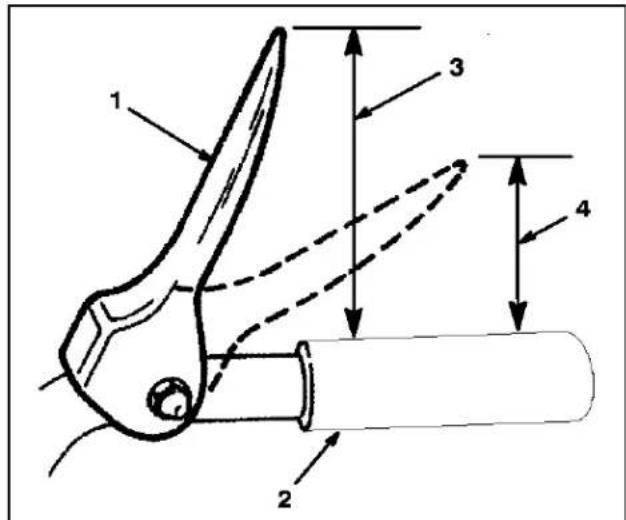
Figure 61
M-2628
-
Iraction control lever
-
Approximately
-
Handgrip
5 inches (13 cm)
-
3-4 inches (8-10 cm)
-
Move speed selector (Figure 60) into fifth gear.
- Slowly pull machine backward while slowly depressing traction control lever toward handle. Adjustment is correct when wheels stop turning and the distance between the top of the handgrip and the bottom of the traction control lever is three to four inches (Figure 61). Readjust flange locknut, if necessary, to obtain this dimension and then tighten flange locknut securely.
ADJUSTING THE TRACTION ROD — LAWN-BOY MODELS 28230, 28231 AND TORO MODELS 38051, 38052, 38054, 38056, 38062, 38063, 38064
- Thread the locking flange nut (flange side up) onto the bottom of the traction control rod, below the loop in the lower traction rod (Figure 62).
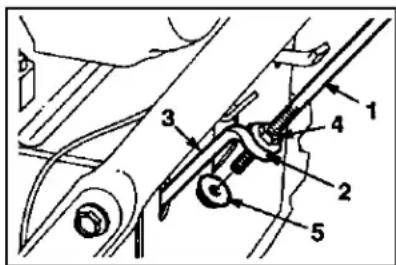
Figure 62
654
- Iraction rod
- Hange nut
- Loop
- Locking flange nut
-
Lower traction rod
-
Adjust the two flange nuts up or down on the traction control rod until the distance between the top of the handgrip and the bottom of the traction control lever (Figure 63) is approximately 4-3/8 in. (11 cm).
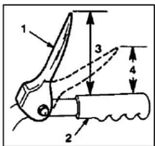
Figure 63
665
-
Iraction control lever
-
4 3/8 in. (11 cm)
-
Handgrip
-
1-2 in. (2.5-5 cm)
-
Tighten the two flange nuts finger tight.
- Move the speed selector (Figure 64) into third gear.
Note: If the speed selector does not move into third gear, adjust the speed selector before continuing. See "ADJUSTING THE SPEED SELECTOR" on page 2 - 12.
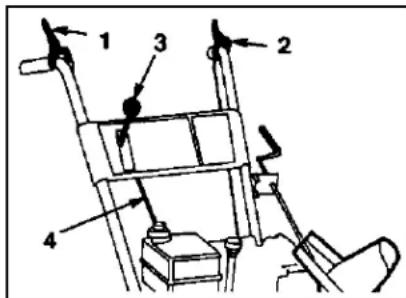
Figure 64
879
- Auger/impeller control lever
- Speed selector
- Speed selector rod
-
Traction control lever
-
Slowly pull the snowthrower backward while slowly pressing the traction control lever toward the handle. The adjustment is correct when the wheels stop rolling backwards and the distance between the top of the handgrip and the bottom of the traction control lever is one to two inches (2.5 to 5 cm) (Figure 63).
-
Adjust the two flange nuts, if necessary, to obtain this dimension.
- Tighten the flange nuts securely.
ADJUSTING THE SPEED SELECTOR
If the snowthrower is slow, the No.1 speed selection has no speed, or the speed selector does not move into the No. 3 speed selection, adjust the speed selector linkage.
- Disconnect the wire from the spark plug and make sure that the wire does not contact the spark plug.
- Tip the snowthrower forward and block it so that it cannot fall.
- Remove the four screws that secure the bottom cover to the frame and remove the cover.
- Loosen the flange nuts that secure the selector plate to the control panel (Figure 65).
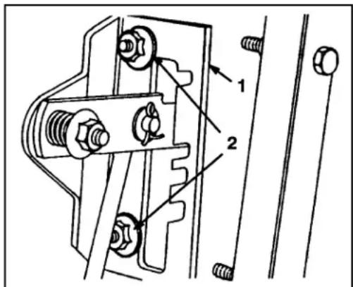
Figure 65
1. Speed selector plate 2. Hange nuts
- Shift the speed selector to third gear and push down on the speed selector plate to move the drive assembly to the right.
Note: The drive assembly should be 1/8 inch (3mm) from the roll pin; if not, slide the selector plate (Figure 65) until the gap is 1/8 inch (3mm) (Figure 66).
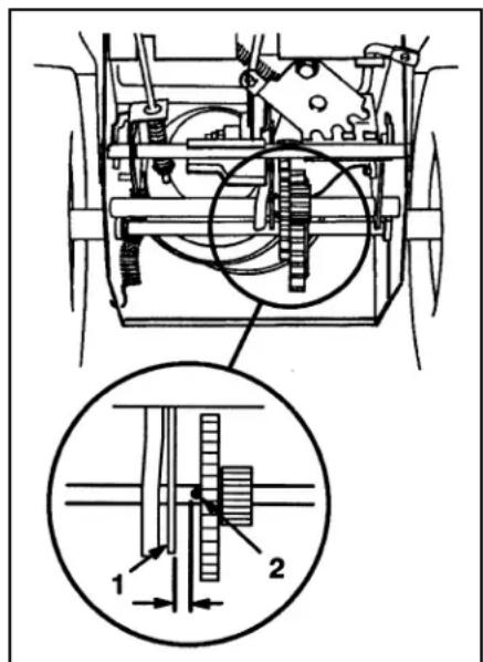
Figure 66
1. Rdl pin 2. Drive assembly
650/913
- With the drive assembly 1/8 inch (3mm) from the roll pin, tighten the flange nuts that secure the speed selector plate.
- Shift the speed selector to the R (Reverse) position and back to third gear to check the adjustment.
- If the space between the roll pin and the drive assembly is more than 3/16 inch (5 mm), repeat steps 4 through 7.
- Install the bottom cover and return the snowthrower to the upright position.
INTRODUCTION
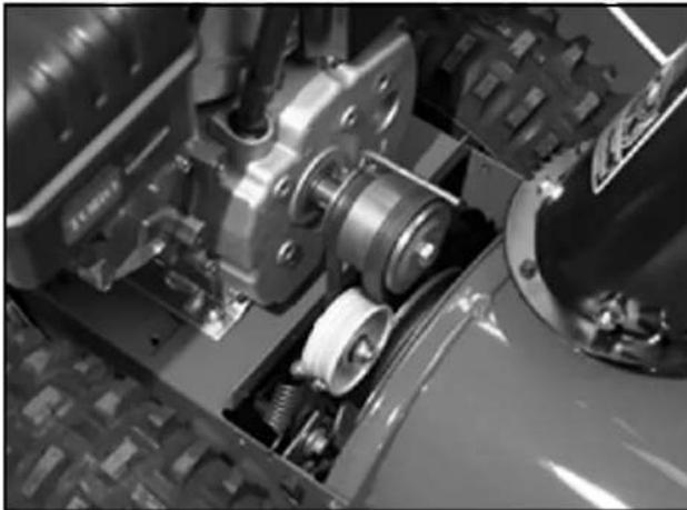
All models use some variation of a friction drive. The engine drives a belt, which causes a drive plate(s) to rotate. As this belt is constantly tensioned, the belt and drive plate turn whenever the engine is running (Figure 67).
natural_image
Close-up of a mechanical assembly with gears and springs (no visible text or symbols)Figure 67
2773-014
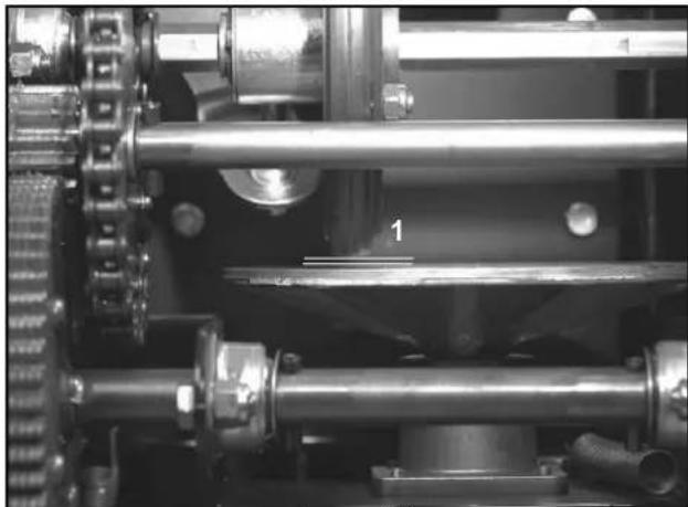
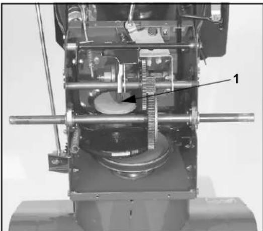
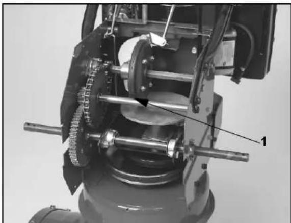
Clutching and speed control is accomplished by moving the friction wheel. When declutched the friction wheel is not contacting the drive plate (Figure 68). When the drive is engaged, the friction wheel is moved into contact with the right side of the drive plate (Figure 69). As the friction wheel begins to turn, it drives gears, or sprockets and chains, which provide the speed reduction for the axle. Ground speed is determined by the point on the drive plate where the friction wheel makes contact. The further from center, the faster the friction wheel will turn. Moving the friction wheel to the left side of the plate changes direction of rotation (Figure 70).
natural_image
Close-up of industrial mechanical gears and shafts with no visible text or symbolsFigure 68
2768-018
- Gap
natural_image
Mechanical assembly diagram showing internal components and a labeled part (1), no readable text or symbols present.Figure 69
2773-073
- Forward
natural_image
Mechanical assembly diagram showing a motor with gears and shafts, no visible text or symbolsFigure 70
2768-015
- Reverse
TROUBLESHOOTING THE TRACTION DRIVE — ALL MODELS
Drive slipping:
- Verify adjustment of traction drive linkage.
- Make sure the engagement spring and idler spring are in place and undamaged.
- Verify that the drive plate and friction wheel are clean and free of grease or oil. Clean with alcohol or something that does not leave a residue.
- Replace the friction wheel if worn.
DISASSEMBLY — TORO MODELS 38065, 38080, 38085
These models work as previously described in the Introduction, except there is a separate drive plate for reverse. When the shift lever is pulled into reverse, the friction wheel is pulled to the rear until it contacts the small reverse plate. The drive will then operate in reverse (Figure 71).
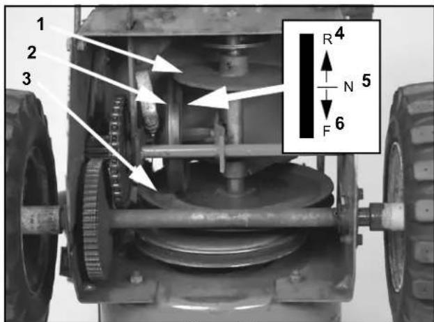
Figure 71
2768-024
-
Reverse plate
-
Friction wheel
-
Forward plate
-
Rubber wheel
up = reverse
- Rubber wheel in
middle = neutral
- Rubber wheel
down = forward
The most convenient method of working on the traction drive is to stand the machine up on the auger.
- Drain both fuel and oil from the engine.
- Stand the machine up on its auger and secure to prevent tipping (Figure 72).
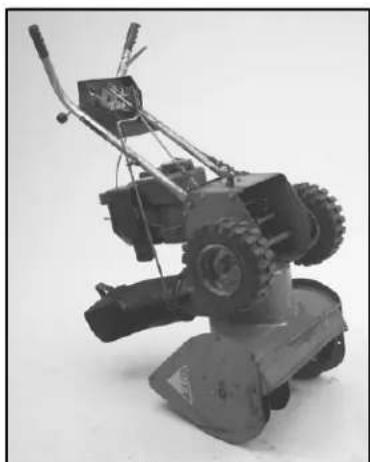
natural_image
Black-and-white photo of a small manual lawn mower with visible blades and levers (no text or symbols)Figure 72
2768-027
- Remove 4 self-tapping screws securing the lower shield.
- Remove the klik pins and both wheels.
- Each end of the axle is supported by a bearing which is attached to the chassis by two thread forming screws. At minimum, the screws must be removed from the bearing on the left side in order to remove the axle. The right side axle bearing can also be removed (Figure 73).
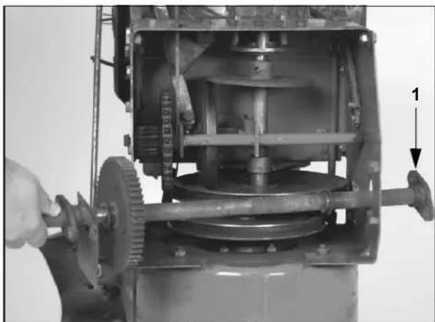
natural_image
Mechanical assembly view showing a motor with gears and shaft, no visible text or symbolsFigure 73
2768-026
- Beanng
3 - 2 Two Stage Snowthrower Drive Systems Manual
- The axle can now be removed from the chassis. Inspect the gear, the roll pin, and the areas where the bearings contact the axle for damage or severe wear. Remove the thrust washers from either end of the axle. The purpose of the roll pin and thrust washers is to limit the side to side movement of the axle.
- Disconnect the two clevis pins on the shift linkage rods.
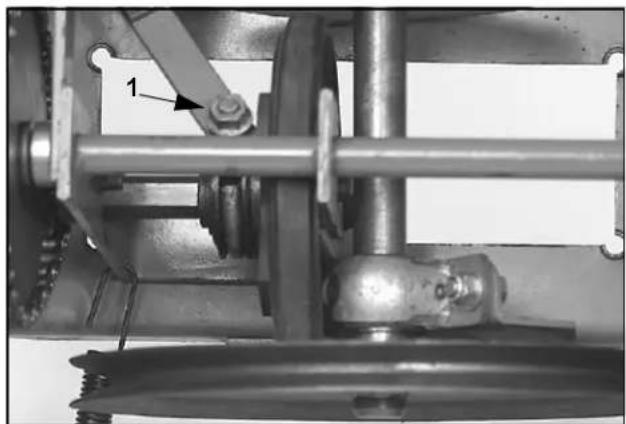
- Next to the friction wheel is a large eyebolt, which is connected to the shift linkage (Figure 74). Remove the flange nut and washer from the end of the eyebolt. Note the location and type of washers. You should be able to slip the linkage off of the eyebolt. If not, loosen the shoulder screw that the linkage pivots on.
natural_image
Mechanical assembly diagram showing a chain with labeled component 1 (no text or symbols beyond label)Figure 74
2768-32A
-
Flange nut/eyebolt
-
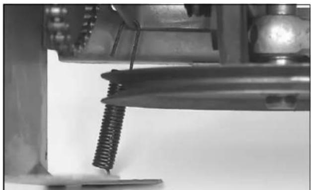
There is a spring connected between the left front corner of the pivot shaft (that contains the friction wheel) forward to a tab on the chassis. Unhook one end of this spring (Figure 75).
natural_image
Close-up of a mechanical component with a spring attached, showing no visible text or symbols.Figure 75
2768-32B
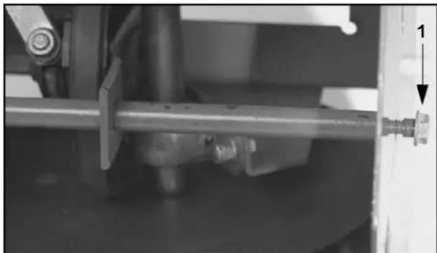
- The pivot shaft, which contains the friction wheel, is retained by two shoulder bolts. They pass through the side plate, into the ends of the shaft. Remove these two bolts and the pivot assembly will slide out of the chassis (Figure 76).
natural_image
Mechanical assembly showing a shaft and housing with a numbered component (no visible text or symbols)Figure 76
2768-033
-
Shoulder bolt
-
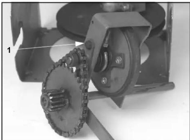
To disassemble the pivot assembly, proceed as follows (Figure 77):
natural_image
Mechanical assembly showing a chain and gear mechanism (no visible text or symbols)Figure 77
2768-036
- Hex shaft bearing
A. The drive chain contains a master link. Separate that and remove the chain.
B. To remove the friction wheel, remove four cap screws securing the hex shaft bearings. Slide the bearings off the ends of the hex shaft.
C. The hex shaft can now be removed from the pivot assembly.
D. If the friction wheel is to be replaced, remove the four screws and lock nuts connecting it to the traction drive hub.
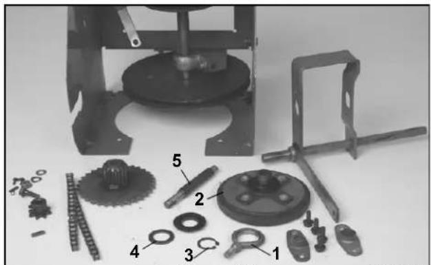
E. If the eyebolt, or traction drive hub is to be replaced, remove the snap ring on the hub (Figure 78).
natural_image
Exploded view of mechanical assembly with numbered parts (1-5), no visible text or symbolsFigure 78
2768-040
-
Eye bolt
-
Snap ring
-
Rubber wheel and hub
-
Spacers
-
Hex shaft
F. The small sprocket is retained to the hex shaft with a key and set screw.
G. The large sprocket just rotates on the bearings, so it will slide off the shaft.
- The drive shaft assembly is held in place by a front pillow block bearing and a bearing on the rear with spacers to locate everything front to rear. Remove two cap screws holding each bearing in place. Remove the shaft assembly (Figure 79).
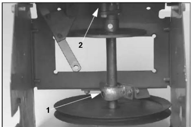
Figure 79
2768-043
-
Front bearing
-
Rear bearing
-
Note the location of the thrust washers and spacers. Drive the roll pin out of the end of the drive shaft and remove the bolt securing the reverse drive plate. All the parts will slide off the drive shaft.
3 - 4 Two Stage Snowthrower Drive Systems Manual
ASSEMBLY — TORO MODELS 38065, 38080, 38085
Preparation
- Before assembling something with a new bushing, wipe the bushing with a clean shop towel. This should remove any debris that might have gotten into the bushing during shipping and storage.
- These are oil-impregnated bearings. However, before installing them on a shaft, wipe the bearing surface with a clean shop towel. Then apply a light coat of engine oil to the bearing surface.
- Apply oil sparingly in this drive system. Excess oil will be thrown around during operation and can cause the friction wheel to slip.
- Wipe the drive plate and friction wheel with alcohol to make sure they are clean, to prevent slippage.
Assembly
- Slide the pillow block bearing, reverse plate (with the hub side away from the pulley), thrust washer, bearing (hub side facing the reverse plate), thrust washer, and spacer onto the drive shaft. Drive the roll pin through the spacer and shaft. Secure the reverse plate with the cap screw and locknut (Figure 80).
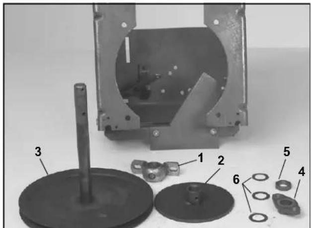
Figure 80
2768-046
- Pillow block bearing
- Reverse plate
- Pulley/forward plate
- Rear bearing
- Spacer
-
Thrust washer
-
Install the pillow block bearing loosely. Secure the rear bearing to the center frame.
-
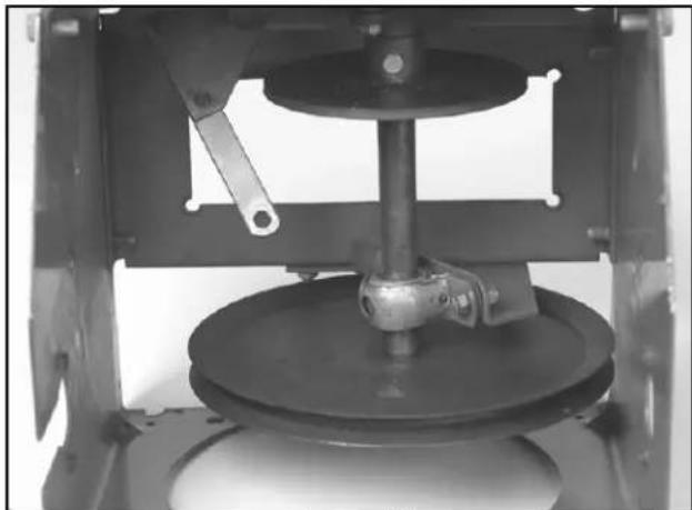
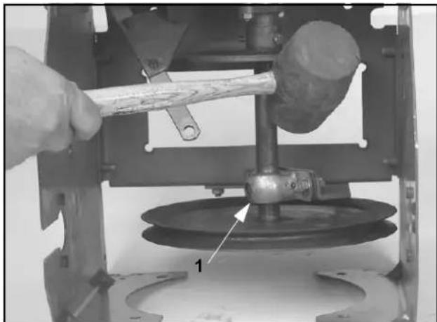
The shaft should be parallel to the sides of the chassis (Figure 81). The pillow block bearing has slotted mounting holes to provide adjustment. Tighten the cap screws on the pillow block bearing. While rotating the pulley, strike the pillow block bearing with a rubber mallet (Figure 82). This helps the bearing align itself with the shaft. If the shaft turns with difficulty, loosen the cap screws on the pillow block bearing and rotate the pulley. Then secure the cap screws.
natural_image
Close-up of a mechanical device with a central rotating wheel and surrounding components (no visible text or symbols)Figure 81
2768-041
natural_image
Close-up of a hand using a hammer to press or install a mechanical component, with no visible text or symbols.Figure 82
2768-047
-
Pillow block bearing
-
If the pivot assembly was repaired, now is the time to assemble it.
A. Secure the friction wheel to the hub with four cap screws and locknuts. If the locknuts are worn, apply a drop of Loctite™ Red #271 or equivalent to the threads.
B. Slip a slider ring on either side of the eyebolt and slide it on the hub. Install the spacer and snap ring. Note the snap ring must be installed with the sharp edge facing outward (away from the friction plate) (Figure 83).
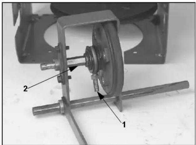
Figure 83
2773-049
-
Eye bolt
-
Hex shaft
C. If the hex shaft is rusty, now is the time to clean it with a wire brush or emery cloth. Apply a very light coat of engine oil to the shaft. A thin coat will prevent rust, but too much will be flung around the drive system during operation. A very thin coat of Lubriplate™ MAG-1 could be use here as an alternative to oil. Ordinary grease will thicken in cold weather and cause a hard shifting problem.
D. To assemble the pivot shaft assembly, hold the shaft with the flat bar that the linkage attaches to pointing towards you.
E. The hub and friction wheel goes inside the frame with the hub to your left. Insert the hex shaft into the hub with the keyway on the left. Slide the bearings on the hex shaft (Figure 83). Note the hub on both bearings should face to the left. Secure both bearings with self-tapping screws. The friction wheel should spin without binding.
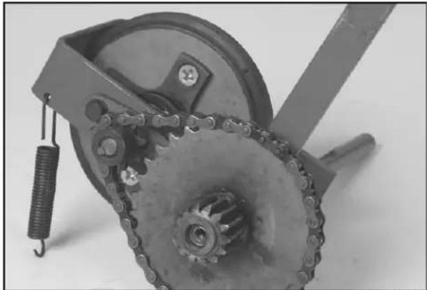
F. Hook the long end of the spring in the hole in the left front corner of the frame (Figure 84).
natural_image
Mechanical gear assembly with chain and worm-like components (no visible text or symbols)Figure 84
2773-051
G. Slide the spacer on the right hand side. Clean the bushings and install them in the sprocket with a light coat of oil. Lightly oil the inside of the bushing and slide the sprocket on with the gear to the outside.
H. Now insert the key into the keyway and slide the small sprocket on. Align the sprockets and tighten the setscrew in the small sprocket. Install the chain. Lubricate the chain with chain oil. If you use engine oil, use a very light coat, as it will be thrown around the drive system (Figure 84).
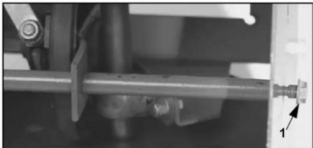
- The pivot assembly is installed by first feeding the flat arm through the slot in the center frame. Align the pivot assembly with the holes in the side plates. Note that there are special shoulder bolts. The shoulder must pass through the side plate and bottom on the end of the shaft (Figure 85). After securing the bolts, check to be sure the pivot assembly can rotate. If not, check the pivot bolts to see if the side plate was pinched between the bolt and pivot shaft.
natural_image
Mechanical assembly diagram showing a shaft and housing with a numbered component (no text or symbols visible)Figure 85
2768-033
-
Shoulder bolt
-
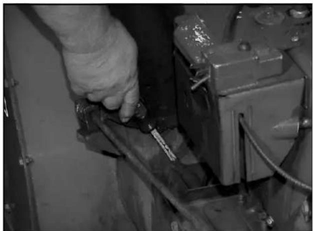
Next, tension the pivot assembly. With the unit upright, use a screwdriver to stretch the traction spring and hook it into the hole provided (Figure 86).
natural_image
Close-up of a hand using a tool to adjust or install a mechanical component (no visible text or symbols)Figure 86
MVC-714
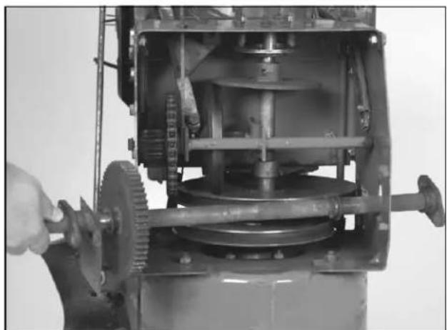
- Slip one thrust washer on each end of the axle and insert it into the chassis. Lightly oil the inside of the bearings and slip one on each end, with the hub pointing inward. Secure each bearing with two thread forming screws (Figure 87).
natural_image
Close-up of a mechanical pump assembly with gears and shafts, no visible text or symbolsFigure 87
2768-026
- Coat the end of the axles with anti-seize or a water repellent grease and install the wheels with the click pins.
- Lower the machine to the ground, check the linkage adjustments, fill with fuel and oil, and test run.
DISASSEMBLY — LAWN-BOY MODELS 28230, 23231 AND TORO MODELS 38051, 38052, 38054, 38056, 38062, 38063, 38064, 38072, 38073
- Drain the gasoline and oil.
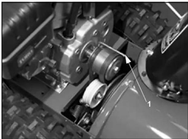
- Remove the belt cover. Loosen the belt guide, do not bend. Remove the auger and traction belts (Figure 88).
natural_image
Close-up of a mechanical assembly showing gears and a shaft, with no visible text or symbolsFigure 88
2773-014
1. Belt guide
- Stand the unit up on its auger and secure to prevent tipping.
- Remove the bottom cover.
- Remove the klik pins and slide both wheels off the axle.
Traction Drive Systems
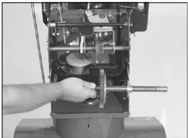
- Remove 4 self-tapping screws that secure the axle bearings to the traction frame. Lift the axle and bearings out (Figure 89). Slide the bearings and thrust washers off the axle.
natural_image
Close-up of a hand operating a mechanical device with gears and shafts (no visible text or symbols)Figure 89 2773-074
- Disconnect the shift rod and traction drive rod.
- If the friction plate frame spring (traction belt tension) did not unhook when the belt was removed, unhook it now (Figure 90).
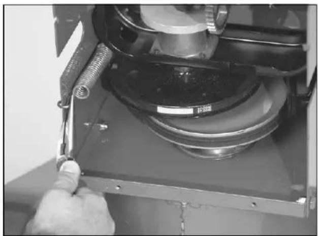
natural_image
Close-up of a hand using a tool to adjust or install a mechanical component, no visible text or symbols.Figure 90 2773-077
- To remove the traction engagement assembly, remove the retaining ring on the left side of the frame. Note: Some older models use a cap screw through the side plate into the end of the shaft. Slide the shaft to the side and it will disengage from the chassis (Figure 91).
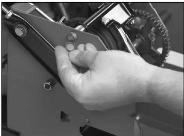
natural_image
Close-up of a hand adjusting a mechanical component with bolts and gears (no visible text or symbols)Figure 91 2773-079
- To remove the friction wheel and bracket assembly, remove the bolt that goes through the side plate into each end of the shaft. The gear quadrant fingers should disengage themselves from the sliding bracket that contains the friction wheel (Figure 92).
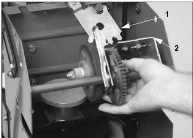
Figure 92 2773-081
1. Gear quadrant 2. Sliding bracket
- If it is necessary to remove the gear quadrant, it is best to just remove the two self-tapping screws that secure the gear quadrant mount to the traction frame. The gear quadrant and gear quadrant frame can then be separated easily (Figure 93).
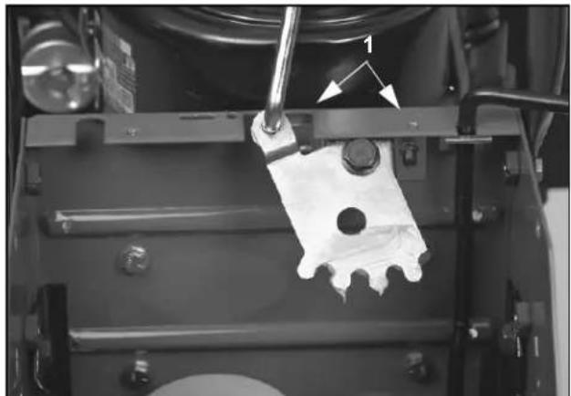
natural_image
Close-up of a mechanical assembly with a metal bracket and tool, no visible text or symbolsFigure 93
2773-082
-
Self-tapping screws
-
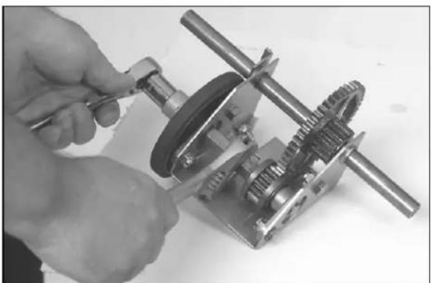
To disassemble the gear quadrant, hold the hex shaft with an open-end wrench. Remove the locknut on the end of the hex shaft (Figure 94).
natural_image
Close-up of a hand using a tool to adjust or install a mechanical gear assembly (no visible text or symbols)Figure 94
2773-085
- The friction wheel and hub will slide off the shaft. Remove 4 screws to separate the hub and wheel.
- Now the two bearings that support the hex shaft can be removed.
-
To remove the pivot shaft, drive out the roll pins on either side of the double gear. The shaft will then slide out of the gear and bracket.
-
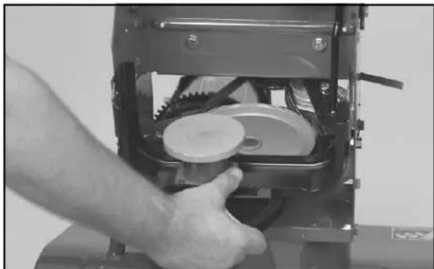
To remove the front frame, pulley, and drive plate assembly, remove the two shoulder bolts that the frame pivots on. The assembly will then lift out of the chassis (Figure 95).
natural_image
Close-up of a hand operating a mechanical device with gears and a lid (no visible text or symbols)Figure 95
2773-001
- To service the drive plate, pulley, and hub, hold the pulley and unscrew the drive plate. It is left hand thread so rotate the plate clockwise to remove (Figure 96).
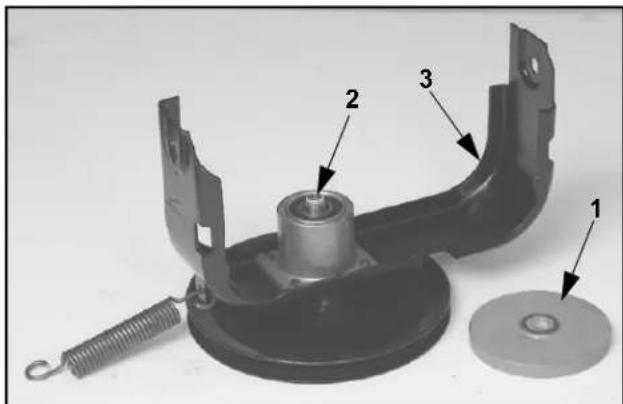
Figure 96
2773-005
- Drive plate
2 Hub
— LH thread
-
Front frame
-
The hub contains one ball bearing and one bushing.
- The hub can be separated from the front frame by removing 4 screws.
ASSEMBLY — LAWN-BOY MODELS 28230, 23231 AND TORO MODELS 38051, 38052, 38054, 38056, 38062, 38063, 38064, 38072, 38073
Assembly Tips
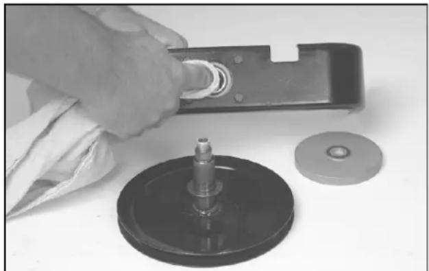
- Before assembling something with a new bushing, wipe the bushing with a clean shop towel. This should remove any debris that might have gotten into the bushing during shipping and storage (Figure 97).
natural_image
Close-up of a hand using a tool to adjust a mechanical component, with a circular base and washer nearby (no visible text or symbols)Figure 97
2773-008
- Add a drop or two of 30 weight engine oil before assembly. This will ensure good lubrication upon start up.
- It is important to minimize oil in this area. Too much oil will be thrown about when running. Oil on the drive plate or friction wheel will result in drive slippage.
- Wipe the drive plate and friction wheel with alcohol to make sure they are clean, to prevent slippage.
- Do not use general-purpose grease to lubricate drive components. In cold temperatures, it will stiffen and can prevent shifting.
Assembly Steps
- Assemble the hub to the front frame using 4 screws.
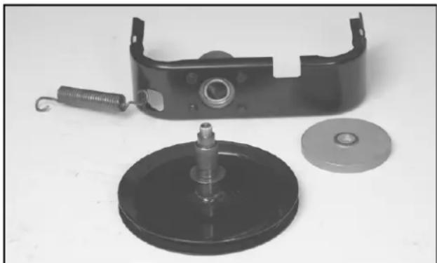
- Install the snap ring onto the pulley and shaft. Assure the sharp edge of the snap ring faces towards the pulley (Figure 98).
natural_image
Black mechanical component with a spring, disc, and washer (no text or symbols visible)Figure 98
2773-006
- Install the pulley in the hub and install the drive plate (left hand thread). Tighten firmly.
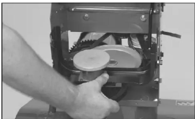
- Install the front frame into the chassis using two shoulder bolts. Tighten firmly (Figure 99).
natural_image
Close-up of a hand operating a mechanical device with gears and a disc (no visible text or symbols)Figure 99
2773-001
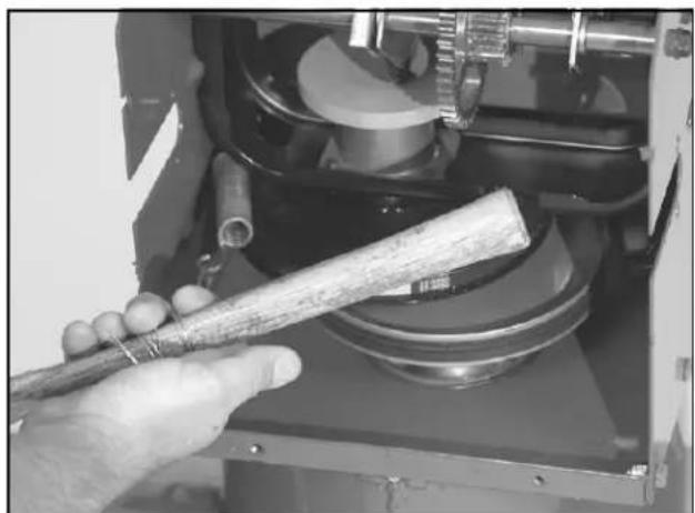
- Install the friction plate spring into the front frame assembly. Note some models just have a hole in the frame. Others have a tab bent outward to hook the spring into (Figure 100). Hook the lower end of the spring into the notch in the traction frame.
natural_image
Close-up of a hand holding a wooden tool inside a mechanical device (no visible text or symbols)Figure 100
2773-078
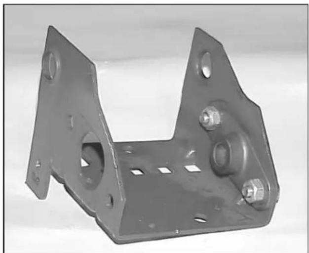
- Begin assembly of the friction wheel and sliding bracket by installing the right side (opposite the friction wheel) bearing (Figure 101).
natural_image
Metal bracket component with bolt holes and mounting holes (no text or symbols visible)Figure 101
MVC-862
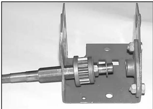
- Lightly oil the hex shaft. Insert the hex shaft from the left side, non-threaded end first. Slip the shaft through the left side of the sliding bracket (Figure 102).
natural_image
Mechanical assembly component with metallic shaft and housing (no visible text or symbols)Figure 102
MVC-864
- Place the pinion gear on the hex shaft (larger OD to the left). Add the thrust washer, then insert the shaft into the previously mounted bearing.
- Install a thrust washer and the second bearing. Tighten the bearing mounting bolts securely.
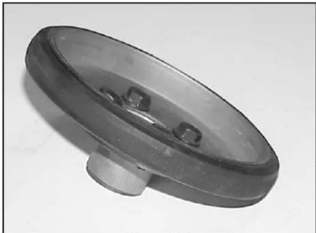
- Assemble the friction wheel and hub using 4 self-tapping screws. Note the hub mounts to the flat side of the friction wheel (Figure 103).
natural_image
Close-up of a small, reflective mechanical component with a circular top and central base (no text or symbols visible)Figure 103
MVC-718
Traction Drive Systems
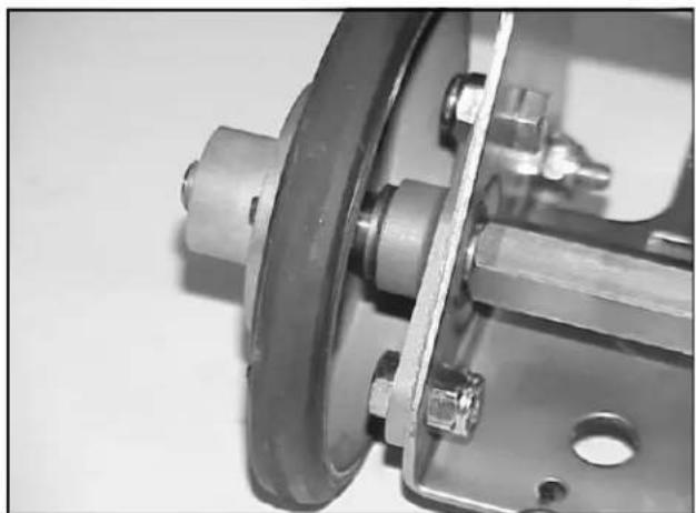
- Slide the wheel and hub on the hex shaft with the friction wheel closest to the sliding bracket. Install the locknut, holding the hex shaft with an open-end wrench (Figure 104).
natural_image
Close-up of a mechanical assembly with a flanged component and bolted joints (no visible text or symbols)Figure 104
MVC-720
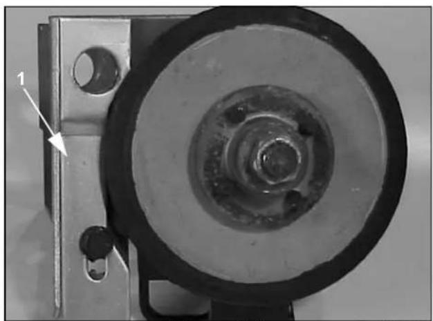
- If the receiver cam has been removed, install it now.
natural_image
Close-up of a mechanical pulley or wheel assembly with a circular head and bolt, showing no visible text or symbols.Figure 105
MVC-865
1. Receiver cam
- Insert the pivot shaft through the cam receiver then the washer, double gear, another washer, then through the other end of the sliding bracket (Figure 105).
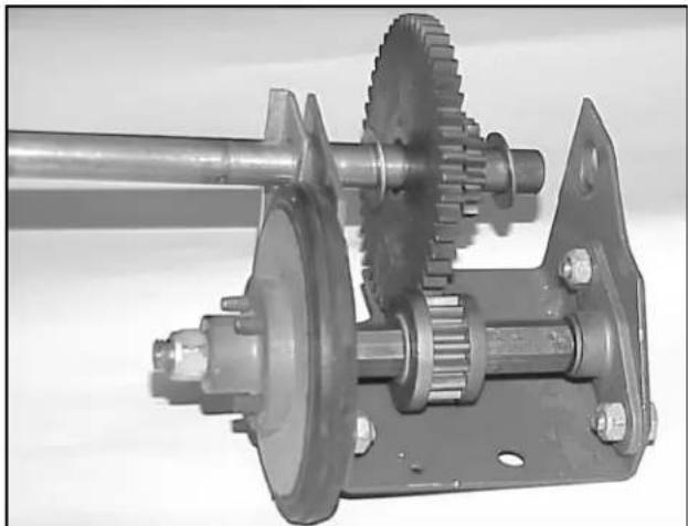
- Line up the gears using the holes in the pivot shaft. The longer end of the shaft must be on the side with the friction wheel. Secure with two roll pins (Figure 106).
natural_image
Mechanical gear assembly with shaft and housing components (no visible text or symbols)Figure 106
MVC-866
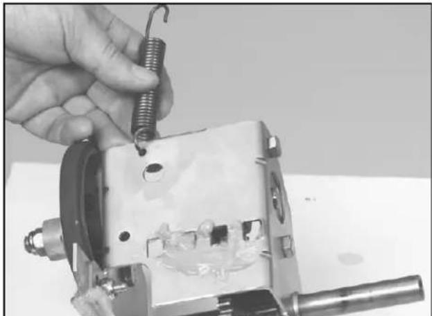
- Connect spring to hole in front of pivot assembly (Figure 107).
natural_image
Close-up of a hand holding a spring attached to a mechanical component (no visible text or symbols)Figure 107
2773-084
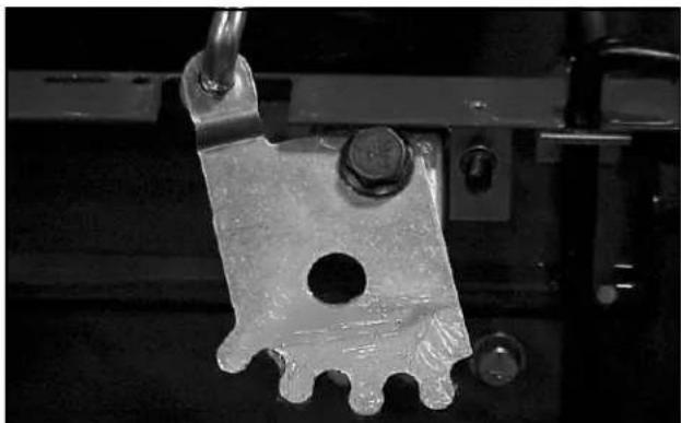
- Assemble the gear quadrant and the mounting bracket. (Figure 108).
natural_image
Close-up of a metallic mechanical component with a hole and mounting bracket (no visible text or symbols)Figure 108
MVC-719
- Install the friction wheel and sliding bracket. The friction wheel should be on your left (Figure 109).
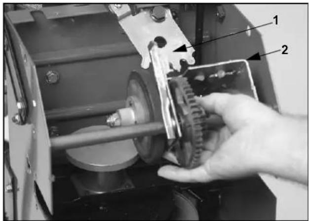
Figure 109
2773-081
-
Gear quadrant
-
Sliding bracket
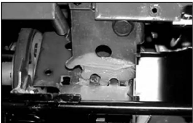
The gear quadrant must be free to pivot. The first tooth on the quadrant should go into the hole in the right side as shown in Figure 110.
natural_image
Close-up of mechanical components with no visible text or symbolsFigure 110
MVC-716
Secure with 2 shoulder bolts. One through each side of the frame into the shaft. Assure the shaft is free to pivot. If not, loosen the shoulder bolts and relieve the binding (Figure 109).
-
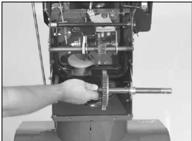
Clean the axle so dirt or rust does not damage the bearing during installation.
-
Install a thrust washer and bearing on each end of the axle. Locate the holes and secure the axle bearings to the frame (Figure 111).
natural_image
Close-up of a hand operating a mechanical device with gears and shafts (no visible text or symbols)Figure 111
773-074
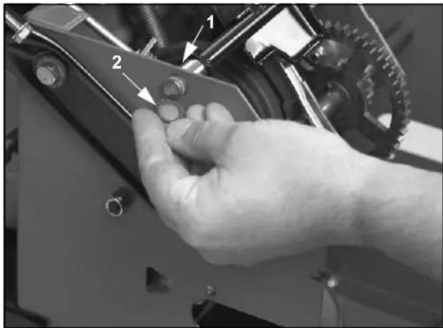
- Slip the spacer on the end of the traction engagement assembly. Slide the assembly into the holes in the frame and secure the left end of the shaft with a retaining ring (Figure 112).
natural_image
Close-up of a hand adjusting a mechanical component with labeled parts (1 and 2), no visible text or symbols beyond labels.Figure 112
2773-079
-
Spacer
-
Retaining ring
Traction Drive Systems
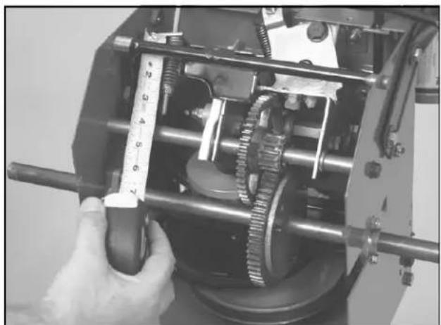
- If the lower traction rod was removed, reinstall it now. Slide the end through the traction bracket then install the spring and locknut. Turn the locknut on until the spring is compressed to approximately 214 " (5.7 cm) long (Figure 113).
natural_image
Close-up of a mechanical gear assembly with a hand holding a tool, no visible text or symbolsFigure 113
2773-010
- Install the bottom cover and reconnect any additional linkage that may have been removed.
- See "Auger/Impeller Drive Control Linkage — All Other Models" on page 2 - 8 and "ADJUSTING THE TRACTION ROD — LAWN-BOY MODELS 28230, 28231 AND TORO MODELS 38051, 38052, 38054, 38056, 38062, 38063, 38064" on page 2 - 11 to make all final linkage adjustments.
DISASSEMBLY — TORO MODELS 38066, 38078, 38083, 38084, 38086
- Drain the fuel and oil. Stand the machine up on its auger and secure to prevent tipping.
- Remove the klik pins and remove both wheels.
- Remove 8 self-tapping screws securing the lower cover and rear plate (Figure 114).
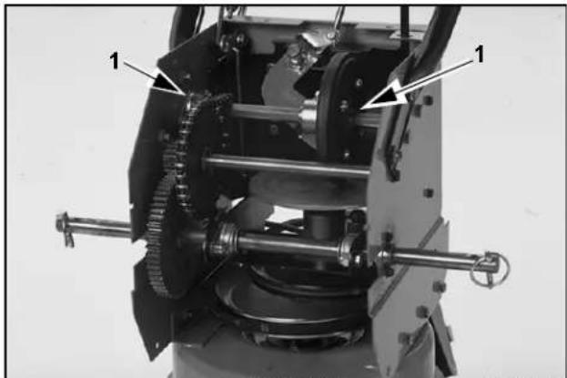
natural_image
Mechanical assembly diagram showing gears and shafts with labeled components (no readable text or symbols)Figure 114
0054-007
-
Iraction shaft bearings
-
To remove the upper traction shaft and friction wheel assembly, disconnect the master link in the chain. Remove the two bolts securing the bearings on each side and slide the assembly out of the frame (Figure 115).
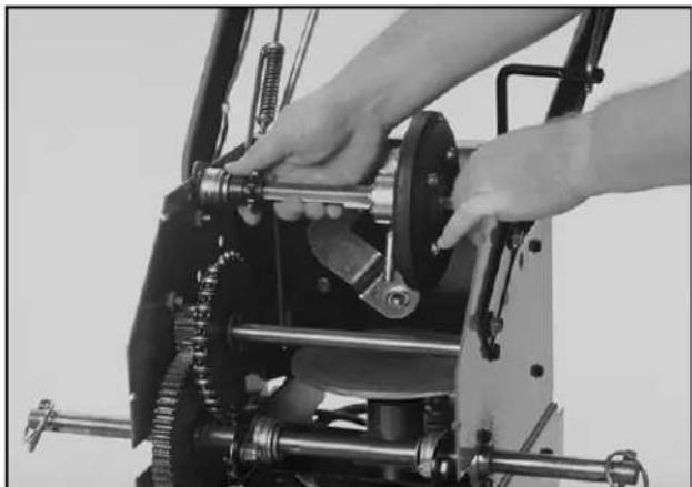
natural_image
Close-up of hands operating a mechanical device with gears and levers (no visible text or symbols)Figure 115
0054-008
-
For service of the traction shaft assembly, refer to "SUB ASSEMBLY REPAIR — TORO MODELS 38066, 38078, 38083, 38084, 38086" on page 3 - 17.
-
To remove the intermediate shaft, loosen the retaining bolts and remove the chain. Loctite™ Red #271 is used to secure these bolts. Remove the shaft (Figure 116).
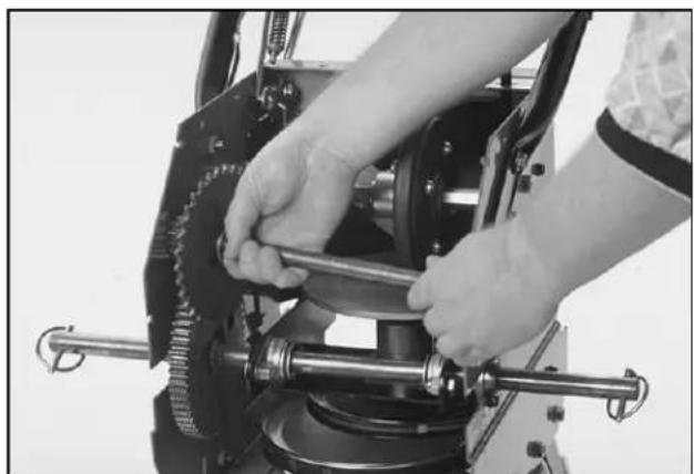
natural_image
Close-up of hands operating a mechanical gear assembly with rotating components (no visible text or symbols)Figure 116
0054-009
- To remove the axle and friction plate assembly, disconnect the traction idler spring (shown just below the right side axle bearing) (Figure 117).
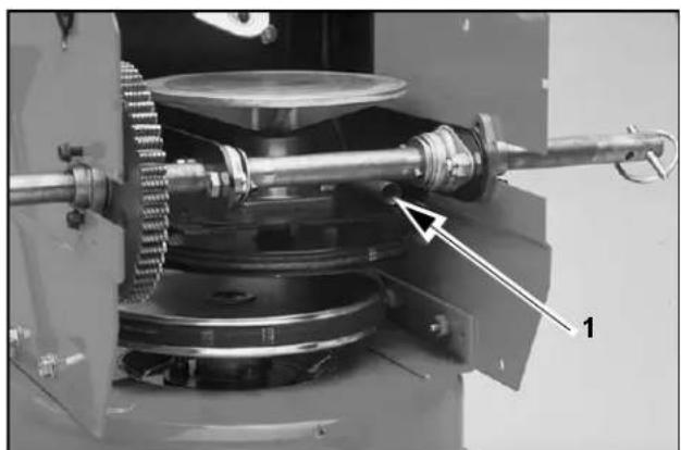
natural_image
Mechanical assembly diagram showing gears and shafts with labeled component '1' (no text or symbols beyond labels)Figure 117
0054-010
-
Spring
-
Disconnect the friction plate disengagement spring (in the upper left corner of the traction housing) (Figure 118).
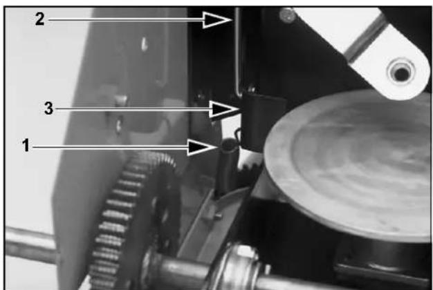
Figure 118
0054-011
-
Spring
-
Bell crank
-
Traction
engagement rod
-
At this point the traction belt must be removed. Refer to "Replacing the Traction Belt — Lawn-Boy Model 28232 and Toro Models 38053, 38066, 38078, 38083, 38084, 38086" on page 2 - 4.
-
Disconnect the traction engagement rod (left front corner) from the bell crank (Figure 118).
-
Remove the retaining bolts from the axle bearings and the friction plate and axle will slide out of the chassis.
-
For servicing, refer to "Axle and Friction Plate Assembly" on page 3 - 19.
ASSEMBLY — TORO MODELS 38066, 38078, 38083, 38084, 38086
Reverse the process for assembly. See the following tips for special information.
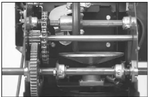
- Lightly grease the axle gear. Spread about 12 teaspoon of #2 general-purpose grease around the circumference of the gear (Figure 119). Excess grease will just fling off when the machine is driven.
natural_image
Mechanical gear assembly with interlocking gears and shafts (no visible text or symbols)Figure 119 2768-017
-
Lightly oil the drive chain with chain oil. If engine oil is used, coat the chain then wipe the excess off. As with the grease, the sprockets turning will fling any excess oil around the drive system.
-
The drive plate must be clean and free of oil. Wipe with alcohol or a solvent that does not leave a residue. Oil on the plate will cause drive slippage.
-
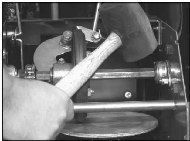
When installing the traction shaft and friction wheel, the bearings must be aligned. Loosely install the assembly into the chassis. Rotate the friction wheel and firmly strike each bearing a couple of times with a rubber mallet (Figure 120). The jolt will center the bearings. Secure the bearings to the chassis side plates.
natural_image
Close-up of hands operating a mechanical tool with a metal rod and circular base (no visible text or symbols)Figure 120 2768-019
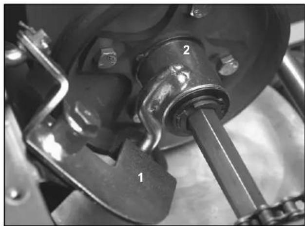
- The rod that is welded to the slider must slip into the end of the shift arm assembly (Figure 121).
natural_image
Close-up of a mechanical assembly with labeled parts (1, 2), no readable text or symbols beyond labelsFigure 121 2768-020
- Shift arm 2. Slider assembly
SUB ASSEMBLY REPAIR — TORO MODELS 38066, 38078, 38083, 38084, 38086
This section will cover the disassembly and repair of the traction shaft/friction wheel and the axle and friction plate assembly after they have been removed from the chassis.
Traction Shaft/Friction Wheel Disassembly
- With the assembly out and on the bench, the bearings will just slide off the shaft (Figure 122).
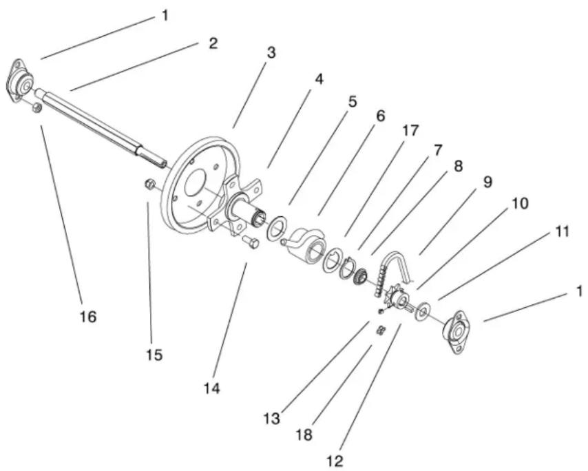
Figure 122
38086-02
- Bearing-triangle
- Shaft-hex
- Friction wheel
- Hub-traction disc
- Washer-thrust
-
ASM-Slider ring
-
Ring-retaining
- Spacer
- Roller chain
- Sprocket
- Washer-thrust
-
Key-square
-
Screw-HS
- Screw-HH
- Nut-lock Ni
- Nut-lock Ni
- Washer-thrust
-
Link-chain
-
Note the locations of all thrust washers before removing them.
-
The small sprocket is keyed and set screwed to the shaft. Remove the sprocket then the spacer.
-
The friction wheel, hub, and slider ring will slide off the hex shaft.
- The friction wheel can now be replaced by removing the 4 cap screws and locknuts that secure it to the hub.
Traction Drive Systems
- There are 2 versions of the hub and slider. The early models use a normal thrust washer on either side of the slider. Later models use a thrust washer with an internal key that fits into a keyway cut into the shaft portion of the hub. This keyed version is current; if the older hub is ordered, you will automatically get the new version (Figure 123).
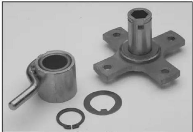
natural_image
Mechanical parts including a cylindrical housing, hexagonal bolt, and multiple ring components (no text or symbols visible)Figure 123 0723-001
Assembly
-
Inspect the hex shaft for nicks, burrs, or rust. Clean and deburr as necessary.
-
Coat the hex shaft with a light coat of engine oil, just enough to prevent rust. Do not use grease as it will stiffen in the cold and prevent shifting.
-
If you are reusing the old hub, assure it is clean and free of burrs.
-
The slider contains an oil impregnated bearing. Wipe the inside of the bearing with a clean shop towel to assure there are no burrs or debris. Apply 2 or 3 drops of clean engine oil to the inside of the bearing, install it on the shaft as shown (Figure 122). Secure with the keyed thrust washer and snap ring. Note the sharp edge of the snap ring should face away from the slider.
-
Slide the spacer, sprocket, and key into place. The shoulder on the sprocket should face away from the slider. Apply a drop of Loctite™ Blue #242 to the set screw and secure the sprocket to the shaft.
Axle and Friction Plate Disassembly
- The pulley and shaft go through the bearing hub and the drive plate screws on. Note: The threads are left hand. Rotate clockwise to remove the plate. You may find it easier to clamp the drive plate in a vise and unscrew the pulley (Figure 124).
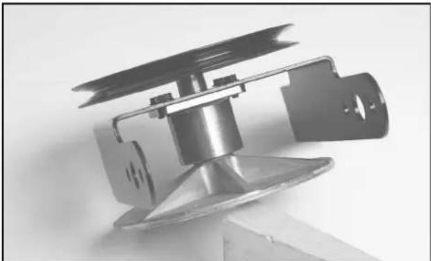
natural_image
Cross-sectional view of a mechanical device with internal components (no visible text or symbols)Figure 124 1577-019
- The pulley and shaft can now be drawn out of the hub. Note the thrust bearing and snap ring locations (Figure 125).
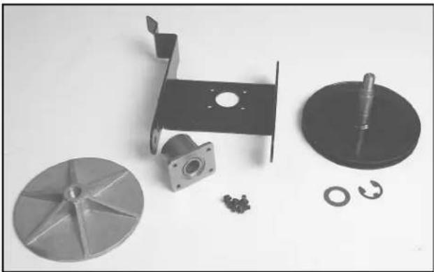
natural_image
Collection of mechanical parts including a metal frame, motor, and washer (no text or symbols visible)Figure 125 1577-023
-
Drive the 3 roll pins out of the axle. The axle will now slide out of the bearings.
-
The bearings can now be removed from the frame.
-
Remove 4 self-tapping screws that secure the hub to the friction plate frame.
Axle and Friction Plate Assembly
Assemble in reverse order. The following are notes to assist you:
- Install the snap ring into the grove in the pulley and shaft. The sharp edge of the snap ring should face the pulley. Install the thrust bearing next to the snap ring (Figure 126).
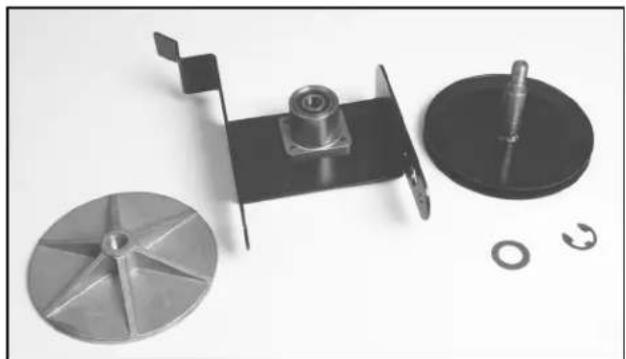
natural_image
Exploded view of a mechanical assembly with components like a fan, washer, and washer (no text or symbols visible)Figure 126
1577-020
- Fill the cavity between the bearings of the hub assembly with No. 2 general-purpose grease before installing the pulley and shaft (Figure 127).
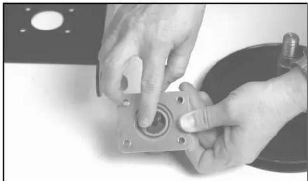
natural_image
Close-up of hands assembling a mechanical component with a circular housing (no visible text or symbols)Figure 127
1577-024
-
Remember the threads on the pulley and shaft and the drive plate are left hand. Tighten firmly.
-
Install the bearings on the friction plate frame. Do not tighten yet.
-
After the axle is installed, rotate the axle and firmly strike each bearing with a rubber mallet. This helps align the bearings with the axle. Secure the bearings to the frame.
THIS PAGE INTENTIONALLY LEFT BLANK
- LAWN-BOY®
- 2-Stage Snowthrower Drive Systems Service Manual
- AUGER GEARBOX SERVICE ..... 1-1
- BELTS, CONTROLS AND LINKAGES ..... 2-1
- THIS PAGE INTENTIONALLY LEFT BLANK
- GENERAL INFORMATION
- GEARBOX REMOVAL
- Primary Method — Minimum Disassembly
- Secondary Method — Traction and Auger Housings Separated: Toro Models 38065 and 38080
- Secondary Method — Traction and Auger Housings Separated: All Other Models
- INSTALLATION
- AUGER GEARBOX DISASSEMBLY / SERVICE
- Auger Gearbox Service
- Failure Analysis
- GEARBOX ASSEMBLY
- INTRODUCTION
- REPLACING THE AUGER/IMPELLER DRIVE BELT
- REPLACING THE TRACTION BELT
- Replacing the Traction Belt — Toro Models 38065, 38080, 38085
- CAUTION
- View from left side of unit
- CONTROL AND LINKAGE ADJUSTMENT
- Auger Control Adjustment — Toro Models 38065, 38080, 38085
- Install Auger Drive Control Rod
- Adjusting Auger/Impeller Drive Belt
- Auger/Impeller Drive Control Linkage — All Other Models
- - 8 Two Stage Snowthrower Drive Systems Manual
- ADJUSTING TRACTION CONTROL
- Adjusting the Traction Control — Toro Models 38065, 38080, 38085
- ADJUSTING THE TRACTION ROD — LAWN-BOY MODELS 28230, 28231 AND TORO MODELS 38051, 38052, 38054, 38056, 38062, 38063, 38064
- ADJUSTING THE SPEED SELECTOR
- TROUBLESHOOTING THE TRACTION DRIVE — ALL MODELS
- Drive slipping:
- DISASSEMBLY — TORO MODELS 38065, 38080, 38085
- - 2 Two Stage Snowthrower Drive Systems Manual
- - 4 Two Stage Snowthrower Drive Systems Manual
- ASSEMBLY — TORO MODELS 38065, 38080, 38085
- Preparation
- Assembly
- Traction Drive Systems
- Assembly Tips
- Assembly Steps
- DISASSEMBLY — TORO MODELS 38066, 38078, 38083, 38084, 38086
- ASSEMBLY — TORO MODELS 38066, 38078, 38083, 38084, 38086
- SUB ASSEMBLY REPAIR — TORO MODELS 38066, 38078, 38083, 38084, 38086
- Traction Shaft/Friction Wheel Disassembly
- Axle and Friction Plate Disassembly
- Axle and Friction Plate Assembly
Brand : TORO
Model : 38062
Category : Camera