
ABC1B - Refrigerator Artusi - Free user manual and instructions
Find the device manual for free ABC1B Artusi in PDF.


| Product Type | Integrated Gas Barbecue |
| Model | ABC1B |
| Brand | Artusi |
| Available Sizes | 60 cm (2 burners), 80 cm (3 burners), 100 cm (4 burners) |
| Nominal Heat Input (MJ/h) | 26 (60 cm), 39 (80 cm), 52 (100 cm) for Universal LPG; same for Natural Gas |
| Gas Type | Universal LPG or Natural Gas (convertible) |
| Injector Diameter (1/100 mm) | 100 (LPG) or 170 (Natural Gas) for 60/80/100 cm |
| Gas Pressure (kPa) | 2.75 (LPG) or 1.00 (Natural Gas) |
| Ignition | Automatic (battery) with manual lighting backup |
| Burners | 2, 3, or 4 depending on model |
| Cooking Surfaces | Cast iron grills and solid cooking plate (optional on 80/100 cm) |
| Cover Options | Low (thin) cover or high cover (cooking hood) |
| Oil Management | Removable drip pans at front |
| Installation | Built-in (island or against wall), outdoor use only |
| Clearance to Combustibles | 600 mm overhead, 300 mm sides, 200 mm rear |
| Ventilation Requirements | Minimum 20,000 mm² free area at high and low level for LPG cylinder compartment |
| Gas Connection | 9 kg portable LPG cylinder or fixed LPG/natural gas supply via licensed gas fitter |
| Materials | Stainless steel surfaces, cast iron grills |
| Cleaning | Warm soapy water; avoid abrasives; oil cast iron after cleaning |
| Maintenance | Check burners yearly; replace battery for ignition; inspect hose/regulator every 5 years |
| Safety Features | Thermocouple flame failure device on each burner |
| Warranty | 12 months for portable models; 24 months for built-in models (conditions apply) |
| Weight (approx.) | Approximately 30-40 kg depending on size |
Frequently Asked Questions - ABC1B Artusi
User questions about ABC1B Artusi
0 question about this device. Answer the ones you know or ask your own.
Ask a new question about this device
Download the instructions for your Refrigerator in PDF format for free! Find your manual ABC1B - Artusi and take your electronic device back in hand. On this page are published all the documents necessary for the use of your device. ABC1B by Artusi.
USER MANUAL ABC1B Artusi
Congratulations, you are now the proud owner of an ARTUSI cooking appliance. Thank you for purchasing ARTUSI and welcome to the ARTUSI Family.
This instruction manual has been specially created to inform you of the full range of features your ARTUSI appliance has to offer and serves as an introduction to getting the very best out of your ARTUSI appliance.
We present detailed information on each of the features your ARTUSI appliance consists of. Once you have read this section you will be able to choose the most appropriate settings for your appliance when cooking different types of food.
We ask you to read the instructions in this booklet very carefully as this will allow you to get the best results from using your appliance. KEEP THE DOCUMENTATION OF THIS PRODUCT FOR FUTURE REFERENCE.
TO REGISTER YOUR PRODUCT WITH ARTUSI, PLEASE FILL OUT THE WARRANTY CARD AT THE END OF
THIS BOOKLET AND POST IT TO: REPLY PAID 83617
LEICHHARDT NSW 2040
Dear Artusi Customer, please read this user manual carefully before using the product and, keep it permanently at your disposal.
Note: This user manual is prepared for more than one model. Some of the features specified in this Manual may not be available on your appliance.
All our appliances are only for domestic use, not for commercial use. Products marked with (*) are optional.
"THIS APPLIANCE SHALL BE INSTALLED IN ACCORDANCE WITH THE REGULA TIONS FORCE AND ONLY USED IN A WELL VENTILATED SPACE. READ THE INSTRUCTIONS BEFORE INSTALLING OR USING THIS APPLIANCE"
Refer to AS/NZS 5601 (Gas Installations)
"Conforms with the WEEE Regulations."
Congratulations
Congratulations and thanks for choosing our integrated barbecue. We are confident that it will be a pleasure for you to use our new barbecue. Before using the barbecue, we recommend reading the entire user guide, which provides a description of the barbecue and its functions. To avoid those risks that are always present when using a gas appliance, it is important to install it correctly and carefully read the safety instructions in order to avoid misuse and hazards.
We recommend you keep this instruction booklet for future reference and pass it to any subsequent owners. After removing the barbecue from its packaging, check to see that it is not damaged. If in doubt, do not use the appliance and contact your nearest customer service centre.

English

Contents
Product description......4
Components......6
Important safety instructions.... 8
Assembling the barbecue....11
Gas cylinder safety information....21
Installation instructions....22
Application of the thin cover or cooking hood..34
Usage instructions....36
Cleaning and care.... 41
Maintenance....44
Troubleshooting....45
Suggestion for the environment
Disposal information for users

- Most of the packaging material is recyclable. These materials should be disposed of through a local recycling centre or by putting them in appropriate collection containers.
- If you want to discard the product, contact your local authorities and ask about the correct method of disposal.
- Remove all transit and packaging material before use.
Product description

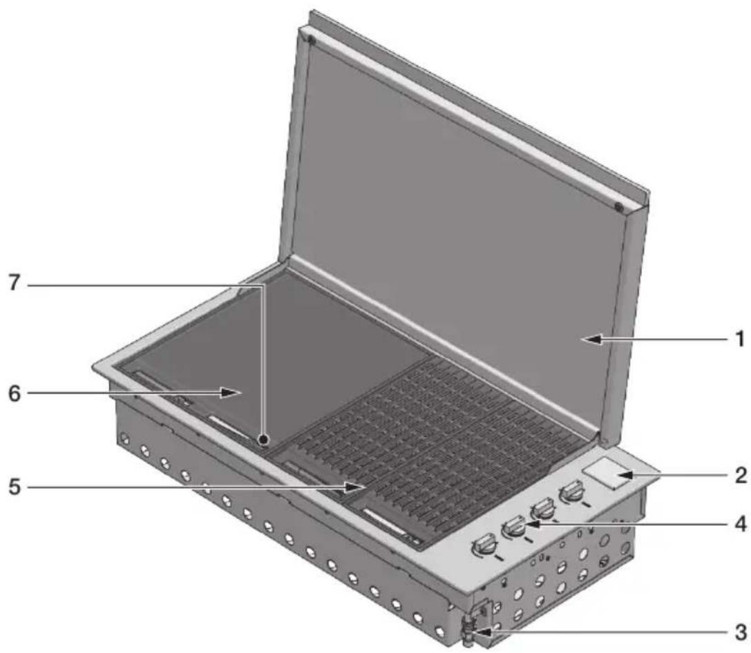
Integrated barbecue with thin cover
- Thin cover
- Battery compartment cover
- Gas connection point
- Burner controls
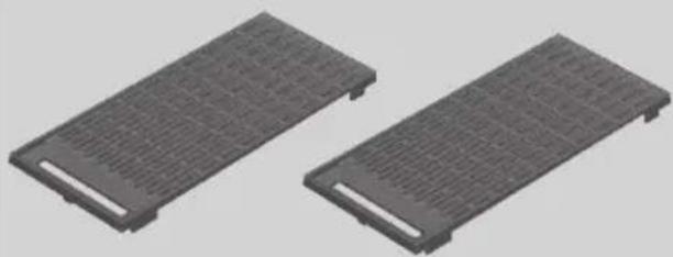
- Grill groups (2 sets)
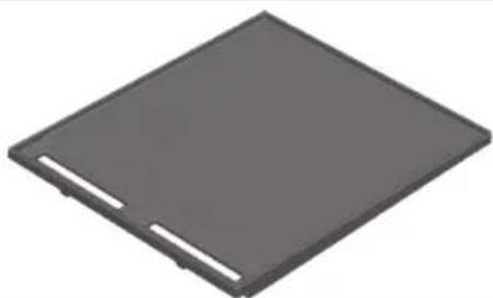
- Cooking plate
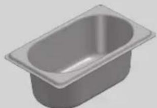
- Removable oil collection drip plan located in front of the barbecue (not shown)
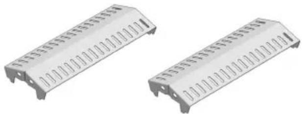
- Flame diffusers (2 pcs.) located under the grills (not shown)
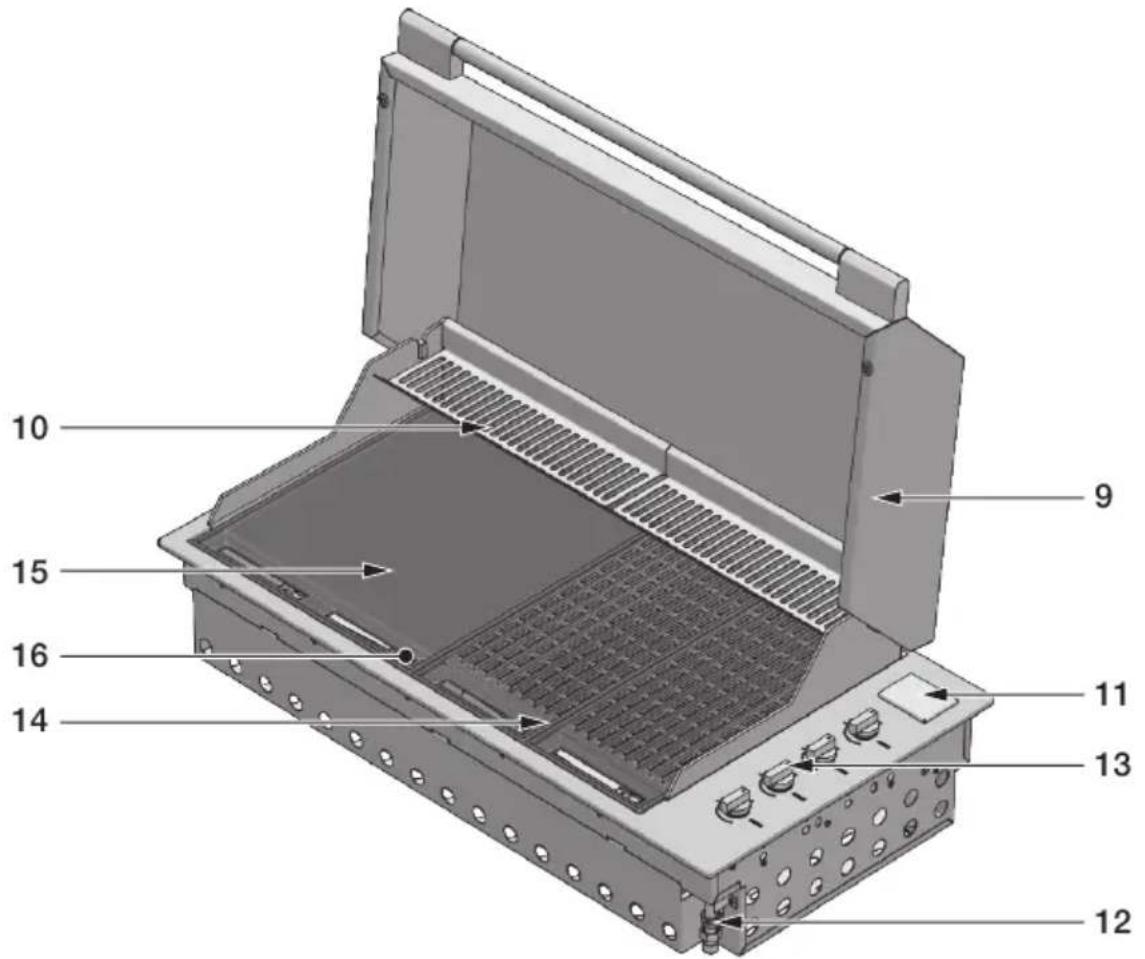
EN
Integrated barbecue high cover
- High cover
- Heating racks
- Battery compartment cover
- Gas connection point
- Burner controls
- Grill group
- Cooking plate
- Removable oil collection drip plan located in front of the cooking surface (not shown)
- Flame diffusers (2 pcs.) located under the grills (not shown)
Components

DESCRIPTION QTY
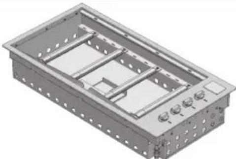
natural_image
3D rendering of a rectangular mechanical housing with internal compartments and mounting holes (no text or symbols)Burner box and external profile
1
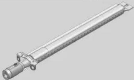
natural_image
3D rendering of a mechanical shaft component with flanges and mounting holes (no text or symbols)Burners
2 for 60cm model
3 for 80cm model
4 for 100cm model
natural_image
Two identical metallic electronic component blocks with slots and mounting holes (no text or symbols visible)Flame diffusers
2 for 60cm model
3 for 80cm model
4 for 100cm model
natural_image
3D rendering of a rectangular basin with a recessed top (no text or symbols)Oil tray 1
natural_image
3D rendering of a gray rectangular electronic component with cutouts (no text or symbols)Solid cooking plate only for 80 and 100cm models.
1
natural_image
Two gray rectangular electronic components with ventilation grilles, shown side by side (no text or symbols visible)Grill groups
2 for 60cm model
3 for 80cm model
4 for 100cm model
natural_image
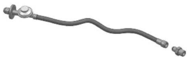
Mechanical component with a curved pipe and flanged ends, no visible text or symbolsUniversal LPG regulator and hose
1
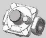
Natural gas regulator 1
CONFIGURATION 1
natural_image
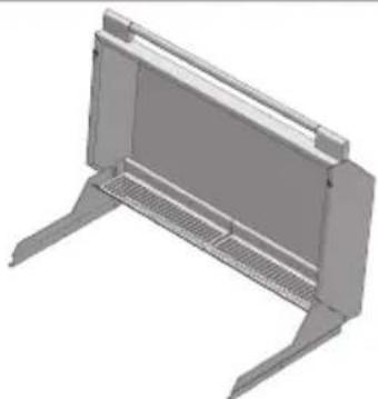
3D rendering of a modular electronic device with mounting legs and ventilation grilles (no text or symbols)High cover for cooking 1
CONFIGURATION 2
natural_image
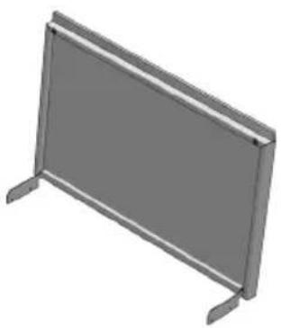
3D rendering of a flat-panel metal-framed panel with no text or symbolsLow cover 1
EN
Important safety instructions
For your own safety, you should read this manual before operating the barbecue.
Use

Carefully read the user manual and keep it in a handy place for future reference. Below, we explain the meaning of the symbols used in this manual:

ATTENTION
This symbol indicates information relating to the user's personal safety

WARNING
This symbol indicates information on how to prevent damage to the appliance

TIPS AND INFORMATION
This symbol indicates tips and information about the use of the appliance

SUGGESTION FOR THE ENVIRONMENT
This symbol indicates information for the economical and ecological use of the appliance

This symbol indicates a prohibited action

ATTENTION
The appliance MUST only be installed and serviced by qualified and authorized personnel. Improper installation, modification, adjustment or maintenance can cause personal injury or property damage. Contact your nearest Service Centre for further information.
NOTE FOR THE INSTALLER: THIS MANUAL MUST BE LEFT WITH THE OWNER FOR FUTURE REFERENCE Only use a licensed gasfitter to install this barbecue and other trades as applicable; electrician, carpenter, bricklayer.

ATTENTION
IF YOU SMELL GAS, do not try to light the barbecue. Perform the leak test procedure described in this manual. Locate the leak and tighten theleaking fitting; if it is the cylinder fitting, also replace the gasket seal.
If the leak persists, turn off the gas supply and call for technical assistance.
Do not lean over barbecue while lighting.
Do not leave the barbecue unattended when it is on.
Do not delay ignition once the gas is opened.
Do not store or use aerosol sprays near the barbecue.
Do not store inflammable liquids near the barbecue.
Do not use abrasive or caustic detergents on the barbecue.
Do not operate the barbecue with the cover closed.
Do not attempt to disassemble or adjust the control valves.
Do not attempt to disassemble or adjust the cylinder regulator (not supplied) but, if necessary, replace with a new one.
Do not use an open flame to check for leaks.
Do not modify the structure of the appliance and do not modify the dimensions of the injector orifice.
Do not obstruct the ventilation openings of the barbecue.
Do not allow children to operate the barbecue or play near it.
Do not use the barbecue if inflammable materials are within a radius of about 60 cm from the top, bottom, rear or sides of the appliance.
Keep any electrical wires and fuel hoses away from hot surfaces.
Never store a spare gas cylinder near the barbecue.
Do not use or store flammable materials near this appliance.
Do not spray aerosols in the vicinity of this appliance while it is in operation.
Do not use this appliance as a space heater.
| Do not modify this appliance. |
| Do not place articles on or against this appliance. |
| This appliance reaches high temperatures. Be especially careful when children and elderly persons are present |
| Do not move the barbecue when it is on. |
| Wear protective gloves when using the barbecue. |
| Keep children under the age of eight years away, if not constantly supervised. |
| Never attempt to extinguish a flame/fire with water: turn off the appliance and cover the flame with a cover or a fire blanket. |
| Be careful when handling gas cylinders even if they appear empty, in compliance with current safety rules. |
| Do not use dented or rusty gas cylinders |
| Do not disconnect the gas cylinder from the appliance when it is on. Perform any service on the gas cylinder far away from the appliance. |
| Only turn the burners on with the cover lifted |
| If the knob becomes difficult to rotate, have the taps checked by an authorized service centre. |
| Lower the cover, accompanying it with your hand and make sure that nothing is obstructing its proper closure. |
| When cooking with the cover closed keep an eye on the thermometer: if the temperature exceeds 350 °C, lift the cover to prevent dangerous overheating. |
| Do not leave objects on the cooking surfaces. |
| Never use the appliance to heat the area. |
| Always close the valve of the gas cylinder after use. |
The manufacturer's liability:
The manufacturer will not be liable for personal injury or property damage caused by:
- any use of the appliance other than anticipated;
- failure to follow the instructions of the user manual;
• tampering with any part of the appliance;
• use of other than original parts.
Assembling the barbecue
Tools needed for assembly:
- Phillips screwdriver
- Remove all components from the box.
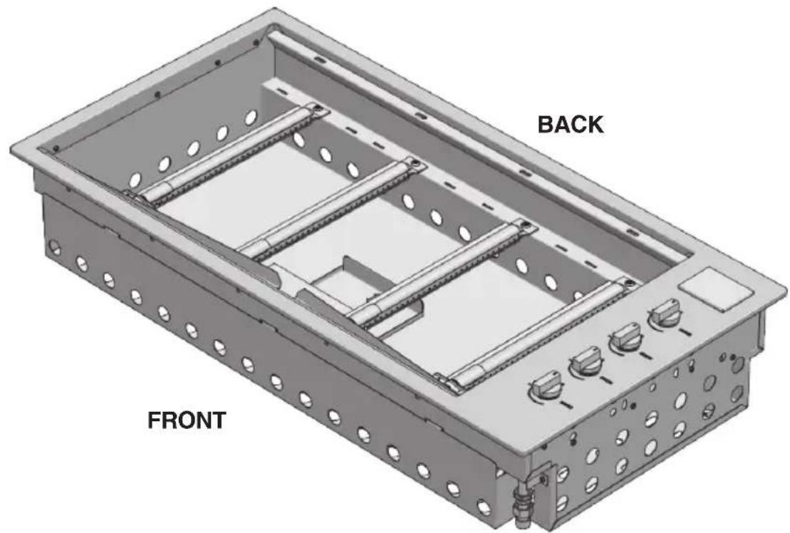
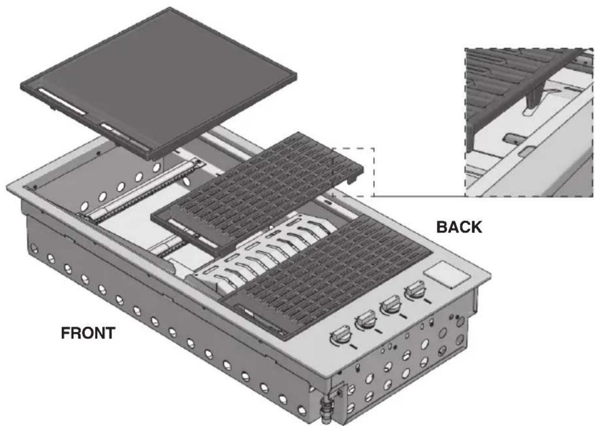
- Place the flame diffusers in the desired positions (under the points (A) in which the grill sections will be placed) and attach the rear edge of the flame diffuser to the rear of the body of the barbecue.
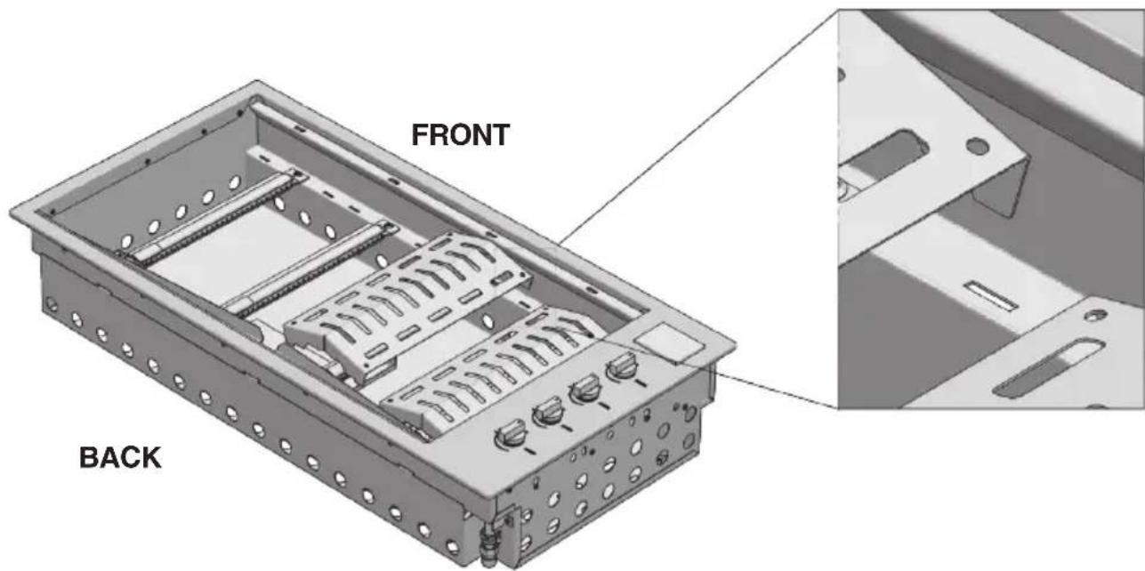
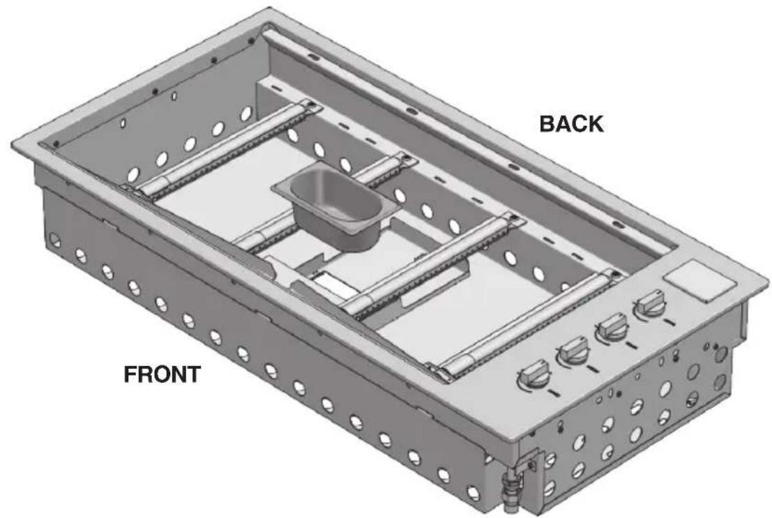
- Apply the oil drip pans to the front of the barbecue.

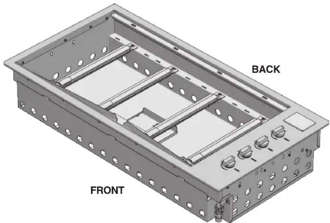
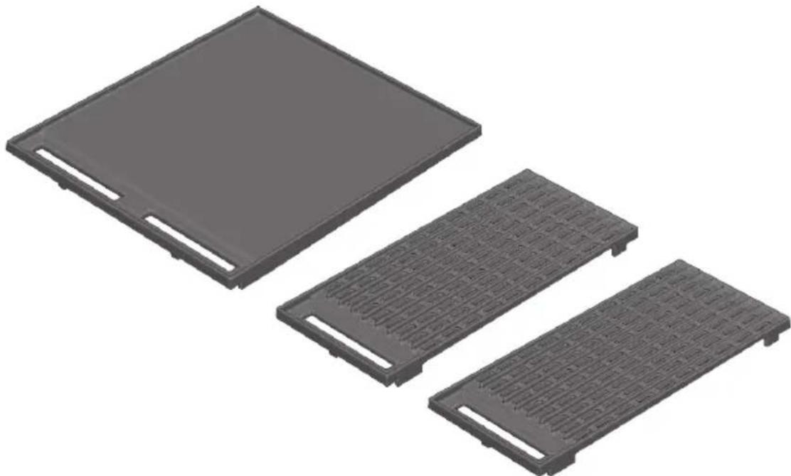
- Place the cooking plate and grill sections in the desired positions, making sure that the flame diffusers are under the grill sections.
NOTE: Make sure that the grill groups are correctly oriented so that the surface of the grill is tilted forward to allow the oil to drain into the drip pan.
natural_image
Three gray plastic heat exchanger or cooling unit panels with different internal structures (no text or symbols visible)
- After installation in the counter, connect the thin cover or cooking hood area as described in the chapter "Application of the thin cover or cooking hood" in this manual.
| GAS TYPE NATURAL GAS UNIVERSAL LPG | ||||||
| Model 100 80 60 100 80 60 | ||||||
| Nominal heat input (MJ/h) 52 39 26 52 | 39 26 | |||||
| Injector diameter (1/100mm) 170 170 1 | 70 100 1 | 00 100 | ||||
| Number of injectors 4 3 2 4 | 3 | 2 | ||||
| Pressure (kPa) 1 1 1 2,75 2,75 2,75 | ||||||
| Primary air regulation (mm) ☒ | 2 All open | |||||
Overall dimensions: 4 burner is 1000mm wide, 3 burner is 800mm wide, 2 burner is 600mm wide.
Adapting to different types of gas
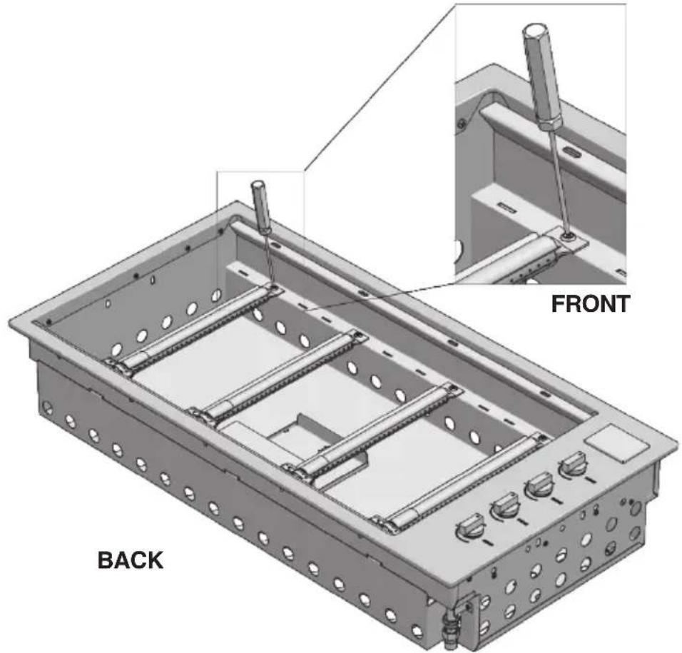
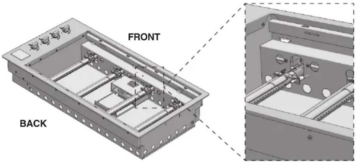
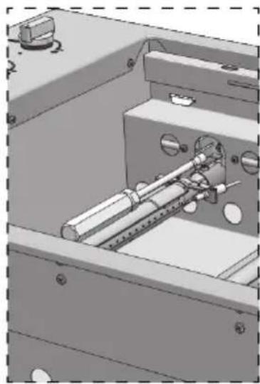
If the appliance is configured for a different type of gas than that available, you have to replace the injectors with ones corresponding to the type of gas to be used (see tables on the preceding pages). The replacement will be made using an adequate 7 mm key after having lowered the burners as in the following images. After replacing the injector, regulate the air to 1 mm for natural gas and to the maximum if LPG.
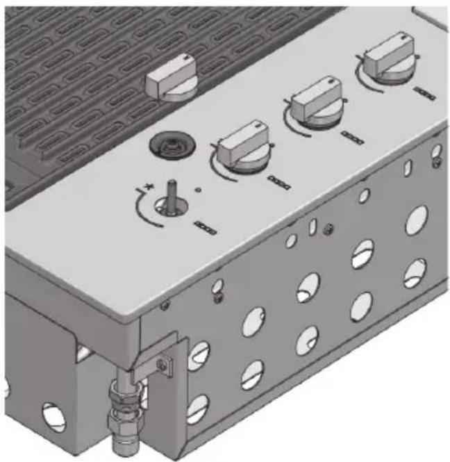
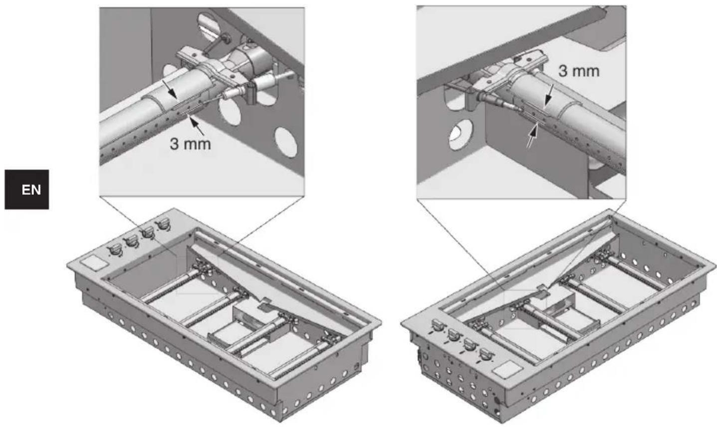
To adjust the minimum, after lighting the burner, remove the knob and the gasket below and rotate the screw of the tap (B - see page 70), which should be totally closed for LPG and opened about 3/4 turn for natural gas, keeping in mind that a flame lower than 3 mm may not even be “perceived” by the thermocouple of the tap. After regulating the minimums, replace the gaskets and knobs.
1 - Unscrew the fixing screws of the burner.
2 - Lower the burner and replace the injector.
EN
natural_image
Mechanical assembly diagram showing internal components with no visible text or symbols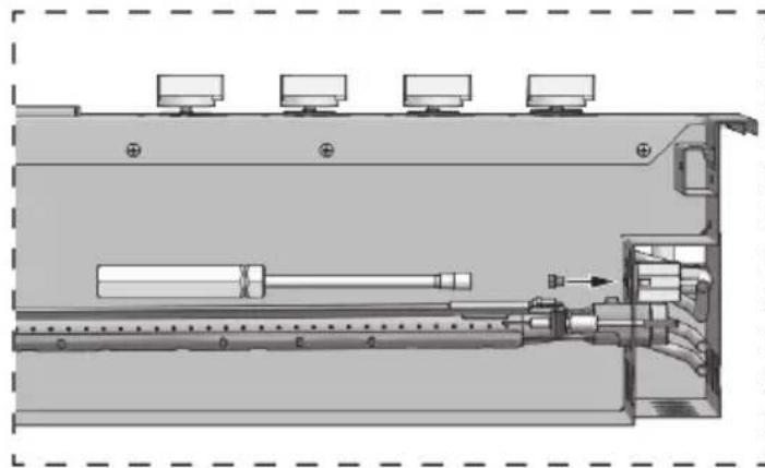
natural_image
Technical diagram of a mechanical assembly with no visible text or symbolsFRONT
NOTES
- The appliance MUST only be installed and serviced by qualified and authorized personnel.
- The product is exclusively intended for outdoor use.
- The product must be installed according to the instructions, which require ventilation openings to allow the grill to work properly. The lack of adequate ventilation to supply air to the appliance can lead to poor operation of the burners or excessive heat build-up in the installation compartment.
- The unit's ventilation openings must not be covered during installation.
EN
Gas connection
Refer to AS/NZS 5601 (Gas Installations) and following page for further details
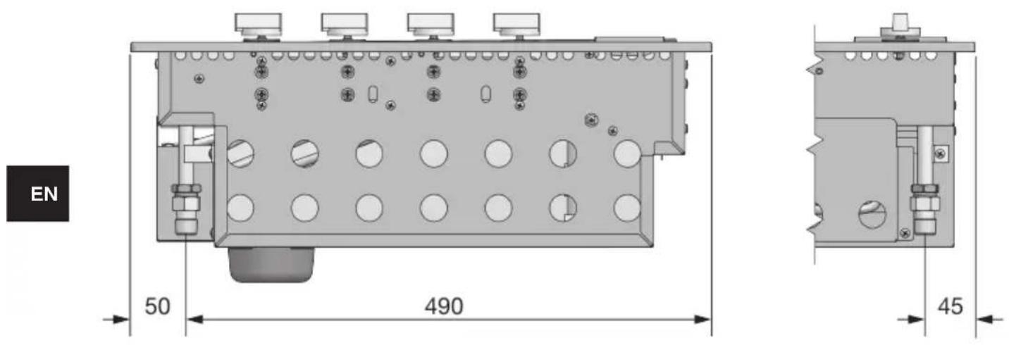
Connect the appliance to the cylinder or system according to the requirements of current law, making sure that the appliance is configured for the type of gas available. If not, see: "Adapting to different types of gas". Also check that the feed pressure falls within the values shown in the table: "Gas specifications".
Rigid and semi-rigid metal and rubber hose connections must be approved to AS/NZS 1869 for hose assemblies and AS 4631 for semi-rigid connectors for gas.
Make the hook-up with metal fittings and pipes (even flexible hoses) so as not to stress the components inside the appliance.
A rubber hose connection complies with current law only if the hose can be inspected along its entire length and easily replaced near the expiration indicated on the hose.
NOTE: - After installation, use soapy water to check the perfect seal of the entire connection system. DO NOT USE AN OPEN FLAME TO CHECK THE GAS SEAL.
Gas Connection
I. For connection to 9Kg portable gas cylinders please refer to page 28
II. For connection to a fixed LPG Supply: It is possible to connect this barbecue to a fixed LPG reticulated piping system which may supply gas to other appliances in the building. The installation must be carried out by a licenced gas fitter in accordance with AS/NZS 5601 and any relative Building Code/Statutory Regulations. The gas fitter must check the appliance data label to confirm the gas type prior to installation, ensure that the barbecue is operating correctly and show the customer how to operate the barbecue on completion of installation
III. For connection to a fixed natural gas supply: It is possible to connect this barbecue to a fixed natural gas piping reticulated system. The installation must be carried out by a licenced gas fitter in accordance with this instruction manual, AS/NZS 5601 and any relative Building Codes/Statutory Regulations. The gas fitter must check the appliance data label to confirm the gas type prior to installation, ensure that the barbecue is operating correctly and show the customer how to operate the barbecue on completion of the installation
Important notes relating to fixed installation barbecues
- For barbecues designed for built in fixed installation: please ensure that the clearances referred to on pages 26, 27, 28 & 29 of this manual are observed and adhered to
- For barbecue designed for built in fixed installation
I. Before each use remove any accumulated grease and other cooking residue
II. Check the hose & regulators, if they appear to be damaged in any way, have a licenced gas fitter replace them
Important notes relating to connection via portable LPG Cylinder
- For barbecues connected via 9Kg portable LPG cylinder: Should the cylinder be housed in a closed compartment under the barbecue, minimum free ventilation at high and low level of 20,000mm squared is required as per AS/NZS 5601 Appendix J Clause J3.4 (d) Please refer to pages 27, 28 & 29 of this manual for assistance
- For barbecues connected via 9Kg portable LPG cylinder: The barbecue is supplied with a hose and regulator already attached to the barbecue manifold
I. Attach the regulator end of the hose assembly to the LPG cylinder
II. Ensure that the valves on the barbecue are in the off position
III. Turn the cylinder valve on and apply a soapy water solution to all of the joints to ensure there are no gas leaks. If bubbles form at any of the joints this indicates a gas leak and the cylinder valve should be turned off and the joints tightened.
IV. If the gas leak persists, turn the cylinder valve off and contact an authorised installer/dealer for assistance
V. Never look for gas leaks with a naked flame
VI. Check the hose & regulator assembly on a regular basis and if found to be damaged, have it replaced. It is recommended that these components be replaced every five years
VII. Inspect the gas cylinder routinely to ensure the test date is not overdue. Cylinder should be re-tested and certified every 10 years
VIII. Before each use remove any accumulated grease & any other cooking residue
Universal LPG regulator and braided hose 1
AS/NZS 5601 (Gas Installations)
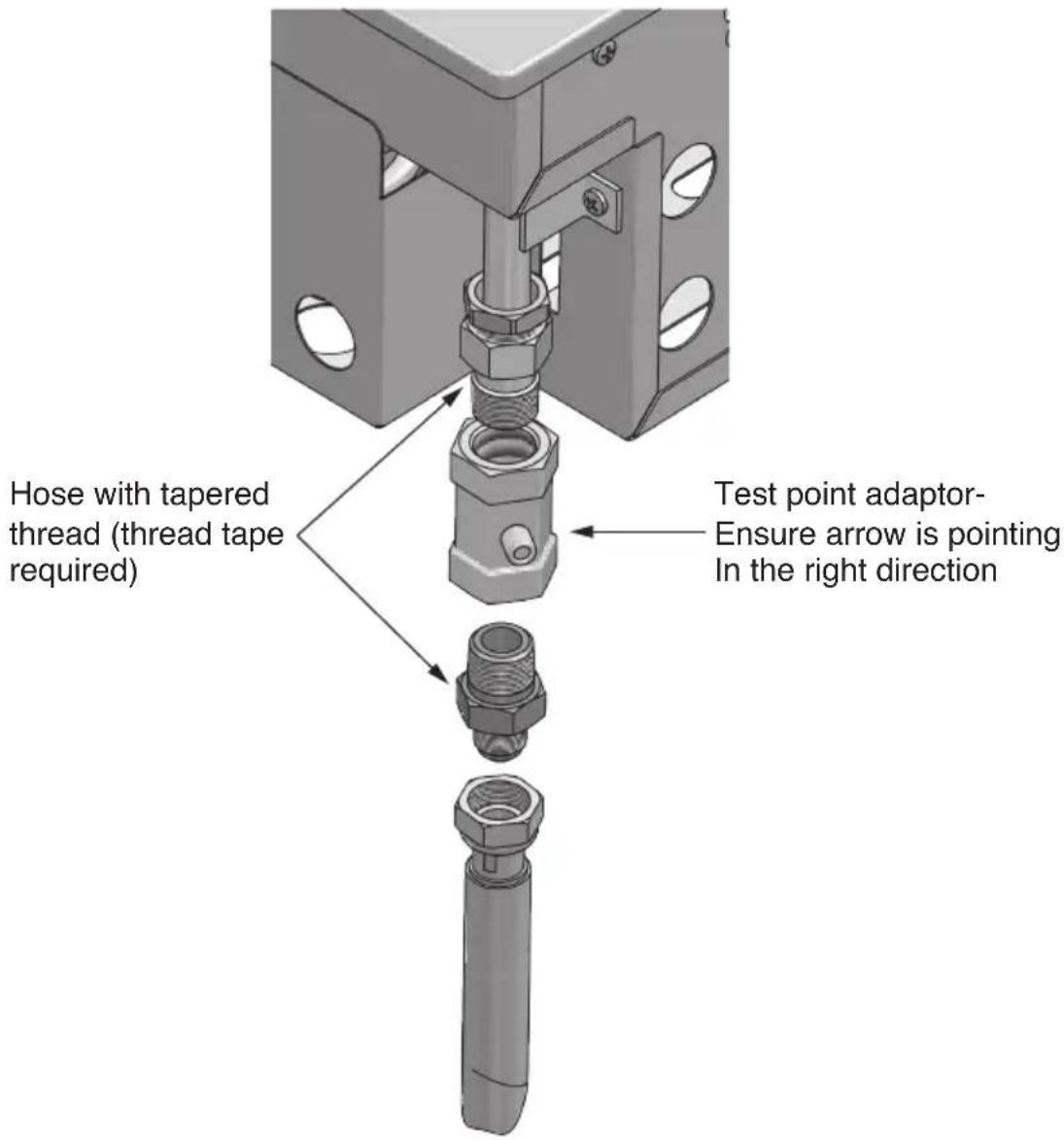
CONVERSION PROCEDURE
Normal LPG to NG
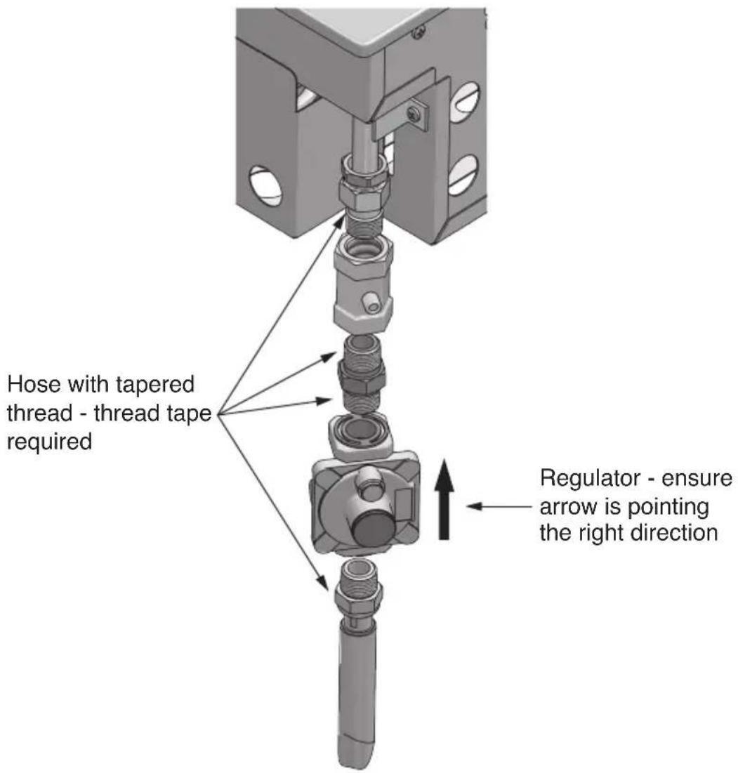
- Disconnect and disassembled/remove trivet, burners etc.
• Install the Natural gas regulator incorporating the test point pressure nipple. - Remove injectors and replace with correct sizes for each burner.
- Adjust aeration (X) per every burner
• Re-assemble burners. - Turn gas on and test for leaks, repair if necessary.
• Light the burners and set the pression to 1,00kPa. - Turn burner "Low" setting and adjust setting accordingly.
- Chek operation of ignition etc.
- Ensure data plate is changed with the new data plates supplied in the product.
For Natural Gas connection a bayonet connection point should be installed by a licensed gas fitter prior to installing the barbecue unit.

natural_image
3D technical illustration of a mechanical component with multiple rotary switches and perforated holes (no text or symbols)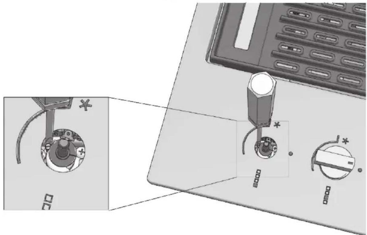
natural_image
Diagram showing a device with a rotary knob and a switch, alongside a close-up of its internal components (no text or symbols present)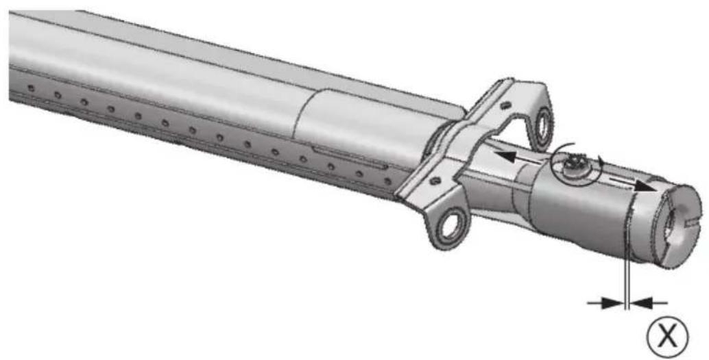
natural_image
Technical illustration of a mechanical assembly with no visible text or symbolsGas cylinder safety information
- When converted for the use of universal LPG, the appliance is designed to use different types of cylinders depending on the installation made. See the chapters on Installation Preparation and Connection of the cylinder.
- The gas cylinder must be manufactured and marked in accordance with the specifications for LPG cylinders.
- The shut-off valve must be closed when the appliance is not in use.
- The gas cylinders must be kept in an approved housing out of the reach of children.
- When you disconnect the gas cylinder, make sure all the control valves are in the "OFF" (O) position.
- Before disconnecting, remove the cylinder from any housing in which it may be located.
- When you reconnect the hose to the cylinder, make sure all the connections are tight before placing it back in its compartment.
• After each connection of a cylinder, perform a leak test as described below.
Leak testing procedure
- Make sure that all the gas taps are in the "OFF" (O) position.
- Mix a solution of water and detergent or soap in a small container.
• After connecting the hose, open the valve on the gas cylinder or gas system tap. - Using a brush, paint the solution on the gas connection points and check for bubbles.
- Bubbles indicate a leak.
- Close the valve and tighten the fitting, possibly inserting a new gasket. Repeat the leak test.
- If the leak persists, turn off the gas and contact an authorized gas system maintenance technician to repair the leak.
Installation instructions and warnings

ATTENTION

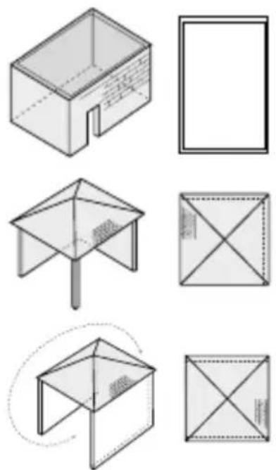
- The appliance must only be used above ground level, in open air and natural ventilation without stagnant areas where leaking gas and combustion products are rapidly dispersed by the wind or natural convection. This barbecue is designed exclusively for outdoor use. Refer to the drawings below.
- Never install the barbecue inside buildings, garages, sheds or covered walkways, or in a boat, camper or caravan. This prevents the creation of fires or carbon monoxide with toxic effects or asphyxiation.
- The compartment in which the appliance is installed must conform to one of the following requirements:
- A compartment with walls on all sides, but with at least one permanent opening at ground level and without upper cover.
- In a partial compartment that has a top cover and not more than two walls.
- In a partial compartment that has a top cover and not more than two walls; in this case, the following principle applies:
- At least 25% of the total area of the walls is completely open and at least 30% of the remaining area of the walls is open and free.
- In the case of balconies, at least 20% of the total area of the side, front and rear walls must be and remain open and free.
External surface area example 1
External surface area example 2
External surface area example 3
both ends open
External surface area example 4
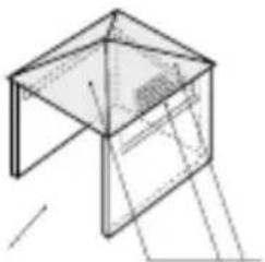
natural_image
Isometric line drawing of a simple geometric structure resembling a table or cage (no text or symbols)
open side for at least 25% of the total area of the walls
in total 30% or more of the remaining surface of the walls is open and free
EN
External surface area example 5
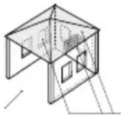
natural_image
Isometric line drawing of a 3D geometric structure resembling a tent or cage (no text or symbols)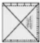
open side for at least 25% of the total area of the walls
in total 30% or more of the remaining surface of the walls is open and free
Selection of the point of installation
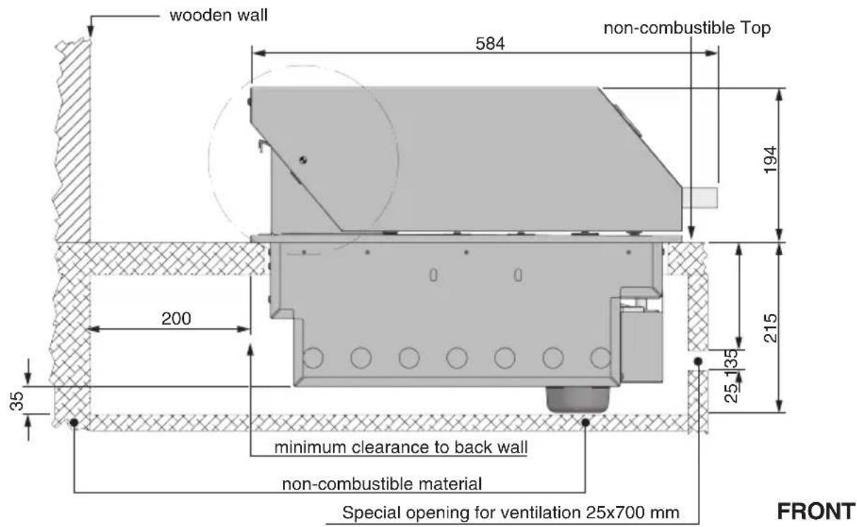
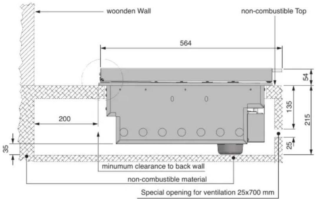
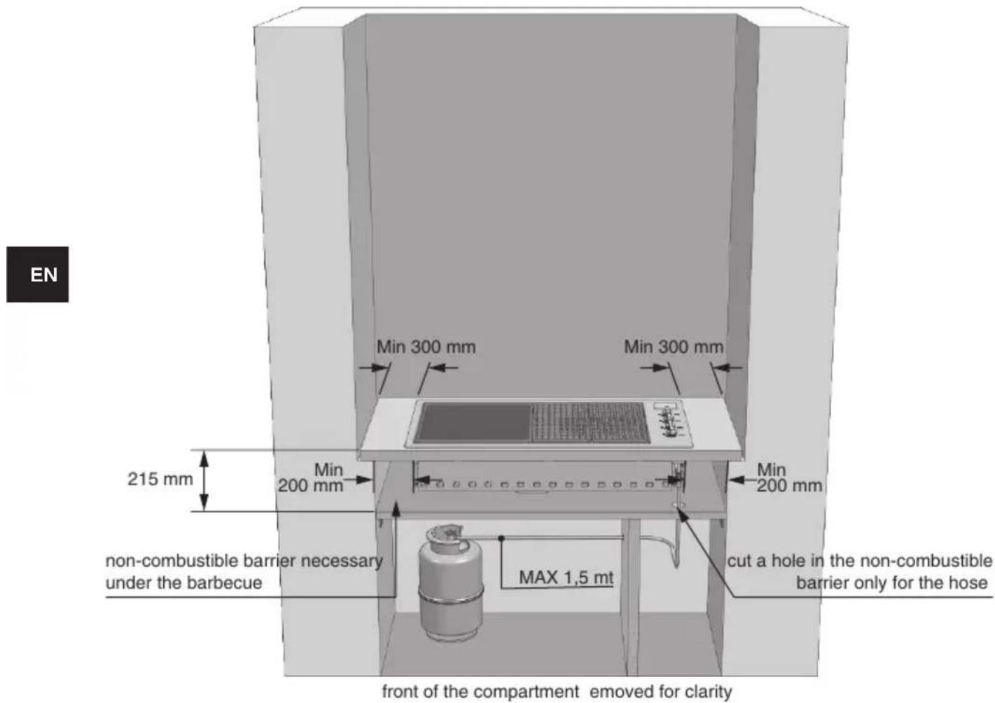
- The appliance must not be installed on combustible materials. The minimum distance from combustible materials is 600 mm overhead, 300 mm sides and 200 mm rear.
- The free space above the cooking surface with respect to combustible materials must be at least 600 mm.
- The appliance must be installed in accordance with standards and local deviations.
- When using LPG, ventilation must be ensured in the compartment. The gas is highly explosive and can cause serious personal injury and property damage if it is left to accumulate and then ignited.
- Avoid locations exposed to the wind as this may affect cooking and the efficiency of the burners. If you cannot avoid such a location, screens may be necessary.
Installation compartment
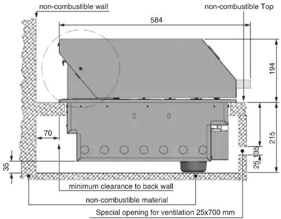
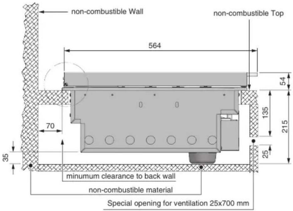
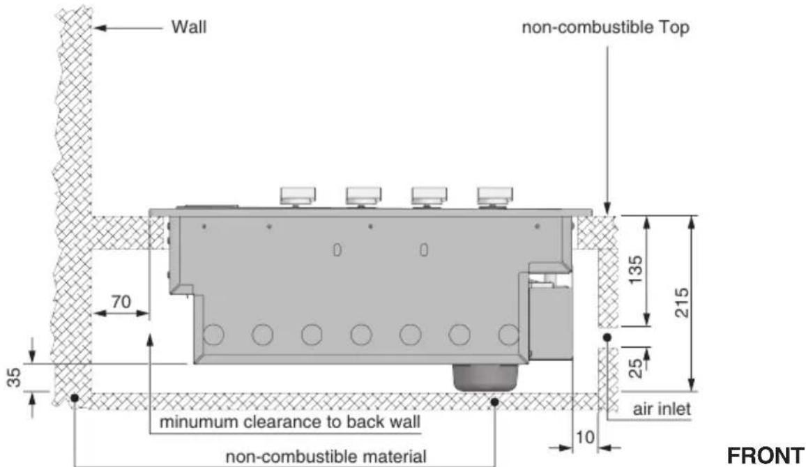
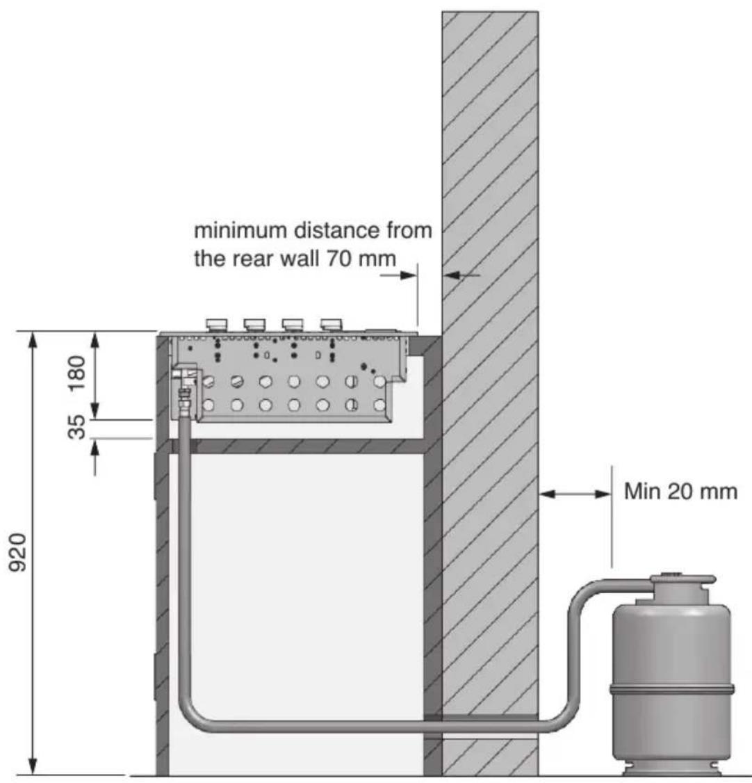
- The barbecue requires a non-combustible barrier beneath it to prevent reaching an excessive temperature. The panel that acts as a barrier must be positioned 30/35 mm below the base of the unit.
- The installation compartment must be made of non-combustible materials. Materials suitable for its construction include brick, granite, marble, Hardiplank® and Villaboard® on a metal or brick structure.
- The appliance requires ventilation openings in the front wall of the compartment. See the drawing on page 27 for details.
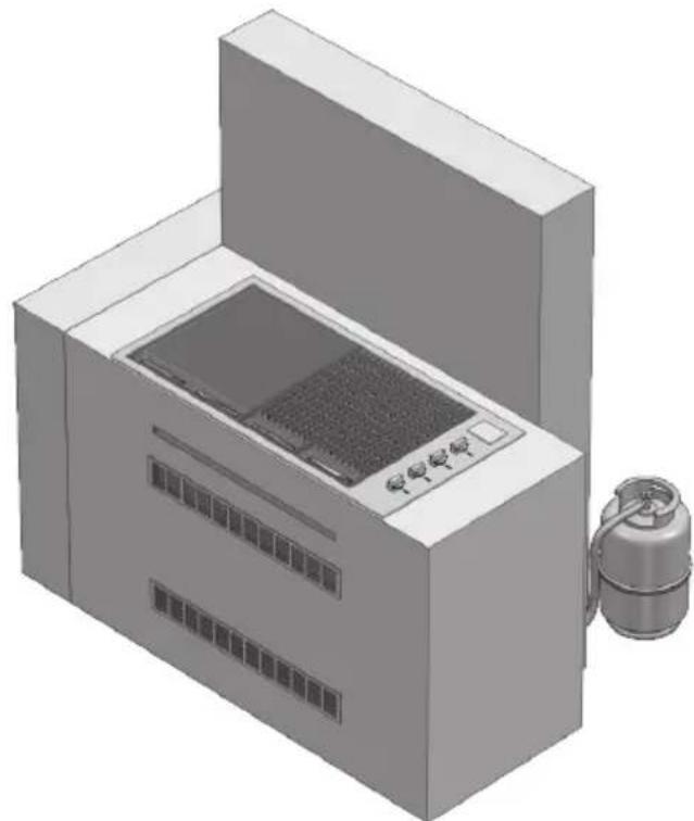
- The appliance unit can be mounted in an island counter or a counter with splash guard. Read the specific requirements for each type of mounting.
Island-mounted
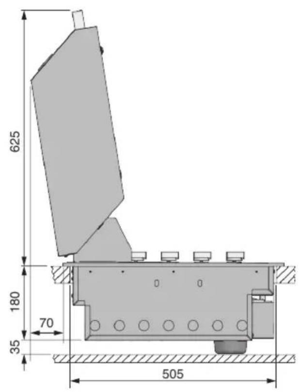
- If the appliance is installed in an island, it can be placed in the centre. Pay particular attention to the overall dimensions of the top of the island, taking into account the open cooking hood and its projection. See page 24.
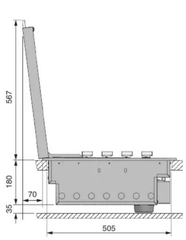
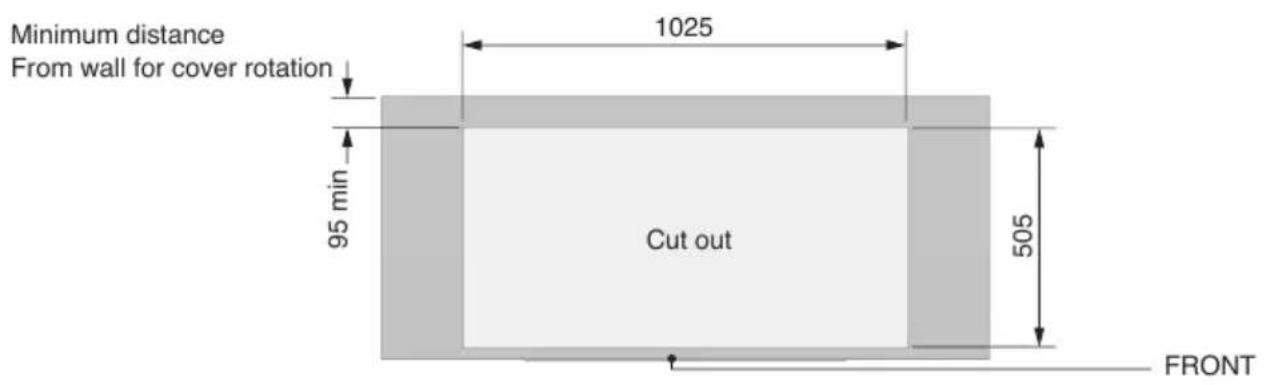
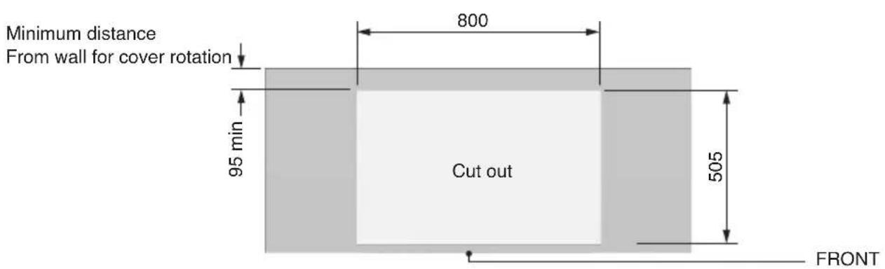
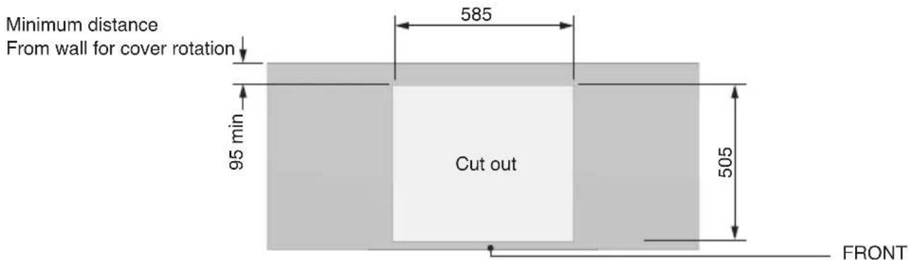
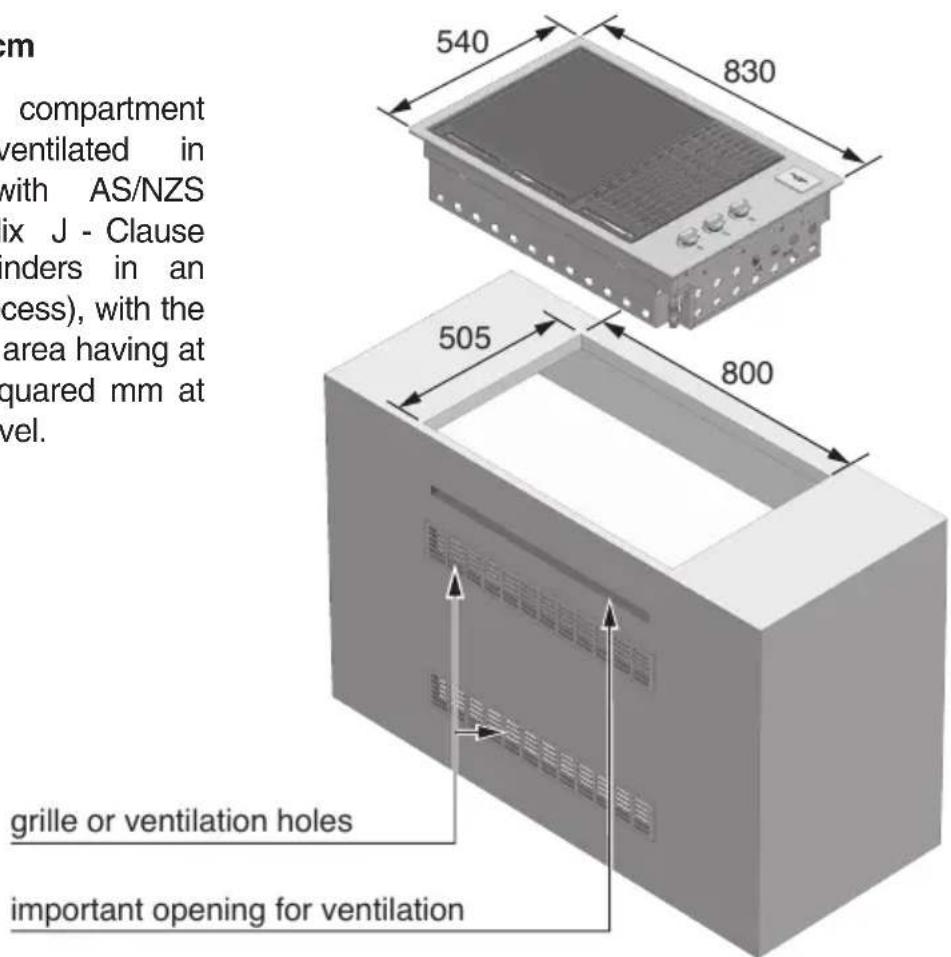
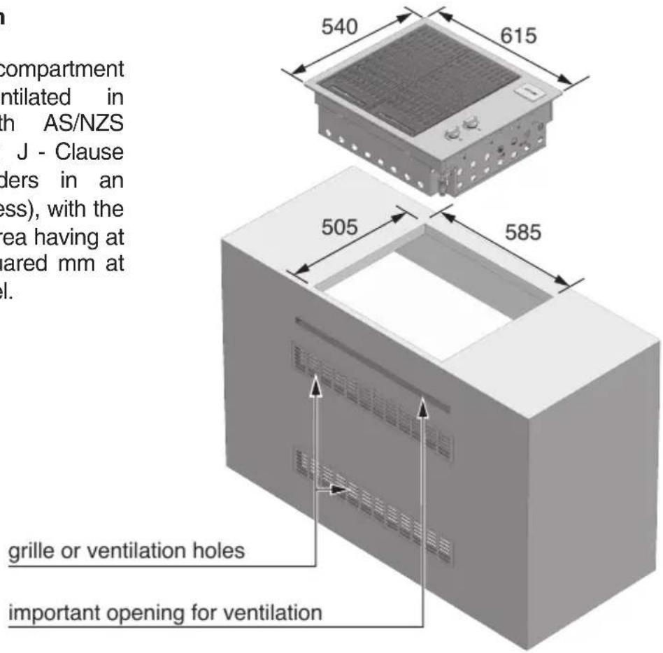
- The required dimensions of the cut-out are 1025 mm x 505 mm for model 100 cm, 800 mm x 505 mm for mod. 80 cm and 585 mm x 505 mm for mod. 60cm (see drawing pag. 26/27).
Installation in a counter in a special context
- The context must be made of non-combustible material.
- When mounting the appliance against a wall or a fence, it is essential to insulate combustible materials. All combustible materials must be kept at least 200 mm away from the barbecue.
- The required dimensions of the cut-out are 1025 mm x 505 mm for model 100cm, 800 mm x 505 mm for mod. 80 cm and 585 mm x 505mm for mod. 60cm (see drawing pag. 26/27).
- Models with high cooking cover require a specific free space on the back of the barbecue between the splash guard and the cut-out of the counter of at least 70 mm. This, so that the hood has the free space needed to open.
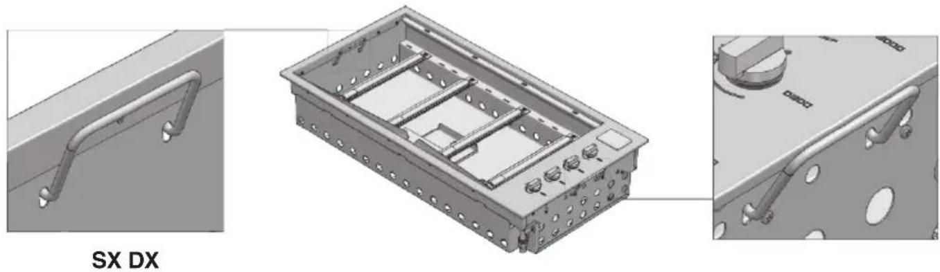
To facilitate insertion in the cabinet, the product has specific lifting handles (see figure below)
natural_image
3D CAD model of a mechanical housing component with mounting brackets and mounting holes, shown from three orthographic views (no text or symbols on the diagram itself)EN
FRONT
FRONT
FRONT

Mod BBQ 100 cm
Mod BBQ 80 cm

Mod BBQ 60 cm

ATTENTION
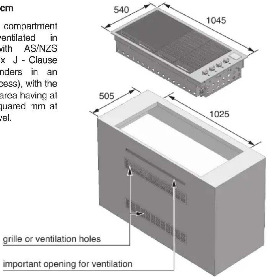
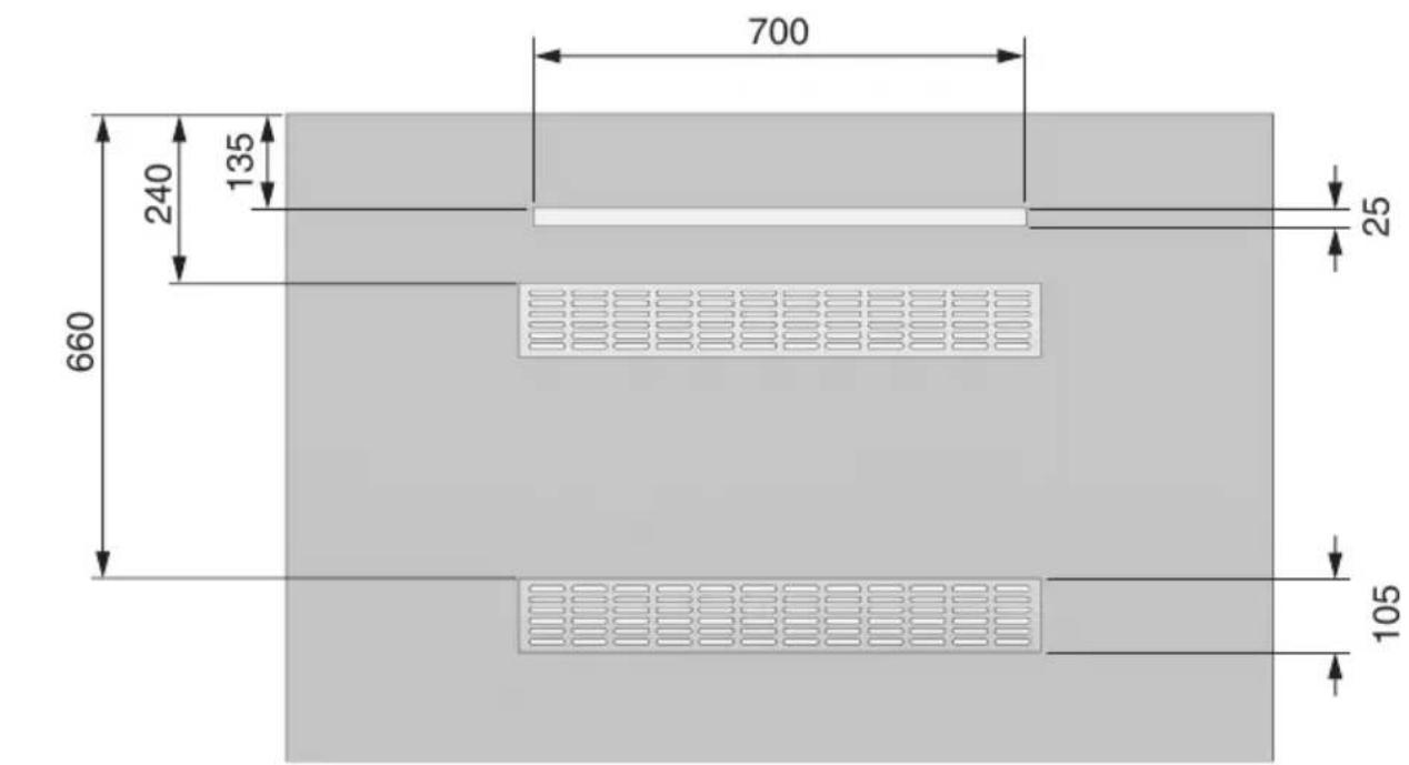
- The appliance requires adequate ventilation. An opening for ventilation must be provided as shown on the following pages. A ventilation grate can be applied, if desired. This ventilation surface allows air to enter the compartment for the optimum combustion. In case of an island construction, this opening can be at the rear of the island. The grille or ventilation holes are mandatory in the case of an LPG installation. LP gas is heavier than air; in the event of a leak, the vent allows the gas to escape from the compartment. The opening for ventilation must be at least 700 mm x 25 mm and placed in a central position 135 mm below the mounting surface. (See drawings on the following pages)
Mod BBQ 100 cm
The cylinder compartment must be ventilated in accordance with AS/NZS 5601, (Appendix J - Clause J3 - 4: Cylinders in an enclosure or recess), with the free ventilation area having at least 20,000 squared mm at high and low level.
EN
Mod BBQ 80 cm
The cylinder compartment must be ventilated in accordance with AS/NZS 5601, (Appendix J - Clause J3 - 4: Cylinders in an enclosure or recess), with the free ventilation area having at least 20,000 squared mm at high and low level.
Mod BBQ 60 cm
The cylinder compartment must be ventilated in accordance with AS/NZS 5601, (Appendix J - Clause J3 - 4: Cylinders in an enclosure or recess), with the free ventilation area having at least 20,000 squared mm at high and low level.
Island-mounted

ATTENTION
The compartment below the barbecue unit must be isolated from the barbecue by a non-combustible panel. The compartment must comply with the requirements of AS/NZS 5601. If the barbecue is fuelled by LPG, ventilation openings must be made at the top and bottom of the compartment or cavity as shown in the drawings on pages 28 and 29, each of which must provide a free surface of at least 200 cm2 per cylinder housed or 700cm2 as shown if the LPG gas cylinder is located elsewhere.
EN
natural_image
3D rendering of a laboratory or industrial machine with a lid and ventilation slots (no visible text or symbols)EN
The LPG cylinder may be connected inside the object-holder compartment of barbecue only if it has the dimensions shown in the guidelines. The safe use of a cylinder inside the object-holder compartment of the barbecue depends on several factors:
A) The base of the cylinder must be properly inserted between the plates and be horizontal on the base panel.
Dimensions of the cylinder
Max height 465 mm
Width 289 mm - (rectangular section) or 318 mm (circular section) maximum B) Capacity of the cylinder max 6 kg
There are several models of cylinders with approved dimensions (2).
WARNING: if the LPG cylinder purchased does not have the required dimensions, do not attempt to connect it inside the object-holder compartment. Fix the cylinder to the bracket or rest it on the floor. Failure to follow these instructions could damage the hose and cause fire or explosion, with serious injury or death and property damage.
EN
Application of the thin cover
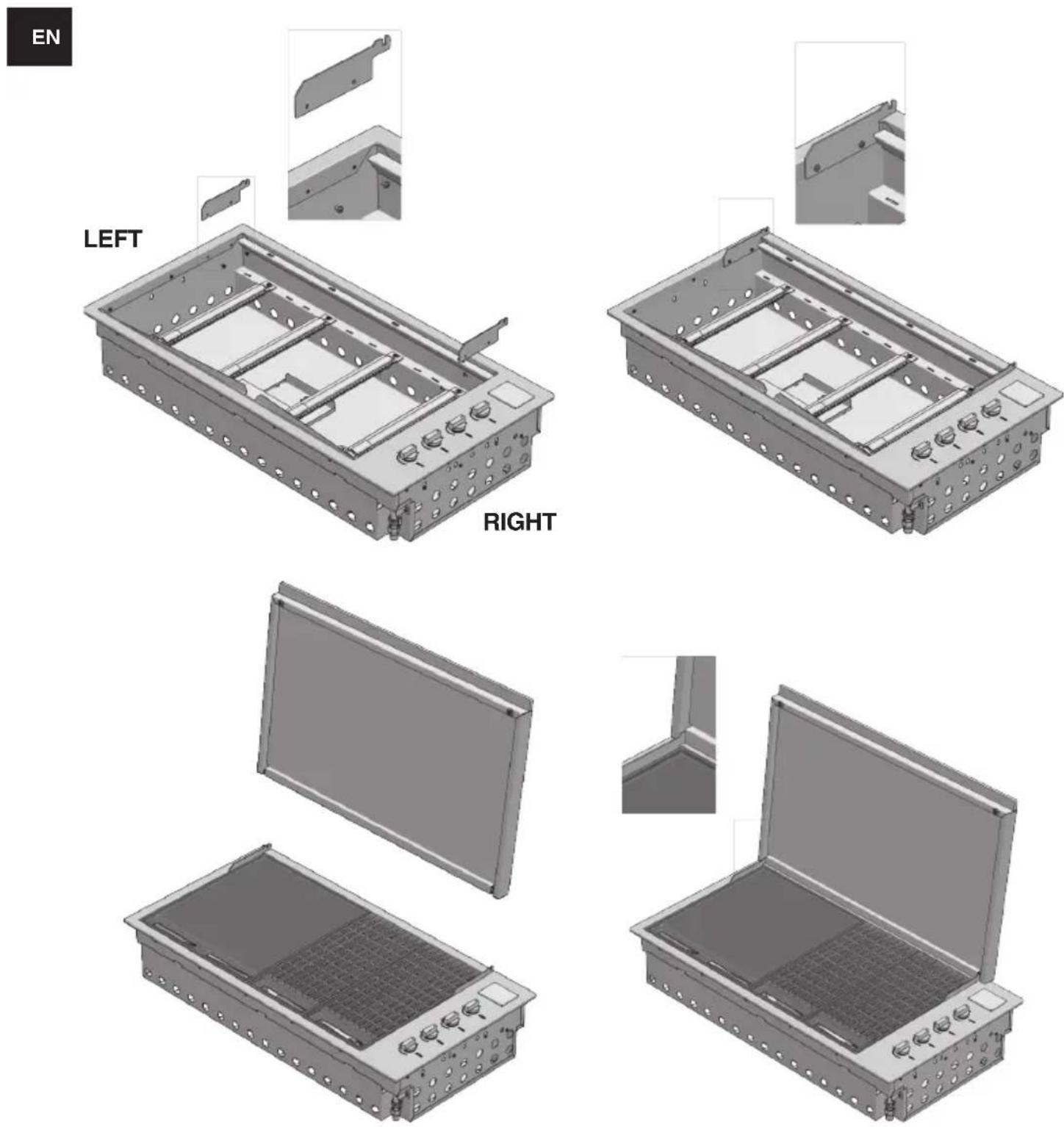
Application of the low cover
- Remove the thin cover from the packaging.
- Attach the hinges to the outer frame and secure it with the special screw provided.
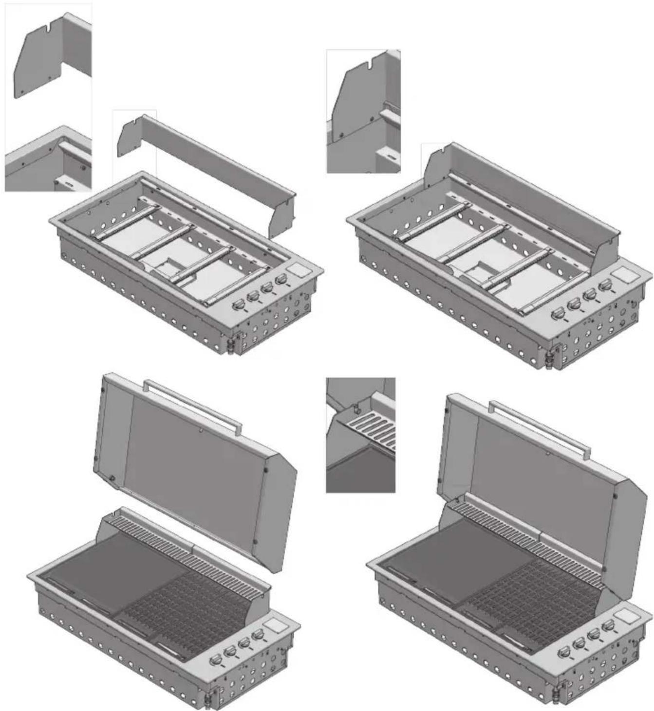
Application of the high cover
- Remove the High cover from the packaging.
- Remove the hinge from the cover and apply it to the outer frame. Fix it with the special screws provided.
- Insert the cover into the seats of the hinge.

IMPORTANT
• Given the dimensions of the cooking hood, we recommend that two people position it.
- During positioning the high cover group, take special care to avoid scratching the external profile.
natural_image
Technical illustration of a metal tray with open and closed compartments, showing internal structure and mounting features (no text or symbols)Usage instructions

IMPORTANT
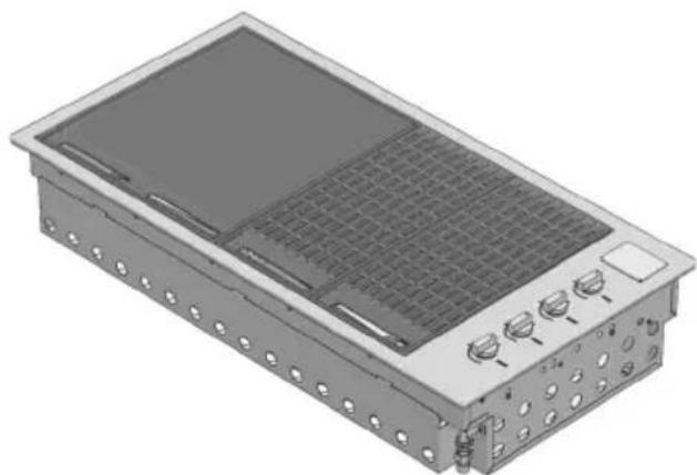
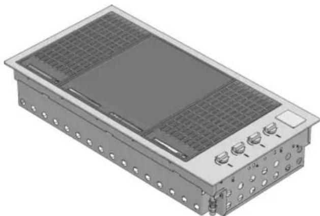
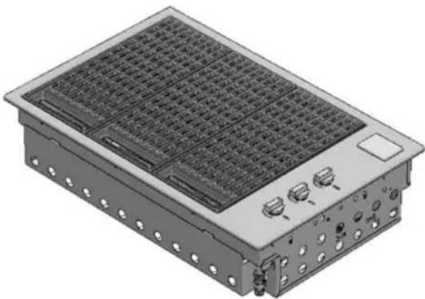
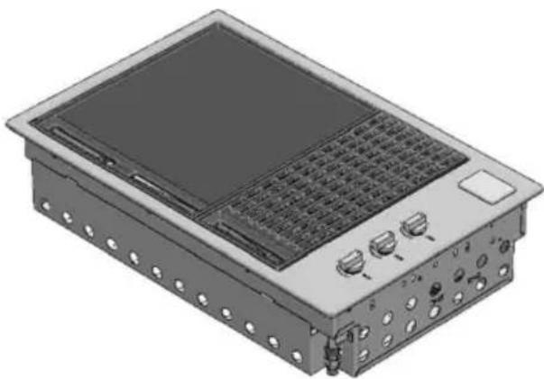
Make sure that the flame diffusers are positioned flame under the panels of the grills
natural_image
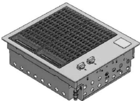
3D rendering of a rectangular electronic device with internal grid and mounting holes (no text or symbols visible)BBQ 100 Solid cooking plate on the left, double grill on the right - best orientation for grilling
natural_image
3D rendering of a rectangular electronic device with grid panels and control buttons (no text or symbols visible)BBQ 100 half grill on the left, central solid cooking plate, hal grill on the right - best orientation for roasting
natural_image
3D rendering of a modular electronic device with grid and control buttons (no text or symbols visible)BBQ 80 total grill
natural_image
3D rendering of a modular electronic device with ventilation grilles and control knobs (no text or symbols visible)BBQ 80 Solid cooking plate on the left, grill on the right - best orientation for grilling
natural_image
3D rendering of a modular electronic device with grid and mounting ports (no text or symbols visible)BBQ 60 total grill
Control functions
Before lighting the barbecue:
- Check that all the gas hoses and fittings are tight.
- Open the thin or high cover.
EN
Gas leakage detection test
Never use a match or flame, use soapy water solution and spray or brush the solution onto all connections. Carefully check for bubbles which indicate a gas leak. If leaks are detected, turn the gas off and retighten connection(s), then repeat test. The fittings must be thoroughly rinsed with clean water after testing.
NOTE: The thin cover is intended to protect against the weather. The cover is not intended to be used as a cooking hood.
- Make sure that all the control knobs are in the closed (O) position.
- Make sure that the cooking surfaces are clean.
- Open the main gas valve.
Ignition instructions
- Do not light the burners with the cooking surfaces covered.
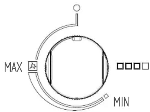
- To light a burner, press the knob and turn it to the "MAX" (fast pre-heating) position.
- Hold it for 5 seconds (count to 10), release it and check the flame from the slots in the front.
- If the burner is not lit, turn the knob to the closed (O) position. Allow the gas to disperse, and then repeat the ignition procedure.
Manual lighting
- If the automatic ignition system is not working, the barbecue can be lit manually.
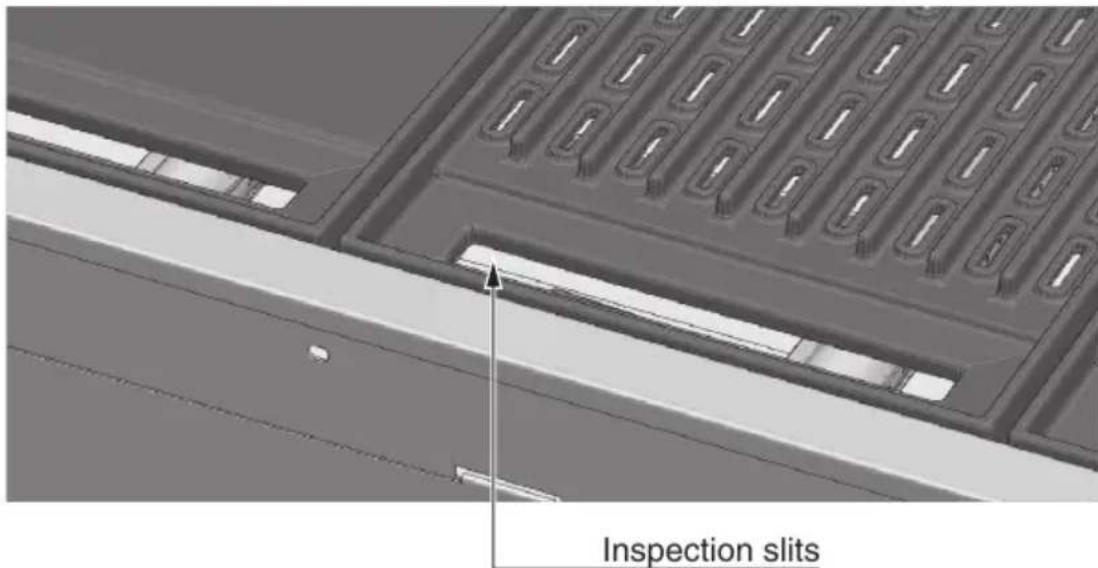
- To turn it on manually, use a long match (28cm). Pass the lit match between the inspection slots under the front part of the hob, approaching it to the burner, then turn the knob and hold it pressed on MAX (quick preheating) in order to perform the ignition. If it does not light, close the control valve and wait a few minutes for the gas to disperse before trying to light the barbecue again.
- Once one burner is lit, repeat the procedure for the others, if necessary.
- Incorrect lighting of the barbecue can result in serious injury, fire, explosion or death. If the burner does not light, turn the gas off, wait 5 minutes to allow the gas to disperse before attempting to light appliance again.
Pre-heating cooking areas
- The barbecue is equipped with high-power burners. Under most conditions, it will only be necessary to pre-heat the barbecue for just 5 minutes before starting to cook.
- As with most things, experience will teach the user the effectiveness and interval necessary for reaching the best pre-heating time for obtaining the ideal cooking temperature. Don't forget that this also depends on the type of food, its thickness and how you want to cook it.
- Tests have shown that you can reduce the heat of the burners for satisfactory cooking.
- If the barbecue has a thin cover, you should remove it in the presence of wind.
- If the appliance is not working properly, refer to the chapter "Troubleshooting".
- If you let the cooking areas overheat, there will be excessive smoke during cooking and the food will burn.
-
While cooking, avoid leaning over the open grill or placing the hands or fingers on the edge of the oven.
-
In case of uncontrolled sudden flames, remove the food from the fire until the flame is damped.
- To roast with the high cover closed, it is sufficient to adjust the 4 burners to the minimum power (MIN) for satisfactory cooking
EN
To turn off the burner
- When done cooking, turn the knob fully clockwise so that the mark on the knob is in the closed (O) position.

Remember to always close the valve of the gas cylinder after use.

Remember to shut-off the gas before closing the cover.
natural_image
3D rendering of an open industrial electrical enclosure with internal grating and mounting brackets (no text or symbols)
ATTENTION
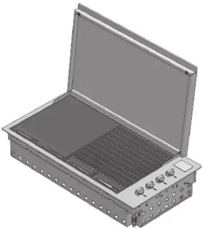
THE COVER MUST NOT BE CLOSED WHEN THE BURNERS ARE LIT.
If the cover is closed while the burners are lit, the cover and barbecue can be discoloured and damaged.
Cleaning and care
Care and cleaning of the appliance
To preserve its appearance, we recommend cleaning the cooking surfaces after each use. Where the unit is exposed to the elements, we strongly recommend the optional cover. Other surfaces must be maintained regularly to protect the unit from tea staining and rusting.

ATTENTION
Make sure the barbecue is turned off and has cooled down before executing the instructions shown below.
Cleaning of cooking parts
- Remove from the grill and from the cooking burners all the solid materials and the excess grease using a scraper or a metal brush with brass bristles
- Use a clean, dry cloth to make sure all surfaces are dry.
Other stainless steel surfaces

WARNING
Do not use caustic or abrasive detergents, steel wool or metal scrapers on these stainless steel surfaces because they can scratch and permanently damage the barbecue.
- Wash all stainless steel parts, including the thin cover, high cover and control knobs, with a soft cloth and warm soapy water
- Clean the surfaces, making sure to rub/dry in the direction of the grain in order not to damage the stainless steel.
- The inside of the barbecue can be cleaned with a soft cloth soaked in warm soapy water. The front panel/tray placed inside can be removed for an easy cleaning.
- Use a clean, dry cloth to make sure all surfaces are dry.
- VERY IMPORTANT! After drying, finish off the process with 3M™ Stainless Steel Cleaner and Polish or similar product in order to protect the stainless steel surface from corrosion and give it a polished shine.
Cleaning the cooking grills made of cast iron
- Clean with an adequate brass bristle brush. If necessary, remove from barbecue, wash with warm soapy water, rinse with water and dry carefully.
Important: After cooking and cleaning, the cast-iron grids should be oiled. Apply a thin layer of vegetable oil using a cloth or brush. Afterwards, use a cloth to rub the cookware as if you want clean the oil you just placed on it.

WARNING
Pay particular attention (especially when cleaning the knobs and around the knobs) to avoid water and soap residue from entering the control panel containing the valves or in the burners. Also, be careful not to touch the ignition electrode and thermocouple. There must be 3 mm of space between the electrode and the burners (see drawing on the next page). If the unit is exposed to the elements we recommend you use the optional vinyl cover.
Cleaning the grease drip pan
The integrated barbecue has a unique oil management system that uses overlapping channels to convey all the oil towards the front to easily removable drip pans, which must be cleaned after each use.
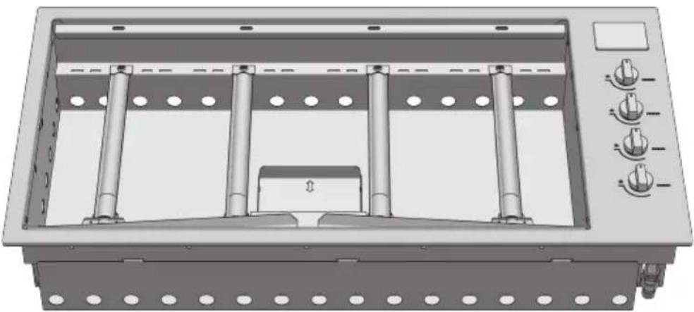
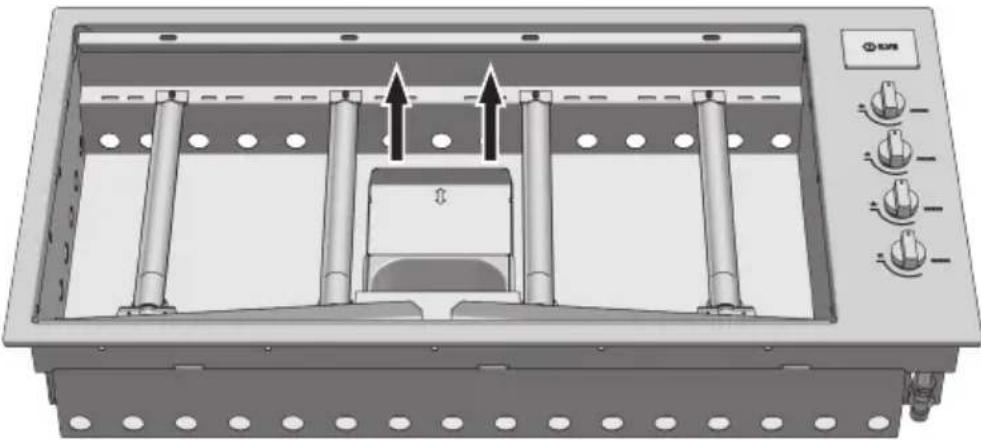
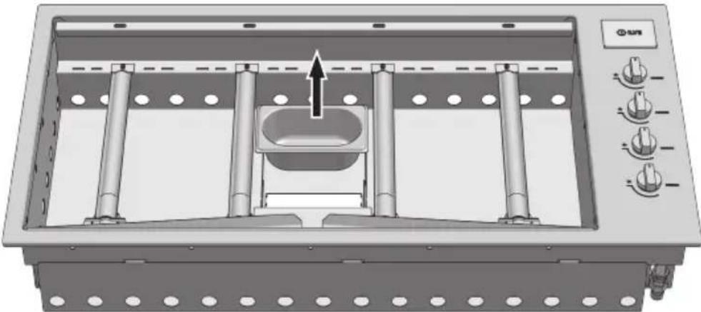
- To remove the drip pan, pull them upwards from the front of the barbecue; dispose of their contents in a responsible way. Wash the collection pans in hot soapy water or, if you want, you can put them in the dishwasher.
1 - To remove the drip pan
natural_image
3D rendering of a mechanical device with multiple cylindrical components and control knobs (no text or symbols visible)2 - Move the drawer
natural_image
Technical diagram of a mechanical device with multiple cylindrical components and directional arrows indicating movement or assembly (no text or symbols present)3 - Raise up the pan up
natural_image
3D rendering of a mechanical device with cylindrical components and a central housing, no visible text or symbolsBurners
The burners should be checked at least once a year and cleaned if necessary. Inspect the burners to make sure that no residue deposits and that the gas connections are free.

SUGGESTIONS AND INFORMATION
Special note on "tea staining"
Sometimes stainless steel surfaces are affected by a colour change called “tea staining”. This usually occurs in areas where high heat is used and can be removed using stainless steel cleaning agents. For best results, we recommend that you regularly use stainless steel cleaner on all stainless steel parts. These cleaners are available in all hardware stores and supermarkets.

Maintenance
Ignition system
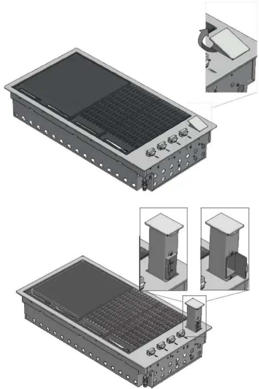
To change the battery, remove the battery cover by lifting the battery holder flap on the left side and pull out the battery. Replace it with a new D battery and replace the cover. Perform a test by pressing the knob; you should hear a click.

natural_image
Technical illustration of a modular electronic device with labeled components and internal structure (no text or symbols)Ventilation openings
The ventilation openings of the installation compartment must be inspected before each use of the appliance to make sure that there are no obstructions that could impede the free flow of air.
Troubleshooting
| PROBLEM POSSIBLE CAUSE SOLUTION | ||
| The barbecue doesn't light No gas | Check that the shut-off valve is open (ON) | |
| The ignition system is not working | Check the battery - you should hear a clicking sound when you press the knob | |
| Replace the battery | ||
| Light the barbecue manually | ||
| Gas tap regulated too high Clean | and delicately dry the electrode making sure that its position is correct | |
| Excessive smoke from the cooking surface | Gas valve set too high Lower the | gas or turn off some of the burners |
| Odour of gasDON NOT TRY TO LIGHT THE APPLIANCE | Gas leak Close the gas with the sh | ut-off valves |
| Check for leaks, tighten the fittings | ||
| If the problem persists, call the Service Centre | ||
For service enquires please contact us at customercare@eurolinx.com.au or 1300 85 64 11


MANUFACTURER'S DECLARATION
The manufacturer declares that, depending on their type, the products in this catalogue conform to the fundamental requirements of European Directives and, for this reason, the product bears the CE mark, for which this declaration of conformity was issued and made available to market supervisory bodies.
DISPOSAL OF USED APPLIANCES
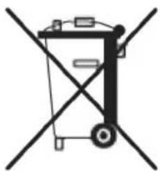
At the end of their useful life, these appliances may not be disposed of with normal urban waste but must be given to an electronic and electrical equipment collection and recycling point. This is indicated by the symbol shown on the product, in the instruction manual or on the packing materials.
The materials used in this appliance can be reused in conformity with their intended use. Thanks to the reuse, recycling or other forms of recovery of unusable appliances, you will make a contribution to protecting our natural environment.
You can obtain information about the disposal points for unusable appliances from your local authorities.
natural_image
Symbol of a trash bin crossed out by two diagonal lines (no text or labels)The manufacturer will not be liable for inaccuracies in this manual due to typographic errors. We reserve the right to make improvements or indispensable modifications to products without altering their essential specifications. Products can be modified following requests for improvements and CE standards.

ARTUSI
THE ART OF LIVING
Worldwide Appliances Pty Limited
A.B.N. 45868077422
Office:
48-50 Moore Street, Leichhardt N.S.W 2040
Post:
Locked Bag 3000, Annandale, N.S.W 2038
P: 1300 694 583
WARRANTY REGISTRATION
Your ongoing satisfaction with your artusi product is important to us. We ask that you complete the enclosed Warranty Registration Card and return it to us so that we have a record of the artusi product purchased by you.
PRIVACY
Worldwide Appliances respects your privacy and is committed to handling your personal information in accordance with the National Privacy Principles and the Privacy Act 1988 (Cth). A copy of the Worldwide Appliances Privacy Policy is available at www.artusi.com.au. Worldwide Appliances will not disclose any personal information set out in the Warranty Registration Card (“Personal Information”) without your consent unless required by:
-
law;
-
any Worldwide Appliances related company;
-
any service provider which provide services to artusi or assist artusi in providing services (including repair and warranty services) to customers. Our purpose in collecting the Personal Information is
to keep a record of the artusi product purchased by you, in order to provide a better warranty service to you in the unlikely event that there is a problem with your artusi product. Worldwide Appliances may contact you at any one or more of the address, email address or telephone numbers set out in the Warranty Registration Card. Please contact artusi on 1300 694 583 should you not wish to be contacted by Worldwide Appliances.
WARRANTY
1. Warranty
Worldwide Appliances warrants that each artusi product will remain, for a period of either 12 months or 24 months of warranty. All Warranties are valid from the original date of purchase, And warranty claims must be accompanied by the proof of purchase.
24 months warranty products:
All Built-in Appliances – Limited to Ovens, Gas, Induction and Electric Cooktops, and All Rangehoods
Freestanding Cookers - Gas and Electric Models (900mm Width)
Dishwashers - Freestanding, Fully Integrated, Semi Integrated and built-in
12 months warranty products:
Freestanding Cookers - Gas and Electric Models in 50cm, 54cm and 60cm Widths
Portable Appliances* – Benchtop Models and Portable Gas Models
- What is not Covered by the Warranty.
The Warranty does not apply if an artusi product is defective by a factor other than a defect arising in the manufacture of the artusi product, including but not limited to:
(a) damage through misuse (including failure to maintain, service or use with proper care), neglect, accident or ordinary wear and tear (including deterioration of parts and accessories and glass breakage);
(b) use for purpose for which the artusi product was not sold or designed;
(c) use or installation which is not in accordance with any specified instructions for use or installation;
(d) use or operation after a defect has occurred or been discovered;
(e) damage through freight, transportation or handling in transit (other than when Worldwide Appliances is responsible);
(f) damage through exposure to chemicals, dusts, residues, excessive voltage, heat, atmospheric conditions or other forces or environmental factors outside the control or Worldwide Appliances;
(g) repair, modification or tampering by the purchaser or any person other than Worldwide Appliances, an employee of Worldwide Appliances or an authorised artusi service contractor ^* ;
(h) use of parts, components or accessories which have not been supplied or specifically approved by artusi.
(i) damage to surface coatings caused by cleaning or maintenance using products not recommended in the artusi product handbook provided to the purchaser upon purchase of the artusi product; (j) damage to the base of an electric oven due to items having been placed on the base of the oven cavity or covering the base, such as aluminium foil (this impedes the transfer of heat from the element to the oven cavity and can result in irreparable damage); or
(k) damages, dents or other cosmetic imperfections not affecting the performance of the artusi in respect of an artusi product purchased as a “factory second” or from display
The Warranty does not extend to light globes used in artusi products.
- Domestic Use
Each artusi product is made for domestic use. This Warranty may not extend to artusi products used for commercial purposes.
4. Time for Claim under the Warranty
You must make any claim under this Warranty within twenty eight (28) days after the occurrence of an event which gives rise to a claim pursuant to the Warranty, by booking a service call on the telephone number below.
5. Proof of Purchase
Customers must retain proof of purchase in order to be eligible to make a warranty claim in respect of an artusi product.
6. Claiming under the Warranty
Customers will bear the cost of claiming under this Warranty unless Worldwide Appliances determines the expenses are reasonable, in which case the customer must claim those expenses by providing written evidence of each expense to Worldwide Appliances at the address on the Warranty Registration Card.
7. Statutory Rights
(a) These terms and conditions do not affect your statutory rights.
(b) The limitations on the Warranty set out in this document do not exclude or limit the application of the consumer guarantees set out in the Act or any other equivalent or corresponding legislation in the relevant jurisdiction where to do so would:
(i) contravene the law of the relevant jurisdiction; or
(ii) cause any part of the Warranty to be void.
(c) Worldwide Appliances excludes indirect or consequential loss of any kind (including, without limitation, loss of use of the artusi product) and (other than expressly provided for in these terms and conditions) subject to all terms,
conditions and warranties implied by custom, the general law, the Act or other statute.
(d) The liability of Worldwide Appliances to you
Warranty Card tear off
for a breach of any express or non-excludable implied term, condition or warranty is limited at the option of Worldwide Appliances to:
(i) replacing or repairing the defective part of the artusi product;
(ii) paying the cost of replacing or repairing the defective part of the artusi product;
(iii) replacing the artusi product; or
(iv) paying the cost of replacing the artusi product.
(e) Our goods come with guarantees that cannot be excluded under the Australian Consumer Law. You are entitled to a replacement or refund for a major failure and for compensation for any other reasonably foreseeable loss or damage. You are also entitled to have the goods repaired or replaced if the goods fail to be of acceptable quality and the failure does not amount to a major failure.
8. Defects
Any part of an artusi product deemed to be defective and replaced by Worldwide Appliances is the property of Worldwide Appliances.
Worldwide Appliances reserves the right to inspect and test artusi products in order to determine the extent of any defect and the validity of a claim under the Warranty.
*To locate your closest artusi authorised service agent please contact us on 1300 652 100 or visit www.artusi.com.au
ALL SERVICE CALLS MUST BE BOOKED
THROUGH AN AUTHORISED DEALER OR
WARRANTY DEPARTMENT ON 1300 652 100
OR stokesaps.com.au/artusi-service
0103201.

ARTUSI
THE ART OF LIVING
WARRANTY REGISTRATION CARD 01052013
Please complete and send to ARTUSI at:
REPLY PAID 83617
LEICHHARDT NSW 2040
| Last Name: First Name: | ||
| Address: | ||
| State: Postcode: Email: | ||
| Home Phone: Mobile: | ||
| Purchase Date: / / (Please attach proof of purchase to validate warranty) | ||
| MODEL NUMBER | SERIAL NUMBER(if you cannot locate the serial number please call ARTUSI on 1300 694 583) |
| 1 | |
| 2 | |
| 3 | |
| 4 |

ARTUSI
THE ART OF COOKING
DISCLAIMER
Worldwide Appliances PTY LTD, trading as ARTUSI, is continually seeking ways to improve the design specifications, aesthetics and production techniques of its products. As a result alterations to our products and designs take place continually. Whilst every effort is made to produce information and literature that is up to date, this brochure should not be regarded as an infallible guide to the current specifications, nor does it constitute an offer for the sale of any particular product. Product dimensions indicated in our literature is indicative only. Actual product only should be used to define dimension cutouts. Distributors, and retailers are not agents of ARTUSI and are not authorised to bind ARTUSI by any express or implied undertaking or representation.
ARTUSI OFFICES ARE OPEN DAILY FROM 9AM-5PM AND SATURDAYS 10AM-4PM
NSW & ACT (HEAD OFFICE)
48-50 MOORE STREET
LEICHHARDT
FO285694699
VIC, TAS & SA
1211 TOORAK ROAD
CAMBERWELL
FO398092155
OLD
1/42 CAVENDISH ROAD
COORPAROO
FO733970850
WA&NT
UNIT 10/55 HOWE STREET
OSBORNE PARK
F0892019188
NZ
PO BOX 11.160
SOCKBURN CHRISTCHURCH
F033445906
- Congratulations
- Contents
- Suggestion for the environment
- Disposal information for users
- Product description
- Integrated barbecue with thin cover
- Integrated barbecue high cover
- Components
- DESCRIPTION QTY
- CONFIGURATION 1
- CONFIGURATION 2
- Important safety instructions
- ATTENTION
- WARNING
- TIPS AND INFORMATION
- The manufacturer's liability:
- Assembling the barbecue
- Tools needed for assembly:
- Adapting to different types of gas
- NOTES
- EN
- Gas connection
- Refer to AS/NZS 5601 (Gas Installations) and following page for further details
- Rigid and semi-rigid metal and rubber hose connections must be approved to AS/NZS 1869 for hose assemblies and AS 4631 for semi-rigid connectors for gas.
- Important notes relating to fixed installation barbecues
- Important notes relating to connection via portable LPG Cylinder
- Universal LPG regulator and braided hose 1
- CONVERSION PROCEDURE
- Normal LPG to NG
- Gas cylinder safety information
- Leak testing procedure
- Installation instructions and warnings
- Selection of the point of installation
- Installation compartment
- Island-mounted
- Installation in a counter in a special context
- Mod BBQ 60 cm
- Mod BBQ 100 cm
- Mod BBQ 80 cm
- Dimensions of the cylinder
- Application of the thin cover
- Application of the low cover
- Application of the high cover
- IMPORTANT
- Usage instructions
- Control functions
- Gas leakage detection test
- Ignition instructions
- Manual lighting
- Pre-heating cooking areas
- To turn off the burner
- Cleaning and care
- Care and cleaning of the appliance
- Cleaning of cooking parts
- Other stainless steel surfaces
- Cleaning the cooking grills made of cast iron
- Cleaning the grease drip pan
- - To remove the drip pan
- - Move the drawer
- - Raise up the pan up
- Burners
- SUGGESTIONS AND INFORMATION
- Special note on "tea staining"
- Maintenance
- Ignition system
- Ventilation openings
- Troubleshooting
- MANUFACTURER'S DECLARATION
- DISPOSAL OF USED APPLIANCES
- ARTUSI
- THE ART OF LIVING
- PRIVACY
- WARRANTY
- Warranty
- Time for Claim under the Warranty
- Proof of Purchase
- Claiming under the Warranty
- Statutory Rights
- Defects
- THE ART OF COOKING
- DISCLAIMER
Brand : Artusi
Model : ABC1B
Category : Refrigerator