
SmartZone - Bloc d'extension Panduit - Free user manual and instructions
Find the device manual for free SmartZone Panduit in PDF.


| Product Type | SmartZone Power Distribution Unit (PDU) – Extension Block |
| Brand | Panduit |
| Model | SmartZone |
| Dimensions (H x W x D) | 1.75 x 17.2 x 6.5 in (44 x 437 x 165 mm) |
| Weight | 5.5 lbs (2.5 kg) |
| Input Voltage | 100-240 VAC, 50/60 Hz |
| Output Voltage | 100-240 VAC |
| Maximum Current | 20A (derated per local electrical code) |
| Outlet Type | (8) C13 + (2) C19 |
| Power Monitoring | Per-phase monitoring with local display and remote access |
| Management Interface | Ethernet (RJ45) with web GUI, SNMP v1/v2c/v3, and Telnet/SSH |
| Environmental Sensors | Supports optional temperature/humidity sensors |
| Mounting Style | Horizontal, 1U rackmount |
| Safety Certifications | UL 60950-1, cUL, CE, FCC Class A, RoHS compliant |
| Operating Temperature | 5°C to 40°C (41°F to 104°F) |
| Humidity Range | 20-80% non-condensing |
| LED Indicators | Power status (green/red), network link, load alarm |
| Overload Protection | Built-in circuit breaker (20A) |
| Included Accessories | Mounting brackets, power cord (C19 to C20), user manual |
| Warranty | 5 years limited |
| Maintenance | Periodic inspection for dust accumulation; clean with dry cloth; no user-serviceable parts |
| Repairability | Contact authorized service center for repair or replacement |
Frequently Asked Questions - SmartZone Panduit
User questions about SmartZone Panduit
0 question about this device. Answer the ones you know or ask your own.
Ask a new question about this device
Download the instructions for your Bloc d'extension in PDF format for free! Find your manual SmartZone - Panduit and take your electronic device back in hand. On this page are published all the documents necessary for the use of your device. SmartZone by Panduit.
USER MANUAL SmartZone Panduit
SmartZone™ Network-Enabled M Series Rack PDU
User Manual
Release 1.0
Issue 1.0
Copyright © 2014 Panduit Corp. All rights reserved. No part of this book shall be reproduced, stored in a retrieval system, or transmitted by any means, electronic, mechanical, photocopying, recording or otherwise, without written permission from Panduit. No patent liability is assumed with respect to the use of the information contained herein.
Although every precaution has been taken in the preparation of this book, Panduit assumes no responsibility for errors or omissions. Neither is any liability assumed for damages resulting from the use of the information contained herein.
Table of Contents
SmartZone™ Network-Enabled M Series Rack PDU 5
Equipment Overview 7
Model Numbering Format 7.
Model Numbers 8
Pre-Installation ..10....
Product Inspection 10
Installation ..11....
Before You Begin 11
Standard Accessories.11....
Mounting Hardware: 11
Cables/Adapters: 11
Hardware PDU installation instructions 11
Unterminated Cord PDU installation instructions.... 13
Optional Accessories 14
SmartZone Environmental Sensors: 14
Additional Required Items 14
Safety Precautions.... 14
Servicing 14
Product Safety Warnings.... 14
Rules 15
Environmental Specifications 16
Bonding 16
Mounting 17
Vertical Mounting 17
PDU Bracket for 4-Post Racks.... 19
PDU Bracket for 2-Post Racks 20
Horizontal Mounting 21
Hardware 22
LCD Display 22
Reset Button 22
Mode Button Operation.... 23
Bootloader Startup 23
Firmware Recovery Mode 23
Application Startup 23
Internal Error Notification 24
Graphical User Interface 25
Access the PDU Graphical User Interface 25
Setup 28
IP Config 28
IPv4 Address Configuration.29. The DHCP configuration (Dynamic Addressing provided by Infrastructure) 30 Static Configuration (Manual Addressing).30.
IPv6 Address Configuration 30..... AutoConfig only (link local addressing).30..... Static configuration (manual addressing).30..... DHCPv6 configuration (dynamic addressing provided by infrastructure)..31
Accessing the appliance via a web browser using IPv6 31....TTP .31....NMP NMS 32....NMP Receivers .34....SNMP Trap Description Text Format .35....
Users 36
Email Alerts 38
Time Settings 39
Time Adjustments 39
Syslog Servers 40
Events 41
Preferences 41
Restart 43
Input Sensors....44 Status....44 Defaults....45 Configure....50 Sensor Trap Text.51....
Power 53
Status Single-Phase 53
Branch Monitoring 53
Status 3-Phase 54
Thresholds 54
Configure 55
SmartZone™ Network-Enabled M Series Rack PDU
Network-Enabled M (Monitored) Series Rack PDUs integrate with the Panduit PIM Software Platform and other SmartZone applications to enable intelligent management of in-cabinet power usage. This system helps to quickly identify potential power overload issues in order to aid in resolution, identify underutilized power capacity for efficient deployment of network resources, and automate collection of real-time power information.
The M Series PDU monitors per-phase power, voltage and current, as well as per-branch current.
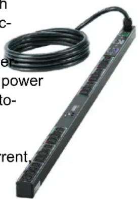
SmartZone™ Network-Enabled PDUs are available in a wide range of configurations and power connections and outlets and can be mounted vertically or horizontally.
Contacting Panduit
For Technical Support on PDU hardware and associated software, please contact Panduit Technical Support using one of the following methods:
1-866-721-5302 (toll-free)
Monday-Friday, 7:30 am - 5:00 pm CST
systemsupport@panduit.com
Symbols Used
| Symbol | Description |
 | Danger – Electric Shock Hazard |
 | Warning – Possible Safety Hazard |
 | Primary Earth Ground |
 | Secondary Earth Ground |
| | | ON |
| O OFF |
Equipment Overview
The power inlet/cord(s) connects the PDU to the electrical power source. On metered PDUs, the LCD displays the current load for each input feed or electrical phase per input feed.
• One shielded RJ45 connector for Ethernet connection
- Two unshielded RJ45 connectors for SmartZone™ sensors (For a list of supported sensors, see "Optional Accessories".)
For IEC C-20 inlet PDUs, a customer-supplied cord is used for connection to the power source. The connection end to the PDU has an IEC C-19 plug for connection to the PDU. The opposite end of the cord shall have a plug suitable for connecting to the customer supplied receptacle. The cord and plug shall be rated for 20A in North America and 16A outside of North America. The connection to the PDU should be made prior to connecting to the power source
Model Numbering Format
This section describes the model numbering format used to identify equipment in the PDU series.
PDU devices are numbering using one of the following formats:
• P1N-ABCDEFGHJKLM
• Q1N-ABCDEFGHJKLM
The P1N prefix indicates that the model is intended for horizontal mounting. The Q1N prefix indicates that the model is intended for vertical mounting.
The remaining series of letters represent values as defined in the table below.
| Letter What It Represents | |
| A | any numeral, 1-8, indicating the phase wiring for the output circuit breakers and receptacles |
| B Any | letter, A-F, indicating input cord configuration |
| CD* | Any numeral, 1-5, and any letter, A-Z, indicating input plug type and rated voltage |
| E Any | numeral, 1-7, indicating the number of output circuit breakers |
| F | Any letter, A-Z, indicating the type of overload protection provided for the outlets |
| GH | Any two numerals, 01-45, indicating the number of output receptacles provided |
| JK | The letter ‘A’ or ‘B’ followed by any letter, A-Z, indicating the type and quantity of output receptacles provided |
| L | Any numeral, 0-9, or any letter, A-Z, indicating the length of the supply cord |
| M Any | numeral, 0-9, indicating the color of the enclosure |
* Voltage and amperage ratings:
120V, single-phase, 10A, 12A, 15A, 16A, 20A, 24A or 30A
208V, single-phase, 10A, 12A, 13A, 15A, 16A, 20A, 24A, 30A, 48A or 60A
230V, single-phase, 16A, 32A, or 48A
208V, three-phase (delta), 16A, 20A, 24A, 30A, 40A, 48A, 50A or 60A, 3W + PE
208V, three-phase (wye), 16A, 20A, 24A, 30A, 48A or 60A, 3W + N + PE
400V, three-phase (wye), 16A, 20A, 24A, 30A, 32A, 48A or 60A, 3W + N + PE
Model Numbers
This document contains the specifications for the following model numbers.
| Part Number |
| P1N1B1C0A10AKA0 |
| P1N1B1L2N08ATA0 |
| P1N1B1M2M10AKA0 |
| Q1N1A3W0A24AF00 |
| Q1N1B1C0A24AKA0 |
| Q1N1B1D0A24AKA0 |
| Q1N1B1E0A30AHA0 |
| Q1N1B1F0A30AHA0 |
| Q1N1B3H0A24AFA0 |
| Q1N1B3H0A30AHA0 |
| Q1N1B3H0A30AXA0 |
| Q1N2B1J0A30AHA0 |
| Q1N2B1L2N30AHA0 |
| Q1N2B1M2M24AKA0 |
| Q1N2B1N3N30AHA0 |
| Q1N2B1P3N30AHA0 |
| Q1N2B2C3N30AHA0 |
| Q1N2B2P6M30AHA0 |
| Q1N2B2Q0A30AHA0 |
| Q1N2B2T6N30AHA0 |
| Q1N2B2W6N30AHA0 |
| Q1N2B2W6N30APA0 |
| Q1N2B3J2M30AHA0 |
| Q1N2B4E3N30AEA0 |
Pre-Installation
The Rack PDU products covered by this guide are designed to be installed within EIA racks and cabinets. Use of this product in other applications is acceptable, but other precautions may be required to allow for specific installations not covered by this guideline.
Product Inspection
Inspect the product prior to installation. If the product has any visible signs of damage, please contact the supplier.
Installation
Before You Begin
Before installing your PDU, refer to the following lists to ensure that you have all the items shipped with the unit as well as all other items required for proper installation.
Standard Accessories
Mounting Hardware:
• Vertical models:
Affixed button mounts
- Horizontal models:
Appropriate local mounting brackets and screws
Cables/Adapters:
- RJ45 patch cord cable
Hardwire PDU installation instructions
This product is intended to be hardwired by the customer must be installed by a qualified electrician AND adhere to all national & local electrical codes.
- To install, remove the (4) securing screws on the removable user panel.
- Unscrew strain relief grommet cap (indicated below) and feed the power cable through the grommet cap & the input gland.
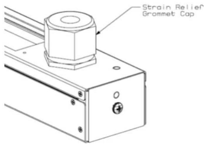
-
Ensure conductors are stripped adequately, exposing 15mm of copper.
-
Conductors shall be connected in-line with the terminal markings provided as shown below (Line 1 = X; Line 2 = Y; Line 3 - Z). Ensure screws are secure for each conductor by applying a torque of 2.3 N-m (20 in-lb.).
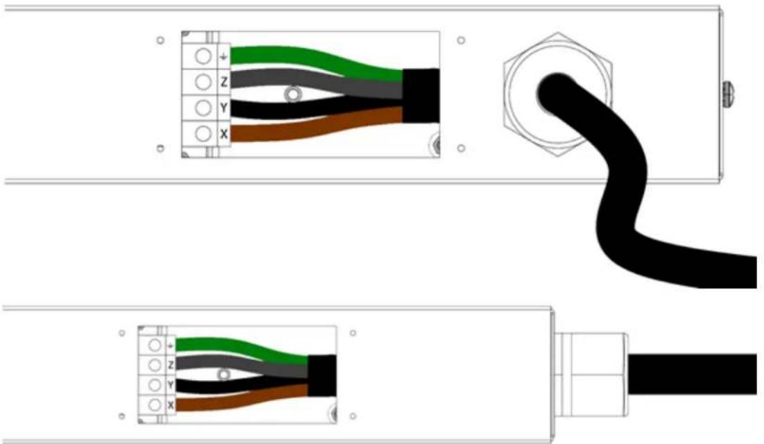
natural_image
Diagram showing three cable connector assemblies with color-coded wires and connectors (no text or symbols)-
Ensure conductors have enough slack (none should be under tension).
-
Feed grommet cap down cord and secure to input gland. Reference the table below to ensure the grommet cap is torqued correctly.
| Gland Size Grommet Cap | |
| M16 1.5 | N-m (13 in-lb.) |
| M20 3.0 | N-m (27 in-lb.) |
| M25 | 4.0 N-m (35 in-lb.) |
| M32 | |
| M40 15 | N-m (132 in-lb.) |
| M50 20 | N-m (177 in-lb.) |
| M63 30 | N-m (266 in-lb.) |
- Re-install removable cover plate with the screws removed in step 1.
- Connect the other end of the power cord to a suitably rated disconnect device.
- Switch utility circuit breaker "On".
Unterminated Cord PDU installation instructions
This product is intended to be hardwired by the customer must be installed by a qualified electrician AND adhere to all national & local electrical codes.
To install, match the corresponding conductor color to the matching phase in your facility. Reference the color guide below:
| Conductor Insulation Color Line Number | |
| Brown Line1 / X | |
| Black Line 2 / Y | |
| Grey Line 3 / Z | |
| Blue Neutral | |
| Green (may include Yellow stripe) Ground | |
Optional Accessories
SmartZone Environmental Sensors:
- Smoke Sensor
- Humidity Sensor
• Water Rope Sensor - Door Sensor
• Temperature Sensor
• Water Contact Sensor - Air Flow Sensor
• Passive Infra-Red Motion Detector
Additional Required Items
- Flathead and Phillips screwdrivers
- Appropriate local AC power receptacle to power the PDU
- Local active Ethernet port to communicate with the PDU
Safety Precautions
This section contains important safety and regulatory information that should be reviewed before installing and using the Rack PDU.
Servicing
There are no user-serviceable parts inside these products. Any maintenance or repair must be performed by approved service-trained personnel. Opening the unit will void the product warranty.
Product Safety Warnings

Warning: Use only in dry locations. Indoor use only.
PDU hardware has an International Protection Rating of IPX0.
The installer must connect the power distribution unit to an electrical supply that has a protective Earth conductor.
For pluggable equipment, the socket outlet should be installed near the equipment and should be easily accessible.

Warning: For permanently connected equipment, a readily accessible disconnect device should be incorporated external to the equipment.
Power distribution products must be protected by a branch circuit protective device rated at the maximum rating of the product specified on the product rating label.
To avoid risk of overload, do not plug additional multiple outlet power distribution devices into the power distribution unit socket outlets.
This equipment is intended only for installation and use in a Service Access Location in accordance with the following installation and use instructions.
This equipment is designed to be installed on a dedicated circuit.
• The dedicated circuit must have circuit-breaker or fuse protection.
- Rack PDUs have been designed without a master circuit breaker or fuse to avoid becoming a single point of failure. It is the customer's responsibility to provide adequate protection for the dedicated power circuit. Protection of capacity equal to the current rating of the Rack PDU must be provided and must meet all applicable codes and regulations. In North America, protection must have a 10,000A interrupt capacity.

Warning: Always disconnect the power supply cord before opening to avoid elec-shock.

DANGER: High leakage current! Earth connection is essential before connecting /!

DANGER: Double Pole/Neutral Fusing: The plug on the power supply cord must stalled near the equipment and must be easily accessible.
Rules
These limits are designed to provide reasonable protection against harmful interference when the equipment is operated in a commercial environment. This equipment generates, uses, and can radiate radio frequency energy and, if not installed and used in
accordance with the instruction manual, may cause harmful interference to radio communications. Operation of this equipment in a residential area is likely to cause harmful interference in which case the user will be required to correct the interference at his own expense.
Changes/modifications not approved by the responsible party could void the user's authority to operate the equipment.
Environmental Specifications
- Operating Temperature: 0C to 40C
- Transportation Temperature: -10C to 70C
- Operating Humidity: 15% to 85% non-condensing
- Transportation Humidity: 5% to 90% non-condensing
Bonding
This product contains an external earthing screw with a star washer, which should be used for supplementary Earth bonding to the rack metalwork.
| Bonding | |
| Minimum Requirements for Bonding Conductors | |
| Up to and including 32A 12 AWG | |
| Up to and including 63A 8 AWG | |
| Up to and including 80A 6 AWG | |
| Screw Size | |
| Over 16A, less than or equal to 40A 5mm | |
| Over 40A, less than or equal to 63A 6mm | |
| 64A 7mm | |
Mounting
There are two mounting options for Rack RDUs
• Vertical Mounting
• Horizontal Mounting
Instructions for each mounting option are detailed below.
Vertical Mounting
The product is intended to be installed using the tool-less mounting buttons. These buttons locate in the fixing holes provided as shown in the following figure.
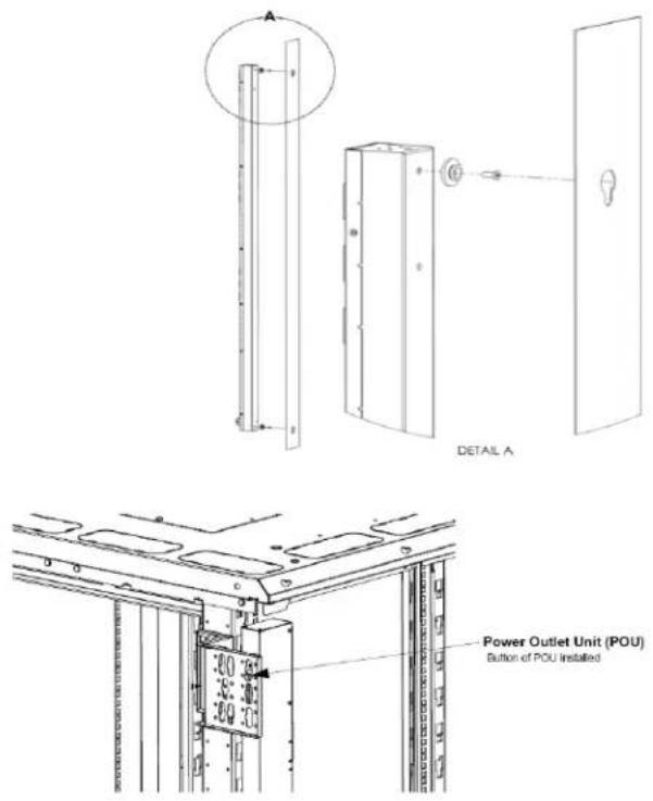
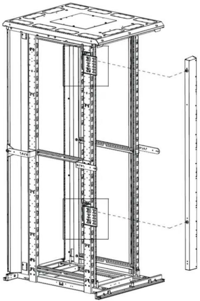
PDU Bracket for 4-Post Racks
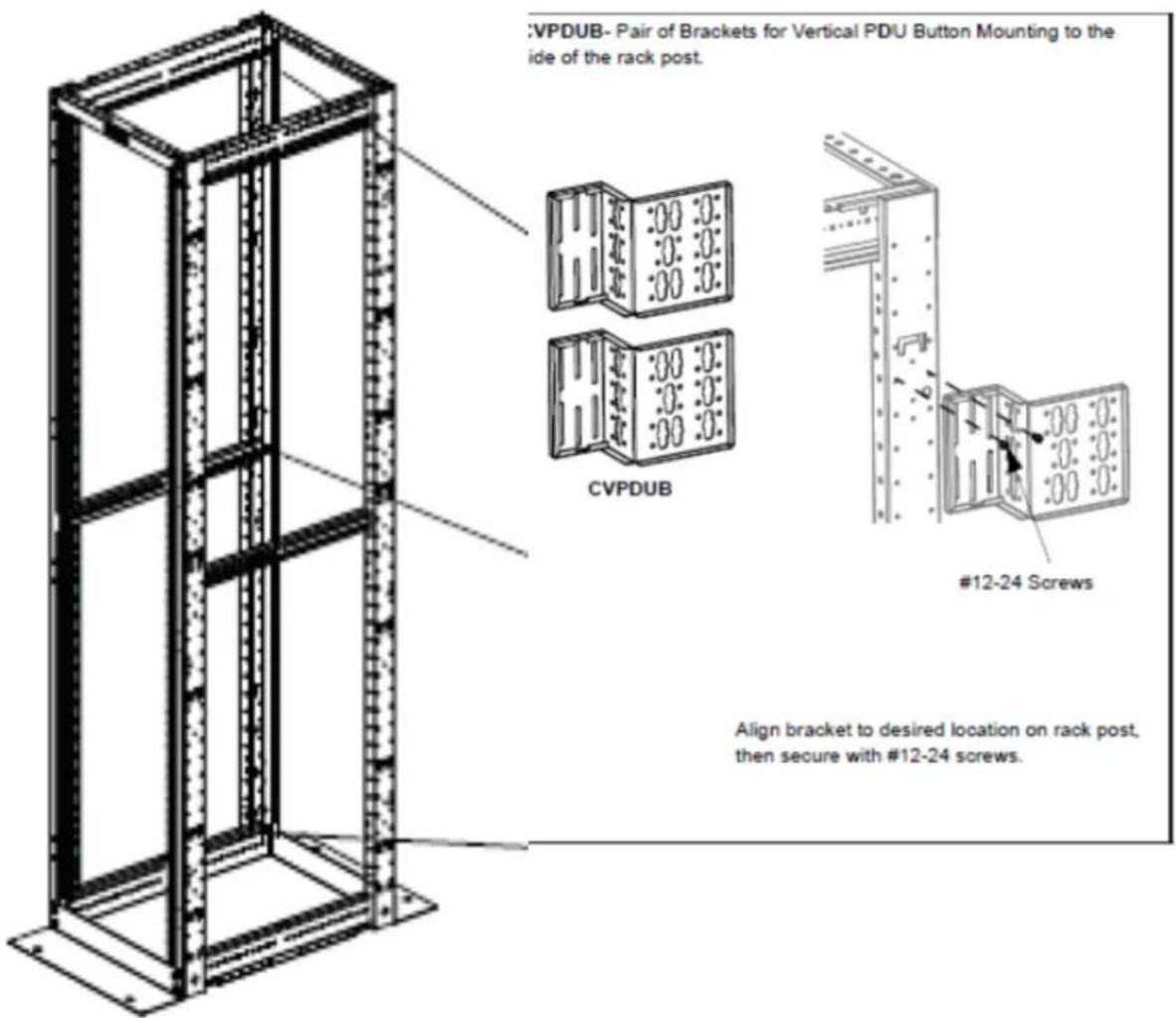
PDU Bracket for 2-Post Racks
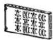
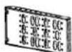
R2PPDUB
The R2PPDUB part contains the following components referred to in this instruction sheet:
• (2) Outer Mounting Brackets
• (2) Inner Mounting Brackets
• (12) #12-24 X 1/2" Screws
Installation Instructions-Outer Mounting Brackets
Attach (2) #12-24 X 1/2" screws to rack (per bracket) at appropriate locations.
Fasten outer mounting brackets to rack using the screws. The large flat surface with slotted holes may face outside or inside.
For mounting long (66.25") POU's, the brackets may be spaced vertically between 35 and 39 RUs apart, in 1 RU increments, measured from bracket base to bracket base.
For mounting short (39") POU's, the brackets may be spaced vertically between 19 and 23 RUs apart, in 1 RU increments, measured from bracket base to bracket base.
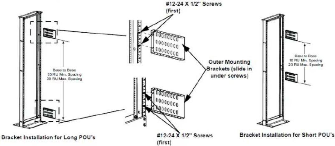
Installation Instructions-Inner Mounting Brackets
Slide inner mounting brackets into outer mounting brackets with the POU mounting keyway surface facing opposite the outer bracket slotted hole surface. Fasten brackets together using (4) #12-24 X 1/2" screws for each bracket set. (2) screws will be fastened on the top flange and (2) screws will be fastened on the bottom flange.
Important: (2) screws must be fastened in the most outward hole on each outer mounting bracket (1 top, 1 bottom). (2) screws must be fastened in the position where the hole in the inner mounting bracket is closest to the face of the rack, regardless of extended position.
Note: Multiple holes on the top and bottom of the brackets allow the distance from the rack a POU can be mounted to be adjustable. This means that the side facing POU can be mounted ranging from 3.7"-18.7" horizontally from the face of the rack. The rear facing POU can be mounted ranging from 12.3"-20.3" horizontally from the face of the rack.
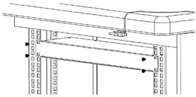
Horizontal Mounting
This product is intended to be installed using the rack's RU mountings via the brackets found at either end of the PDU with the accessory screws provided listed below.
• Horizontal Models
North American units
(4) #10-32 x 1/2" MOUNTING SCREWS
(4) #12-24 x 1/2" MOUNTING SCREWS
Global units
(4) M6 x 20mm MOUNTING SCREWS
(4) #12-24 x 1/2" MOUNTING SCREWS
natural_image
Technical line drawing of a mechanical assembly with railings and a support bracket (no text or symbols)Hardware
LCD Display
The display shows the firmware version number, device model number, serial number, MAC Address, IP Address, and electrical readings. The display automatically scrolls through the readings. Readings that can be displayed include:
- Start Up messages
- Configuration/serial/product number messages
- Error/Status messages
- Aggregate data
- Single phase data, 3 Phase Delta data, or 3 Phase Wye data
- Branch current data, if the unit has breakers
During normal operation, the mode button may be used to quickly advance through the LCD display pages.
Reset Button
Push the Reset button using a non-metallic item, similar in size to a paper clip, to reset the PDU device.
! Warning: a metallic item, such as a paper clip, is not recommended as a reset tool.
The reset tool should be inserted perpendicular to the surface of the device and pressed until the button is reached and is actuated.
The reset tool should bump into the button within 1/8 of an inch of being inserted, and should be lightly depressed and held for at least 1 second. The reset tool should never be inserted more than 1/4 of an inch.
Resetting the PDU device starts the bootloader. Wait between 1 and 30 seconds for the Display Backlight to blink on and off at a rate of 2 blinks per second. The bootloader stays in this mode for at least 4 seconds (8 blinks) if no user operation is detected.
Mode Button Operation
Bootloader Startup
When the user presses and holds the Mode button, the Display Backlight switches to one blink per second, indicating the bootloader is waiting for one of the following operations.
- If the user releases the Mode button after two blinks, the backlight goes solid-on and stays in the bootloader, entering the "firmware recovery mode". See the "Firmware Recovery Mode" section (below) for more details.
- If the user releases the Mode button after four blinks, the backlight goes solid-on and attempts to boot the “backup firmware image”.
- If the user does not operate the Mode button as described above, the Display Backlight is turned off. The “firmware updatable application image” continues loading.
Firmware Recovery Mode
The Network-Enabled PDU provides a firmware recovery mode in case a firmware update is interrupted while in progress and fails to complete successfully.
Note: Do not power cycle or restart a device while a firmware update is in progress.
If a firmware update does not complete successfully, and the device fails to be operational after 30 minutes, contact Panduit Technical Support.
1-866-721-5302 (toll-free)
Monday-Friday, 7:30 am - 5:00 pm CST
systemsupport@panduit.com
Application Startup
When the application is ready, a message is displayed on the LCD:
Starting up...
The display backlight blinks quickly three times and remains lit.
The LCD then displays:
Hold MODE button to reset to defaults...
The application stays in this mode for at least 5 seconds. If no button operation is detected, the application continues to normal system operation.
If the customer presses and holds the Mode button for 5 seconds, the following message displays on the LCD:
Hold MODE button more than 5 seconds to reset to defaults
If the customer continues to press and hold the Mode button, the following message displays on the LCD:
Reset to defaults is detected. Please release MODE button.
The customer should release the Mode button at this point. The following message displays on the LCD:
Device is Resetting to factory defaults.
If the customer does not operate the Mode button as described above, the application continues normal system operation.
Internal Error Notification
After system start up is complete, during normal operation of the unit, the LCD screen may blink. This typically indicates a temporary or persistent internal error condition.
If the condition is persistent, the LCD screen displays the word "STATUS:" followed by a hexadecimal code, similar to the following.
STATUS: 0x009000080
The hexadecimal code is a composition of per-outlet control, per-outlet monitoring and per-phase monitoring status. For example, if a three phase Per-outlet Monitoring or Switched unit loses a power phase, the status screen will reflect that communication to those boards has been lost.
For definitions and recommended actions on status codes, provide the displayed hexadecimal number to Panduit Technical Support.
Graphical User Interface
The Panduit Network Enabled Rack PDU provides access to configuration, power, and sensor data through a Graphical User Interface (GUI), using a standard browser. There are several ways to connect to the device's GUI, depending on your network configuration and the firmware revision of the device.
If the PDU has firmware revision 2.3.03 (or earlier), Static IP is the default. The configuration settings in this case are:
IPv4 Address:192.168.0.253
IPv4 Network:255.255.255.0
IPv4 Gateway:192.168.0.1
If the device has firmware revision 2.3.04 (or later), DHCP is the default, and one of the following scenarios will be used.
- If you have a DHCP Server available, connect to the appliance through that server, using the PDU's IP Address.
Note: The IP address for the Rack PDU is displayed on the device's LCD screen after the label IPv4
- If you do not have a DHCP server, you can run one on your PC. To connect to the device, use the IP address displayed on the LCD screen.
- If you want to use automatic IPv4 address configuration, you must activate DHCP on your PC and then connect directly to the PDU. This will give you an address on the 169.254.0.0/16 network. You can then connect directly using the IP Address displayed on the LCD screen.
Access the PDU Graphical User Interface
To access the GUI, open a web browser and enter the IP Address of the PDU. When the login page opens, you will be prompted to enter a Login and Password.
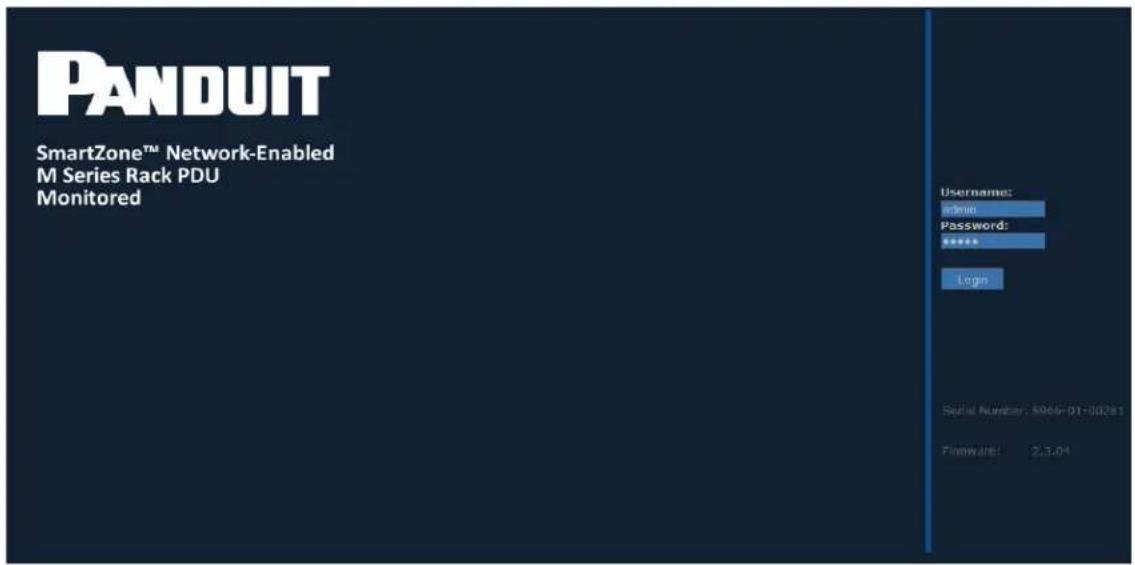
The default login and password are:
Login:admin
Password:admin
After successful login, the GUI opens to the Overview page.
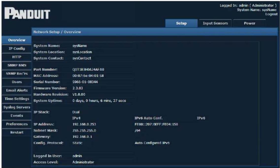
There are three modules within the GUI, each providing access to a different area within the PDU. The modules are:
- Set Up
- Input Sensors
- Power
To select a module, click the appropriate label along the top of the display.

The menu items that appear on the left hand side of the screen will change depending on the module selected.
Setup
When the setup module is selected, the following menu items appear along the left hand side of the display.
| Setup Menu Options | |
| IP Config View | or edit the network settings |
| HTTP View or | edit the HTTP settings |
| SNMP NMS View | or edit information about NMS access |
| SNMP Rec’rs View | or edit information about the SNMP Receivers |
| Users View or | edit information about all users |
| Email Alerts View | or edit email alert settings |
| Time Settings View | or edit information about the date and time |
| Syslog Servers View | or edit information about the Syslog servers |
| Events View Event history | |
| Preferences View | or edit system preferences |
| Restart Provides | the ability to restart the PDU |
Detailed information on each of these menu items can be found in the corresponding sections below.
IP Config
Selecting this option displays the IP Configuration page, where network settings for the unit can be set. This is the information that will be displayed on the Overview page.
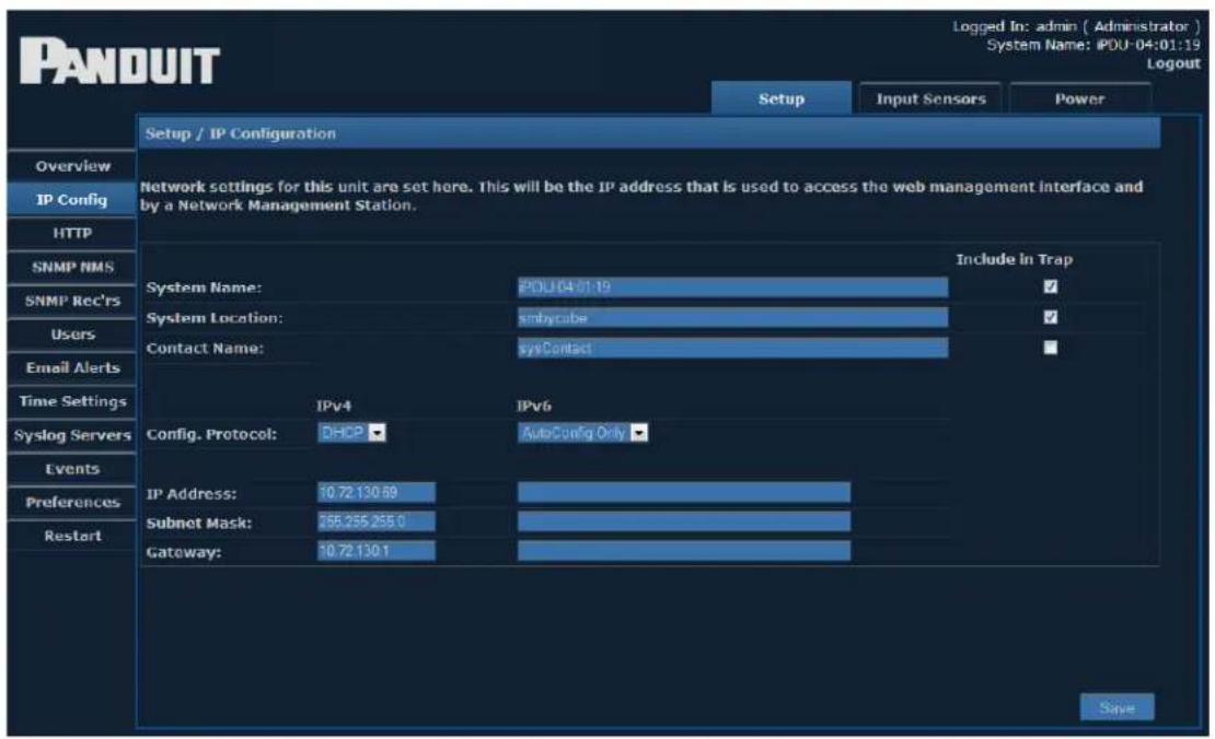
| IP Configuration | |
| System Name The | name of the PDU |
| System Location The | location of the PDU |
| Contact Name A person to contact regarding the PDU | |
| Config Protocol Select the configuration protocol | |
| IP Address The IP address of the PDU | |
| Subnet Mask The Subnet Mask for the PDU IP Address | |
| Gateway The Gateway for the PDU IP Address | |
IPv4 Address Configuration
There are several kinds of IPv4 address configurations that you can choose from. Static IPv4 is the default configuration for firmware releases before firmware version 2.3.04. DHCP is the default configuration for firmware releases after firmware releases 2.3.03.
The DHCP configuration (Dynamic Addressing provided by Infrastructure)
- The DHCPv4 client allows the user to obtain IPv4 configuration information from a DHCPv4 server. The functions that the DHCPv4 client performs include:
- Basic server discovery and address assignment.
- Address renewal and rebinding.
- Address depreciation when the preferred lifetime expires.
- Address removal when the valid lifetime expires.
- Address release when the interface is closed.
Static Configuration (Manual Addressing)
- The customer must specify an IP address, Subnet mask, and Gateway.
IPv6 Address Configuration
There are several kinds of IPv6 address configuration that can be chosen.
AutoConfig only (link local addressing)
- IPv6 AutoConfig addressing is always available.
- The customer does not specify an IP Address, IPv6 prefix (shown as Subnet Mask in the web UI) or Gateway.
- The link local address is always based on the MAC Address converted into an EUI-64 address.
For example, the MAC Address: 00:07:6E:04:01:28 is always always accessible at the IPv6 Link local address: FE80::0207:6EFF:FE04:0128.
Note that the first byte of the MAC address has 0x02 added to it where FF:FE is inserted into the middle of the MAC address bytes. The technical term for this address format is stateless address autoconfiguration (SLAAC) using the modified EUI-64 format.
Static configuration (manual addressing)
- The customer must specify an IP Address, IPv6 prefix (shown as Subnet Mask in the web UI) and Gateway.
- Static IPv6 configuration works concurrently with stateless address auto-configuration.
DHCPv6 configuration (dynamic addressing provided by infrastructure)
The DHCPv6 client allows the user to obtain IPv6 configuration information from a DHCPv6 server and works concurrently with stateless address autoconfiguration. The functions performed by the DHCPv6 client include:
- Basic server discovery and address assignment
- Address renewal and rebinding
- Address depreciation when the preferred lifetime expires
- Address removal when the valid lifetime expires
- Address release when the interface is closed
The current implementation of the DHCPv6 client has certain limitations. The following are the features that are currently not supported:
- Authentication
• RECONFIGURE Messages
• IA_TAs (Temporary Addresses) - Rapid Commit FQDN (Fully Qualified Domain Name)
- DUID-LLT
- IA_PD (Identify Association for Prefix Delegation)
Accessing the appliance via a web browser using IPv6
A web browser can access IPv6 addressed devices using the full or short form IPv6 address.
For example, to access an appliance with the MAC address 00:07:6E:04:01:28, you could navigate to the AutoConfig address: http://[FE80::0207:6EFF:FE04:0128]/ or https://[FE80::0207:6EFF:FE04:0128]/. The open and close square brackets indicate an IPv6 address.
When using a PC with more than one IPv6 enabled network interface (multi-homing), IPv6 scoped URLs may be necessary to access a device. Not all web browsers fully support IPv6 scoped URLs. Therefore, this problem must be worked around by enabling IPv6 on only one interface at a time on the computer running a web browser to access the appliance.
HTTP
This page allows you to choose the access method for the web management interface.
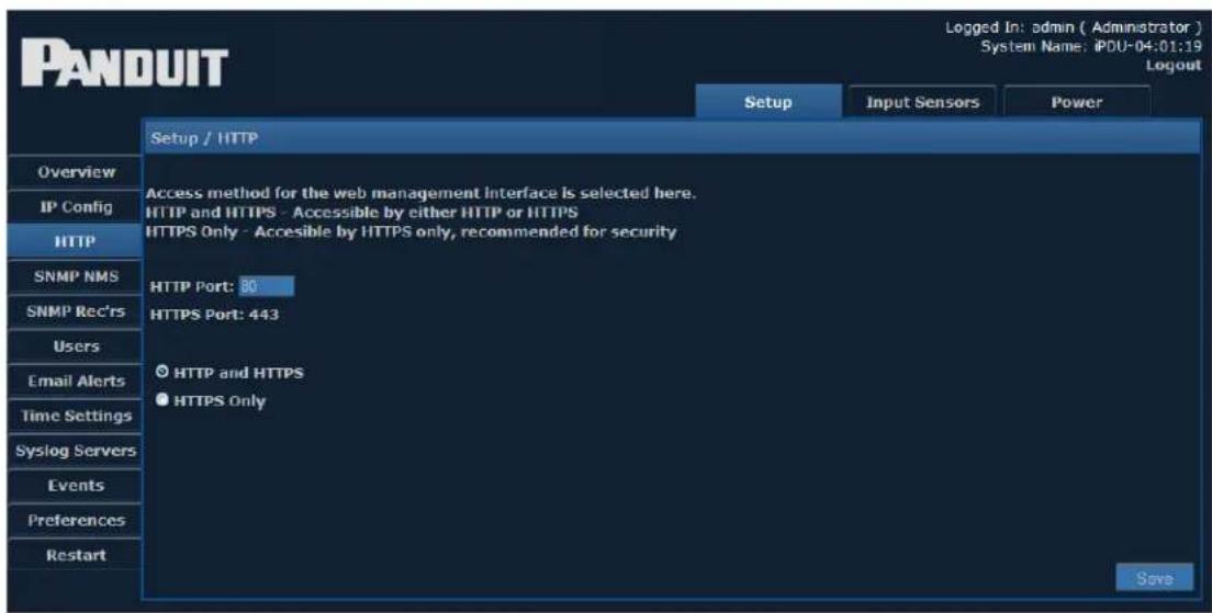
To choose the access method, click the corresponding radio button and enter the appropriate Port number. Typically the Port does not need to be changed from its default setting (80 for HTTP or 443 for HTTPS).
HTTP or HTTPS access methods can be used. However, HTTPS is recommended for security.
When you save any changes to this page, you will see the following message:
After Saving, would you like to restart the unit?
Click 'OK' to restart, otherwise 'Cancel'.
If you select Cancel, you are reminded that you will need to manually restart for any changes to take effect.
SNMP NMS
This page provides access for Network Management Stations.
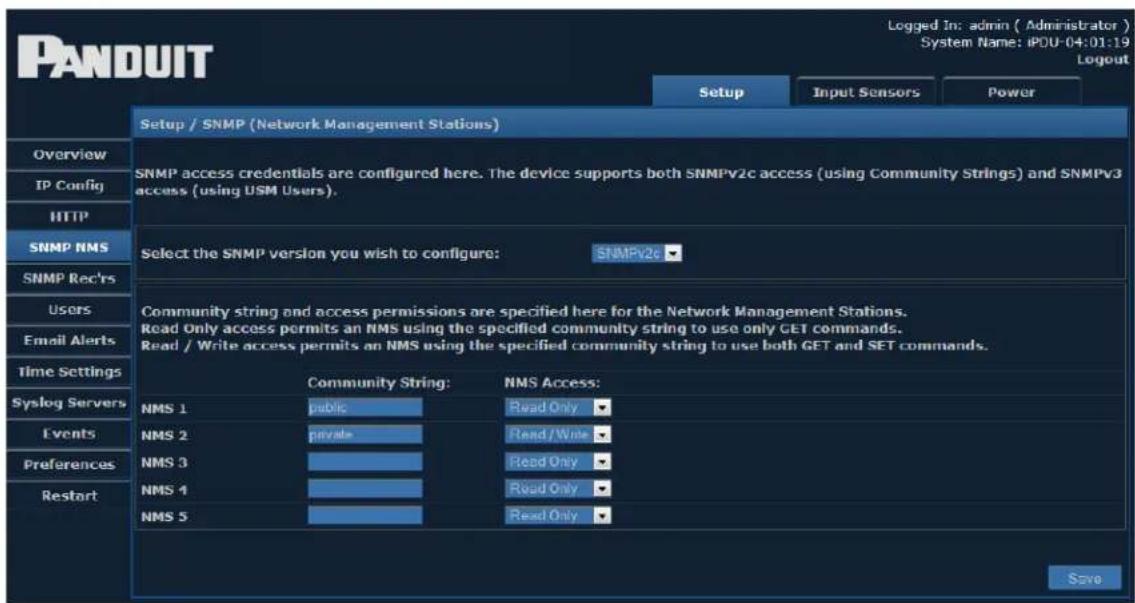
Both SNMPv2c and SNMPv3 protocols are supported simultaneously. You must enter the credential information for any device that needs to communicate with the unit via Simple Network Management Protocol (SNMP).
Select the SNMP version settings you wish to edit from the drop-down menu.
For ease of initial deployment and discovery, default credentials for both versions have been provided:
- The SNMPv2 default Community Strings are "public" (read-only access) and "private" (read/write access).
- The unit will respond to SNMPv3 requests using the MD5 authentication and DES privacy protocols. To use the "authUser" and "secureUser" user names, an Authentication and/or Privacy password must first be set.
- To disable a specific version of SNMP, simply remove the Community Strings (SNMPv2c) or User Names (SNMPv3) and save the configuration.
Enter the Community String for any device that must access the unit's SNMP functions.
Access permissions can be selected from the drop-down menu under NMS Access.
| Access Permission Settings | |
| Read Only Permits the NMS to use only GET commands | |
| Read / Write | Permits the NMS to use both GET and SET commands |
SNMP Receivers
The SNMP Receivers page displays information for all devices that receive SNMP traps sent from this unit.
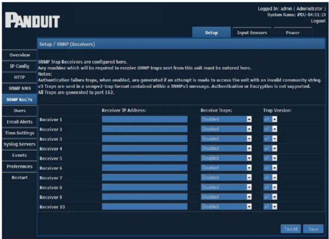
Enter the IP address and Community String for any device that will be required to receive SNMP traps. Usually any SNMP NMS entries should also be entered here. From the dropdown menu under Receive Traps, select one of the following:
| Receive Traps Settings | |
| Disabled Receiving traps is prohibited | |
| Enabled | Allows the specified NMS to receive the unit's standardrange of traps |
| Enabled (Incl. Auth Fails) | Receive traps – causes the unit to issue traps if the an unauthorized attempt to access the unit's SNMP tions. |
The version of trap/notification can be selected from the dropdown menu under Trap Version.
SNMP Trap Description Text Format
SNMP Traps are detected when certain events are detected. The format of the generated text messages is explained below.
NOTE: Before the text message is sent, all leading, trailing and repeated whitespace is removed.
The SNMP trap text format is:
<snmp-trap-format> ::= <opt-timestamp-prefix> " " <opt-system-name> " " <opt-system-location> " " <opt-contact-name> " " <trap-kind> " " <source-name> " " <chan-no> " " <user-text> " " <value> " " <data-type> " " <opt-timestamp-postfix>
The following table contains definitions for each parameter.
| SNMP Trap Text Format | |
| Optional. When Setup -> IP Config / System Name / Include In Trap is checked, Setup -> IP Config -> System Name is displayed. | |
| Optional. When Setup -> IP Config / System location / Include In Trap is checked, Setup -> IP Config -> System Location is displayed. | |
| Optional. When Setup -> IP Config / Contact Name / Include In Trap is checked, Setup -> IP Config -> Contact Name is displayed. | |
| Optional date/time prefix. (When Setup / Preferences Timestamp Traps: is set to “Prefix”.) | |
| Type of notification. Warning, Critical, Information | |
| On, Information Off, Cleared, Unknown. | |
| ::= Data source. Example: “Input 01”. | |
| ::= "("") | When available, the number of the sensor Port the alert came from. |
| ::= | Event description of the reason for the trap. See the “User Text” strings on the Trap Configuration pages or the per-sensor configuration pages. Example: For contact sensors, the “Normal Trap User Text” or “Non-Normal Trap User Text” is used. |
| ::= | The value at which the event occurred. Example: “900” indicates 90% humidity. |
| ::= Type of the data. Example: “relative humidity” | |
| ::= | Optional date/time postfix. (When Setup / Preferences Timestamp Traps: is set to “Append”.) |
Users
Select the Users menu item to add or modify Web GUI User settings.
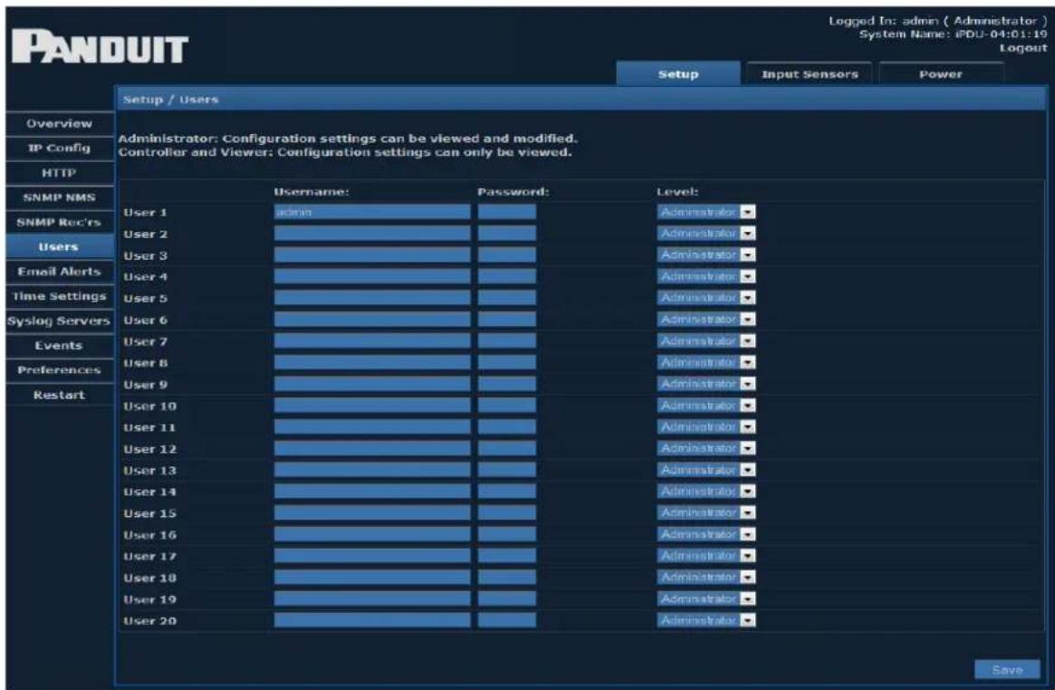
The PDU GUI comes with the Administrator login predefined as:
- Login:admin
- Password:admin
To add new users, enter a unique Username and Password for each, then select the desired level of permission. You may configure up to 20 users.
Level of permission for each user can be selected from the drop-down menu on the right. There are three different permission settings:
| User Permission Settings | |
| Administrator | Allows all configuration settings to be viewed and modified |
| Controller | Allows configuration settings to be viewed, but only obtain pages can be modified |
| Viewer Allows | configuration settings to be viewed only |
Email Alerts
On this page, you can edit email alert settings for traps. You may set up to 10 email receivers.
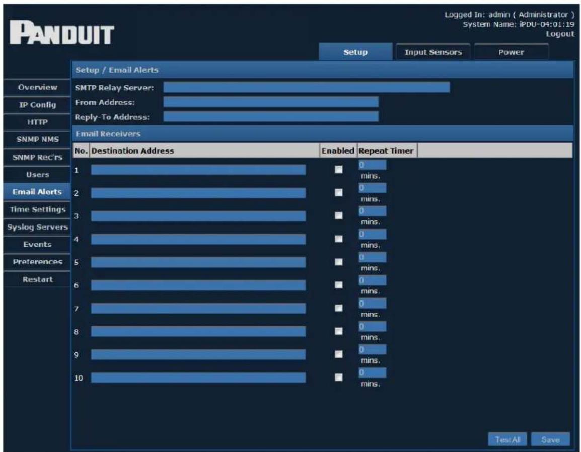
| Email Alerts | |
| SMTP Relay Server | The IP Address of the SMTP Server |
| From Address Address from which the alert emails are sent | |
| Reply-To Address | Address to which the email receivers can reply |
| Destination Address | Address that will receive the email alerts |
| Enabled | Toggle the check box to enable or disable alerts to each address. |
| Repeat Timer Number of minutes after which the email alert will repeat | |
Time Settings
The Time Settings page allows you to view or edit the current date and time.
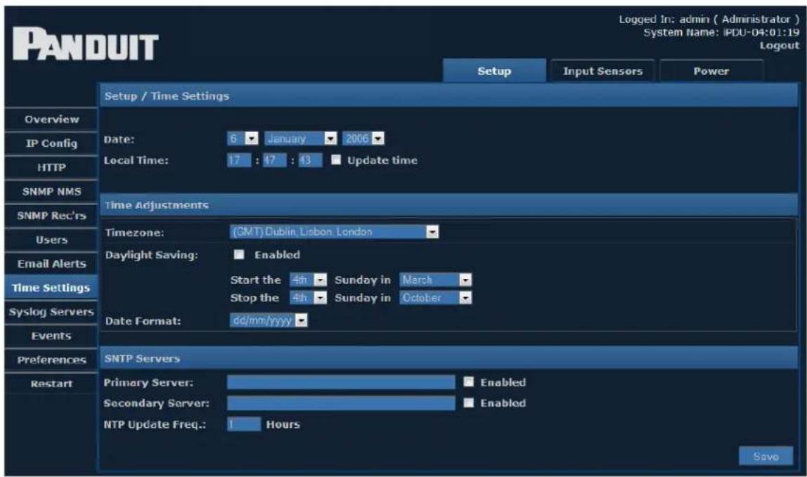
Select the correct day, month, and year from the dropdown menus, and verify the local time. If you want to change the time, you must check the Update time checkbox.
Time Adjustments
Select the correct time zone from the drop-down menu.
- Daylight Saving can be enabled or disabled by clicking the check box. If Daylight Saving is enabled, select start/stop dates from the subsequent drop-down menus.
- Date Format allows the administrator to choose whether the date is displayed with the day or month first. For example, the date August 20, 2013 can be displayed in one of two ways:
20/08/2013 (DD / MM / YYYY)
or
08/20/2013 (MM / DD / YYYY)
Select the desired format from the dropdown menu.
- SNTP Servers - Simple Network Time Protocol synchronizes the clocks of computer systems over a network. Enter the IP address of an SNTP server, and specify (in hours) how often the time should be updated.
Syslog Servers
This page allows you to view or edit information about the Syslog Servers currently being used.

From the Enabled drop-down menu, you can choose which syslog servers are enabled. Fill in the following fields for each Syslog server.
| Syslog Server Setup | |
| Display name The | name of the Syslog server |
| IP Address The | IP address of the Syslog server |
| Port The num | ber of the port being used |
| Log Event Types | Click the check boxes to choose which events to log. |
Events
The View Events page shows a history of events that have occurred, along with specific details about each event.
![PANDUIT Setup Input Sensors Power View / Events Overview IP Config HTTP SNMP NMS SNMP Rec'rs Users Email Alerts Time Settings Syslog Servers Events Preferences Restart View Events: 2000 ▼ January ▼ Latest First ● Earliest First [Show] Date / Time Type User Event Data Jan 06 17:47:40 User Login. User:admin Jan 06 17:45:43 Auto Logout. User:admin Jan 06 17:26:06 User Login. User:admin Jan 06 17:24:54 User Logout. User:admin Jan 06 17:24:45 User Login. User:admin Jan 06 17:10:37 User Logout. User:admin Jan 06 17:07:53 User Login. User:admin Jan 06 17:06:26 Auto Logout. User:admin Jan 06 16:59:38 User Login. User:admin Jan 01 00:00:12 Web Preferences Change. User:System Skin Id: 255 Jan 16 01:17:33 Application Image Updated. User:System Jan 16 00:33:52 User Login. User:admin Jan 15 22:37:31 Auto Logout. User:admin Jan 15 20:32:21 User Login. User:admin Jan 15 20:31:48 Auto Logout. User:admin Jan 15 20:26:30 User Login. User:admin Jan 15 20:06:03 Auto Logout. User:admin Jan 15 20:00:49 User Login. User:admin Jan 15 19:42:24 Auto Logout. User:admin Jan 15 19:37:18 User Login. User:admin](/content/2026/05/983494/images/50eb063f2b12bd32f041925cb276745a0f0bdb3798ebc4b18924d6f2667d4fbc.jpg)
To specify a range of events to view, select the desired year and month from the drop-down menus, then click Show.
Date/Time, Type, User, and Event Data for each event are displayed.
Events can be ordered Latest First or Earliest First by clicking the corresponding radio button.
Preferences
The Preferences page allows you to edit system preferences.
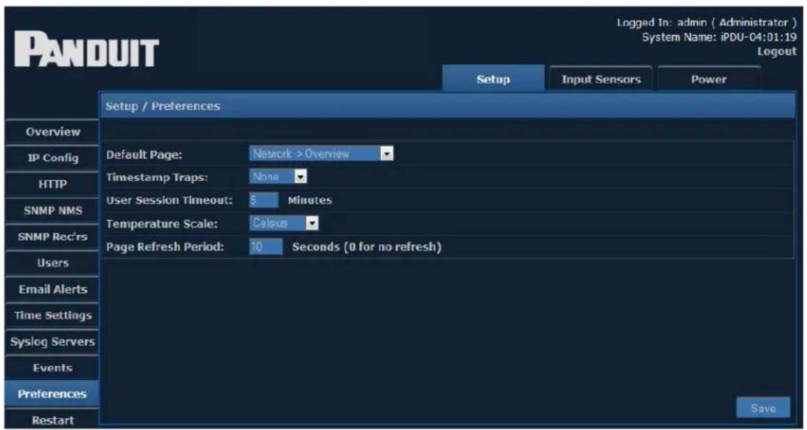
| Preferences | |
| Default Page | From the dropdown menu, select the first page you want to open when a user logs in. The preset default page is the Overview page. |
| Time stamp Traps | Choose from the dropdown menu where the timestamp will be found on traps. There are three options:Prefix – timestamp at the beginningAppend – timestamp at the endNone – no timestamp |
| User Session Timeout | Enter a number of minutes, after which a session will be timed out if the user is inactive. |
| Temperature Scale | Select Celsius, Fahrenheit, or Kelvin from the dropdown menu. |
| Page Refresh Period | Enter a number of seconds, after which the page will automatically refresh. If 0 is entered, the page will not refresh automatically. |
Restart
Clicking the Restart option brings up the following screen:
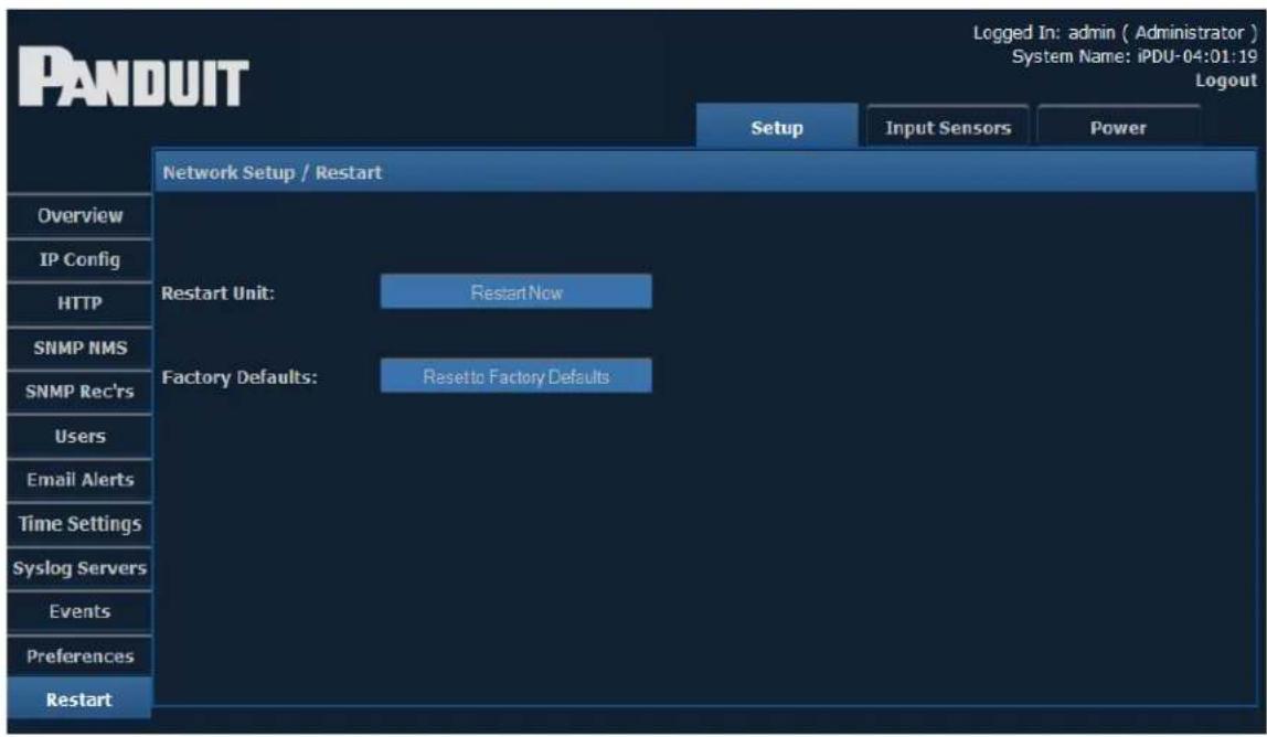
To restart the unit or restore to factory defaults, click the corresponding button.
Note: Resetting to factory defaults will restart the device.
Input Sensors
When the Input Sensors module is selected, the following items appear along the left-hand side of the display.
| Input Sensors Menu Options | |
| Status View information from connected input sensors | |
| Defaults View or edit default settings for input sensors | |
| Configure Configure sensor inputs | |
| Sensor Trap Text View or edit trap text |
Detailed information on each of these menu options can be found in the corresponding sections below.
Status
The Status page displays information from connected input sensors.
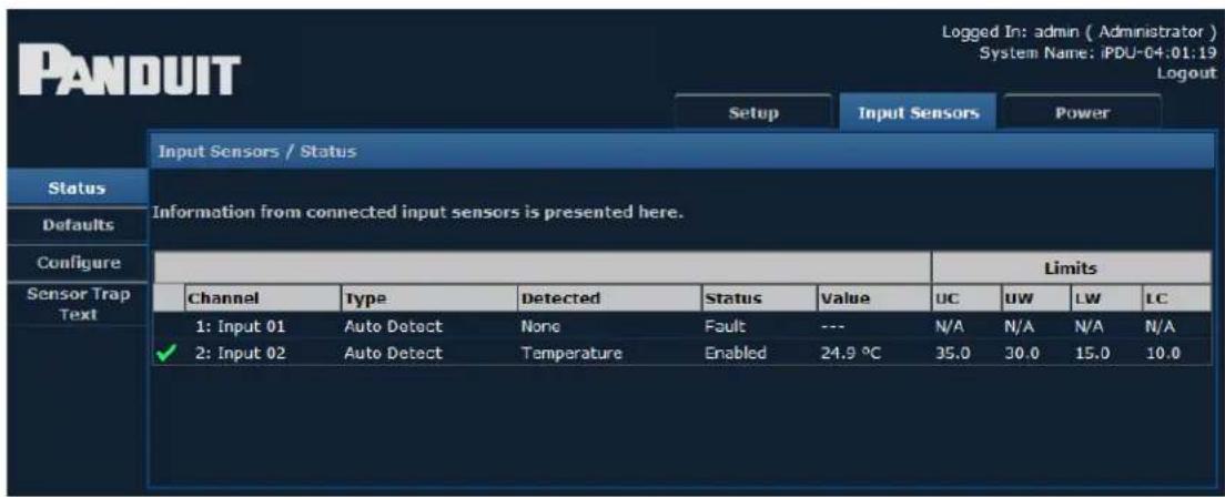
The following Status Indicators are displayed next to input channels to allow quick determination of normal, warning, and critical alarm statuses.
| Status Indicators | |
| √ | All thresholds within limits |
| × | Upper Control Limit reached/exceeded |
| ! | Upper Warning Limit reached/exceeded |
| ! | Lower Warning Limit reached/exceeded |
| × | Lower Control Limit reached/exceeded |
This page may also display the strings "O/R" and "U/R" in place of the input sensor measurement. This indicates an over-range or under-range condition.
• O/R - Value is Over Range
• U/R - Value is Under Range
Defaults
This page allows you to choose default settings for Temperature Sensors, Humidity Sensors, Analog Voltage, and Open/Close Contacts.
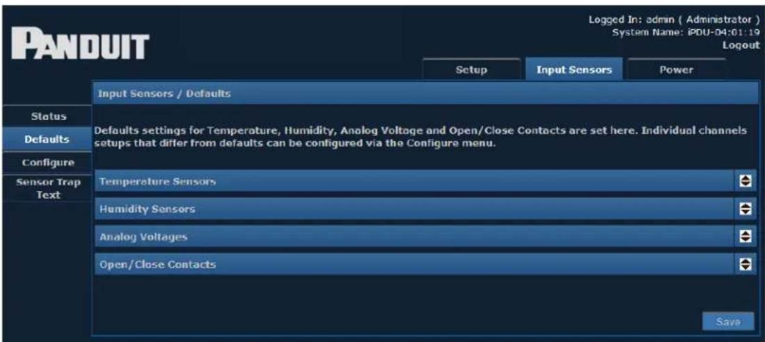
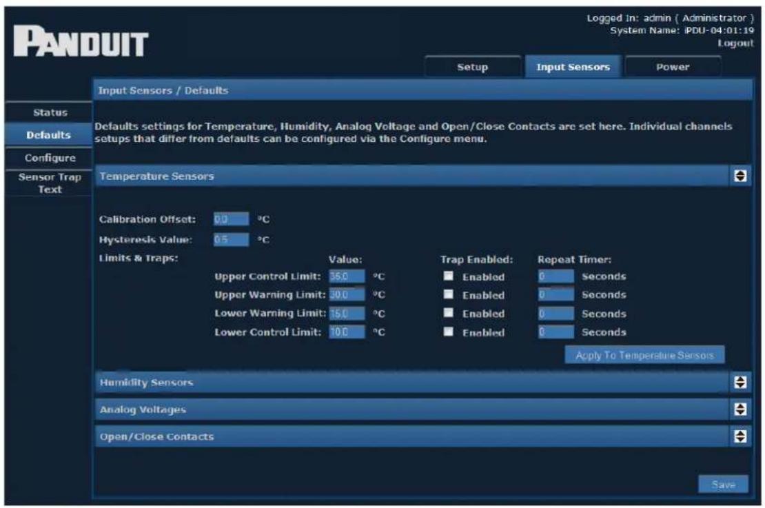
Clicking the arrow opens a drop-down for each Sensor type. For Temperature Sensors, the defaults will display similar to the following:
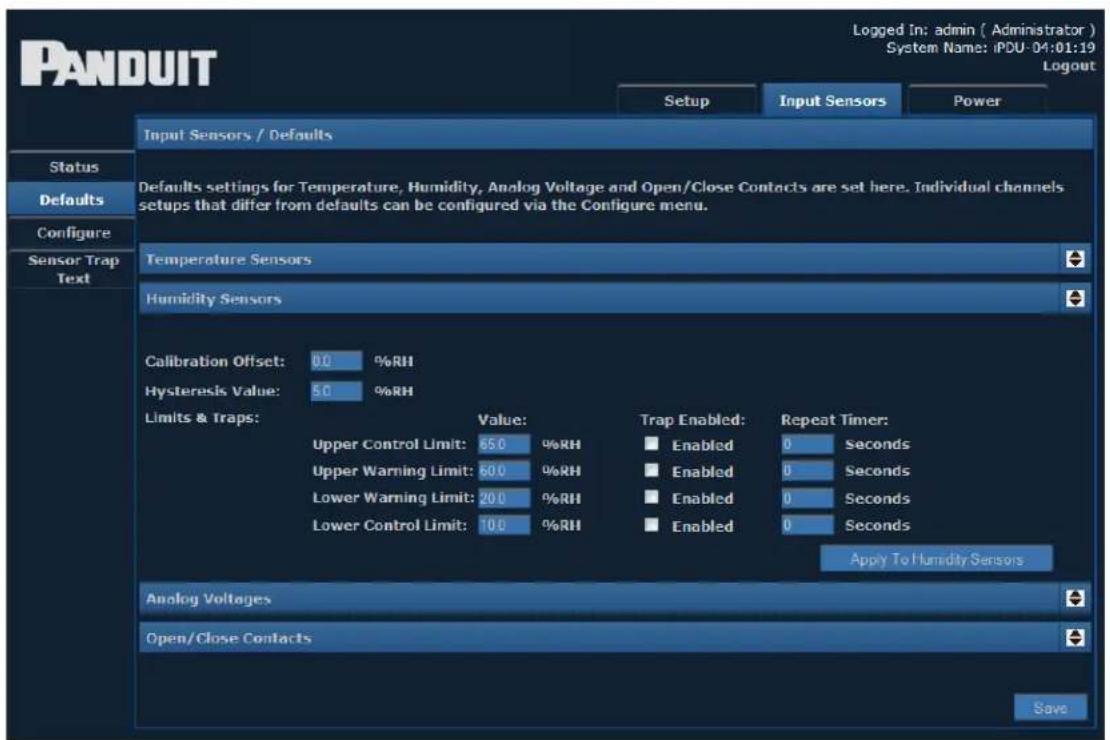
The Humidity Sensors screen displays default information as shown below.
The Analog Voltage screen displays default information as shown below.
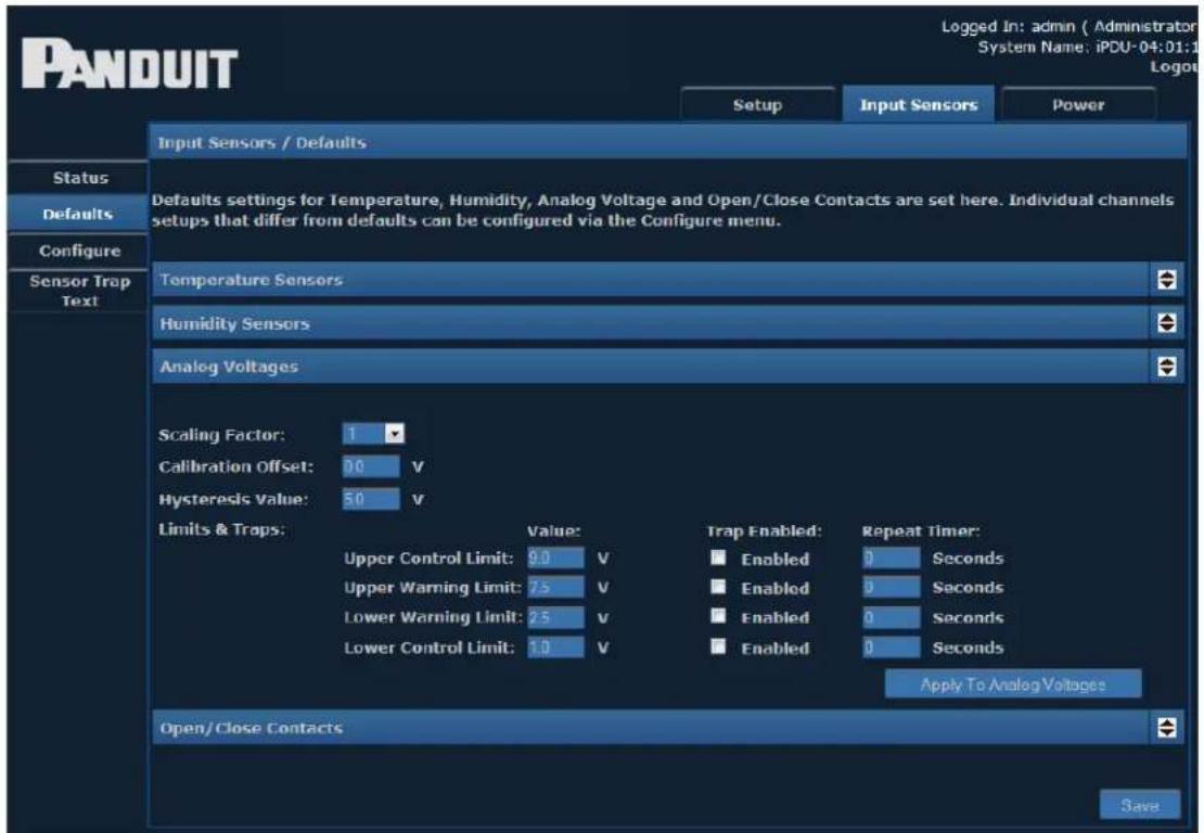
Explanations of the editable fields in the drop-down menus for Temperature, Humidity and Analog Voltage can be found in the table below.
| Defaults- Temperature, Humidity, and Analog Voltage | |
| Scaling Factor(Analog Voltage only) | The scaling factor is a value multiplied against the measured Analog Voltage to produce the Input Sensor measurement.Example: Given a measurement of 10 Volts on the input sensor and a Scaling Factor of 100, the web UI and SNMP interface will report a value of 10 × 100 = 1000 Volts as the sensor measured value.Note: The [Upper|Lower] [Control|Warning] Limit fields apply to the post-scaled value. |
| Calibration Offset | Alters the actual reading of a sensor by the amount specified.Example: If a Calibration offset of 6 was used and a sensor's true reading was 36, the indicated reading used for displayand alarm purposes would be 42. This works in an identical way for both temperature and humidity sensors. |
| Hysteresis Value | The hysteresis default value to be applied to sensors is. The value specified is an offset from a sensor's threshold values.Example: A hysteresis value of 5 would mean that in the case of an Upper Control Limits alarm, the alarm value would have to reduce to 5 below the threshold value before another alarm is issued. |
| Upper Control Limit | The value at which an Upper Control alarm will be issued. |
| Upper Warning Limit | The value at which an Upper Warning alarm will be issued. |
| Lower Warning Limit | The value at which a Lower Warning alarm will be issued. |
| Lower Control Limit | The value at which a Lower Control alarm will be issued. |
The Open/Close Contacts screen displays the following default information.
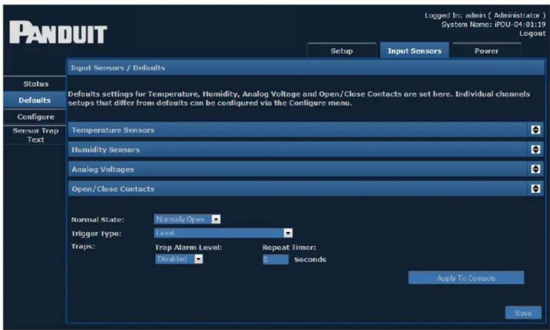
| Defaults- Open/Close Contacts | |
| Normal State | Normal state specifies the condition in which a contact is considered to be ‘Normal’, ‘Non-alarmed’ state. Devices such as smoke alarms and air conditioning units often have normally open contacts. In order to receive alarm indications from these types of units, setting normally open would cause alarms to be issued when the monitored contact closes. Setting normally closed, in the case of a rack cabinet door, would cause an alarm condition when the door was opened. |
| Trap Alarm Level | Rather than using [Upper|Lower] [Control|Warning] Limit settings, the Open/Close Contact sensors provide a Trap Alarm Level drop down menu with the following options:DisabledCriticalWarningInformationWhen the Trigger Type state occurs, if the Trap Alarm Level is not Disabled, a trap with the given Trap Alarm Level string content is generated. |
| Trigger Types | Trigger type defaults for Open/Close sensors are specified here. The three available options for trigger types are:LevelLevel triggering is the default mode. When an input physically transitions from a Normal to Non-Normal state an alarm will be triggered. However the alarm will only persist while the input remains in a Non-Normal state. When the input returns to a normal state the alarm will be cleared.Normal to Non-Normal (Positive Edge)This type of triggering may be used in situations where a momentary type input (e.g. shock sensor, PIR etc.), is used. Since these types of inputs are momentary any alarm condition which occurs, no matter how short, will persist until manually cleared. Positive Edge triggering is used whenan alarm is required to persist after an input changes from the Normal state to the Non-Normal state.Non-Normal to Normal (Negative Edge)This type of triggering may be used in situations where a momentary type input (e.g. shock sensor, PIR etc.), is used.Since these types of inputs are momentary any alarm condition which occurs, no matter how short, will persist until manually cleared. Negative Edge triggering is used when an alarm is required to persist after an input changes from the Non-Normal state to the Normal state. |
| Repeat Timer | Causes alarm traps to be reissued after a specified amount of time if the alarm condition is still present. Setting the timer to zero (0) disables repeat traps. |
The drop-down menus can be closed by clicking on the corresponding arrows again.
Configure
The Configure page, shown below, allows you to configure sensor inputs.
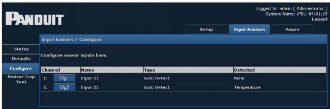
Clicking one of the configuration buttons – Cfg 1 or Cfg 2 – displays the following screen:
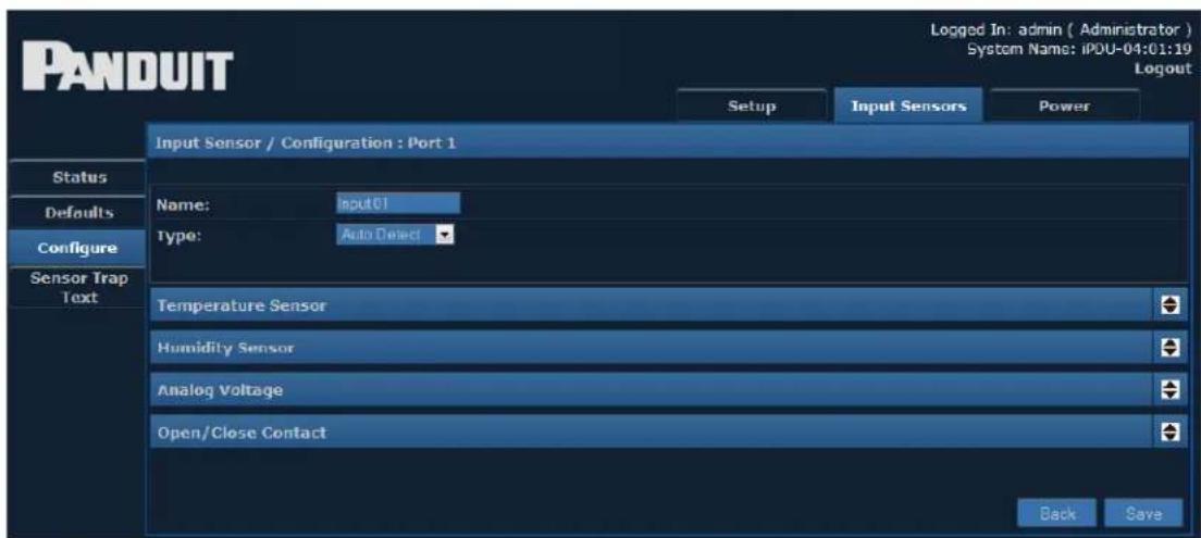
Individual settings can be entered for each input channel. The drop-down menu options are identical to the Defaults page.
Note: The important difference between the menus presented here and the menus presented on the Defaults page is that these settings are applied to individual channels.
The drop-down menus can be opened and closed by clicking the corresponding arrows.
Sensor Trap Text
This page allows you to view or edit the text that will be displayed when certain events occur.
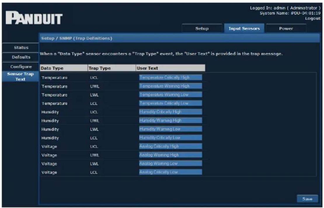
Enter text to be displayed for each type of trap.
Power
When the Power module is selected, the following menu items appear along the left-hand side of the display.
- Status
- Branch Monitoring (if the unit has breakers)
• Status 3-Phase (if the unit is 3-Phase) - Thresholds
- Configure
Status Single-Phase
The Status screen displays information from a connected Single-Phase Power Device.
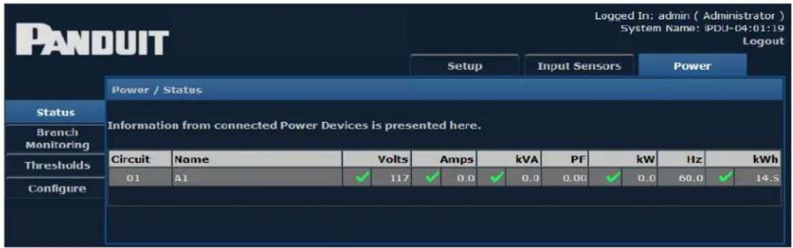
Branch Monitoring
If the power device has breakers, you will see the Branch Monitoring button as shown below. Clicking the Branch Monitoring button brings up the following screen, displaying information from branch monitoring.
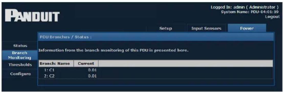
Status 3-Phase
If the device is 3-Phase, you will see the 3-Phase Status button as shown below. The 3-Phase Status screen displays information from a connected 3-Phase Power Device.
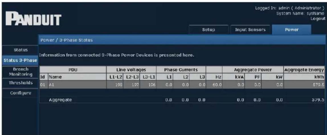
Many of the following pages use abbreviations for various units. A reference table is provided below for convenience.
| Units of Measurement | ||
| Current Amps Amperes | ||
| Power | kVA Kilovolt amperes | |
| PF Power Factor | ||
| kW Kilowatts | ||
| Frequency Hz | Hertz | |
| Energy | kWh Kilowatt hours | |
| kVArh Kilovolt amperes reactive hours | ||
Thresholds
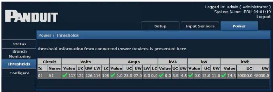
The Thresholds screen displays threshold information from a connected Power Device.
Configure
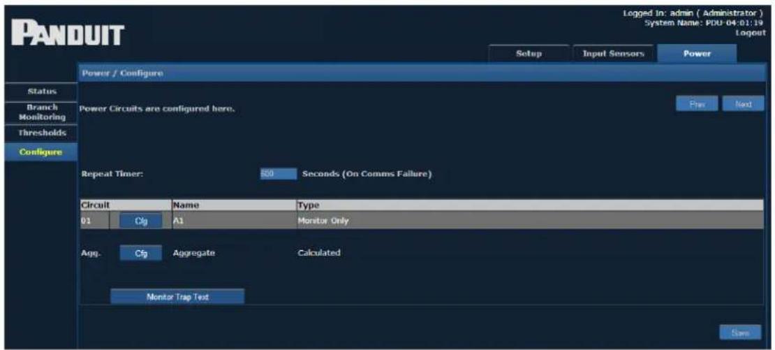
The Configure page allows you to view and configure Power Circuits. Depending on the type of unit, not all menu items shown below may be available.
Clicking the configuration button – Cfg – for a circuit brings up a screen similar to the following.
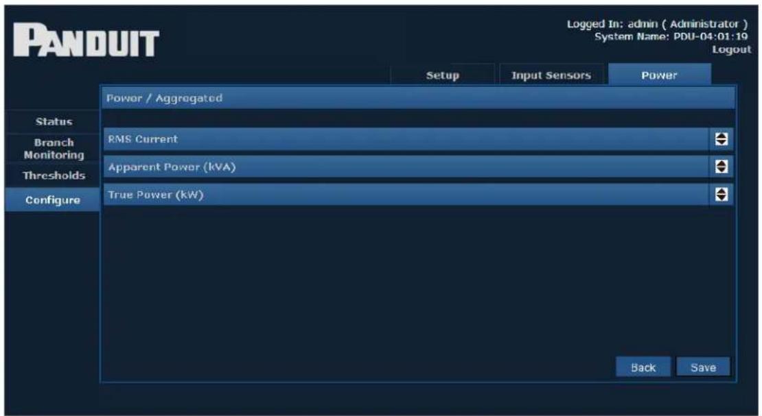
Clicking on the arrows next to each option opens a drop-down similar to the following:
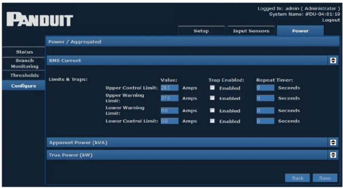
Explanations of the editable fields within the drop-down menus can be found in the table below.
| Configure Power Circuits | |
| Circuit Name The | name of the chosen circuit. |
| Upper Control Limit | The value at which an Upper Control alarm will be issued. |
| Upper Warning Limit | The value at which an Upper Warning alarm will be issued. |
| Lower Warning Limit | The value at which a Lower Warning alarm will be issued. |
| Lower Control Limit | The value at which a Lower Control alarm will be issued. |
| Trap Enabled | When the box is checked, enables the unit to send traps relating to the corresponding limit. |
| Repeat Timer | This entry (in seconds) determines how often repeat traps will be generated if the error condition persists. |
| Upper Threshold Limit | The value at which a “High” alarm will be issued. The default value is 1.00. This value applies to Power Factor only. |
| Lower Threshold Limit | The value at which a “Low” alarm will be issued. The default value is 0.01. This value applies to Power Factor only. |
The drop-down menus can be closed by clicking the corresponding arrows again.
Clicking the Monitor Trap Text button brings up screen to customize the text displayed for each trap type.
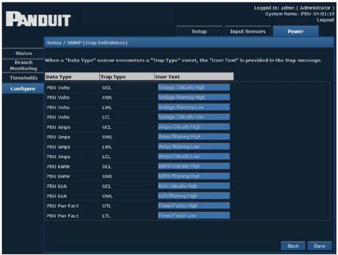
Enter the desired text in the text box provided, and click the Save button to implement your customization.
- SmartZone™ Network-Enabled M Series Rack PDU
- Table of Contents
- SmartZone™ Network-Enabled M Series Rack PDU 5
- Equipment Overview 7
- Pre-Installation ..10....
- Installation ..11....
- Mounting 17
- Hardware 22
- Graphical User Interface 25
- Setup 28
- Contacting Panduit
- Symbols Used
- Equipment Overview
- Model Numbering Format
- Model Numbers
- Pre-Installation
- Product Inspection
- Installation
- Before You Begin
- Standard Accessories
- Mounting Hardware:
- Cables/Adapters:
- Hardwire PDU installation instructions
- Unterminated Cord PDU installation instructions
- Optional Accessories
- SmartZone Environmental Sensors:
- Additional Required Items
- Safety Precautions
- Servicing
- Product Safety Warnings
- Rules
- Environmental Specifications
- Bonding
- Mounting
- Vertical Mounting
- PDU Bracket for 2-Post Racks
- Installation Instructions-Outer Mounting Brackets
- Installation Instructions-Inner Mounting Brackets
- Horizontal Mounting
- Hardware
- LCD Display
- Reset Button
- Mode Button Operation
- Bootloader Startup
- Firmware Recovery Mode
- Application Startup
- Internal Error Notification
- Graphical User Interface
- Access the PDU Graphical User Interface
- Setup
- IP Config
- IPv4 Address Configuration
- The DHCP configuration (Dynamic Addressing provided by Infrastructure)
- Static Configuration (Manual Addressing)
- IPv6 Address Configuration
- AutoConfig only (link local addressing)
- DHCPv6 configuration (dynamic addressing provided by infrastructure)
- Accessing the appliance via a web browser using IPv6
- HTTP
- SNMP NMS
- SNMP Receivers
- SNMP Trap Description Text Format
- Users
- Email Alerts
- Time Settings
- Time Adjustments
- Syslog Servers
- Events
- Preferences
- Restart
- Input Sensors
- Status
- Defaults
- Configure
- Sensor Trap Text
- Power
- Status Single-Phase
- Branch Monitoring
- Status 3-Phase
- Thresholds
Brand : Panduit
Model : SmartZone
Category : Bloc d'extension