
EKDICMPAL - Controller DAIKIN - Free user manual and instructions
Find the device manual for free EKDICMPAL DAIKIN in PDF.


| Product Type | Intelligent Chiller Manager (iCM) Controller |
| Model | EKDICMPAL |
| Dimensions (L x H x W) | 600 x 800 x 300 mm |
| Weight | 40 kg |
| Power Supply | 1-phase, 50-60 Hz, 230 VAC +/-10% |
| Output Voltage | 24 VAC |
| Nominal Current | 40 A |
| Peak Current | 10 kA |
| Power Consumption | Max 161 VA, typical 150 VA |
| IP Rating (External/Internal) | IP66 / IP20 |
| IK Rating | IK08 |
| Operating Temperature | -20 to 60 °C |
| Storage Temperature | -40 to 70 °C |
| Humidity | <90% RH (non-condensing) |
| Communication Interfaces | Modbus RTU/RS485, BACnet/IP, IP Service (Ethernet) |
| Main Functions | Chiller sequencing, pump control, bypass valve control, temperature setpoint, alarming, remote monitoring via Daikin On Site |
| HMI Options | Built-in LCD, Remote HMI, Web HMI |
| Max Chillers Supported | Up to 8 |
| Maintenance | Clean exterior with dry cloth; avoid water ingress; check connections periodically |
| Safety Precautions | Installation by qualified personnel only; disconnect power before servicing; comply with local electrical codes |
| Spare Parts / Repairability | Contact Daikin representative for spare parts; replace only with approved components |
Frequently Asked Questions - EKDICMPAL DAIKIN
User questions about EKDICMPAL DAIKIN
0 question about this device. Answer the ones you know or ask your own.
Ask a new question about this device
Download the instructions for your Controller in PDF format for free! Find your manual EKDICMPAL - DAIKIN and take your electronic device back in hand. On this page are published all the documents necessary for the use of your device. EKDICMPAL by DAIKIN.
USER MANUAL EKDICMPAL DAIKIN
Intelligent Chiller Manager (iCM)
Revision History
| Version | Date | iCM version | Remarks |
| 1.0 | 2016/4/21 | iCM_AM_Ver1.00 | First version |
| 2.0 | 2017/2/3 | iCM_Ver2.00-00.03 | Available for Air/Water-Cooled Chillers |
Index
Revision History 1
Index 3
-
Introduction 6
-
Functional Overview of iCM....7
2.1. System Topology 7
- Technical Overview....9
3.1. Electrical Panel 9
3.2. Controllers 10
3.2.1. Main Controller....10
3.2.2. BACnet Module (Optional)....11
3.2.3. MODbus Module (Optional)....11
3.2.4. I/O Modules....11
3.3. I/O Mapping ....11
3.4. Networks....11
3.4.1. Modbus® / RS485 (Chiller Network)....11
3.4.2. BACnet....11
- Electrical Installation 15
4.1. General specifications....15
4.2. Operator's responsibility ....15
- Mechanical Installation....16
5.1. Control Panel installation 16
5.2. Temperature sensor installation....17
5.3. Differential Pressure sensor installation....17
- Description of Operation....19
6.1. Menu Structure 19
6.2. Basic Parts and Operation 21
6.3. LCD Panel Display....22
6.4. Setting Address of Extension I/O Modules 24
6.5. Password Protection....25
- Scenario of Interaction 26
7.1. Workflow for Initial Configuration / Commissioning....26
7.1.1. On Site 26
7.1.2. Off Site 27
7.2. Workflow for Monitoring 28
7.2.1. Status Monitoring....28
7.2.2. Alarm Monitoring 28
7.3. Workflow for Operation 29
7.3.1. Commanding....29
7.3.2. Parameter Tuning....29
7.4. Workflow for Maintenance....30
7.4.1. Equipment Maintenance....30
7.4.2. HVAC System Component Change....30
- Configuration....31
8.1. Password Input....31
8.2. Setting System to Config Mode....32
8.3. System Configuration Setting....34
8.3.1. Setting Unit....34
8.3.2. Setting Current Time / Date 36
8.3.3. Changing Network Setting of Main Controller 36
8.3.4. Changing Network Setting of BACnet Module 38
8.3.5. Changing Network Setting of Daikin On Site (DoS: Cloud Connection) .....40
8.3.6. Showing information of iCM....41
8.4. Equipment Registration....42
8.4.1. Chiller Registration 44
8.4.2. PrimaryPump Registration....45
8.4.3. CondenserPump Registration....45
8.4.4. CTBypassValve Registration 46
8.4.5. Sensors Registration 47
8.4.6. ExtI/O Registration 48
8.4.7. BACnet_Module Registration....49
8.5. Equipment Configuration....50
8.5.1. System Configuration 52
8.5.2. Chiller Configuration 52
8.5.3. Evaporator Shut Off Valve Configuration 54
8.5.4. Condenser Shut Off Valve Configuration 54
8.5.5. Primary Pump Configuration....55
8.5.6. Condenser Pump Configuration....56
8.5.7. Sensor Configuration....57
8.5.8. Modbus Communication Setting 61
8.5.9. Ai Threshold Setting 63
- Equipment Control Setting 64
9.1. Chiller Control Setting 66
9.1.1. Setting sequence order when using fixed order sequencing....68
9.1.2. Setting detailed options for staging up / down....68
9.2. Primary Pump Control Setting....71
9.2.1. Setting PI Parameters for Pump VFD Control....72
9.2.2. Setting periodical pump staging for rotation....73
9.2.3. Setting minimum / maximum number of operating pumps for each piping group 73
9.3. Bypass Valve Control Setting....74
9.3.1. Setting PI Parameters for Bypass Valve Control....75
9.4. Condenser Pump Control Setting....75
9.4.1. Setting DT_PI Parameters for Pump VFD Control....77
9.4.2. Setting DP_PI Parameters for Pump VFD Control....77
9.4.3. Setting minimum / maximum number of operating pumps for each piping group 78
9.5. Cooling Tower Bypass Valve Control Setting....79
9.5.1. Setting PI Parameters for Cooling Tower Bypass Valve Control 80
9.6. System Control Setting 81
9.6.1. Power Failure Recovery 82
9.6.2. Protect System 83
9.6.3. Double Temperature Setpoint....84
9.6.4. Pull Down Rate Control 85
9.6.5. Setpoint reset 86
9.7. Source of Input Setting 88
- Trial Run 91
10.1. Chiller Trial Run....93
10.2. I/O Trial Run 93
10.3. BACnet Module Trial Run 100
-
Saving / Loading Configuration Data....101
-
Monitoring....103
12.1. Showing Current Status of System 103
12.2. Showing Current Status of Chillers 104
12.2.1. Showing the overview of chillers....104
12.2.2. Showing the detailed view of chillers 105
12.3. Showing Current Status of Evaporator Side Shut Off Valve 106
12.3.1. Showing the detailed view of Evaporator Side Shut Off Valve 106
12.4. Showing Current Status of Condenser Side Shut Off Valve 107
12.4.1. Showing the detailed view of Condenser Side Shut Off Valve 107
12.5. Showing Current Status of Primary Pumps....108
12.5.1. Showing the detailed view of Primary Pumps 108
12.6. Showing Current Status of Bypass Valve....109
12.7. Showing Current Status of Condenser Pumps 109
12.7.1. Showing the detailed view of Condenser Pumps....109
12.8. Showing Current Status of Cooling Tower Bypass Valve 110
12.9. Showing Current Status of Sensors 110
12.10. Showing Current Status of I/O 111
12.11. Showing Current Status of Controls....111
12.11.1. Show current status of chiller control 112
12.11.2. Show current status of primary pump control....112
- Operation....113
13.1. Basic Commanding....113
13.2. Resetting emergency stop 114
13.3. Setting Chillers to "Maintenance" 115
- Alarming....117
14.1. Showing Current List of Alarms....117
14.2. Showing History of Alarms....118
14.3. Deleting History of Alarms....119
14.4. Resetting Alarms 120
- APPENDIX – Alarms....123
15.1. Alarm Codes....123
15.1.1. Alarm for the chiller system 123
15.1.2. Alarms for individual equipment....126
-
APPENDIX – BACnet Integration Data (Main Controller) 127
-
APPENDIX – HMI Monitoring and Command....128
-
APPENDIX - I/O Mapping....130
-
APPENDIX – Compatibility List .....139
-
APPENDIX – Integrated Modbus Points....140
20.1.Global chillers....140
20.2. U.S. Chillers....141
1. Introduction
READ THIS MANUAL CAREFULLY BEFORE INSTALLING AND STARTING UP THE UNIT. IMPROPER INSTALLATION COULD RESULT IN ELECTRIC SHOCK, SHORT-CIRCUIT, LEAKS, FIRE OR OTHER DAMAGE TO THE EQUIPMENT OR INJURE TO PEOPLE. THE UNIT MUST BE INSTALLED BY A PROFESSIONAL OPERATOR/TECHNICIAN UNIT STARTUP HAS TO BE PERFORMED BY AUTHORIZED AND TRAINED PROFESSIONAL ALL ACTIVITIES HAVE TO BE PERFORMED ACCORDING TO LOCAL LAWS AND REGULATION. UNIT INSTALLATION AND START UP IS ABOSOLUTELY FORBIDDEN IF ALL INSTRUCTION CONTAINED IN THIS MANUAL ARE NOT CLEAR. IF CASE OF DOUBT CONTACT THE MANUFACTURER REPRESENTATIVE FOR ADVICE AND INFORMATION.
2. Functional Overview of iCM
2.1. System Topology
The system topology for the package of iCM is described below.
Table 1 - Equipment overview
| Availability | Drive | Piping | Cooling type | ||||
| CSD | VFD | Manifolded | Dedicated | Air-cooled | Water-cooled | ||
| Chiller | Yes | Yes | Yes | - | - | Yes | Yes |
| Evaporator pumps | Yes | Yes | Yes | Yes | Yes | - | - |
| Shut-off valves (evaporator side) | Yes | - | - | - | - | - | - |
| Bypass valve (evaporator side) | Yes | - | - | - | - | - | - |
| Condenser pumps | Yes | Yes | Yes | Yes | Yes | - | - |
| Shut-off valves (condenser side) | Coming Soon | - | - | - | - | - | - |
| Bypass valve (condenser side) | Coming Soon | - | - | - | - | - | - |
CSD: Constant Speed Driver
VFD: Variable Frequency Driver
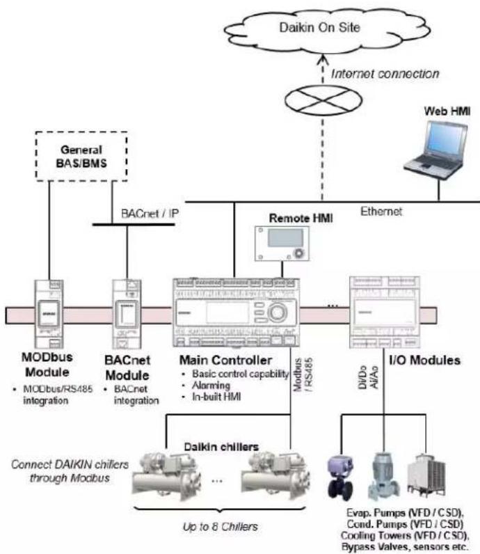
flowchart
graph TD
    A["Daikin On Site"] -->|Internet connection| B["Internet"]
    B --> C["Web HMI"]
    C --> D["Ethernet"]
    D --> E["Remote HMI"]
    E --> F["Modbus / RS485"]
    F --> G["I/O Modules"]
    G --> H["Dalkin chillers"]
    H --> I["Up to 8 Chillers"]
    I --> J["Connect DAIKIN chillers through Modbus"]
    K["General BAS/BMS"] --> L["BACnet / IP"]
    L --> M["Modbus Module"]
    N["Modbus / RS485 integration"] --> O["BACnet module"]
    P["Main Controller"] --> Q["Basic control capability"]
    P --> R["Alarming"]
    P --> S["In-built HMI"]
    T["DiDc AlAc"] --> U["I/O Modules"]
    V["Evap. Pumps (VFD / CSD), Cond. Pumps (VFD / CSD) Cooling Towers (VFD / CSD), Bypass Valves, sensors etc."] --> W["Modbus / RS485"]
Figure 1 - System Topology of iCM
☐ BACnet / IP connectivity is offered through BACnet Module for integration with general BAS/BMS
☐ Built-in HMI, Remote HMI and Web HMI (on Daikin on Site; DoS) is available for monitoring and configuration
From main controller, connectivity to "Daikin on Site" (DoS: Cloud platform), remote monitoring and service
3. Technical Overview
iCM (intelligent Chiller manager) consists of:
Electrical Panel
☐ Temperature sensors
☐ 3G router for internet connectivity
☐ Optional devices:
o Communication modules for BMS integration
- By-pass valve on primary loop
3.1. Electrical Panel
Table 2 Electrical panel technical data
| EKDICMPAB | EKDICMPAL | EKDICMPAF | ||
| Environmental conditions | Operating air temperature | -20...60°C | ||
| Storage temperature | -40...70°C | |||
| Humidity | <90%Rh (without condensation) | |||
| Air pressure | min. 700KPa, corresponding to max. 3000m above sea level | |||
| Dimension | Panel | Metal | ||
| External door | N/A | Lexan | ||
| Internal door | Metal with lamps | Metal with HMI and lamps and three position selector | ||
| Size (L x H x W) | 500x700x250 | 600x800x300 | 800x1000x300 | |
| Weight | 30Kg | 40Kg | 50Kg | |
| IP Code (International protection) | IP54 (external) | IP66 (external) | IP66 (external) | |
| IP20 (internal) | IP20 (internal) | IP20 (internal) | ||
| IK Code (mechanical protection) | IK08 | |||
| Power Supply | Phase | 1 phase | ||
| Frequency | 50...60 Hz | |||
| Input Voltage | 230 VAC +/- 10% | |||
| Output Voltage | 24VAC | |||
| Nominal Current | 40A | |||
| Peak Current | 10kA | |||
| Power Consumption | Controller + Modules | Max: 161 VATypical: 150 VA | ||
| Communications | MODbus RTU for chiller network | RS-485: | ||
3.2. Controllers
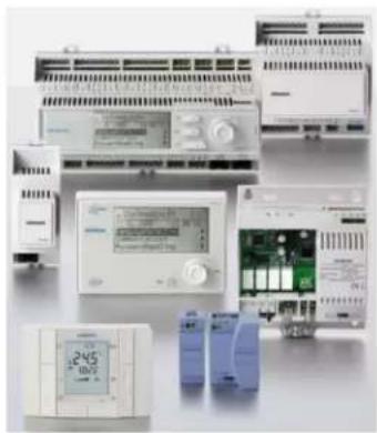
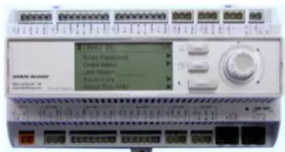
With the Microtech III family of controllers, Daikin offers maximum flexibility in the control and monitoring of chiller plant systems. Comprehensive system functions such as alarm management, time scheduling and trend data storage cover all requirements associated with the operation of a chiller plant room system.
□ Main controller
☐ Daikin on Site (DoS) through IP Service Port and internet connectivity
☐ Daikin Chiller Management through in-built MODbus RTU/RS485
☐ Integration by BMS (Building Management Station)
BACnet communication module
MODbus communication module
□ I/O modules
natural_image
Collection of electronic devices including PLCs, relays, and control panels (no visible text or labels)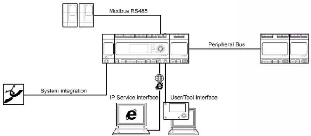
flowchart
graph TD
    A["Modbus RS485"] --> B["Peripheral Bus"]
    C["System integration"] --> D["IP Service interface"]
    D --> E["User/Tool Interface"]
    B --> F["Computer with 'e'"]
    E --> G["Computer with 'e'"]
    F --> H["Computer with 'e'"]
    G --> I["Computer with 'e'"]
Figure 2 Controller architecture
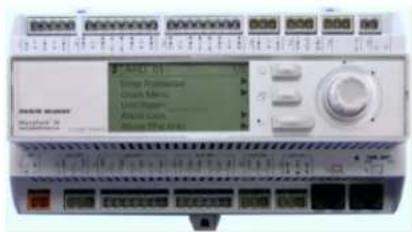
3.2.1. Main Controller
The main controller provide the following functions
□ Control functions
□ Built-in HMI for monitoring and setting
☐ Onboard Modbus / 485 for connection with Chiller Modbus network as Master device.
☐ Onboard IP Service Interface port for connection with Ethernet network
Onboard I/O's
☐ Provision for adding extension I/O modules
☐ Provision for adding communication modules
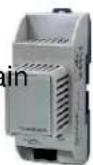
3.2.2. BACnet Module (Optional)
The BACnet module provides BACnet / IP integration when connected to the main controller.
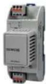
3.2.3. MODbus Module (Optional)
The MODbus module provides Modbus RTU/ RS-485 integration as Slave device when connected to the main controller.
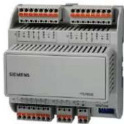
3.2.4. I/O Modules
The I/O modules provide additional I/O points by connecting to the main controller sensors, valve actuators, pumps and cooling towers are connected through the I/O module. The types of I/O points include the following.
☐ Analog Outputs: 4-20mA
☐ Analog Inputs: NTC 10K
☐ Digital Outputs: Potential free contacts (Non-Voltage)
☐ Digital Inputs are: Potential free / Potential contacts (Voltage)
The number of I/O modules needed varies depending on the system configuration..
natural_image
Exterior view of a Siemens industrial control unit (no visible text or symbols on the device body)3.3. I/O Mapping
The mapping of I/O's on the main controller and the extension I/O modules is predefined. You can find the full list of I/O mapping in the appendix to this document (18 APPENDIX - I/O Mapping)
3.4. Networks
There are three communication Networks in the iCM:
Modbus® / RS485 for the integration of chiller data into the iCM controller
☐ BACnet / IP or Modbus®RTU / RS485 for the connection between the iCM controller and a general BAS/BMS
☐ IP Service interface over Ethernet for communication with Daikin on Site through Internet connection.
3.4.1. Modbus® / RS485 (Chiller Network)
The data residing in the chillers are integrated into the iCM controller using Modbus® / RS485. The set of Modbus® data point varies slightly with the chiller type. iCM has Modbus data map for Daikin global standard chillers pre-included, allowing for easy Modbus / RS485 connection through just simple configuration. (19 APPENDIX – Compatibility List)
In the appendix of this document you will find an overview of which Modbus® points that are integrated into the iCM (20 APPENDIX – Integrated Modbus Points)
3.4.2. BACnet
For general integration of the iCM and a BAS/BMS workstation, BACnet is available.
You can find the full list of BACnet points for iCM in the appendix to this document (16 APPENDIX – BACnet Integration Data (Main Controller)) Modbus®
For general integration of the iCM and a BAS/BMS workstation, MODbus RTU can be provided under request.
Providing an internet connectivity to the controller through onboard IP service interface, it is possible to take advantage of the Daikin On Site service.
Daikin On Site makes use of the benefits offered by the cloud technology that allows remote access and servicing at any time from any location. All data from the system plant-room are constantly collected and automatically stored in the cloud server. Customer can access and
☐ monitor in real time the system through a graphical interface
☐ manage the stored data to create trend
☐ download the data from the server.
Daikin On site permits system diagnostic in real time, simple maintenance, energy efficiency evaluation and optimization.
3.5. Human Machine Interface (HMI)
Depended on the sold solution the system comes with one or more of the following HMI's:
□ Built-in HMI on the controller
Remote HMI
WEB HMI
You can find the list of points that can be monitored and commanded from the HMI in the appendix (17 APPENDIX – HMI Monitoring and Command)
NOTE: Remote HMI is not provided with EKDICMPAB
3.5.1. Built-in HMI
Built-in HMI is the HMI directly on the iCM main controller. Built-in HMI is capable of full operation of the iCM.
It has an LCD display for text and icons. The push dial and buttons allows for easy operation.
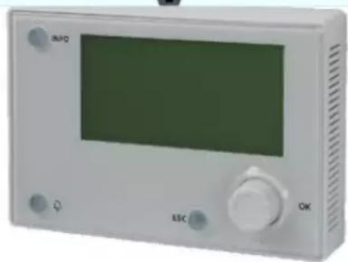
3.5.2. Remote HMI
The Remote HMI is capable of full operation and configuration of the iCM.
The remote HMI has a high-resolution illuminated LCD display for text and graphics, push dial and buttons for operation, and a common alarm indicator.
The Remote HMI can be mounted e.g. in the operators office or at the iCM panel door.
natural_image
Front view of a white electronic device with a green screen and control buttons (no visible text or symbols)3.5.3. Web HMI
With its integrated Internet technology, the embedded Web server allows full plant operation of the iCM using standard Web browsers.
3.6. Temperature sensors
Two immersion temperatures sensors are included in the kit to measure the entering and leaving water temperature of the system.
Table 3 Temperature sensors technical data
| Technical data | Type | Immersion temperature sensor |
| Sensing element | NTC10K | |
| Immersion length | 100mm | |
| Functional data | Measuring rate | -30...125°C |
| Time constant | 30s | |
| Accuracy | Refer to sensor datasheet | |
| Nominal pressure | PN16 | |
| Degree of protection | Protection class | III according to EN 60730-1 |
| Electrical connections | Screw terminals | 1 x 2,5 mm ^2 or 1,5 mm ^2 |
| Connections | Interchangeable | |
| Environmental conditions | Operation | Class 3K5 |
| Temperature | -25...70°C | |
| Humidity | 5...95% r.h. |
3.7. Wireless Router
Providing internet connectivity to the controller, it is possible to start the Daikin on Site service for remote monitoring and data storing.
The 3G router is part of the iCM standard package.
Table 4 Wireless Router technical data
| Technical data | Wireless 3G Modem | VODAFONE MachineLink_3G |
| RF Antenna | PANORAMA ANTENNAS MAR-7-21-2SP | |
| Connections | RJ45 Ethernet | 10/100 base T |
| Power supply | MEAN WELL | 10W AC/DC |
| Input Voltage | 115/230VAC | |
| Output Voltage | 12VDC | |
| Environmental conditions | Ambient temperature | -30...70°C |
| Ambient humidity | 90% r.h. @ 60°C |
3.8. Differential Pressure sensor (Optional)
In case of primary loop variable flow and consequently control of variable frequency driver on the primary pumps, a differential pressure sensor must be installed in the chiller plant-room to allow iCM perform the correct control logic.
Table 5 Differential Pressure Sensor Technical data
| Technical data | Type | Differential pressure sensor |
| For neutral or midly corrovise liquids | ||
| Measuring element | Ceramic | |
| Functional data | Measuring range | 0...1.6 bar0...2.5 bar0...4 barAccording to requested range |
| Accuracy | 0.1% Full scale | |
| Response time | <5ms | |
| Admissible temperature of medium | -15...80°C | |
| Operating voltage | DC 11...33V | |
| Output signal | DC 4...20mA | |
| Degree of protection | Protection class | IP65 |
| Connection | Electrical cable | Plug with seals and PG9 cable glands included |
| Pressure connections | Male-threaded G1/8" with screwed fitting for copper pipes, 6mm diameter | |
| Environmental condition | Ambient temperature | -15...85°C |
| Ambient humidity | <95% r.h. (non-condensing) |
4. Electrical Installation
4.1. General specifications
All electrical connections to the unit must be carried out in compliance with laws and regulations in force.
All installation, management and maintenance activities must be carried out by qualified personnel.
Refer to the specific wiring diagram for the unit you have bought. Should the wiring diagram not be on the control panel or should it have been lost, please contact your manufacturer representative, who will send you a copy.
In case of discrepancy between wiring diagram and electrical panel/cables, please contact the manufacturer representative.
Only use copper conductors. Failure to use copper conductors could result in overheating or corrosion at connection points and could damage the control panel.
To avoid interference, all control wires must be connected separately from the power cables. Use different electrical passage ducts for this purpose.
Particular care must be taken when realizing wire connections to the switchbox; if not properly sealed, cable entries may allow ingress of water into the switchbox which may cause damage to the equipment inside.
Before any installation and connection works, the unit must be switched off and secured.
This product complies with EMC standards for industrial environments. Therefore it is not intended for use in residential areas, e.g. installations where the product is connected to a low voltage public distribution system. Should this product need to be connected to a low voltage public distribution system, specific additional measures will have to be taken to avoid interference with other sensitive equipment.
4.2. Operator's responsibility
It is essential that the operator is appropriately trained and becomes familiar with the system before operating the panel. In addition to reading this manual, the operator must study the databook for functional overview and the wiring diagram in order to understand start-up sequence, operation, management of the peripherals connected to the control panel.
5. Mechanical Installation
5.1. Control Panel installation
Control panel can be installed free standing taking care of the following minimum clearance requirements:
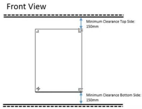
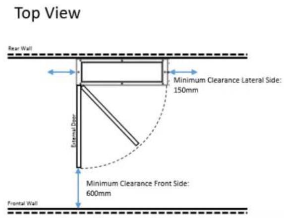
Figure 3 Minimum Clearance Requirements
Cable entry hole is on the bottom side of the panel
NOTE: dimension of the external door are shown in Table 2 Electrical panel technical data
For the hanging installation on a wall, please use the brackets shown in the following picture, provided with panel:
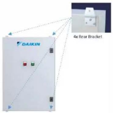
Figure 4 Brackets position
NOTE: Weight of different sizes of the panel are shown in Table 2 Electrical panel technical data
5.2. Temperature sensor installation
The sensors should be located on the supply header and on return header.
The location should be chosen such that the water must be well mixed where the temperature is acquired.
The sensor should be mounted such that the cables does not enter from the top (only by side).
The immersion length must be at least 60mm.
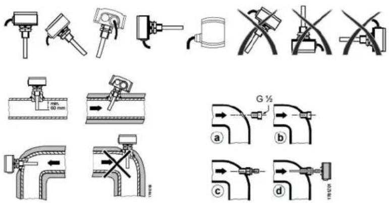
Figure 5 Temperature sensor mounting
For more information, please refer to datasheet and installation guide provided with sensor.
5.3. Differential Pressure sensor installation
Differential pressure sensors must be mounted between the inlet and outlet water pipes of the furthest load in the system.
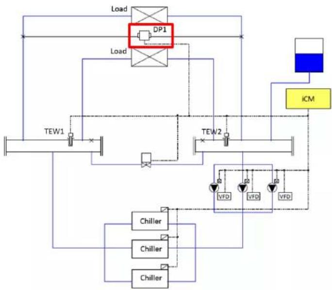
flowchart
graph TD
    A["Load"] --> B["DP1"]
    B --> C["TEW1"]
    B --> D["TEW2"]
    C --> E["Chiller"]
    D --> F["Chiller"]
    E --> G["Chiller"]
    F --> H["Chiller"]
    G --> I["VFD"]
    H --> J["VFD"]
    I --> K["VFD"]
    J --> L["VFD"]
    M["iCM"] --> N["Control Unit"]
    style A fill:#f9f,stroke:#333
    style M fill:#bbf,stroke:#333
Figure 6 Differtial pressure sensor position
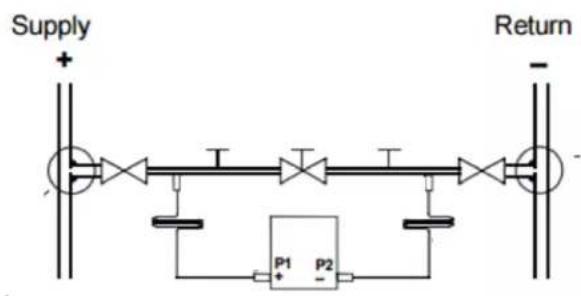
The sensor must be always mounted lower than the pressure measuring points.
flowchart
graph LR
    A["Supply"] --> B["Process Unit 1"]
    B --> C["Return"]
    D["P1"] --> E["Feedback Loop"]
    E --> F["P2"]
    F --> G["Output"]
    style A fill:#f9f,stroke:#333
    style G fill:#bbf,stroke:#333
Figure 7 DP Sensor mounting
For detailed information, please refer to the datasheet and installation guide provided with sensor.
6. Description of Operation
6.1. Menu Structure
The menu structure of iCM is described below.
□ Status
○ Command
Emergency Stop Reset
○ Chiller Status
- Chiller#01 Detail
...
- Chiller#08 Detail
- EvShutOffValve Status
- EvSO_Valve01 Detail
...
- EvSO_Valve08 Detail
○ CndShutOffValve Status
- CndSO_Valve01 Detail
...
- CndSO_Valve08 Detail
o Primary Pump Status
■ Primary Pump#01 Detail
...
■ Primary Pump#08 Detail
○ Bypass Valve Status
- CondenserPump Status
- CondenserPump01 Detail
...
- CondenserPump08 Detail
- CTBypassValve Status
- Sensors Status
- I/O Status
- Control Status
- ChillerCtrl Status
- PriPpCtrl Status
Setting
- System Control Parameters
■ Double Temperature Setpoint
■ Pull Down Rate Control
■ Power Failure Recovery
- SetptReset
- Protect System
○ Device Control Parameters
- Chiller Control
■ Primary Pump Control
■ Bypass Valve Control
- CondenserPump Control
- CTBypassValve Control
- Control Mode Setting
- System Setting
- Date/Clock
Network
- Main NetworkSetting
- BACnet NetworkSetting
• Daikin On Site Status
• HMI for Web Setting
- About
□ Config Mode
○ Device Config
- System Config
- Chiller Config
■ Primary Pump Config - Sensors Config
■ Modbus Comm. Setting
○ Trial Run
- Chiller Trial Run
■ I/O Trial Run (#1 to #17)
○ Device Registration
- Chiller Registration
■ Primary Pump Registration
■ CondenserPump Registration
■ CTBypassValve Registration - Sensors Registration
■ ExtI/O Registration
- Backup/Restore
- Data Management
\*Special menus
Password
- Enter Password
□ Alarm entry
○ Alarm List overview
- Alarm History overview
6.2. Basic Parts and Operation
Basic parts and operation of iCM controller are described below.
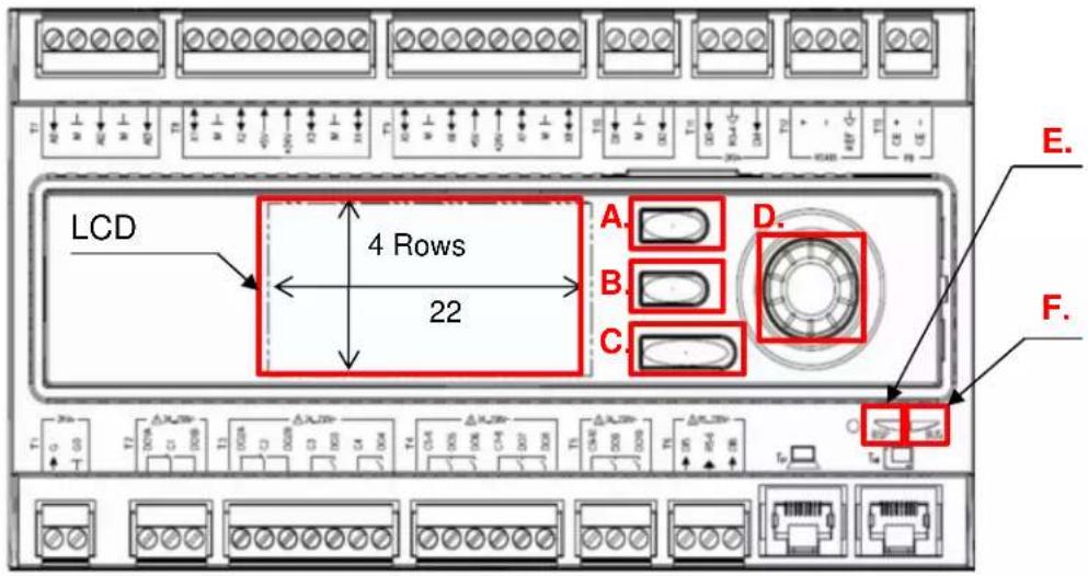
Figure 8 - Controller description
A) Alarm Button: Used to jump to "Alarming" Screen
B) Home Button: Used to jump to "MainMenu" Screen
C) Back Button: Used to go back one screen or Discard input value
D) value Click-dial: Turn: Select Next/Previous row or Change input
Push: Jump to linked page or Validate input value
*When using the click-dial, turning the dial faster enables bigger digit of input value to change.
E) BSP Indicator LED:
This LED indicates the status of the controller
| Mode | LED status |
| SW update mode (download active on a new BSP, application) | Every second alternating between red and yellow |
| Application running | Green on |
| Application loaded but not running | Yellow on |
| Application not loaded | Yellow flashing (50 ms on, 1000 ms off) |
| BSP error (software error) | Red blinking at 2 Hz |
| Hardware error | Red on |
F) Bus Indicator LED: This LED only indicates the status of the integrated modem communication.
| Mode | LED status |
| No modem connected, or LED disabled | Off |
| Modem connected and initialized no communication active | Yellow on |
| Modem connected and communication active | Green on |
| Modem connected but errors active (like provider missing, no initialization possible) | Red on |
| BSP error (software error) | Red blinking at 2Hz |
| Hardware error | Red on |
6.3. LCD Panel Display
Below, basic composition of LCD panel display is explained.
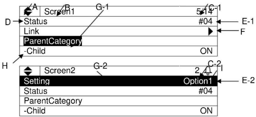
flowchart
graph TD
    A["Screen1"] --> B["5-14"]
    C["ParentCategory"] --> D["#04"]
    E["Option1"] --> F["E-1"]
    G["Link"] --> H["F"]
    I["Screen2"] --> J["C-2"]
    K["Setting"] --> L["Option1"]
    M["Status"] --> N["#04"]
    O["ParentCategory"] --> P["ON"]
A. Hidden row indicator
▼ : Hidden rows exist below
◆ : Hidden rows exist below and above
▲ : Hidden rows exist above
B. Screen title
Title of the currently displayed screen
C. Row number
C-1) Current row / Available rows on each screen is displayed
C-2) Only current row is shown when alarm sign 📄s displayed
D. Item name
Item name is displayed on the left side
E. Value
Current status or setting is displayed on the right side.
E-1) Unchangeable values display the status
E-2) Changeable values can be modified by selecting the row then clicking on the click-dial

F. Link
: Link to another page available. You can jump to the linked page by clicking on the click-dial
G. Current row
Currently selected row is shown with inverted cursor. The cursor can be moved by turning the click-dial
G-1) Only item name or “-” character is inverted for rows with unchangeable value
G-2) Whole row is inverted for rows with changeable value
H. Hierarchy
Item name with “-” indicate that it is a child of the above item.
I. Alarm
Alarm sign ☐s shown when there is an active alarm. You can check the details of the alarm by pushing the alarm button ☐
6.4. Setting Address of Extension I/O Modules
For each extension I/O module, predefined address needs to be set via DIP switches on the modules as shown below.
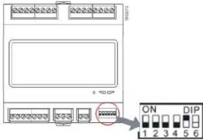
Figure 9 - DIP Switches
Table 6 DIP Switch Setting
| Name | Addr. | DIP switch setting | |||||
| Switch1 | Switch2 | Switch3 | Switch4 | Switch5 | Image | ||
| Ext. Module1P.P.1PrimPmp 1-2 | 1 | OFF | OFF | OFF | OFF | ON | 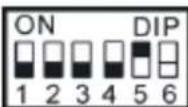 |
| Ext. Module2P.P.2PrimPmp 3-4 | 2 | OFF | OFF | OFF | ON | OFF | 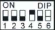 |
| Ext. Module3P.P.3PrimPmp 5-6 | 3 | OFF | OFF | OFF | ON | ON | 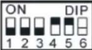 |
| Ext. Module4P.P.4PrimPmp 7-8 | 4 | OFF | OFF | ON | OFF | OFF | 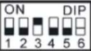 |
| Ext. Module5S.V.1ShutOffVlv 1-4 | 5 | OFF | OFF | ON | OFF | ON | 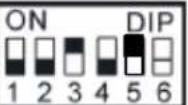 |
| Ext. Module6S.V.2ShutOffVlv 5-8 | 6 | OFF | OFF | ON | ON | OFF | 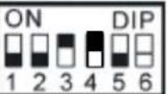 |
| Ext. Module9CW.Sns.1CoolingSns 1-2 | 9 | OFF | ON | OFF | OFF | ON | 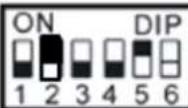 |
| Ext. Module10CW.Sns.2CoolingSns 3-4 | 10 | OFF | ON | OFF | ON | OFF | 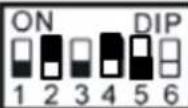 |
| Ext. Module11CW.P.1CoolingPmp 1-2 | 11 | OFF | ON | OFF | ON | ON | 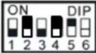 |
| Ext. Module12CW.P.2CoolingPmp 3-4 | 12 | OFF | ON | ON | OFF | OFF | 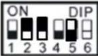 |
| Ext. Module13CW.P.3CoolingPmp 5-6 | 13 | OFF | ON | ON | OFF | ON | 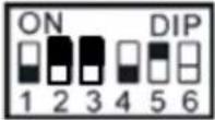 |
| Ext. Module14C.W.P.4CoolingPmp 7-8 | 14 | OFF | ON | ON | ON | OFF | 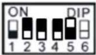 |
| Ext. Module15CW.S.V.1ShutOffVlv 1-4 | 15 | OFF | ON | ON | ON | ON | 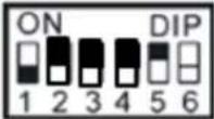 |
| Ext. Module16CW.S.V.2ShutOffVlv 5-8 | 16 | ON | OFF | OFF | OFF | OFF | 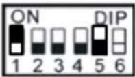 |
6.5. Password Protection
iCM has password protection functionality to avoid unauthorized changes in the setting.
7. Scenario of Interaction
Table 7 illustrates overview of workflow for working with iCM. Detail of each scenario is described in the following pages.
Table 7 Scenario of Interaction
| A. Initial configuration / Commissioning | 7.1.1 On Site |
| 7.1.2 Off Site | |
| B. Monitoring | 7.2.1 Status Monitoring |
| 7.2.2 Alarm Monitoring | |
| C. Operation | 7.3.1 Commanding |
| 7.3.2 Parameter Tuning | |
| D. Maintenance | 7.4.1 Equipment Maintenance |
| 7.4.2 HVAC System Component Change |
7.1. Workflow for Initial Configuration / Commissioning
7.1.1. On Site
Table 8 illustrates steps for initial configuration of iCM on site.
Table 8 Workflow for Initial Configuration / Commissioning On Site
| Step | Name | Description | Reference chapter |
| 1 | Password input | Input password to show service menu | 8.1 Password Input |
| 2 | Set system to Config Mode | Set system to Config Mode to enable equipment registration etc | 8.2 Setting System to Config Mode |
| 3 | System Configuration | Setting of IP address, date and time etc | 8.3 System Configuration Setting |
| 4 | Equipment registration | Registration of equipment for control from iCM | 8.4 Equipment Registration |
| 5 | Equipment Initial setting | Initial setting for each equipment | 8.5 Equipment Configuration |
| 6 | Equipment control setting | Setting of parameters for equipment control (e.g. chiller staging, pump VFD control etc) | 9 Equipment Control Setting |
| 7 | System control setting | Setting of parameters for system control (e.g. double setpoint, pull down rate control etc) | 9.6 System Control Setting |
| 8 | Source of input setting | Setting of source of input for each command | 9.7 Source of Input Setting |
| 9 | Trial run | Send command to each equipment to check connection | 10 Trial Run |
| 10 | Backup configuration | Backup configuration data to SD card | 11 Saving / Loading Configuration Data |
| 11 | Unset Config Mode | Unset system from config mode to enable system operation | 8.2 Setting System to Config Mode |
7.1.2. Off Site
Table 9 illustrates steps for initial configuration of iCM off site.
Table 9 Workflow for Initial Configuration / Commissioning Off Site
| Step | Name | Description | Reference chapter | |
| With Off-site iCM | 1 | Password input | Input password to show service menu | 8.1 Password Input |
| 2 | Set system to Config Mode | Set system to Config Mode to enable equipment registration etc | 8.2 Setting System to Config Mode | |
| 3 | System setting | Setting of IP address, date and time etc | 8.3 System Configuration Setting | |
| 4 | Equipment registration | Registration of equipment for control from iCM | 8.4 Equipment Registration | |
| 5 | Equipment Initial setting | Initial setting for each equipment | 8.5 Equipment Configuration | |
| 6 | Equipment control setting | Setting of parameters for equipment control (e.g. chiller staging, pump VFD control etc) | 9 Equipment Control Setting | |
| 7 | System control setting | Setting of parameters for system control (e.g. double setpoint, pull down rate control etc) | 9.6 System Control Setting | |
| 8 | Source of input setting | Setting of source of input for each command | 9.7 Source of Input Setting | |
| 9 | Save configuration | Save off-site configuration data to SD card | 11 Saving / Loading Configuration Data | |
| With On-site iCM | 10 | Set system to Config Mode | Set system to Config Mode to enable trial run menu | 8.2 Setting System to Config Mode |
| 11 | Load configuration | Load configuration to on-site iCM | 11 Saving / Loading Configuration Data | |
| 12 | System Configuration | Setting of IP address, date and time which could not be done off-site | 8.3 System Configuration Setting | |
| 13 | Trial run | Send command to each equipment to check connection | 10 Trial Run | |
| 14 | Backup configuration | Backup configuration data to SD card | 11 Saving / Loading Configuration Data | |
| 15 | Unset Config Mode | Unset system from config mode to enable system operation | 8.2 Setting System to Config Mode | |
7.2. Workflow for Monitoring
7.2.1. Status Monitoring
Table 10 illustrates steps for status monitoring on iCM
Table 10 Workflow for Status Monitoring
| Step | Name | Description | Reference chapter |
| 1 | Monitor Status | Monitor status of system and each equipment to find potential problems | 12.1 Showing Current Status of System12.2 Showing Current Status of Chillers12.3 Showing Current Status of EvaporatorSide Shut Off Valve12.4 Showing Current Status of CondenserSide Shut Off Valve12.5 Showing Current Status of Primary Pumps12.6 Showing Current Status of Bypass Valve12.7 Showing Current Status of CondenserPumps12.8 Showing Current Status of Cooling Tower Bypass Valve12.9 Showing Current Status of Sensors12.10 Showing Current Status of I/O |
7.2.2. Alarm Monitoring
Table 11 illustrates steps for alarm monitoring on iCM
Table 11 Workflow for Alarm Monitoring
| Step | Name | Description | Reference chapter |
| 1 | Check Alarm | Check to see which alarm is active | 14 Alarming |
| 2 | Make Corrective Actions | Make necessary changes, actions | - Not done from iCM |
| 3 | Monitor Status | Monitor status of system and each equipment to ensure the system is operating correctly | 12 Monitoring |
| 4 | Alarm Reset | Reset Alarm from iCM as needed | 14.4 Resetting Alarms |
7.3. Workflow for Operation
7.3.1. Commanding
Table 12 illustrates steps for alarm monitoring from iCM
Table 12 Workflow for commanding from iCM
| Step | Name | Description | Reference chapter |
| 1 | Source of input setting | Set source of input for desired command to manual | 9.7 Source of Input Setting |
| 2 | Command | Send various commands from HMI | 13 Operation |
7.3.2. Parameter Tuning
Table 13 illustrates steps for tuning of control parameters from iCM
Table 13 Workflow for Parameter Tuning
| Step | Name | Description | Reference chapter |
| 1 | Monitor Status | Monitor status of system and each equipment to find potential problems | 12 Monitoring |
| 2 | Password input | Input password to show service menu | 8.1 Password Input |
| 3 | Equipment control setting | Setting of parameters for equipment control (e.g. chiller staging, pump VFD control etc) | 9 Equipment Control Setting |
| 4 | System control setting | Setting of parameters for system control (e.g. double setpoint, pull down rate control etc) | 8.3 System Control Setting |
| 5 | Monitor Status | Monitor status of system and each equipment to find potential problems | 12 Monitoring |
7.4. Workflow for Maintenance
7.4.1. Equipment Maintenance
Table 14 illustrates steps for maintenance of equipment.
Table 14 Workflow for Maintenance of Equipment
| Step | Name | Description | Reference chapter |
| 1 | Set equipment as Not Available | Set equipment as “Not Available” from iCM to exclude from controls | 13.3 Setting Chillers to “Maintenance” |
| 2 | Maintenance of equipment | Do needed maintenance of equipment | - Not done from iCM |
| 3 | Set equipment as Available | After needed maintenance is done, set equipment as “Available” from iCM to be included by controls. | 13.3 Setting Chillers to “Maintenance” |
7.4.2. HVAC System Component Change
Table 15 illustrates steps for HVAC system component change.
Table 15 Workflow for HVAC System Component Change
| Step | Name | Description | Reference chapter |
| 1 | Password input | Input password to show service menu | 8.1 Password Input |
| 2 | Source of input setting | Change source of input for ON/OFF signal to manual if necessary in order to stop the system | 9.7 Source of Input Setting |
| 3 | Stop the system | Stop the system from HMI | 13 Operation |
| 4 | Set system to Config Mode | Set system to Config Mode to enable equipment registration etc | 8.2 Setting System to Config Mode |
| 5 | Equipment registration | Registration of new equipment or unregister unnecessary equipment | 8.4 Equipment Registration |
| 6 | Equipment Configuration | Initial setting for each of the new equipment | 8.5 Equipment Configuration |
| 7 | Equipment control setting | Setting of parameters for equipment control (e.g. chiller staging, pump VFD control etc) | 9 Equipment Control Setting |
| 8 | Trial run | Send command to each equipment to check connection | 10 Trial Run |
| 9 | Backup configuration | Backup configuration data to SD card | 11 Saving / Loading Configuration Data |
| 10 | Unset Config Mode | Unset system from config mode to enable system operation | 8.2 Setting System to Config Mode |
8. Configuration
Menu structure of related screens is shown below.
□MainMenu
- Password.... Input screen for password to show hidden menu
ConfigMode....Set system to Config Mode in order to do initial configuraiton
8.1. Password Input
Steps for inputting the password to show normally hidden menu are described below.
- Press the Home Button ☐ to show the "MainMenu" screen.
| MainMenu | 1/4 | |
| Status | ▶ | |
| Setting | ▶ | |
| ConfigMode | ▶ | |
| Password | ▶ | |
- On the "MainMenu" screen, turn the click-dial Ⓞ to select "Password" menu then press down on the click-dial to jump to "Password" screen.
| MainMenu | 4/4 | |
| Status | ▶ | |
| Setting | ▶ | |
| ConfigMode | ▶ | |
| Password | ▶ | |
- On the "Password" screen, turn the click-dial to select "Enter Password" menu then press down on the click-dial to jump to "Enter Password" screen.
| Password | 1/2 | |
| Enter Password | ▶ | |
| Close Account | ▶ | |
- On the "Enter Password" screen, turn the click-dial Ⓞ to select "Entry" menu then press down on the click-dial Ⓥ to jump to input mode screen for "Entry".

- On the input mode screen for "Entry", for each of the four digits of the password, turn the click-dial to change value and press down on the click-dial to validate your command.
When all four digits have been input, the scree will automatically jump to "MainMenu". Note: If 10 minutes passes without any user operation, the system automatically logs out from password login and the password needs to be input again to log in. Log out can be done manually by entering 0000 as the password.
8.2. Setting System to Config Mode
To do initial configuration such as registering equipment and sending command to equipment manually for trial run purposes, iCM needs to be put into "Config Mode"
Note: To put iCM into "Config Mode" system ON/OFF status needs to be OFF. Also while in "Config Mode", you cannot change the system status to ON as displayed in Figure 10.
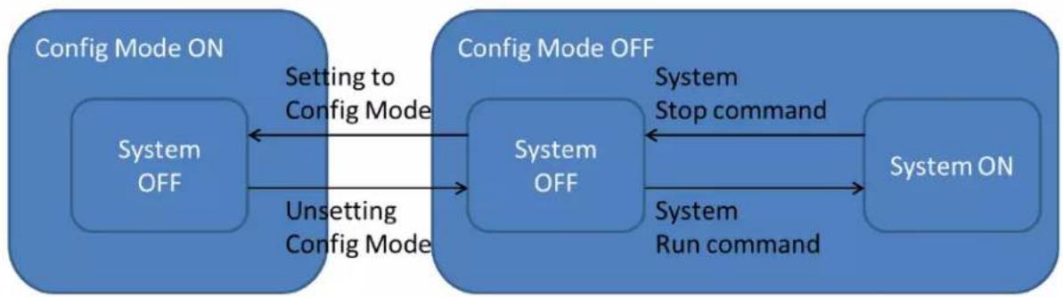
flowchart
graph LR
    A["Config Mode ON"] -->|Setting to Config Mode| B["System OFF"]
    B -->|Unsetting Config Mode| C["System OFF"]
    C -->|System Stop command| D["System ON"]
    D -->|System Run command| C
Figure 10 System Status Transition
Steps for putting iCM to "Config Mode" are described below.
1. Press the Home Button ☐ to show the "MainMenu" screen.
| MainMenu | 1/4 | |
| Status | ▶ | |
| Setting | ▶ | |
| ConfigMode | ▶ | |
| Password | ▶ | |
- On the "MainMenu" screen, turn the click-dial to select "ConfigMode" menu then press down on the click-dial to jump to "ConfigMode" screen.

| Status | |
| Setting | |
| ConfigMode | |
| Password |
- On the "ConfigMode" screen, turn the click-dial ⏻ to select "ConfigMode" menu then press down on the click-dial ⏻ to jump to input mode screen for "ConfigMode" menu.
| ConfigMode | 1/8 | |
| ConfigMode | OFF | |
| SystemSetting | ▶ | |
| DeviceRegistration | ▶ | |
| DeviceConfig | ▶ | |
- On the input mode screen for "ConfigMode" menu, turn the click-dial to select "ON" then press down on the click-dial to validate the command.
| ConfigMode | 1/1 | |
| ConfigMode | OFF | |
| ConfigMode | 1/1 | |
| ConfigMode | ON | |
8.3. System Configuration Setting
Various parameters related to iCM system such as language setting, unit settings can be done from system setting menu.
Menu structure and items which can be set are described below.
□MainMenu
○ ConfigMode
- SystemSetting
□ SystemSetting
○ Language......Switch between Japanese/English
Unit .... Switch between Metric / imperial unit system
- Date / Clock....Set date, time, and UTC time difference setting
○ Network ...... Set network related settings
- MainController......Set IP address, DHCP, G/W, subnet mask, and cloud
- BACneModule......Set IP address, DHCP, G/W, subnet mask, and device ID
- Cloud ....Set password
○ About .... About iCM
8.3.1. Setting Unit
Steps for changing current time / date settings are described below.
- Press the Home Button ☐ to show the "MainMenu" screen.
| MainMenu | 1/4 | |
| Status | ▶ | |
| Setting | ▶ | |
| ConfigMode | ▶ | |
| Password | ▶ | |
- On the "MainMenu" screen, turn the click-dial ⏻ to select "Setting" menu then press down on the click-dial ⏻ to jump to "Setting" screen.
| MainMenu | 2/4 | |
| Status | ▶ | |
| Setting | ▶ | |
| ConfigMode | ▶ | |
| Password | ▶ | |
- On the "Setting" screen, turn the click-dial to select "SystemSetting" menu then press down on the click-dial to jump to "System Setting" screen.
| Setting | 4/5 | |
| SystemCtrlParam | ▶ | |
| DeviceCtrlParam | ▶ | |
| CtrlModeSetting | ▶ | |
| SystemSetting | ▶ | |
- On the "System Setting" screen, turn the click-dial Ⓞ to select "Unit" menu, then press down on the click-dial Ⓥ to jump to input mode screen for "Unit" menu.
| SystemSetting | 2/5 | |
| Language | English | |
| Unit | Metric | |
| Date/Clock | ▶ | |
| Network | ▶ | |
- On the input mode screen for "Unit" menu, turn the click-dial to select "Metric" or "Imperial" then press down on the click-dial to validate the command.
| Unit | 1/1 | |
| Unit | Metric | |
| ConfigMode | 1/1 | |
| Unit | Imperial | |
8.3.2. Setting Current Time / Date
(Used screen: MainMenu → ConfigMode → Setting → System Setting → Date/Clock)
Steps for changing current time / date settings are described below.
- On the "Date/Clock" screen, turn the click-dial to select "Setting" menu then press down on the click-dial to jump to "Date/Clock Setting" screen.
| Date/Clock | 1/4 | |
| Setting | ▶ | |
| Date(M/D/Y) | 01/16/2015 | |
| Time(H:M:S) | 17:33:25 | |
| UTC_TimeDiff | -360min | |
- On the "Date/Clock Setting" screen, date and clock setting for the controller can be changed.
| Date/Clock Setting | 1/4 | |
| Date(M/D/Y) | 01/16/2015 | |
| Time(H:M:S) | 17:33:25 | |
| UTC_TimeDiff | -360min | |
| Reset | - | |
8.3.3. Changing Network Setting of Main Controller
(Used screen: MainMenu → ConfigMode → Setting → System Setting → Network)
Steps for changing network settings are described below.
- On the "Network" screen, current setting for network related setting of the Main controller can be checked.
| Network | 1/12 | |
| MainController | ||
| -Setting | ▶ | |
| -IP | 192.168.0.3 | |
| -Mask | 255.255.255.0 | |
| -G/W | 192.168.0.1 | |
| -DHCP | Passive | |
| BACnet_Module | ||
| -Status/Setting | ▶ | |
| Daikin On Site | ||
| -Status | ▶ | |
| HMIforWeb | ||
| -Status | ▶ | |
- On the "Network" screen turn the click-dial Ⓞ to select "Setting" menu under "MainController" then press down on the click-dial Ⓞ to jump to "MainController Network" screen.
| Network | 2/12 | |
| MainController | ||
| -Setting | ▶ | |
| -IP | 192.168.0.3 | |
| -Mask | 255.255.255.0 | |
| -G/W | 192.168.0.1 | |
| -DHCP | Passive | |
| BACnet_Module | ||
| -Status/Setting | ▶ | |
| Daikin On Site | ||
| -Status | ▶ | |
| HMIforWeb | ||
| -Status | ▶ | |
- On the "MainController Network" screen, network related setting for the main controller can be changed.
| Main Network | 1/8 | |
| Gvn IP | 192.168.0.9 | |
| Gvn Mask | 255.255.255.0 | |
| Gvn G/W | 192.168.0.13 | |
| DHCP | Passive | |
| PrimDNS | 000.000.000.000 | |
| SecDNS | 000.000.000.000 | |
| MAC | 00-00-00-00-00-00 | |
| Reset | - | |
- After setting is complete, it is required to reset the controller to reflect the setting. On the "MainController Network" screen, turn the click-dial 🔓 to select "Reset" menu then press down on the click-dial 🔓 to jump to input mode screen for "Reset"
| Main Network | 8/8 | |
| Gvn IP | 192.168.0.130 | |
| Gvn Mask | 255.255.255.0 | |
| Gvn G/W | 192.168.0.254 | |
| DHCP | Passive | |
| PrimDNS | 000.000.000.000 | |
| SecDNS | 000.000.000.000 | |
| MAC | 00-00-00-00-00-00 | |
| Reset | - | |
- On the input mode screen for "Reset", turn the click-dial to change value to "Reset" then press down on the click-dial to validate your setting. The controller will restart and your settings will be reflected.
Caution: By resetting the controller, the system will stop until the controller has finished restarting.
8.3.4. Changing Network Setting of BACnet Module
(Used screen: MainMenu → ConfigMode → Setting → System Setting → Network)
Steps for changing current BACnet settings are described below. Make sure the BACnet Module is connected correctly before changing the network setting.
- On the "Network" screen, current setting for network related setting of BACnet Module can be checked.
| Network | 1/12 | |
| MainController | ||
| -Setting | ▶ | |
| -IP | 192.168.0.3 | |
| -Mask | 255.255.255.0 | |
| -G/W | 192.168.0.1 | |
| -DHCP | Passive | |
| BACnet_Module | ||
| -Status/Setting | ▶ | |
| Daikin On Site | ||
| -Status | ▶ | |
| HMIforWeb | ||
| -Status | ▶ | |
- On the "Network" screen turn the click-dial ⏻ to select "Setting" menu under "BACnetModule" then press down on the click-dial ⏻ to jump to "BACnet NetworkSetting" screen.
| Network | 8/12 | |
| MainController | ||
| -Setting | ▶ | |
| -IP | 192.168.0.3 | |
| -Mask | 255.255.255.0 | |
| -G/W | 192.168.0.1 | |
| -DHCP | Passive | |
| BACnet_Module | ||
| -Status/Setting | ▶ | |
| DaikinOnSite | ||
| -Status | ▶ | |
| HMIforWeb | ||
| -Status | ▶ | |
- On the "BACnet NetworkSetting" screen, network related setting for the BACnet Module can be changed.
| BACnet IP Card | 1/19 | |
| State | Hardware | |
| Comm Failure | Active | |
| BACnet: | ||
| Device name | ||
| - | ||
| Device ID | 1 | |
| Port | 0 | |
| TCP/IP | ||
| DHCP | Passive | |
| Actual IP | 192.168.0.9 | |
| Actual Mask | 255.255.255.0 | |
| Act Gateway | 192.168.0.13 | |
| Given IP | 192.168.0.9 | |
| Given Mask | 255.255.255.0 | |
| Giv Gateway | 192.168.0.13 | |
| Write settings | Passive | |
| General | ||
| Software Version | ||
| Reset | - | |
Note: To overwrite the current settings “Write settings” must be turned into “Active”, before resetting the controller.
| BACnet IP Card | 19/19 | |
| Write settings | Active | |
| General | ||
| Software Version | ||
| Reset | ||
- After setting is complete, it is required to reset the controller to reflect the setting.
8.3.5. Changing Network Setting of Daikin On Site (DoS: Cloud Connection)
(Used screen: MainMenu → ConfigMode → Setting → System Setting → Network)
- On the "Network" screen turn the click-dial Ⓞ to select "DaikinOnSite" then press down on the click-dial Ⓞ to jump to input mode screen for "DaikinOnSite"
On the input mode screen for "DaikinOnSite", turn the click-dial Ⓞ to change value to "Enable" then press down on the click-dial ⏻ to validate your setting.
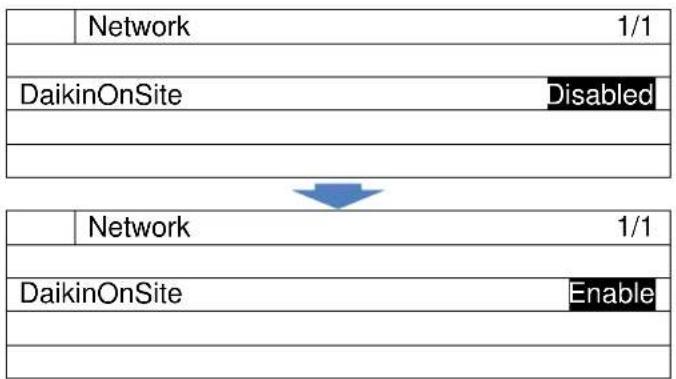
flowchart
graph TD
    A["Network 1/1"] --> B["DaikinOnSite Disabled"]
    B --> C["Network 1/1"]
    D["DaikinOnSite Enable"] --> E["End"]
- On the "Network" screen turn the click-dial Ⓞ to select "Status" menu under "Daikin On Site" then press down on the click-dial Ⓥ to jump to "Cloud Status" screen.
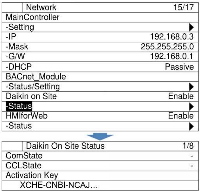
8.3.6. Showing information of iCM
(Used screen: MainMenu → ConfigMode → Setting → System Setting)
- On the "System Setting" screen, turn the click-dial to select "About" menu, then press down on the click-dial to jump to input mode screen for "About" menu.
| SystemSetting | 5/5 | |
| Unit | Metric | |
| Date/Clock | ▶ | |
| Network | ▶ | |
| About | ▶ | |
- The "About" menu displays versions of iCM and BSP.
| About | 1/3 | |
| iCM | - | |
| -Application | iCM | |
| -Date | dd/mm/yyyy | |
| -Version | 2.**.** | |
| iCM_Ver_2.**.** | ||
| HMI | - | |
| -Verson | ||
| iCMd_Ver2.**.** | ||
| -GUID | ||
| 4518B7BC-69D9-43A9-ABF0-945... | ||
| Controller | ||
| -BSP | 10.36 | |
| -SerialNr | 9554 | |
8.4. Equipment Registration
Number and types of equipment which are controlled from iCM can be set from equipment registration menu.
Menu structure and items which can be set are described below.
□MainMenu
○ ConfigMode
■ DeviceRegistration
□ DeviceRegistration
○ Chiller ......Register available chillers
○ PrimaryPump ...... Register available primary pumps
- CondenserPump ...... Register available condenser pumps
- CTBypassValve ....Register available CT bypass valves
- Sensors ...... Register available sensors
- ExtI/O...... Register available ext. modules
○ BACnet_Module......Register availability of BACnet module
- Press the Home Button ☐ to show the "MainMenu" screen.
| MainMenu | 1/4 | |
| Status | ▶ | |
| Setting | ▶ | |
| ConfigMode | ▶ | |
| Password | ▶ | |
- On the "MainMenu" screen, turn the click-dial to select "ConfigMode" menu then press down on the click-dial to jump to "ConfigMode" screen.
| MainMenu | 3/4 | |
| Status | ▶ | |
| Setting | ▶ | |
| ConfigMode | ▶ | |
| Password | ▶ | |
- On the "Setting" screen, turn the click-dial to select "DeviceRegistration" menu then press down on the click-dial to jump to "DeviceRegistration" screen.
| ConfigMode | 3/8 | |
| ConfigMode | ▶ | |
| SystemSetting | ▶ | |
| DeviceRegistration | ▶ | |
| DeviceConfig | ▶ | |
- "DeviceRegistration" screen is shown. From this screen, you can register different equipment
| DeviceRegistration | 1/14 | |
| Chiller | ▶ | |
| PrimaryPump | ▶ | |
| CondenserPump | ▶ | |
| CTBypassValve | ▶ | |
| Sensors | ▶ | |
| ExtI/O | ▶ | |
| BACnet_Module | IgnoreCommError | |
| Reset | - | |
← 8.4.1 Chiller Registration
← 8.4.2 PrimaryPump Registration
← 8.4.3 CondenserPump Registration
← 8.4.4 CTBypassValve Registration
← 8.4.5 Sensors Registration
← 8.4.6 ExtI/O Registration
← 8.4.7 BACnet_Module Registration
NOTE: After registration of all equipment is complete, it is required to reset the controller to reflect the chenages before keeping on configuration.
- On the input mode screen for "Reset", turn the click-dial to change value to "Reset" then press down on the click-dial to validate your setting. The controller will restart and your settings will be reflected.
Caution: By resetting the controller, the system will stop until the controller has finished restarting.
8.4.1. Chiller Registration
(Used screen: MainMenu > ConfigMode > DeviceRegistration > Chiller Registration)
- From "DeviceRegistration" screen, turn the click-dial to select "Chiller" menu then press down on the click-dial to jump to "Chiller Registration" screen.
| DeviceRegistration | 1/9 | |
| Chiller | ▶ | |
| PrimaryPump | ▶ | |
| CondenserPump | ▶ | |
| CTBypassValve | ▶ | |
- "Chiller Registration" screen is displayed. Here, maximum of 8 chillers with respective evaporator and condenser side shut-off valves can be registered by setting the value to "Enable".
| Chiller Registration | 1/25 | |
| -#01 | Enable | |
| -EvShutOffValve | Disable | |
| -CndShutOffValve | Disable | |
| -#02 | Disable | |
| -EvShutOffValve | Disable | |
| -CndShutOffValve | Disable | |
| -#03 | Disable | |
| -EvShutOffValve | Disable | |
| -CndShutOffValve | Disable | |
| -#04 | Disable | |
| -EvShutOffValve | Disable | |
| -CndShutOffValve | Disable | |
| -#05 | Disable | |
| -EvShutOffValve | Disable | |
| -CndShutOffValve | Disable | |
| -#06 | Disable | |
| -EvShutOffValve | Disable | |
| -CndShutOffValve | Disable | |
| -#07 | Disable | |
| -EvShutOffValve | Disable | |
| -CndShutOffValve | Disable | |
| -#08 | Disable | |
| -EvShutOffValve | Disable | |
| -CndShutOffValve | Disable | |
| Reset | - | |
NOTE: In case of registration of air-cooled chiller CndShutOffValve must be set "Disable"
8.4.2. PrimaryPump Registration
(Used screen: MainMenu → ConfigMode → DeviceRegistration → PrimaryPump Registration)
NOTE: At least one primary pump (as dummy pump) must be registered, even if iCM does not have any management.
- From "DeviceRegistration" screen, turn the click-dial ⏻ to select "PrimaryPump" menu then press down on the click-dial ⏻ to jump to "PriPump Registration" screen.
| DeviceRegistration | 2/9 | |
| Chiller | ▶ | |
| PrimaryPump | ▶ | |
| CondenserPump | ▶ | |
| CTBypassValve | ▶ | |
- "PriPump Registration" screen is displayed. Here, maximum of 8 primary pumps can be registered by setting the value to "Enable".
| PriPump Registration | 1/9 | |
| -#01 | Enable | |
| -#02 | Disable | |
| -#03 | Disable | |
| -#04 | Disable | |
| -#05 | Disable | |
| -#06 | Disable | |
| -#07 | Disable | |
| -#08 | Disable | |
| Reset | - | |
8.4.3. CondenserPump Registration
(Used screen: MainMenu → ConfigMode → DeviceRegistration → CondenserPump)
NOTE: This menu displays on HMI, but hardware of models EKDICMPA* does not support this function.
NOTE: At least one condenser pump (as dummy pump) must be registered, even in case of air-cooled chiller plant room
- From "DeviceRegistration" screen, turn the click-dial Ⓞ to select "CondenserPump" menu then press down on the click-dial Ⓞ to jump to "CondenserPump Registration" screen.
| DeviceRegistration | 3/9 | |
| Chiller | ▶ | |
| PrimaryPump | ▶ | |
| CondenserPump | ▶ | |
| CTBypassValve | ▶ | |
- "CondenserPump Registration" screen is displayed. Here, maximum of 8 condenser pumps can be registered by setting the value to "Enable".
| CondenserPump Registration | 1/9 | |
| -#01 | Enable | |
| -#02 | Disable | |
| -#03 | Disable | |
| -#04 | Disable | |
| -#05 | Disable | |
| -#06 | Disable | |
| -#07 | Disable | |
| -#08 | Disable | |
| Reset | - | |
8.4.4. CTBypassValve Registration
(Used screen: MainMenu → ConfigMode → DeviceRegistration → CTBypassValve)
NOTE: This menu displays on HMI, but hardware of models EKDICMPA* does not support this function.
- From "DeviceRegistration" screen, turn the click-dial ⏻ to select "CTBypassValve" menu then press down on the click-dial ⏻ to jump to "CTBypassValve Registration" screen.
| DeviceRegistration | 4/9 | |
| Chiller | ▶ | |
| PrimaryPump | ▶ | |
| CondenserPump | ▶ | |
| CTBypassValve | ▶ | |
- "CTBypassValve Registration" screen is displayed. Here, maximum of 4 cooling tower bypass valves can be registered by setting the value to "Enable".
| CTBypassValve Registration | 1/5 | |
| -#01 | Enable | |
| -#02 | Disable | |
| -#03 | Disable | |
| -#04 | Disable | |
| Reset | - | |
8.4.5. Sensors Registration
(Used screen: MainMenu → ConfigMode → DeviceRegistration)
- From "DeviceRegistration" screen, turn the click-dial Ⓞ to select "Sensors" menu then press down on the click-dial Ⓥ to jump to "Sensors Registration" screen.
| DeviceRegistration | 5/9 | |
| CTBypassValve | ▶ | |
| Sensors | ▶ | |
| ExtI/O | ▶ | |
| -Reset | ||
- "Sensors Registration" screen is displayed. Here, sensors for each of the condenser piping groups (up to four) can be registered by setting the value to "Enable".
| Sensors Registration | 1/18 | |
| OutdoorTemp | Enable | |
| CndPipingGroup1 | ||
| -CndWtLvgTemp | Disable | |
| -CndWtEntTemp | Disable | |
| -CndDiffPress | Enable | |
| CndPipingGroup2 | ||
| -CndWtLvgTemp | Disable | |
| -CndWtEntTemp | Disable | |
| -CndDiffPress | Disable | |
| CndPipingGroup3 | ||
| -CndWtLvgTemp | Disable | |
| -CndWtEntTemp | Disable | |
| -CndDiffPress | Disable | |
| CndPipingGroup4 | ||
| -CndWtLvgTemp | Disable | |
| -CndWtEntTemp | Disable | |
| -CndDiffPress | Disable | |
| Reset | Reset | |
NOTE: This menu displays on HMI, but hardware of models EKDICMPA* does not support this function.
8.4.6. ExtI/O Registration
(Used screen: MainMenu → ConfigMode → DeviceRegistration)
- From "DeviceRegistration" screen, turn the click-dial to select "ExtI/O" menu then press down on the click-dial to jump to "ExtI/O Registration" screen.
| DeviceRegistration | 6/9 | |
| CTBypassValve | ▶ | |
| Sensors | ▶ | |
| ExtI/O | ▶ | |
| -Reset | ||
- From "ExtI/O Registration" screen, availability of 8 ExtI/O modules can be set. If ExtI/O is set as available but connection is not found, iCM will be in alarm status.
| ExtI/O Registration | 1/18 | |
| -#01 | Disable | |
| -#02 | Disable | |
| -#03 | Disable | |
| -#04 | Disable | |
| -#05 | Disable | |
| -#06 | Disable | |
| -#09 | Disable | |
| -#10 | Disable | |
| -#11 | Disable | |
| -#12 | Disable | |
| -#13 | Disable | |
| -#14 | Disable | |
| -#15 | Disable | |
| -#16 | Disable | |
| -Reset | - | |
← Availability of ExtIO #1
← Availability of ExtIO #2
← Availability of ExtIO #3
← Availability of ExtIO #4
← Availability of ExtIO #5
← Availability of ExtIO #6
← Availability of ExtIO #9
← Availability of ExtIO #10
← Availability of ExtIO #11
← Availability of ExtIO #12
← Availability of ExtIO #13
← Availability of ExtIO #14
← Availability of ExtIO #15
← Availability of ExtIO #16
8.4.7. BACnet\_Module Registration
(Used screen: MainMenu → ConfigMode → DeviceRegistration)
- From "DeviceRegistration" screen, availability of BACnet module can be set. If BACnet is set as available but connection is not found, iCM will be in alarm status.
| DeviceRegistration | 8/9 | |
| PrimaryPump | ▶ | |
| ExtI/O | ▶ | |
| -Reset | ||
| BACnet_Module | IgnoreCommError | |
← Availability of BACnet Module
8.5. Equipment Configuration
Initial setting of attributes for each equipment can be done from this menu. Menu structure and items which can be set are described below.
□MainMenu
○ Config
■ DeviceConfig
□ DeviceConfig
- System .... Set temperature setpoint
○ Chiller ....Set chiller type, capacity, run hours - EvShutOffValve .... Set whether feedback signal is available
○ CndShutOffValve ....Set availability for condenser pump shutoff valves
o PrimaryPump....Set run hours, whether feedback signal is available - CondenserPump....Set piping groups for condenser pumps
-
Sensor .... Set input type for sensor
○ ModbusCommSetting ...... Set Modbus BaudRate, Parity, Stop Bits, and Time out
○ AiThreshold...... Set threshold for judging open loop of Ai signal -
Press the Home Button ☐ to show the "MainMenu" screen.
| MainMenu | 1/4 | |
| Status | ▶ | |
| Setting | ▶ | |
| ConfigMode | ▶ | |
| Password | ▶ | |
- On the "MainMenu" screen, turn the click-dial to select "ConfigMode" menu then press down on the click-dial to jump to "ConfigMode" screen.
| MainMenu | 3/4 | |
| Status | ▶ | |
| Setting | ▶ | |
| ConfigMode | ▶ | |
| Password | ▶ | |
- On the "Setting" screen, turn the click-dial to select "DeviceConfig" menu then press down on the click-dial to jump to "DeviceConfig" screen.
| ConfigMode | 3/4 | |
| ConfigMode | ▶ | |
| SystemSetting | ▶ | |
| DeviceRegistration | ▶ | |
| DeviceConfig | ▶ | |
- "DeviceConfig" screen is shown. From this screen, you can do initial setting of equipment.
| DeviceConfig | 1/12 | |
| System | ▶ | |
| Chiller | ▶ | |
| EvShutOffValve | ||
| -StatusSignal | Avail | |
| CndShutOffValve | ||
| -StatusSignal | Avail | |
| PrimaryPump | ▶ | |
| CondenserPump | ▶ | |
| Sensor | ▶ | |
| ModbusCommSetting | ▶ | |
| AiThreshold | ||
| -mA | 1.0mA | |
← 8.5.1 System Configuration
← 8.5.2 Chiller Configuration
← 8.5.3 Evaporator Shut Off Valve Configuration
← 8.5.4 Condenser Shut Off Valve
← 8.5.5 Primary Pump
← 8.5.6 Condenser Pump
← 8.5.7 Sensor
← 8.5.8 Modbus Communication Setting
← 8.5.9 Ai Threshold Setting
NOTE: After configuration of all equipment is complete, it is required to reset the controller to reflect the chenages before keeping on setting.
- On the input mode screen for "Reset", turn the click-dial to change value to "Reset" then press down on the click-dial to validate your setting. The controller will restart and your settings will be reflected.
8.5.1. System Configuration
(Used screen: MainMenu → ConfigMode → DeviceConfig → System Config)
- From "DeviceConfig" screen, turn the click-dial Ⓞ to select "System" menu then press down on the click-dial Ⓥ to jump to "System" screen.
| DeviceConfig | 1/12 | |
| System | ▶ | |
| Chiller | ▶ | |
| EvShutOffValve | ||
| -StatusSignal | Avail | |
- "System Config" screen is displayed. Here, you can configure attributes of chillers.
| System Config | 1/3 | |
| TempSetPt | ||
| -MaxOutput | 48.9°C | ← a. |
| -MinOutput | 12.2°C | ← b. |
Table 16 List of parameters which can be set from "Chiller Config" screen
| ID | Name | Definition |
| a. | -MaxOutput | Maximum temperature setpoint of system |
| b. | -MinOutput | Minimum temperature setpoint of system |
8.5.2. Chiller Configuration
(Used screen: MainMenu → ConfigMode → DeviceConfig → Chiller Config)
- From "DeviceConfig" screen, turn the click-dial to select "Chiller" menu then press down on the click-dial to jump to "Chiller" screen.
| DeviceConfig | 2/12 | |
| System | ▶ | |
| Chiller | ▶ | |
| EvShutOffValve | ||
| -StatusSignal | Avail | |
- "Chiller Config" screen is displayed. Here, you can configure attributes of chillers.
| Chiller Config | 1/65 | |
| Status Signal | Avail | |
| #01 | ||
| -ChillerType | MQ_GB | |
| -CoolingMaxCap | 100kW | |
| -Runhours | 10h | |
| -PipingGroup | 1 | |
| -MinPumpReq | 1 | |
| -CndPipingGroup | 1 | |
| -CndMinPumpReq | 1 |
| #02 | |
| -ChillerType | MQ_GB |
| -CoolingMaxCap | 100kW |
| -Runhours | 10h |
| -PipingGroup | 1 |
| -MinPumpReq | 1 |
| -CndPipingGroup | 1 |
| -CndMinPumpReq | 1 |
| #03 | |
| -ChillerType | MQ_GB |
| -CoolingMaxCap | 100kW |
| -Runhours | 10h |
| -PipingGroup | 1 |
| -MinPumpReq | 1 |
| -CndPipingGroup | 1 |
| -CndMinPumpReq | 1 |
| #04 | |
| -ChillerType | MQ_GB |
| -CoolingMaxCap | 100kW |
| -Runhours | 10h |
| -PipingGroup | 1 |
| -MinPumpReq | 1 |
| -CndPipingGroup | 1 |
| -CndMinPumpReq | 1 |
| #05 | |
| -ChillerType | MQ_GB |
| -CoolingMaxCap | 100kW |
| -Runhours | 10h |
| -PipingGroup | 1 |
| -MinPumpReq | 1 |
| -CndPipingGroup | 1 |
| -CndMinPumpReq | 1 |
| #06 | |
| -ChillerType | MQ_GB |
| -CoolingMaxCap | 100kW |
| -Runhours | 10h |
| -PipingGroup | 1 |
| -MinPumpReq | 1 |
| -CndPipingGroup | 1 |
| -CndMinPumpReq | 1 |
| #07 | |
| -ChillerType | MQ_GB |
| -CoolingMaxCap | 100kW |
| -Runhours | 10h |
| -PipingGroup | 1 |
| -MinPumpReq | 1 |
| -CndPipingGroup | 1 |
← h.
| -CndMinPumpReq | 1 |
| #08 | |
| -ChillerType | MQ_GB |
| -CoolingMaxCap | 100kW |
| -Runhours | 10h |
| -PipingGroup | 1 |
| -MinPumpReq | 1 |
| -CndPipingGroup | 1 |
| -CndMinPumpReq | 1 |
Table 17 List of parameters which can be set from "Chiller Config" screen
| ID | Name | Definition |
| a. | StatusSignal | Availability of feedback signal for chiller ON/OFF status |
| b. | -ChillerType | Chiller type to decide type of communication protocol |
| c. | -CoolingMaxCap | Maximum capacity (100% actual capacity) value of chiller |
| d. | -Runhours | Total run hours of chiller as initial value |
| e. | PipingGroup | Piping group of chiller to be associated with pumps |
| f. | MinPumpReq | Minimum number of pumps required from chiller |
| g. | CndPipingGroup | Piping group of chiller to be associated with condenser pumps |
| h. | CndMinPumpReq | Minimum number of condenser pumps required from chiller |
NOTE: in case no primary pumps or condenser pumps are connected and managed by iCM, user have to set:
- MinPumpReq = 0
- CndMinPumpReq = 0
8.5.3. Evaporator Shut Off Valve Configuration
(Used screen: MainMenu → ConfigMode → DeviceConfig)
- From "DeviceConfig" screen, you can configure availability of feedback signal for valve Open/Close status.
| DeviceConfig | 4/12 | |
| Chiller | ▶ | |
| EvShutOffValve | ||
| -StatusSignal | Avail | |
| CndShutOffValve | ||
8.5.4. Condenser Shut Off Valve Configuration
(Used screen: MainMenu → ConfigMode → DeviceConfig)
NOTE: This menu displays, but hardware of models EKDICMPA* does not support this function.
- From "DeviceConfig" screen, you can configure availability of feedback signal for valve Open/Close status.
| DeviceConfig | 6/12 | |
| EvShutOffValve | ||
| -StatusSignal | Avail | |
| CndShutOffValve | ||
| -StatusSignal | Avail | |
NOTE: with models EKDICMPA* "StatusSignal" must be set as "Not Avail".
8.5.5. Primary Pump Configuration
(Used screen: MainMenu → ConfigMode → DeviceConfig → PrimaryPump Config)
- From "DeviceConfig" screen, turn the click-dial to select "PrimaryPump" menu then press down on the click-dial to jump to "PrimaryPump" screen.
| DeviceConfig | 7/12 | |
| PrimaryPump | ▶ | |
| CondenserPump | ▶ | |
| Sensor | ▶ | |
| ModbusCommSetting | ▶ | |
- "PrimaryPump Config" screen is displayed. Here, you can configure attributes of primary pumps.
| PrimaryPump Config | 1/25 | |
| StatusSignal | Avail | |
| #01 | ||
| -Runhours | 10h | |
| -PipingGroup | 1 | |
| #02 | ||
| -Runhours | 10h | |
| -PipingGroup | 1 | |
| #03 | ||
| -Runhours | 10h | |
| -PipingGroup | 1 | |
| #04 | ||
| -Runhours | 10h | |
| -PipingGroup | 1 | |
| #05 | ||
| -Runhours | 10h | |
| -PipingGroup | 1 | |
| #06 | ||
| -Runhours | 10h | |
| -PipingGroup | 1 | |
| #07 | ||
| -Runhours | 10h | |
| -PipingGroup | 1 | |
| #08 | ||
| -Runhours | 10h |
| -PipingGroup | 1 |
Table 18 List of parameters which can be set from "PrimaryPump Config" screen
| ID | Name | Definition |
| a. | StatusSignal | Availability of feedback signal for pump ON/OFF status |
| b. | -Runhours | Total run hours of pump as initial value |
| c. | -PipingGroup | Piping group the pump belongs to |
8.5.6. Condenser Pump Configuration
(Used screen: MainMenu → ConfigMode → DeviceConfig → CondenserPump Config)
NOTE: This menu displays, but hardware of models EKDICMPA\* does not support this function.
- From "DeviceConfig" screen, turn the click-dial to select "CondenserPump" menu then press down on the click-dial to jump to "CondenserPump" screen.
| DeviceConfig | 7/12 | |
| PrimaryPump | ▶ | |
| CondenserPump | ▶ | |
| Sensor | ▶ | |
| ModbusCommSetting | ▶ | |
- "CondenserPump Config" screen is displayed. Here, you can configure attributes of condenser pumps.
| CondenserPump Config | 1/25 | |
| StatusSignal | Avail | |
| #01 | ||
| -Runhours | 10h | |
| -PipingGroup | 1 | |
| #02 | ||
| -Runhours | 10h | |
| -PipingGroup | 1 | |
| #03 | ||
| -Runhours | 10h | |
| -PipingGroup | 1 | |
| #04 | ||
| -Runhours | 10h | |
| -PipingGroup | 1 | |
| #05 | ||
| -Runhours | 10h | |
| -PipingGroup | 1 | |
| #06 | ||
| -Runhours | 10h | |
| -PipingGroup | 1 | |
| #07 | |
| -Runhours | 10h |
| -PipingGroup | 1 |
| #08 | |
| -Runhours | 10h |
| -PipingGroup | 1 |
NOTE: with models EKDICMPA* "StatusSignal" must be set as "Not Avail".
Table 19 List of parameters which can be set from "CondenserPump Config" screen
| ID | Name | Definition |
| a. | StatusSignal | Availability of feedback signal for pump ON/OFF status |
| b. | -Runhours | Total run hours of pump as initial value |
| c. | -PipingGroup | Piping group the pump belongs to |
8.5.7. Sensor Configuration
(Used screen: MainMenu → ConfigMode → DeviceConfig → SensorConfig)
- From "DeviceConfig" screen, turn the click-dial Ⓞ to select "Sensor" menu then press down on the click-dial Ⓥ to jump to "SensorConfig" screen.
| Device Config | 9/12 | |
| PrimaryPump | ▶ | |
| CondenserPump | ▶ | |
| Sensor | ▶ | |
| ModbusCommSetting | ▶ | |
- "SensorsConfig" menu is displayed. Here you can set attributes of sensors. Note: sensor type for differential pressure sensor is fixed to mA type.
| SensorsConfig | 1/12 | |
| ChWtLvgTemp | ||
| -PortType | mA | ← a. |
| ChWtEntTemp | ||
| -Porttype | mA | ← b. |
| CndWtLvgTemp | ||
| -PortType | mA | ← c. |
| CndWtEntTemp | ||
| -Porttype | mA | ← d. |
| OATemp | ||
| -PortType | mA | ← e. |
| SensorConversionParam | ► | ← 8.5.7.1 Setting sensor conversion parameter when using mA type |
| NTCSensorConversionParam | ► | ← 8.5.7.2 Setting sensor conversion parameter when using NTC10K type |
| ID | Name | Definition |
| a. | -PortType | PortType for Chilled Water Leaving Temperature sensor (mA / NTC10K) |
| b. | -PortType | PortType for Chilled Water Entering Temperature sensor (mA / NTC10K) |
| c. | -PortType | PortType for Condensed Water Leaving Temperature sensor (mA / NTC10K) |
| d. | -PortType | PortType for Condensed Water Entering Temperature sensor (mA / NTC10K) |
| e. | -PortType | PortType for Outdoor Air Temperature sensor (mA/NTC10K) |
Table 20 List of parameters which can be set from "SensorsConfig" screen
NOTE: Chilled Water temperature sensor are NTC10K sensors and are supplied with panel.
NOTE: Condenser Water Temperature sensors setting display, but hardware of models EKDICMPA* does not support this equipment
8.5.7.1. Setting sensor conversion parameter when using mA type
Image of sensor conversion when using mA type is shown on Figure 11.
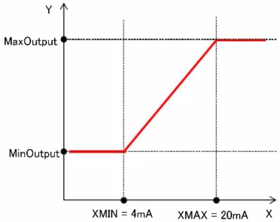
line
| X | Y | |------------|-------| | 0 | MaxOutput | | 4mA | MinOutput | | 20mA | MaxOutput |Figure 11 Sensor value conversion of 4-20mA
- From "MainMenu > ConfigMode > SensorsConfig" screen, turn the click-dial Ⓞ to select "SensorConversionParam" menu then press down on the click-dial Ⓞ to jump to "SensorConvParam" screen.
| SensorsConfig | 11/12 | |
| OATemp | ||
| -Porttype | mA | |
| SensorConversionParam | ▶ | |
| NTCSensorConversionPara m | ▶ | |
- "SensorConvParam" screen is shown. Here, parameters for conversion of mA sensor input can be done
| SensorConvParam | 1/21 | |
| ChWtLvgTemp | ||
| -MaxOutput | 75.0°C | a. |
| -MinOutput | -25.0°C | b. |
| ChWtEntTemp | ||
| -MaxOutput | 75.0°C | c. |
| -MinOutput | -25.0°C | d. |
| DiffPress | ||
| -MaxOutput | 683kPa | e. |
| -MinOutput | 0kPa | f. |
| CndWtLvgTemp | ||
| -MaxOutput | 75.0°C | g. |
| -MinOutput | -25.0°C | h. |
| CndWtEntTemp | ||
| -MaxOutput | 75.0°C | i. |
| -MinOutput | -25.0°C | j. |
| CndDiffPress | ||
| -MaxOutput | 683kPa | k. |
| -MinOutput | 0kPa | l. |
| OATemp | ||
| -MaxOutput | 75.0°C | m. |
| -MinOutput | -25.0°C | n. |
Table 21 List of parameters which can be set from "SensorConvParam" screen
| ID | Name | Definition |
| a. | -MaxOutput | Linear output value of chilled water leaving temperature corresponding to 20mA input |
| b. | -MinOutput | Linear output value of chilled water leaving temperature corresponding to 4mA input |
| c. | -MaxOutput | Linear output value of chilled water entering temperature corresponding to 20mA input |
| d. | -MinOutput | Linear output value of chilled water entering temperature corresponding to 4mA input |
| e. | -MaxOutput | Linear output value of differential pressure corresponding to 20mA input |
| f. | -MinOutput | Linear output value of differential pressure corresponding to 4mA input |
| g. | -MaxOutput | Linear output value of condensed water leaving temperature corresponding to 20mA input |
| h. | -MinOutput | Linear output value of condensed water leaving temperature corresponding to 4mA input |
| i. | -MaxOutput | Linear output value of condensed water entering temperature corresponding to 20mA input |
| j. | -MinOutput | Linear output value of condensed water entering temperature corresponding to 4mA input |
| k. | -MaxOutput | Linear output value of condenser differential pressure corresponding to 20mA input |
| l. | -MinOutput | Linear output value of condenser differential pressure corresponding to 4mA input |
| m. | -MaxOutput | Linear output value of outdoor air temperature corresponding to 20mA input |
| n. | -MinOutput | Linear output value of outdoor air temperature corresponding to 4mA input |
8.5.7.2. Setting sensor conversion parameter when using NTC10K type
Image of sensor conversion when using mA type is shown on Figure 11.
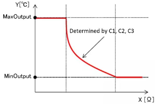
line
| X [Ω] | Y [°C] | |-------|--------| | 0 | MaxOutput | | 500 | MinOutput | | >500 | Determined by C1, C2, C3 |Figure 12 Sensor value conversion of NTC10K
The non-linear part of conversion is modelled by Steinhart-Hart equation as described below. Parameters C1, C2, C3 are required to be set to determine the shape of the equation.
$$ T e m p e r a t u r e o u t p u t = \frac {1}{C _ {1} \times 1 0 ^ {- 4} + C _ {2} \times 1 0 ^ {- 4} \times \ln (x) + C _ {3} \times 1 0 ^ {- 8} \times \ln {(x)} ^ {3} - 2 7 3 . 1 5} $$
Equation 1 Steinhart-Hart Equation
- From "MainMenu > ConfigMode > SensorsConfig" screen, turn the click-dial to select "NTCSensorConversionParam" menu then press down on the click-dial to jump to "NTCSensorConvParam" screen.
| SensorsConfig | 6/6 | |
| OATemp | ||
| -Porttype | mA | |
| SensorConversionParam | ▶ | |
| NTCSensorConversionPara m | ▶ | |
- "SensorConvParam" screen is shown. Parameters for conversion of NTC sensor input can be done.
| NTCSensorConvParam | 1/30 |
| ChWtLvgTemp | |
| -C1 E-4 | 11.3510 |
| -C2 E-4 | 2.3296 |
| -C3 E-8 | 9.3665 |
| -MaxOutput | 75.0°C |
| -MinOutput | -25.0°C |
| ChWtEntTemp | |
| -C1 E-4 | 11.3510 |
| -C2 E-4 | 2.3296 |
| -C3 E-8 | 9.3665 |
| -MaxOutput | 75.0°C |
| -MinOutput | -25.0°C |
| CndWtLvgTemp | |
| -C1 E-4 | 11.3510 |
| -C2 E-4 | 2.3296 |
| -C3 E-8 | 9.3665 |
| -MaxOutput | 75.0°C |
| -MinOutput | -25.0°C |
| CndWtEntTemp | |
| -C1 E-4 | 11.3510 |
| -C2 E-4 | 2.3296 |
| -C3 E-8 | 9.3665 |
| -MaxOutput | 75.0°C |
| -MinOutput | -25.0°C |
| OATEmp | |
| -C1 E-4 | 11.3510 |
| -C2 E-4 | 2.3296 |
| -C3 E-8 | 9.3665 |
| -MaxOutput | 75.0°C |
| -MinOutput | -25.0°C |
Table 22 List of parameters which can be set from "NTCSensorConvParam" screen
| ID | Name | Definition |
| a. | -C1 E-4 | Steinhart-Hart coefficient |
| b. | -C2 E-4 | Steinhart-Hart coefficient (In(X) term) |
| c. | -C3 E-8 | Steinhart-Hart coefficient (In(X) ^3 term ) |
| d. | -MaxOutput | Maximum output value |
| e. | -MinOutput | Minimum output value |
NOTE: The default values refer to NTCK10 sensor supplied with panel.
8.5.8. Modbus Communication Setting
(Used screen: MainMenu → ConfigMode → DeviceConfig → ModbusCommSetting)
- From "DeviceConfig" screen, turn the click-dial to select "ModbusCommSetting" menu then press down on the click-dial to jump to "ModbusCommSetting" screen.
| DeviceConfig | 10/12 | |
| PrimaryPump | ▶ | |
| CondenserPump | ▶ | |
| Sensor | ▶ | |
| ModbusCommSetting | ▶ | |
- "ModbusCommSetting" screen is displayed. Here, you can configure Modbus communication between iCM and chiller.
| ModbusCommSetting | 1/4 | |
| BaudRate | 19200bps | |
| Parity | None | |
| StopBits | 1bit | |
| ResponseTimeout | 1000ms | |
← a.
← b.
← C.
← d.
Table 23 List of parameters which can be set from "ModbusCommSetting" screen
| ID | Name | Definition |
| a. | BaudRate | Baud rate setting of RS485 |
| b. | Parity | Parity bit setting of RS485 |
| c. | StopBits | Stop bit setting of RS485 |
| d. | ResponseTimeout | Wait time for response on each command before time out |
NOTE: Modbus communication parameter must match with Communication setting on chiller controller
8.5.9. Ai Threshold Setting
(Used screen: MainMenu → ConfigMode → DeviceConfig)
You can set threshold for judging open loop of Ai signal. The setting is common for all Ai signal. If open loop is detected, iCM will be in alarm status.
| DeviceConfig | 12/12 | |
| Sensor | ||
| ModbusCommSetting | ||
| AiThreshold | ||
| -mA | 1.0mA ← a. | |
Table 24 List of parameters which can be set from "DeviceConfig" screen
| ID | Name | Definition |
| a. | -mA | Threshold for detecting open loop. If Input is less that this value, it is considered open loop. |
NOTE: If users want to disable open loop detection for Ai signal, set "0.0mA" to this parameter.
9. Equipment Control Setting
Setting of various control parameters for each equipment can be done from this menu. Menu structure and items which can be set are described below.
□MainMenu
○ Setting
- DeviceCtrlParam
□ DevcieCtrlParam
○ Chiller ....Set sequencing type, staging type, min/max operating chillers
etc
o PrimaryPump....Set PI parameters, setpoint etc for pump VFD control
○ BypassValve....Set PI parameters, setpoint etc for bypass valve control
○ CondenserPump....Set PI parameters, setpoint etc for pump VFD control
- CTBypassValve ....Set PI parameters, setpoint etc for bypass valve control
- Press the Home Button ☐ to show the "MainMenu" screen.
| MainMenu | 1/4 | |
| Status | ▶ | |
| Setting | ▶ | |
| ConfigMode | ▶ | |
| Password | ▶ | |
- On the "MainMenu" screen, turn the click-dial to select "Setting" menu then press down on the click-dial to jump to "Setting" screen.
| MainMenu | 2/4 | |
| Status | ▶ | |
| Setting | ▶ | |
| ConfigMode | ▶ | |
| Password | ▶ | |
- On the "Setting" screen, turn the click-dial to select "DeviceCtrlParam" menu then press down on the click-dial to jump to "DeviceCtrlParam" screen.
| Setting | 2/5 | |
| SystemCtrlParam | ▶ | |
| DeviceCtrlParam | ▶ | |
| CtrlModeSetting | ▶ | |
| SystemSetting | ▶ | |
- DeviceCtrlParam screen is shown. From this screen, you can jump to control parameter setting for different equipment.
| DeviceCtrlParam | 1/5 | |
| Chiller | ▶ | |
| PrimaryPump | ▶ | |
| BypassValve | ▶ | |
| CondenserPump | ▶ | |
| CTBypassValve | ▶ | |
← 9.1 Chiller Control Setting
← 9.2 Primary Pump Control Setting
← 9.3 Bypass Valve Control Setting
← 9.4 Condenser Pump Control Setting
← 9.5 Cooling Tower Bypass Valve Control Setting
9.1. Chiller Control Setting
(Used screen: MainMenu > Setting > DeviceCtrlParam > ChillerCtrlParam)
- From "MainMenu > Setting > DeviceCtrlParam" screen, turn the click-dial 🔒 to select "Chiller" menu then press down on the click-dial 🔒 to jump to "ChillerCtrlParam" screen.
| DeviceCtrlParam | 1/5 | |
| Chiller | ▶ | |
| PrimaryPump | ▶ | |
| BypassValve | ▶ | |
| CondenserPump | ▶ | |
- "ChillerCtrlParam" screen is displayed. Here, various options for chiller control can be set.
| Chiller Ctrl | 1/20 | |
| Sequencing | ||
| -Type | FixedOrder | |
| -Order | ▶ | |
| -PonyChCtl | Disable | |
| -PonyChNo | 1 | |
| -StgDnWaitTime | 5min | |
| Staging | ||
| -Type | Temp | |
| -StgByTargetLoad | Disable | |
| -StgForRotation | Disable | |
| -WaitTime | 24h | |
| -MinRunningCh | 1 | |
| -MaxRunningCh | 1 | |
| -Detail | ▶ | |
| StabilizeTime | ||
| -up-up | 5min | |
| -dn-up | 10min | |
| -dn-dn | 3min | |
| -up-dn | 10min | |
| TempDiff(SoftLoad) | 1.0°C | |
Table 25 shows the list of parameters which can be set from "ChillerCtrl" screen
Table 25 List of parameters which can be set from "Chiller Ctrl" screen
| ID | Name | Range | Definition |
| a. | -Type | FixedOrder TimeOrder | Type of chiller sequencing (Fixed order / operation hours based) |
| b. | -PonyChCtl | Enable Disable | Enable / disable pony chiller (Pony chiller is a chiller that operates first and stops when second chiller operates)Note: pony chiller control can only be used when enabling sequencing based on operation hours. |
| c. | -PonyChNo | 1...8 | Chiller ID specified as pony chiller |
| d. | -StgDnWaitTime | 1...30 min | Wait time before Pony chiller is staged down after second chiller is staged up. |
| e | -Type | Tmp Ld&Tmp | Decide staging type (temperature only / temperature and load) |
| f. | -StgByTargetLoad | Enable Disable | Enable / disable optimal stage up method in addition to e.Type: temperature and load |
| g. | -StgForRotation | Enable Disable | Enable / disable periodical staging for rotation |
| h. | -WaitTime | 24...720 h | How long to wait before conducting staging for rotation |
| i. | -MinRunningCh | 1...8 | Minimum number of operating chillers settingNote: please set this value smaller than j. |
| j. | -MaxRunningCh | 1...8 | Maximum number of operating chillers settingNote: please set this value bigger than i. |
| k. | -up-up | 1...30min | Stablizing (no stage up or stage down) period when staging up after a stage up |
| l. | -dn-up | 1...30min | Stablizing (no stage up or stage down) period when staging up after a stage down |
| m. | -dn-dn | 1...30min | Stablizing (no stage up or stage down) period when staging down after a stage down |
| n. | -up-dn | 1...30min | Stablizing (no stage up or stage down) period when staging down after a stage up |
| o. | TempDiff(SoftLoad) | 0.0...5.0 dK | Temperature differential from temperature setpoint to judge end of initial startup (only related to status display) |
9.1.1. Setting sequence order when using fixed order sequencing
When using fixed order staging method, manual order setting for each chiller needs to be done. 1. From "MainMenu > Setting > DeviceCtrlParam > Chiller Ctrl" screen, follow below steps to reach "Chiller FixedOrder" screen. Here, priority of sequence for manual sequencing can be set with 1 being highest priority.
NOTE: If multiple chillers are set as same priority, the sequence of the chillers will be decided according to operation hours among chillers. So chiller with lower operation hours and higher priority is selected for stage up, whereas chiller with lower priority and higher operation hours for stage down.
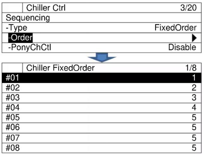
flowchart
graph TD
    A["Chiller Ctrl 3/20"] --> B["Sequencing"]
    B --> C["-Type FixedOrder"]
    C --> D["-Order ▶"]
    D --> E["-PonyChCtl Disable"]
    F["Chiller FixedOrder 1/8"] --> G["#01 1"]
    G --> H["#02 2"]
    H --> I["#03 3"]
    I --> J["#04 4"]
    J --> K["#05 5"]
    K --> L["#06 5"]
    L --> M["#07 5"]
    M --> N["#08 5"]
9.1.2. Setting detailed options for staging up / down
- From "MainMenu > Setting > DeviceCtrlParam > Chiller Ctrl" screen, follow below steps to reach "ChillerStg Detail" screen. Here, detailed settings for each method of staging up / down can be done.
| ChillerCtrlParam | 14/20 | |
| -MinRunningCh | 1 | |
| -MaxRunningCh | 1 | |
| -Detail | ▶ | |
| StabilizeTime | ||

| ChillerStg Detail | 1/14 | |
| StgByLoadLimit | ||
| -StgUpWaitTime | 180s | |
| -StgDnWaitTime | 10min | |
| -Full/LowLoad Setting | ▶ | |
| StgByTemp | ||
| -StgUpWaitTime | 5min | |
| -StgDnWaitTime | 5min | |
| -StgUpDiff | 1.0 dK | |
| -StgDnDelta | 3.5 D°C | |
| -WaitTime(SuddenLoad) | 6min | |
| -TempDiff(SuddenLoad) | 1.0 dK | |
| StgByTargetLoad | ||
| -TargetLoad | 50% | |
| -StgUpWaitTime | 180s | |
← a.
← b.
← 9.1.2.1 Setting full / low load for each chiller
← C.
← d.
← e.
← f.
← g.
← h.
← i.
← j.
Table 26 List of parameters which can be set from “Chiller StgUpToOptimal” screen
| ID | Name | Definition | |
| a. | -StgUpWaitTime | 1...600 sec | Wait time BEFORE stage up based on full load is confirmed |
| b. | -StgDnWaitTime | 1...600 sec | Wait time BEFORE stage down based on low load is confirmed |
| c. | -StgUpWaitTime | 1...30 min | Wait time BEFORE stage up based on chilled water temperature is confirmed |
| d. | -StgDnWaitTime | 1...30 min | Wait time BEFORE stage down based on chilled Delta temperature is confirmed |
| e. | -StgUpDiff | 0.0...5.0 dK | Temperature differential for deciding threshold of stage up based on Supply water temperature |
| f. | -StgDnDelta | 0.0...99.0 D°C | DELTA Temperatura (EWT-LWT) for deciding setpoint below that staging down will be confirmed |
| g. | -WaitTime(SuddenLoad) | 1...30 min | Base Wait time BEFORE stage up based on chilled water temperature (sudden load) |
| h. | -TempDiff(SuddenLoad) | 0.0...5.0 dK | Temperature differential for deciding threshold of staging based on supply water temperature (sudden load) |
| i. | -TargetLoad | 1...100% | Target optimal load target for chiller when using staging up based on optimal chiller load |
| j. | -StgUpWaitTime | 1...600 sec | Wait time BEFORE stage up based on optimal chiller load is confirmed |
9.1.2.1. Setting full / low load for each chiller
- From "MainMenu > Setting > DeviceCtrlParam > ChillerCtrlParam > ChillerStg Detail" screen, follow below steps to reach "Full/LowLoadSetting" screen. Here, full load and low load setting for each chiller can be done.
| ChillerStg Detail | 4/14 | |
| Full/LowLoad Setting | ▶ | |
| StgByTemp | ||
| -StgUpWaitTime | 5min | |
| -StgDnWaitTime | 5min | |
| Full/LowLoadSetting | 1/24 | |
| #01 | ||
| -FullLoad | 90% | |
| -LowLoad | 10% | |
| #02 | ||
| -FullLoad | 90% | |
| -LowLoad | 10% | |
| #03 | ||
| -FullLoad | 90% | |
| LowLoad | 10% | |
| #04 | ||
| -FullLoad | 90% | |
| -LowLoad | 10% | |
| #05 | ||
| -FullLoad | 90% | |
| -LowLoad | 10% | |
| #06 | ||
| -FullLoad | 90% | |
| -LowLoad | 10% | |
| #07 | ||
| -FullLoad | 90% | |
| -LowLoad | 10% | |
| #08 | ||
| -FullLoad | 90% | |
| -LowLoad | 10% | |
NOTE: Please DO NOT set LowLoad threshold higher than FullLoad threshold.
9.2. Primary Pump Control Setting
(Used screen: MainMenu > Setting > DeviceCtrlParam > PrimaryPump Ctrl)
- From "DeviceCtrlParam" screen, turn the click-dial to select "PrimaryPump" menu then press down on the click-dial to jump to "PrimaryPump Ctrl" screen.
| DeviceCtrlParam | 2/5 | |
| Chiller | ▶ | |
| PrimaryPump | ▶ | |
| BypassValve | ▶ | |
| CondenserPump | ▶ | |
- "PrimaryPump Ctrl" screen is displayed. Here, various options for primary pump control can be set.
| PrimaryPump Ctrl | 1/14 | |
| PumpType | CSD | |
| Setpt | 13kPa | |
| -ActiveValue | 13kPa | |
| VFD_Control | ||
| -MaxCapacity | 100% | |
| -MinCapacity | 30% | |
| -PI_Param | ▶ | |
| Staging | ||
| -StgUpWaitTime | 60s | |
| -StgDnWaitTime | 60s | |
| -StgUpDiff | 20kPa | |
| -StgDnDiff | 20kPa | |
| -StgForRotation | ▶ | |
| OperationRange | ▶ | |
← 9.2.2 Setting periodical pump staging for rotation
← 9.2.3 Setting minimum / maximum number of operating pumps for each piping group
Table 27 List of Parameters which can be Set from "PrimaryPump Ctrl" screen
| ID | Name | Definition | |
| a. | PumpType | VDF CSD | Set to VFD when VFD control of pumps is needed Set to CSD if constant flow is needed |
| b. | Setpt | 1...999 kPa | Target setpoint for VFD / CSD pump control |
| c. | -ActiveValue | Status display of actual setpoint (for future optimization control) | |
| d. | MaxCapacity | 0...100 % | Maximum output for VFD control |
| e. | MinCapacity | 0...100 % | Minimum output for VFD control |
| f. | -StgUpWaitTime | 1...600 sec | Wait time BEFORE stage up is confirmed |
| g. | -StgDnWaitTime | 1...600 sec | Wait time BEFORE stage down is confirmed |
| h. | -StgUpDiff | 0...100 kPa | Pressure differential for deciding threshold of CSD pump staging up |
| i. | -StgDnDiff | 0...100 kPa | Pressure differential for deciding threshold of CSD pump staging down |
9.2.1. Setting PI Parameters for Pump VFD Control
- From "MainMenu > Setting > DeviceCtrlParam > PrimaryPump Ctrl" screen, follow below steps to reach "PriPpDiffPress PI_Param" screen. Here, PI parameter for pump VFD control can be set.
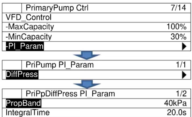
flowchart
graph TD
    A["PrimaryPump Ctrl 7/14"] --> B["VFD_Control"]
    B --> C["-MaxCapacity 100%"]
    C --> D["-MinCapacity 30%"]
    D --> E["-PI_Param"]
    E --> F["DiffPress"]
    F --> G["PriPump PI_Param 1/1"]
    G --> H["PropBand 40kPa"]
    H --> I["IntegralTime 20.0s"]
Table 28 List of parameters which can be set from "PrimaryPump Ctrl" screen
| ID | Name | Definition | |
| a. | PropBand | 0...999 kPa | Proportional band setting of PI control |
| b. | IntegralTime | 0.0...999.0 sec | Integral time setting of PI control |
9.2.2. Setting periodical pump staging for rotation
- From "MainMenu > Setting > DeviceCtrlParam > PrimaryPump Ctrl" screen, follow below steps to reach "StgForRotation" screen. Here, periodical pump staging for rotation can be set.
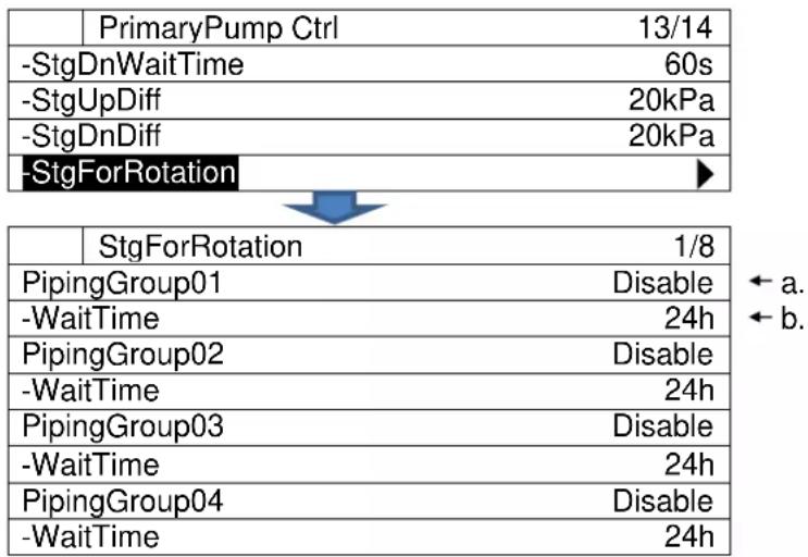
flowchart
graph TD
    A["PrimaryPump Ctrl 13/14"] --> B["-StgDnWaitTime 60s"]
    B --> C["-StgUpDiff 20kPa"]
    C --> D["-StgDnDiff 20kPa"]
    D --> E["-StgForRotation ▶"]
    F["StgForRotation 1/8"] --> G["PipingGroup01 Disable ← a."]
    F --> H["-WaitTime 24h ← b."]
    G --> I["PipingGroup02 Disable"]
    G --> J["-WaitTime 24h"]
    I --> K["PipingGroup03 Disable"]
    I --> L["-WaitTime 24h"]
    K --> M["PipingGroup04 Disable"]
    K --> N["-WaitTime 24h"]
Table 29 List of parameters which can be set from "StgForRotation" screen
| ID | Name | Definition | |
| a. | PipingGroup[X] | Enable Disable | Enable / disable periodical staging for rotation |
| b. | -WaitTime | 24...720 h | How long to wait before conducting staging for rotation |
9.2.3. Setting minimum / maximum number of operating pumps for each piping group
From "MainMenu > Setting > DeviceCtrlParam > PrimaryPump Ctrl" screen, follow below steps to reach "OperationRange" screen. Here, minimum / maximum number of operating pumps for each piping group can be set.
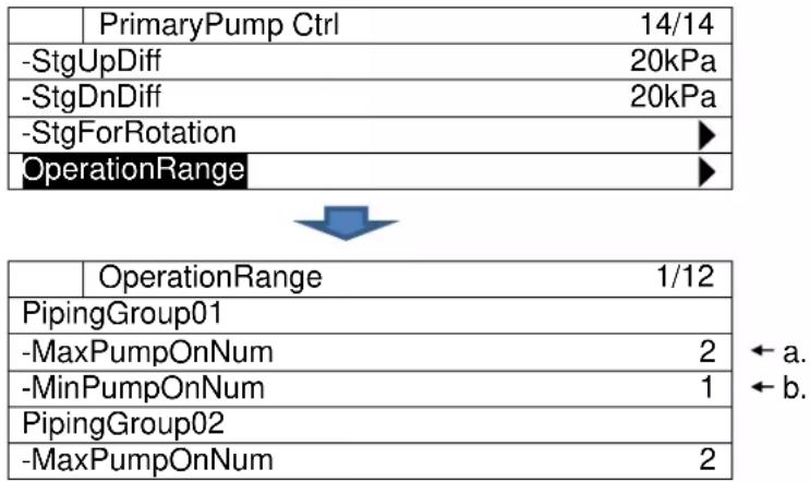
flowchart
graph TD
    A["PrimaryPump Ctrl 14/14"] --> B["-StgUpDiff 20kPa"]
    B --> C["-StgDnDiff 20kPa"]
    C --> D["-StgForRotation ▶"]
    D --> E["OperationRange ▶"]
    E --> F["OperationRange 1/12"]
    F --> G["PipingGroup01"]
    G --> H["-MaxPumpOnNum 2"]
    H --> I["-MinPumpOnNum 1"]
    I --> J["PipingGroup02"]
    J --> K["-MaxPumpOnNum 2"]
| -MinPumpOnNum | 2 |
| PipingGroup03 | |
| -MaxPumpOnNum | 3 |
| -MinPumpOnNum | 0 |
| PipingGroup04 | |
| -MaxPumpOnNum | 4 |
| -MinPumpOnNum | 4 |
Table 30 List of parameters which can be set from "OperationRange" screen
| ID | Name | Definition |
| a. | MaxPumpOnNum | Maximum number of operating pumps for each piping group setting |
| b. | MinPumpOnNum | Minimum number of operating pumps for each piping group setting |
NOTE: Please set this value "a" bigger than "b".
9.3. Bypass Valve Control Setting
(Used screen: MainMenu > Setting > DeviceCtrlParam > BypasValve Ctrl)
- From "DeviceCtrlParam" screen, turn the click-dial to select "BypassValve" menu then press down on the click-dial to jump to "BypassValve Ctrl" screen.
| DeviceCtrlParam | 3/5 | |
| Chiller | ▶ | |
| PrimaryPump | ▶ | |
| BypassValve | ▶ | |
| CondenserPump | ▶ | |
- "Bypass Ctrl" screen is displayed. Here, various options for bypass valve control can be set.
| BypassValve Ctrl | 1/4 | |
| MaxCapacity | 100% | |
| MinCapacity | 0% | |
| PI_Param | ||
| -DiffPress | ▶ | |
← a.
← b.
← 9.3.1 Setting PI Parameters for Bypass Valve Control
Table 31 List of parameters which can be set from “BypassValve Ctrl” screen
| ID | Name | Definition | |
| a. | MaxCapacity | 0...100 % | Maximum output value for PI control |
| b. | MinCapacity | 0...100 % | Minimum output value for PI control |
9.3.1. Setting PI Parameters for Bypass Valve Control
- From "MainMenu > Setting > DeviceCtrlParam > BypassValve Ctrl" screen, follow below steps to reach "BypValveDiffPress PI-Pa" screen. Here, PI parameter for bypass valve control can be set.
| BypassValve Ctrl | 4/4 | |
| MaxCapacity | 100% | |
| MinCapacity | 0% | |
| PI_Param | ||
| DiffPress | ▶ | |

| BypValveDiffPress PI_Pa | 1/5 | |
| DiffPress | ||
| -Setpt | 13kPa | |
| -ActiveValue | 13kPa | |
| -PropBand | 50kPa | |
| -IntegralTime | 60.0s | |
← a.
← b.
← C.
← d
Table 32 List of parameters which can be set from "BypValveDiffPress PI_Pa" screen
| ID | Name | Definition | |
| a. | -Setpt | 1...999 kPa | Target setpoint for bypass valve control |
| b. | -ActiveValue | Status display of actual setpoint (for future optimization control ) | |
| c. | -PropBand | 0...999 kPa | Proportional band setting of PI control |
| d | -IntegralTime | 0.0...999.0 sec | Integral time setting of PI control |
9.4. Condenser Pump Control Setting
(Used screen: MainMenu > Setting > DeviceCtrlParam > CondenserPump Ctrl)
- From "DeviceCtrlParam" screen, turn the click-dial ⏻ to select "CondenserPump" menu then press down on the click-dial ⏻ to jump to "CondenserPump Ctrl" screen.
| DeviceCtrlParam | 4/5 | |
| PrimaryPump | ▶ | |
| BypassValve | ▶ | |
| CondenserPump | ▶ | |
| CTBypassValve | ▶ | |
- "CondenserPump Ctrl" screen is displayed. Here, various options for condenser pump control can be set.
| CondenserPump Ctrl | 1/4 | |
| CndPipingGroup1 | ▶ | |
| CndPipingGroup2 | ▶ | |
| CndPipingGroup3 | ▶ | |
| CndPipingGroup4 | ▶ | |
- For each "CondenserPump Ctrl", press down on the click-dial Ⓞ to jump to "CndPump Ctrl" screen, which is shown below. (Example shown is CndPipingGroup1)
| Gr1 CndPump Ctrl | 1/21 | |
| PumpType | VFD | |
| CtrlType | DiffTemp | |
| SetptDiffTemp | 5.0°C | |
| -ActiveValue | 5.0°C | |
| SetptDiffPress | 13kPa | |
| -ActiveValue | 13kPa | |
| VFD Control | ||
| -MaxCapacity | 100% | |
| -MinCapacity | 0% | |
| -DT_PI_Param | ▶ | |
| -DP_PI_Param | ▶ | |
| Staging | ||
| -StgUpWaitTime | 60s | |
| -StgDnWatTme | 60s | |
| -StgUpDiffTemp | 1.0°C | |
| -StgDnDiffTemp | 1.0°C | |
| -StgUpDiffPress | 5kPa | |
| -StgDnDiffPress | 5kPa | |
| -StgForRotation | Enable | |
| -WaitTime | 24h | |
| -OperationRange | ▶ | |
← a.
← b.
← C.
← d.
← e.
← f.
← g.
← h.
← 9.4.1 Setting DT_PI Parameters for Pump VFD Control
← 9.4.2 Setting DP_PI Parameters for Pump VFD Control
← i.
← i.
← k.
← |.
← m.
← n.
← 0.
← p.
← 9.4.3 Setting minimum / maximum number of operating pumps for each piping group
Table 33 List of parameters which can be set from "CndPump Ctrl" screen
| ID | Name | Definition | |
| a. | PumpType | VDFCSD | Set to VFD when VFD control of pumps is neededSet to CSD if constant flow is needed |
| b. | CtrlType | 1...999 kPa | Select from temperature differential or pressure differential |
| c. | SetptDiffTemp | 0.0...99.0D°C | Target setpoint of temperature differential for VFD / CSD pump control |
| d. | -ActiveValue | Status display of actual setpoint (for future optimization control ) | |
| e. | SetptDiffPress | 0...999 kPa | Target setpoint of pressure differential for VFD / CSD pump control |
| f. | -ActiveValue | Status display of actual setpoint (for future optimization control ) | |
| g. | -MaxCapacity | 0...100 % | Maximum output for VFD control |
| h. | -MinCapacity | 0...100 % | Minimum output for VFD control |
| i. | -StgUpWaitTime | 1...600 sec | Wait time BEFORE stage up is confirmed |
| j. | -StgDnWatTme | 1...600 sec | Wait time BEFORE stage down is confirmed |
| k. | -StgUpDiffTemp | 0.0...99.0 dK | Temperature differential for deciding threshold of CSD pump staging up |
| l. | -StgDnDiffTemp | 0.0...99.0 dK | Temperature differential for deciding threshold of CSD pump staging down |
| m. | -StgUpDiffPress | 0...100 kPa | Pressure differential for deciding threshold of CSD pump staging up |
| n. | -StgDnDiffPress | 0...100kPa | Pressure differential for deciding threshold of CSD pump staging down |
| o. | -StgForRotation | Enable/disable staging for rotation | |
| p. | -WaitTime | 24...720 h | Wait time BEFORE staging is confirmed |
9.4.1. Setting DT\_PI Parameters for Pump VFD Control
- From "MainMenu > Setting > DeviceCtrlParam > CondenserPump Ctrl" screen, follow below steps to reach "Gr# CndPpDT_PI_Param" screen. Here, PI parameter for pump VFD control can be set. (Gr1 is shown as an example.)
| Gr1 CndPump Ctrl | 10/21 | |
| VFD_Control | ||
| -MaxCapacity | 100% | |
| -MinCapacity | 0% | |
| DT_PI_Param | ||

| Gr1 CndPpDT PI Param | 1/2 | |
| PropBand | 10.0°C ← a. | |
| IntegralTime | 20.0s ← b. | |
Table 34 List of parameters which can be set from "PrimaryPump Ctrl" screen
| ID | Name | Definition |
| a. | PropBand | Proportional band setting of PI control |
| b. | IntegralTime | Integral time setting of PI control |
9.4.2. Setting DP\_PI Parameters for Pump VFD Control
- From "MainMenu > Setting > DeviceCtrlParam > CondenserPump Ctrl" screen, follow below steps to reach "Gr# CndPpDP_PI_Param" screen. Here, PI parameter for pump VFD control can be set. (Gr1 is shown as an example.)
| Gr1 CndPump Ctrl | 11/21 | |
| -MaxCapacity | 100% | |
| -MinCapacity | 0% | |
| -DT_PI_Param | ▶ | |
| DP_PI_Param | ▶ | |

| Gr1 CndPpDP PI Param | 1/2 | |
| PropBand | 10kPa | |
| IntegralTime | 20.0s | |
Table 35 List of parameters which can be set from "PrimaryPump Ctrl" screen
| ID | Name | Definition |
| a. | PropBand | Proportional band setting of PI control |
| b. | IntegralTime | Integral time setting of PI control |
9.4.3. Setting minimum / maximum number of operating pumps for each piping group
- From "MainMenu > Setting > DeviceCtrlParam > CondenserPump Ctrl" screen, follow below steps to reach "OperationRange" screen. Here, minimum / maximum number of operating pumps for each piping group can be set.
| PrimaryPump Ctrl | 21/21 | |
| -StgDnDffPress | 5kPa | |
| -StgForRotation | Enable | |
| -WaitTime | 24h | |
| -OperationRange | ▶ | |
| Gr1 OperationRange | 1/2 | |
| MaxPumpOnNum | 2 | |
| MinPumpOnNum | 1 | |
Table 36 List of parameters which can be set from "OperationRange" screen
| ID | Name | Definition |
| a. | MaxPumpOnNum | Minimum number of operating pumps for each piping group setting |
| b. | MinPumpOnNum | Maximum number of operating pumps for each piping group setting |
NOTE: Please DO NOT set value "b" bigger than "a".
9.5. Cooling Tower Bypass Valve Control Setting
(Used screen: MainMenu > Setting > DeviceCtrlParam > CTBypasValve Ctrl)
- From "DeviceCtrlParam" screen, turn the click-dial ⏻ to select "CTBypassValve" menu then press down on the click-dial ⏻ to jump to "CTBypassValve Ctrl" screen.
| DeviceCtrlParam | 5/5 | |
| PrimaryPump | ▶ | |
| BypassValve | ▶ | |
| CondenserPump | ▶ | |
| CTBypassValve | ▶ | |
- "CTBypass Ctrl" screen is displayed. Here, various options for bypass valve control can be set.
| CTBypassValve Ctrl | 1/4 | |
| CndPipingGroup1 | ▶ | |
| CndPipingGroup2 | ▶ | |
| CndPipingGroup3 | ▶ | |
| CndPipingGroup4 | ▶ | |
- Turn the click-dial Ⓞ to select "Gr# CTBypassValve Ctrl" menu for each condenser piping group number, then then press down on the click-dial to 'hmp to the' screen. (Gr1 is shown as an example)
| Gr1 CTBypassValve Ctrl | 1/4 | |
| MaxCapacity | 100% | |
| MinCapacity | 0% | |
| PI Param | ||
| -CndWtEntTemp | ▶ | |
Table 37 List of parameters which can be set from "CTBypassValve Ctrl" screen
| ID | Name | Definition |
| a. | MaxCapacity | Maximum output value for PI control |
| b. | MinCapacity | Minimum output value for PI control |
9.5.1. Setting PI Parameters for Cooling Tower Bypass Valve Control
- From "MainMenu > Setting > DeviceCtrlParam > CTBypassValve Ctrl>Gr# CTBypassValve Ctrl" screen, follow below steps to reach "CTBypValveDiffPress PI-Pa" screen. Here, PI parameter for bypass valve control can be set.
| Gr1 CTBypassValve Ctrl | 4/4 | |
| MaxCapacity | 100% | |
| MinCapacity | 0% | |
| PI Param | ||
| CndWtEntTemp | ▶ | |
| Gr1 CTBypValve_PI_Param | 1/5 | |
| CndWtEntTemp | ||
| -Setpt | 13kPa | ← a. |
| -ActiveValue | 13kPa | ← b. |
| -PropBand | 50kPa | ← c. |
| -IntegralTime | 60.0s | ← d. |
Table 38 List of parameters which can be set from "CTBypValveDiffPress PI_Pa" screen
| ID | Name | Definition |
| a. | -Setpt | Target setpoint for bypass valve control |
| b. | -ActiveValue | Status display of actual setpoint (for future optimization control ) |
| c. | -PropBand | Proportional band setting of PI control |
| d | -IntegralTime | Integral time setting of PI control |
9.6. System Control Setting
Setting of various control parameters for system control can be done from this menu.
Menu structure and items which can be set are described below.
□MainMenu
○ Setting
- SystemCtrlParam
□ SystemCtrlParam
PowerFailureRecov....Set parameters for power failure recovery control
- DblTempSetpt....Set parameters for double setpoint control
○ ProtectSystem ....Set pump frequency when recycling, pump frequency for
force pump on, chiller on delay time, pump off delay time etc.
- PullDownRateCtrl...... Set parameters for pull down rate control
- SetptReset....Set parameters for setpoint reset
- Press the Home Button ☐ to show the "MainMenu" screen.
| MainMenu | 1/4 | |
| Status | ▶ | |
| Setting | ▶ | |
| ConfigMode | ▶ | |
| Password | ▶ | |
- On the "MainMenu" screen, turn the click-dial Ⓞ to select "Setting" menu then press down on the click-dial Ⓞ to jump to "Setting" screen.
| MainMenu | 2/4 | |
| Status | ▶ | |
| Setting | ▶ | |
| ConfigMode | ▶ | |
| Password | ▶ | |
- On the "Setting" screen, turn the click-dial ⏻ to select "SystemCtrlParam" menu then press down on the click-dial ⏻ to jump to "SystemCtrlParam" screen.
| Setting | 1/5 | |
| SystemCtrlParam | ▶ | |
| DeviceCtrlParam | ▶ | |
| CtrlModeSetting | ▶ | |
| SystemSetting | ▶ | |
- SystemCtrlParam screen is shown. From this screen, you can jump to control parameter setting for different system control.
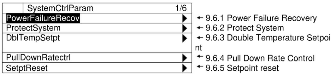
9.6.1. Power Failure Recovery
(Used screen: MainMenu > Setting > SystemCtrlParam > PowerFailureRecov)
- From "SystemCtrlParam" screen, turn the click-dial ⏻ to select "PowerFailureRecov" menu then press down on the click-dial ⏻ to jump to "PowerFailureRecov" screen.
| SystemCtrlParam | 1/6 | |
| PowerFailureRecov | ▶ | |
| ProtectSystem | ▶ | |
| DblTempSetpt | ▶ | |
| PullDownRateCtrl | ▶ | |
- "PowerFailureRecov" screen is shown. Here, parameters for power failure recovery control can be set.
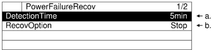
Table 39 List of parameters which can be set from "PowerFailureRecov" screen
| ID | Name | Definition |
| a. | DetectionTime | Power off duration to judge power failure (if power off time is less than this setting, it is considered power failure) |
| b. | RecovOption | Behaviour of iCM when recovering from power failure. (Always recover from stop / restore sysmte ON/OFF status before power off) |
9.6.2. Protect System
(Used screen: MainMenu > Setting > SystemCtrlParam > ProtectSystem)
- From "SystemCtrlParam" screen, turn the click-dial to select "ProtectSystem" menu then press down on the click-dial to jump to "ProtectSystem" screen.
| SystemCtrlParam | 2/6 | |
| PowerFailureRecov | ▶ | |
| ProtectSystem | ▶ | |
| DblTempSetpt | ▶ | |
| PullDownRateCtrl | ▶ | |
- "ProtectSystem" screen is shown. Here, parameters for system protection control can be set.
| ProtectSystem | 1/18 | |
| KeepMinEvaFlwCap | 20% | |
| ForcePriPpModeCap | 40% | |
| ChillerOnDelayTime | 60s | |
| ChillerOffDelayTime | 180s | |
| PumpOnDelayTime | 60s | |
| PumpOffDelayTime | 60s | |
| ValveOpenDelayTime | 180s | |
| RecycleDelayTime | 360s | |
| KeepMinCndFlowCap | 20% | |
| ForceCndPpModeCap | 40% | |
| CndPumpOnDelayTime | 60s | |
| CndPumpOffDelayTime | 60s | |
| CndValveOpenDelayTime | 60s | |
| CndValveCloseDelayTime | 180s | |
| CTValveOpenDelayTime | 60s | |
| CTValveCloseDelayTime | 180s | |
| CTFanOnDelayTime | 60s | |
| CTFanOffDelayTime | 180s | |
Table 40 List of parameters which can be set from "ProtectSystem" screen
| ID | Name | Definition |
| a. | KeepMinEvaFlwCap | Minimum VFD frequency for primary pump control to ensure minimum flow |
| b. | ForcePriPpModeCap | VFD frequency when using force pump on control |
| c. | ChillerOnDelayTime | Delay time after chiller ON Status to operate auxiliaries |
| d. | ChillerOffDelayTime | Delay time after chiller OFF Status to stop auxiliaries |
| e. | PumpOnDelayTime | Delay time after pump ON Status to operate auxiliaries |
| f. | PumpOffDelayTime | Delay time after pump OFF Status to stop auxiliaries |
| g. | ValveOpenDelayTime | Delay time after valve OPEN Status to operate chillers |
| h. | RecycleDelayTime | Delay time to operate auxiliaries after last chiller stops |
| i. | KeepMinCndFlowCap | Minimum condenser flow capacity |
| j. | ForceCndPpModeCap | Capacity when forced condenser pump mode is on |
| k. | CndPumpOnDelayTime | Delay time to operate auxiliaries after condenser pump runs |
| l. | CndPumpOffDelayTime | Delay time to operate auxiliaries after condenser pump stops |
| m. | CndValveOpenDelayTime | Delay time to operate auxiliaries after condenser valve operates |
| n. | CndValveCloseDelayTime | Delay time to operate auxiliaries after condenser valve stops |
| o. | CTValveOpenDelayTime | Delay time to operate auxiliaries after condenser pump operates |
| p. | CTValveCloseDelayTime | Delay time to operate auxiliaries after condenser pump stops |
| q. | CTFanOnDelayTime | Delay time to operate auxiliaries after cooling tower fan operates |
| r. | CTFanOffDelayTime | Delay time to operate auxiliaries after cooling tower fan stops |
9.6.3. Double Temperature Setpoint
(Used screen: MainMenu > Setting > SystemCtrlParam > DblTempSetpt)
NOTE: Source of input setting for chilled water temperature setpoint needs to be “Control” for double temperature setpoint to work correctly. This is described in detail on Table 41.
Table 41 Setting vs. chilled water temperature output of double setpoint control
| Setting | Chilled water temperature output | ||
| Source of input | Enable / Disable | External Signal | |
| Control | Enable | ON | Double Setpoint setting |
| OFF | Chilled water temperature setpoint from HMI | ||
| Disable | Don't care | ||
| Other | Don't' care | Don't care | Value from configured source of setting |
- From "SystemCtrlParam" screen, turn the click-dial to select "DblTempSetpt" menu then press down on the click-dial to jump to "DblTempSetpt" screen.
| SystemCtrlParam | 3/6 |
| PowerFailureRecov | ▶ |
| ProtectSystem | ▶ |
| DblTempSetpt | ▶ |
| PullDownRateCtrl | ▶ |
- "DblTempSetpt" screen is shown. Here, parameters for double setpoint control can be set.
| DblTempSetpt | 1/2 | |
| DblSptEnable | Disable | |
| DblTempSetpt | 5.0°C | |
Table 42 List of parameters which can be set from "ProtectSystem" screen
| ID | Name | Definition |
| a. | DblSptEnable | Enable / disable double setpoint control. When enabled, actual setpoint will become value specified by double setpoint when receiving I/O signal.Note: when double setpoint is enabled but not external signal from I/O, chilled water temperature set from HMI will be used. |
| b. | DblTempSetpt | Set value of double setpoint |
9.6.4. Pull Down Rate Control
(Used screen: MainMenu > Setting > SystemCtrlParam > PullDownRateCtrl)
Image of pull down rate control is shown on Figure 13
Stage up is inhibited when pull down rate exceeds Threshold 1 setting. Staging is allowed again when pull down rate becomes lower than Threshold 2 setting. Pull down rate is calculated every so often specified by measure band setting.
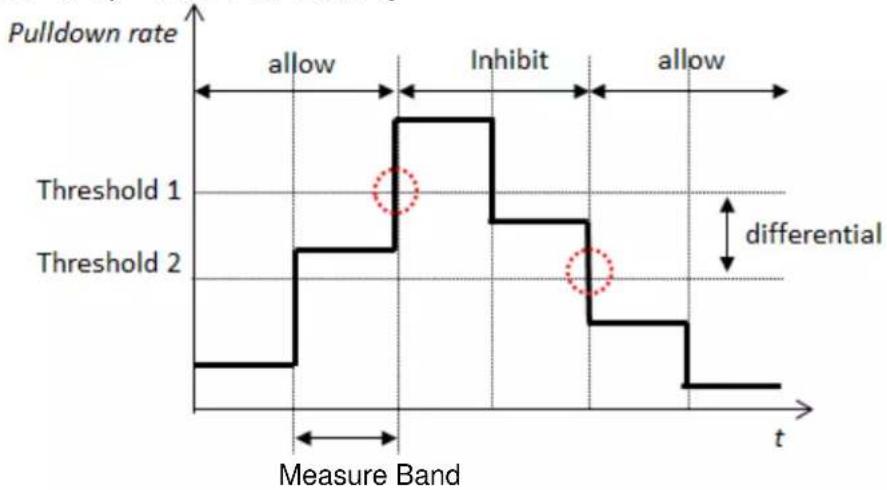
line
| Measure Band | Pulldown rate | | ------------ | ------------- | | lower | lower | | lower | higher | | upper | lower | | lower | higher | | upper | lower |Figure 13 Pull Down Rate Control
- From "SystemCtrlParam" screen, turn the click-dial ☐ to select "PullDownRateCtrl" menu then press down on the click-dial ☐ to jump to "PullDownRateCtrl" screen.
| SystemCtrlParam | 4/6 | |
| PowerFailureRecov | ▶ | |
| ProtectSystem | ▶ | |
| DblTempSetpt | ▶ | |
| PullDownRateCtrl | ▶ | |
- "PullDownRateCtrl" screen is shown. Here, parameters for pull down rate control can be set.
| PullDownRateCtrl | 1/5 | |
| PIDnRateEnable | Disable ← a. | |
| TargetWtTemp | EWT ← b. | |
| MeasureBand | 60s ← c. | |
| PIDnRateUpLimit | 0.5° C / min | |
| PIDnRateOffset | 0.1° C / min | |
Table 43 List of parameters which can be set from "PullDownRateCtrl" screen
| ID | Name | Definition |
| a. | PIDnRateEnable | Enable / Disable pull down rate control |
| b. | TargetWtTemp | Use entering water temperature or leaving water temperature to calculated pull down rate |
| c. | MeasureBand | Window time duration to calculate pull down rate |
| d. | PIDnRateUpLimit | Upper limit of pull down rate before inhibiting stage up |
| e. | PIDnRateOffset | Differential value subtracted from upper limit when judging unlock of stage up |
9.6.5. Setpoint reset
(Used screen: MainMenu > Setting > SystemCtrlParam > Setpt Reset)
- From "SystemCtrlParam" screen, turn the click-dial to select "Setpt Reset" menu then press down on the click-dial to jump to "PullDownRateCtrl" screen.
| SystemCtrlParam | 5/6 | |
| DbITempSetpt | ▶ | |
| PullDownRatectrl | ▶ | |
| SetptReset | ▶ | |
- "Setpt Reset" screen is shown. Here, parameters for setpoint reset can be set.
| SetptReset | 1/5 | |
| ResetEnable | Enable ← a. | |
| TargetTemp | OAT ← b. | |
| SetptDiff | 5.0°C ← c. | |
| MaxReset | 15.0°C ← d. | |
| NoReset | 25.0°C | ←e. |
Table 44 List of parameters which can be set from "Setpt Reset" screen
| ID | Name | Definition |
| a. | ResetEnable | Enable / Disable setpoint reset |
| b. | Target Temp | Use outdoor air temperature or cooled water return temperature to calculate setpoint reset |
| c. | SetptDiff | Temprature differential when executing setpoint reset |
| d. | MaxReset | Maximum temperature to enable setpoint reset |
| e. | NoReset | Tempreature setpoint to disable setpoint reset |
9.7. Source of Input Setting
It is possible to specify, for each setpoint / command, which input to be effective. Setting of which source of input to be active for each item can be done from this menu.
Menu structure and items which can be set are described below.
□MainMenu
○ Setting
- CtrlModeSetting
CtrlModeSetting
- Run/Stop....Set source of input for Run/Stop command
TempSetpt....Set source of input for chilled water temperature - ForcePriPumpMode ....Set source of input for force primary pump on command
○ ForceCondPumpMode......Set source of input for force condenser pump on command
o PriPpDiffPressSetpt ....Set source of input for primary pump VFD differential pressure setpoint
Gr# CndPpCtrlSetpt....Set source of input for condenser pump piping group control
setpoint for each group (1 to 4)
○ BpVlvDiffPressSetpt......Set source of input for bypass valve differential pressure
Setpoint
Gr# CndBpVlvTempSetpt....Set source of input for condenser bypass valve temperature
setpoint for condenser piping group (1 to 4)
Steps for selecting source of input are described below
- Press the Home Button ☐ to show the "MainMenu" screen.
| MainMenu | 1/4 | |
| Status | ▶ | |
| Setting | ▶ | |
| ConfigMode | ▶ | |
| Password | ▶ | |
- On the "MainMenu" screen, turn the click-dial Ⓞ to select "Setting" menu then press down on the click-dial Ⓞ to jump to "Setting" screen.
| MainMenu | 2/4 | |
| Status | ▶ | |
| Setting | ▶ | |
| ConfigMode | ▶ | |
| Password | ▶ | |
- On the "Setting" screen, turn the click-dial to select "CtrlModeSetting" then press down on the click-dial to jump to "CtrlModeSetting" screen.
| Setting | 3/5 | |
| SystemCtrlParam | ▶ | |
| DeviceCtrlParam | ▶ | |
| CtrlModeSetting | ▶ | |
| SystemSetting | ▶ | |
- On the "CtrlModeSetting" screen, source of input for various commands can be changed. Please refer to Table 44 for available source of input for each command.
| CtrlModeSetting | 1/12 | |
| Run/Stop | Manual | |
| TempSetpt | Manual | |
| ForcePriPumpMode | Manual | |
| ForceCondPumpMode | Manual | |
| PriPpDiffPressSetpt | Manual | |
| Gr1CndPpCtrlSetpt | Manual | |
| Gr2CndPpCtrlSetpt | Manual | |
| Gr3CndPpCtrlSetpt | Manual | |
| Gr4CndPpCtrlSetpt | Manual | |
| BpVlvDiffPressSetpt | Manual | |
| Gr1CndBpVlvTempSetpt | Manual | |
| Gr2CndBpVlvTempSetpt | Manual | |
| Gr3CndBpVlvTempSetpt | Manual | |
| Gr4CndBpVlvTempSetpt | Manual | |
Name of command
Manual: Manual Input from HMI is valid
I/O: Input from I/O is valid
Control: Input from internal control such as double setpoint is valid,
BACnet: Input from BACnet is valid
AutoCloud: Input from cloud is valid (for future use)
Table 45 illustrates available source of input for each command.
Table 45 List of Available Source of Input for Each Command
| Name | Descripon | Manual | Auto | |||
| I/O | Control | BACnet | AutoCloud | |||
| Run/Stop | Run/Stop command | Y | Y | N | Y | Y |
| TempSetpt | Chilled water temperature setpoint | Y | Y | Y | Y | Y |
| ForcePriPumpMode | Force primary pump on command | Y | Y | N | Y | Y |
| ForceCondPumpMode | Force condenser pump on command | Y | Y | N | Y | Y |
| PriPpDiPressSetpt | Dierenal pressure setpoint for primary pump VFD control | Y | N | N | N | Y |
| CndPpCtrlSetpt | Condenser pump control setpoint | Y | N | N | N | Y |
| BpVlvDiPressSetpt | Dierenal pressure setpoint for bypass valve control | Y | N | N | N | Y |
| CndBpVlvTempSetpt | Temperature setpoint for condenser side bypass valve | Y | N | N | N | Y |
CAUTION: Please DO NOT set control mode to source of input shown as "N": NOT available" (e.g. Setting Control as source of input for Run/Stop). Resulting output and iCM behaviour is not guaranteed.
10. Trial Run
Sending command manually to various equipment in order to check connection can be done from this menu.
Note: the system needs to be in "Config Mode" when using trial run menu.
Menu structure and items which can be set are described below.
□MainMenu
○ ConfigMode ■ Trialrun
TrialRun
○ Chiller ...... Send temperature setpoint manually to chiller
- I/O....Check connection of each ext. module, check input of each
input I/O port, and send manual signal from each output I/O port
○ BACnet_Module......Check connection status of BACnet Module.
- Press the Home Button ☐ to show the "MainMenu" screen.
| MainMenu | 1/4 | |
| Status | ▶ | |
| Setting | ▶ | |
| ConfigMode | ▶ | |
| Password | ▶ | |
- On the "MainMenu" screen, turn the click-dial to select "ConfigMode" menu then press down on the click-dial to jump to "ConfigMode" screen.
| MainMenu | 3/4 | |
| Status | ▶ | |
| Setting | ▶ | |
| ConfigMode | ▶ | |
| Password | ▶ | |
- On the "ConfigMode" screen, turn the click-dial to select "TrialRun" menu then press down on the click-dial to jump to "TrialRun" screen.
| ConfigMode | 5/8 | |
| TrialRun | ▶ | |
| Backup/Restore | ▶ | |
| DataManagement | ▶ | |
| Reset | - | |
- "TrialRun" screen is shown. From this screen, you can jump to trial run menu of different equipment.
| TrialRun | 1/4 | |
| Chiller | ← 10.1 Chiller Trial Run | |
| I/O | ← 10.2 I/O Trial Run | |
| BACnet Module | NoError | ← 10.3 BACnet Module Trial |
NOTE: Trial Run operation works when the system is in "Config Mode"
10.1. Chiller Trial Run
(Used screen: MainMenu > ConfigMode > TrialRun > Chiller TrialRun)
- "Chiller TrialRun" screen is shown. From this screen, you can send temperature setpoint command to individual chiller to ensure connection is establish.
| Chiller TrialRun | 1/16 | |
| #01 | ||
| -TempSetptcmd | 0.0^ C | |
| #02 | ||
| -TempSetptcmd | 0.0^ C | |
| #03 | ||
| -TempSetptcmd | 0.0^ C | |
| #04 | ||
| -TempSetptcmd | 0.0^ C | |
| #05 | ||
| -TempSetptcmd | 0.0^ C | |
| #06 | ||
| -TempSetptcmd | 0.0^ C | |
| #07 | ||
| -TempSetptcmd | 0.0^ C | |
| #08 | ||
| -TempSetptcmd | 0.0^ C | |
10.2. I/O Trial Run
(Used screen: MainMenu > ConfigMode > TrialRun > I/O TrialRun)
- From "MainMenu > ConfigMode > TrialRun" screen, turn the click-dial Ⓞ to select "I/O" menu then press down on the click-dial Ⓞ to jump to "I/O TrialRun" screen.
| I/O TrialRun | 1/36 | |
| BaseController | ||
| -CheckPorts | ▶ | |
| Extl/O#1 | NoError | |
| -CheckPorts | ▶ | |
| Extl/O#2 | NoError | |
| -CheckPorts | ▶ | |
| Extl/O#3 | NoError | |
| -CheckPorts | ▶ | |
| Extl/O#4 | NoError | |
| -CheckPorts | ▶ | |
| Extl/O#5 | NoError | |
| -CheckPorts | ▶ | |
| Extl/O#6 | NoError | |
| -CheckPorts | ▶ | |
← AChecking individual ports of base controller
← a.
← B Checking individual ports of extension I/O #1
← b.
← C Checking individual ports of extension I/O #2
← C.
← D Checking individual ports of extension I/O #3
← d.
← Checking individual ports of extension I/O #4
← e.
← F Checking individual ports of extension I/O #5
← f.
← G Checking individual ports of extension I/O #6
| ExtI/O#9 | NoError |
| -CheckPorts | ▶ |
| ExtI/O#10 | NoError |
| -CheckPorts | ▶ |
| ExtI/O#11 | NoError |
| -CheckPorts | ▶ |
| ExtI/O#12 | NoError |
| -CheckPorts | ▶ |
| ExtI/O#13 | NoError |
| -CheckPorts | ▶ |
| ExtI/O#14 | NoError |
| -CheckPorts | ▶ |
| ExtI/O#15 | NoError |
| -CheckPorts | ▶ |
| ExtI/O#16 | NoError |
| -CheckPorts | ▶ |
Table 46 List of parameters which can be set from "I/O TrialRun" screen
| ID | Name | Definition |
| a. | Extl/O#1 | Error is displayed if Extl/O#1 is registered but no connection found |
| b. | Extl/O#2 | Error is displayed if Extl/O#2 is registered but no connection found |
| c. | Extl/O#3 | Error is displayed if Extl/O#3 is registered but no connection found |
| d. | Extl/O#4 | Error is displayed if Extl/O#4 is registered but no connection found |
| e. | Extl/O#5 | Error is displayed if Extl/O#5 is registered but no connection found |
| f. | Extl/O#6 | Error is displayed if Extl/O#6 is registered but no connection found |
| i. | Extl/O#9 | Error is displayed if Extl/O#9 is registered but no connection found |
| j. | Extl/O#10 | Error is displayed if Extl/O#10 is registered but no connection found |
| k. | Extl/O#11 | Error is displayed if Extl/O#11 is registered but no connection found |
| l. | Extl/O#12 | Error is displayed if Extl/O#12 is registered but no connection found |
| m. | Extl/O#13 | Error is displayed if Extl/O#13 is registered but no connection found |
| n. | Extl/O#14 | Error is displayed if Extl/O#14 is registered but no connection found |
| o. | Extl/O#15 | Error is displayed if Extl/O#15 is registered but no connection found |
| p. | Extl/O#16 | Error is displayed if Extl/O#16 is registered but no connection found |
A. Checking individual ports of base controller
User screen: MainMenu > ConfigMode > TrialRun > I/O TrialRun > BaseController CheckPort
- From "BaseController Ports" screen you can perform point check against I/Os.
| BaseController Ports | 1/12 | |
| X1 | Run/Stop | OFF ← a. |
| X2 | TempSetpt | 7.0°C |
| X3 | EmgStop | ON |
| X4 | OpenRateCmd | 0% |
| X5 | DblSpt | OFF |
| X6 | ChWtLvgTemp | -99.0°C |
| -Alarm | DeviceError | |
| X7 | ChWtEntTemp | -99.0°C |
| -Alarm | DeviceError | |
| X8 | DiffPress | 0kPa |
| -Alarm | DeviceError | |
| DO1 | SysRun/Stop | OFF |
| DO2 | SysAlarm | OFF |
| DI1 | ForcePriPumpMode | ON |
| DI2 | ForceCndPumpMode | OFF |
Table 47 List of parameters which can be set from "BaseController Ports" screen
| ID | Name | Definition |
| a. | Run/Stop | Display status of DI signal |
| b. | TempSetpt | Display status of AI signal |
| c. | EmgStop | Display status of DI signal |
| d. | OpenRateCmd | Manually send AO signal |
| e. | DblSpt | Display status of DI signal |
| f. | ChWtLvgTemp | Display status of AI signal |
| g. | -Alarm | Display alarm status |
| h. | ChWtEntTemp | Display status of AI signal |
| i. | -Alarm | Display alarm status |
| j. | DiffPress | Display status of AI signal |
| k. | -Alarm | Display alarm status |
| l. | SysRun/Stop | Manually send DO signal |
| m. | SysAlarm | Manually send DO signal |
| n. | ForcePriPumpMode | Display status of DI signal |
| o. | ForceCndPumpMode | Display status of DI signal |
B. Checking individual ports of extension I/O #1
User screen: MainMenu > ConfigMode > TrialRun > I/O TrialRun > ExtI/O#01 CheckPort
- From "ExtI/O#01 Ports" screen, you can perform point check against I/Os.
| ExtI/O#01 Ports | 1/8 | |
| X1 | PriPp1CapCmd | 0% |
| X2 | PriPp1Run/Stop | OFF |
| X3 | PriPp1Alarm | OFF |
| X4 | PriPp1CapCmd | 0% |
| X5 | PriPp1Run/Stop | OFF |
| X6 | PriPp1Alarm | OFF |
| DO1 | PriPp1ONOFF | OFF | ← g. |
| DO2 | PriPp2ONOFF | OFF | ← h |
Table 48 List of parameters which can be set from "Extl/O#01 Ports" screen
| ID | Name | Definition |
| a. | PriPp1CapCmd | Manually send AO signal |
| b. | PriPp1Run/Stop | Display status of DI signal |
| c. | PriPp1Alarm | Display status of DI signal |
| d. | PriPp1CapCmd | Manually send AO signal |
| e. | PriPp1Run/Stop | Display status of DI signal |
| f. | PriPp1Alarm | Display status of DI signal |
| g. | PriPp1ONOFF | Manually send DO signal |
| h. | PriPp2ONOFF | Manually send DO signal |
C. Checking individual ports of extension I/O #2
D. Checking individual ports of extension I/O #3
E. Checking individual ports of extension I/O #4
Please refer for these extension modules to B Checking individual ports of extension I/O #1
F. Checking individual ports of extension I/O #5
User screen: MainMenu > ConfigMode > TrialRun > I/O TrialRun > ExtI/O#05 CheckPort
- From "ExtI/O#05 Ports" screen, you can perform point check against I/Os.
| ExtI/O#05 Ports | 1/12 | |
| X1 | EvSO_Vv1O/C | OFF |
| X2 | EvSO_Vv2O/C | OFF |
| X3 | EvSO_Vv3O/C | OFF |
| X4 | EvSO_Vv4O/C | OFF |
| X5 | EvSO_Vv1Alarm | OFF |
| X6 | EvSO_Vv2Alarm | OFF |
| X7 | EvSO_Vv3Alarm | OFF |
| X8 | EvSO_Vv4Alarm | OFF |
| DO1 | EvSO_Vv1ONOFF | OFF |
| DO2 | EvSO_Vv2ONOFF | OFF |
| DO3 | EvSO_Vv3ONOFF | OFF |
| DO4 | EvSO_Vv4ONOFF | OFF |
Table 49 List of parameters which can be set from "Extl/O#05 Ports" screen
| ID | Name | Definition |
| a. | EvSO_Vv1O/C | Display status of DI signal |
| b. | EvSO_Vv2O/C | Display status of DI signal |
| c. | EvSO_Vv3O/C | Display status of DI signal |
| d. | EvSO_Vv4O/C | Display status of DI signal |
| e. | EvSO_Vv1Alarm | Display status of DI signal |
| f. | EvSO_Vv2Alarm | Display status of DI signal |
| g. | EvSO_Vv3Alarm | Display status of DI signal |
| h. | EvSO_Vv4Alarm | Display status of DI signal |
| i. | EvSO_Vv1ONOFF | Manually send DO signal |
| j. | EvSO_Vv2ONOFF | Manually send DO signal |
| k. | EvSO_Vv3ONOFF | Manually send DO signal |
| l. | EvSO_Vv4ONOFF | Manually send DO signal |
G. Checking individual ports of extension I/O #6
Please refer for this extension module to F Checking individual ports of extension I/O #5
H. Checking individual ports of extension I/O #9
User screen: MainMenu > ConfigMode > TrialRun > I/O TrialRun > ExtI/O#09 CheckPort
- From "ExtI/O#09 Ports" screen, you can perform point check against I/Os.
| Extl/O#09 Ports | 1/7 | |
| X1 | CndWtEntTemp1 | 25.0°C |
| -Alarm | OFF | |
| X2 | CndWtEntTemp2 | 25.0°C |
| -Alarm | OFF | |
| X3 | CndWtLvgTemp1 | 30.0°C |
| -Alarm | OFF | |
| X4 | CndWtLvgTemp2 | 30.0°C |
| -Alarm | OFF | |
| X5 | CndDiffPress1 | 332kPa |
| -Alarm | OFF | |
| X6 | CndDiffPress2 | 332kPa |
| -Alarm | OFF | |
| X7 | OutdoorTemp | 28.0°C |
| -Alarm | OFF |
Table 50 List of parameters which can be set from "Extl/O#09 Ports" screen
| ID | Name | Definition |
| a. | CndWtEntTemp1 | Manually send AO signal |
| b. | -Alarm | Display alarm status |
| c. | CndWtEntTemp2 | Manually send AO signal |
| d. | -Alarm | Display alarm status |
| e. | CndWtLvgTemp1 | Manually send AO signal |
| f. | -Alarm | Display alarm status |
| g. | CndWtLvgTemp2 | Manually send AO signal |
| h. | -Alarm | Display alarm status |
| i. | CndDiffPress1 | Manually send AO signal |
| j. | -Alarm | Display alarm status |
| k. | CndDiffPress2 | Manually send AO signal |
| l. | -Alarm | Display alarm status |
| m. | OutdoorTemp | Display status of AI signal |
| n. | -Alarm | Display alarm status |
I. Checking individual ports of extension I/O #10
Please refer for this extension module to H Checking individual ports of extension I/O #9
J. Checking individual ports of extension I/O #11
User screen: MainMenu > ConfigMode > TrialRun > I/O TrialRun > ExtI/O#011 CheckPort
- From "ExtI/O#11 Ports" screen, you can perform point check against I/Os.
| ExtI/O#11 Ports | 1/10 | |
| X1 | CndPp1CapCmd | 0% |
| X2 | CndPp2CapCmd | 0% |
| X3 | BV1OpenRateCmd | 0% |
| X4 | BV2OpenRateCmd | 0% |
| X5 | CndPp1Run/Stop | OFF |
| X6 | CndPp2Run/Stop | OFF |
| X7 | CndPp1Alarm | OFF |
| X8 | CndPp2Alarm | OFF |
| DO1 | CndPp1ONOFF | OFF |
| DO2 | CndPp2ONOFF | OFF |
Table 51 List of parameters which can be set from "Extl/O#11 Ports" screen
| ID | Name | Definition |
| X1 | CndPp1CapCmd | Manually send AO signal |
| X2 | CndPp2CapCmd | Manually send AO signal |
| X3 | BV1OpenRateCmd | Manually send AO signal |
| X4 | BV2OpenRateCmd | Manually send AO signal |
| X5 | CndPp1Run/Stop | Manually send DO signal |
| X6 | CndPp2Run/Stop | Manually send DO signal |
| X7 | CndPp1Alarm | Manually send DO signal |
| X8 | CndPp2Alarm | Manually send DO signal |
| DO1 | CndPp1ONOFF | Manually send DO signal |
| DO2 | CndPp2ONOFF | Manually send DO signal |
K. Checking individual ports of extension I/O #12
Please refer for this extension module to J Checking individual ports of extension I/O #11
L. Checking individual ports of extension I/O #13
User screen: MainMenu > ConfigMode > TrialRun > I/O TrialRun > ExtI/O#013 CheckPort
- From "ExtI/O#13 Ports" screen, you can perform point check against I/Os.
| ExtI/O#13 Ports | 1/8 | |
| X1 | CndPp5CapCmd | 0% |
| X2 | CndPp6CapCmd | 0% |
| X5 | CndPp5Run/Stop | OFF |
| X6 | CndPp6Run/Stop | OFF |
| X7 | CndPp5Alarm | OFF |
| X8 | CndPp6Alarm | OFF | ← f. |
| DO1 | CndPp5ONOFF | OFF | ← g. |
| DO2 | CndPp6ONOFF | OFF | ← h. |
Table 52 List of parameters which can be set from "Extl/O#13 Ports" screen
| ID | Name | Definition |
| X1 | CndPp5CapCmd | Manually send AO signal |
| X2 | CndPp6CapCmd | Manually send AO signal |
| X5 | CndPp5Run/Stop | Manually send DO signal |
| X6 | CndPp6Run/Stop | Manually send DO signal |
| X7 | CndPp5Alarm | Manually send DO signal |
| X8 | CndPp6Alarm | Manually send DO signal |
| DO1 | CndPp5ONOFF | Manually send DO signal |
| DO2 | CndPp6ONOFF | Manually send DO signal |
M. Checking individual ports of extension I/O #14
Please refer for this extension module to L Checking individual ports of extension I/O #13
N. Checking individual ports of extension I/O #15
User screen: MainMenu > ConfigMode > TrialRun > I/O TrialRun > ExtI/O#015 CheckPort
- From "ExtI/O#15 Ports" screen, you can perform point check against I/Os.
| ExtI/O#15 Ports | 1/12 | |
| X1 | CndSO Vv1O/C | OFF |
| X2 | CndSO Vv2O/C | OFF |
| X3 | CndSO Vv3O/C | ON |
| X4 | CndSO Vv4O/C | OFF |
| X5 | CndSO Vv1Alarm | OFF |
| X6 | CndSO Vv2Alarm | ON |
| X7 | CndSO Vv3Alarm | OFF |
| X8 | CndSO Vv4Alarm | OFF |
| DO1 | CndSOVv1ONOFF | OFF |
| DO2 | CndSOVv2ONOFF | ON |
| DO3 | CndSOVv3ONOFF | OFF |
| DO4 | CndSOVv4ONOFF | OFF |
Table 53 List of parameters which can be set from "Extl/O#15 Ports" screen
| ID | Name | Definition |
| X1 | CndSO Vv1O/C | Manually send DO signal |
| X2 | CndSO Vv2O/C | Manually send DO signal |
| X3 | CndSO Vv3O/C | Manually send DO signal |
| X4 | CndSO Vv4O/C | Manually send DO signal |
| X5 | CndSO Vv1Alarm | Manually send DO signal |
| X6 | CndSO Vv2Alarm | Manually send DO signal |
| X7 | CndSO Vv3Alarm | Manually send DO signal |
| X8 | CndSO Vv4Alarm | Manually send DO signal |
| DO1 | CndSO Vv1ONOFF | Manually send DO signal |
| DO2 | CndSO Vv2ONOFF | Manually send DO signal |
| DO3 | CndSO Vv3ONOFF | Manually send DO signal |
| DO4 | CndSO Vv4ONOFF | Manually send DO signal |
O. Checking individual ports of extension I/O #16
Please refer for this extension module to N Checking individual ports of extension I/O #15
10.3. BACnet Module Trial Run
(Used screen: MainMenu > ConfigMode > TrialRun)
- From "MainMenu > ConfigMode > TrialRun" screen you can check the error status of BACnet_Module.
| TrialRun | 4/4 | |
| Chiller | ▶ | |
| I/O | ▶ | |
| BACnet_Module | NoError | |
11. Saving / Loading Configuration Data
Configuration for iCM can be saved to / loaded from SD card.
Menu structure for saving / loading configuration data is described below.
□MainMenu
○ ConfigMode
- Backup/Restore
□ Backup/Restore
- Backup......Save configuration data to SD card, check result
-
Restore......Load configuration data from SD card, check result
-
Press the Home Button ☐ to show the "MainMenu" screen.
| MainMenu | 1/4 | |
| Status | ▶ | |
| Setting | ▶ | |
| ConfigMode | ▶ | |
| Password | ▶ | |
- On the "MainMenu" screen, turn the click-dial to select "ConfigMode" menu then press down on the click-dial to jump to "ConfigMode" screen.
| MainMenu | 3/4 | |
| Status | ▶ | |
| Setting | ▶ | |
| ConfigMode | ▶ | |
| Password | ▶ | |
- On the "ConfigMode" screen, turn the click-dial to select "Backup/Restore" menu then press down on the click-dial to jump to "Backup/Restore" screen.
| ConfigMode | 6/8 | |
| TrialRun | ▶ | |
| Backup/Restore | ▶ | |
| DataManagement | ▶ | |
| Result | ▶ | |
- On the "Backup/Restore" screen, you can backup iCM setting to SD card or restore setting from SD card.
NOTE: Make sure SD card is inserted to main controller when performing backup / restore.
| Backup/Restore | 1/4 | |
| Backup | - | |
| -Result | NG | |
| Restore | - | |
| -Result | NG | |
Table 54 List of parameters which can be set from "Backup/Restore" screen
| ID | Name | Definition |
| a. | Backup | Backup setting to SD card |
| b. | -Result | OK is displayed if backup is successful |
| c. | Restore | Restore setting from SD card |
| d. | -Result | OK is displayed if restore is successful |
NOTE: It could be necessary to restore and reboot the controller more than once in order to enable all the devices (first restore and reset) and set all parameters (second restore and reset) from saved configuration.
12. Monitoring
12.1. Showing Current Status of System
Steps for showing the current status of whole system are described below.
- Press the Home Button ☐ to show the "MainMenu" screen.
| MainMenu | 1/4 | |
| Status | ▶ | |
| Setting | ▶ | |
| ConfigMode | ▶ | |
| Password | ▶ | |
- On the "MainMenu" screen, turn the click-dial to select "Status" menu then press down on the click-dial to jump to "Status" screen.
| MainMenu | 1/4 | |
| Status | ▶ | |
| Setting | ▶ | |
| ConfigMode | ▶ | |
| Password | ▶ | |
- On the "Status" screen, statuses for whole system are displayed.
| Status | 1/22 | |
| Command | ← refer to 13 Operation | |
| -Status Standby | ← a. | |
| -Alarm - | ← b. | |
| -FaultType ---- | ← c. | |
| -StageUp Unlock | ← d. | |
| -OpMode Cool | ← e. | |
| -ChWtLvgTempAve 7.5°C | ← g. | |
| -TempSetpt 7.0°C | ← h. | |
| -SptSource Manual | ← i. | |
| -ChWtEntTempAve 12.5°C | ← j. | |
| -SysLoad 34% | ← k. | |
| Chiller | ← refer to 12.2 Showing Current Status of Chillers | |
| EvShutOffValve | ← refer to 12.3 Showing Current Status of Evaporator Side Shut Off Valve | |
| CndShutOffValve | ← refer to 12.4 Showing Current Status of Condenser Side Shut Off Valve | |
| PrimaryPump | ← refer to 12.5 Showing Current Status of Primary Pumps | |
| BypassValve | ← refer to 12.6 Showing Current Status of Bypass Valve | |
| CondenserPump | ← refer to 12.7 Showing Current Status of Condenser Pumps | |
| CTBypassValve | ← refer to 12.8 Showing Current Status of Cooling Tower Bypass Valve | |
| Sensor | ← refer to 12.9 Showing Current Status of Sensors | |
| I/O | ▶ |
| Control | ▶ |
← refer to 12.10 Showing Current Status of I/O
← refer to 12.11 Showing Current Status of Controls
Table 55 List of parameters which can be set from "Command" screen
| ID | Name | Definition |
| a. | -Status | System status (Configuration, Standby, InitialLoading, Operation, E-stop) |
| b. | -Alarm | System alarm type(-, Fault) |
| c. | -FaultType | System alarm code (see 15.1 Alarm Codes for list of alarm codes) |
| d. | -StageUp | Status of stage up inhibit (lock / unlock) |
| e. | -OpMode | Operation mode (Cooling, heating) |
| g. | -ChWtLvgTempAve | Chilled water leaving temp |
| h. | -TempSetpt | Chilled water temperature setpoint |
| i. | -SptSource | Source of input setting for chilled water temperature setpoint |
| j. | -ChWtEntTempAve | Chilled water entering temp |
| k. | -SysLoad | Load of current loop |
12.2. Showing Current Status of Chillers
Steps for showing the current status of chillers are described below. There are 2 views for showing current status of chillers.
Overview
□ Detailed view
12.2.1. Showing the overview of chillers
(Used screen: MainMenu > Status > Chillers)
- On the "Chiller Status screen", statuses of chillers are displayed.
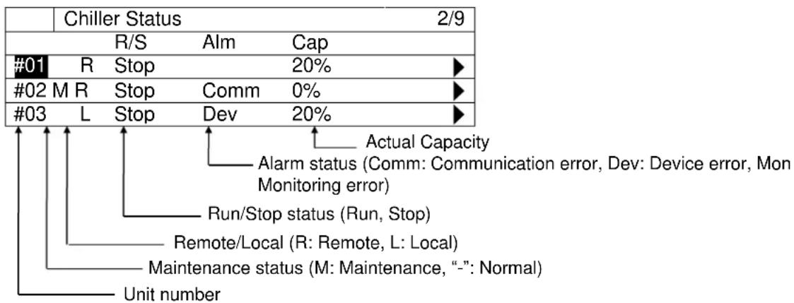
flowchart
graph TD
    A["Chiller Status 2/9"] --> B["R/S"]
    B --> C["Stop"]
    C --> D["Alm"]
    D --> E["Cap"]
    F["#01"] --> G["R"]
    G --> H["Stop"]
    H --> I["20%"]
    J["#02"] --> K["M R"]
    K --> L["Stop"]
    L --> M["Comm"]
    M --> N["0%"]
    O["#03"] --> P["L"]
    P --> Q["Stop"]
    Q --> R["Dev"]
    R --> S["20%"]
    T["Actual Capacity"] --> U["Alarm status (Comm: Communication error, Dev: Device error, Mon Monitoring error)"]
    T --> V["Run/Stop status (Run, Stop)"]
    T --> W["Remote/Local (R: Remote, L: Local)"]
    T --> X["Maintenance status (M: Maintenance, “-”: Normal)"]
    T --> Y["Unit number"]
12.2.2. Showing the detailed view of chillers
(Used screen: MainMenu > Status > Chillers > Detail)
- On the "MainMenu > Status > Chiller Status" screen, turn the click-dial Ⓞ to select the chiller unit you would like to see the detailed view then press down on the click-dial Ⓡ to jump to "ChillerXX detail" screen
| Chiller Status | 2/9 | ||||
| R/S | Alm | Cap | |||
| #01 | R | Stop | 20% | ▶ | |
| #02 | M R | Stop | Comm | 0% | ▶ |
| #03 | L | Stop | Dev | 20% | ▶ |
- On the "Chiller XX Detail" screen, detailed status of chiller can be monitored
| Chiller XX Detail | 1/14 | |
| Run/Stop | Stop | |
| -Command | - | |
| Alarm | CommError | |
| -ErrorCode | -- | |
| -AlarmReset | - | |
| Maintenance | - | |
| -State | - | |
| -Reason | - | |
| ActualCapacity | 50% | |
| Remote/Local | Remote | |
| ChWtEntTemp | 7.0°C | |
| ChWtLvgTemp | 12.0°C | |
| ChWtLvgTempSetpt | 7.0°C | |
| OpMode | Cooling | |
← Run/Stop State (Run, Stop)
← Run/Stop Command (Run, Stop)
← Alarm Status
← Alarm code of chiller (in hexadecimal)
← Alarm Reset Command (-, Reset)
← Maintenance setting (-, Maintenance)
← Maintenance state (-, Maintenance)
← Reason for maintenance state
← Actual Capacity
← Remote/Local state of chiller (Remote, Local)
← Chilled Water Entering Temperature
← Chilled Water Leaving Temperature
← Chilled Water Setpoint
← Operation Mode (Cooling, Heating)
12.3. Showing Current Status of Evaporator Side Shut Off Valve
(Used screen: MainMenu > Status > EvShutOffValve)
- On the "EvShutOffValve Status" screen, statuses of valves are displayed.
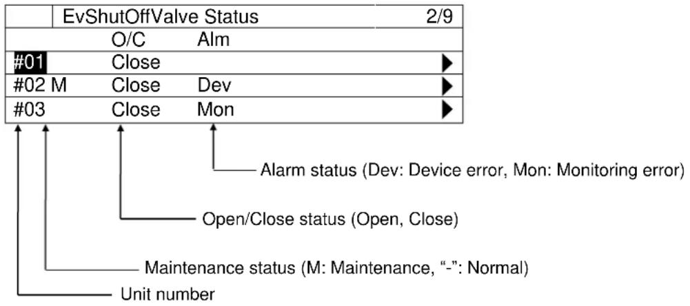
flowchart
graph TD
    A["EvShutOffValve Status 2/9"] --> B["O/C Alm"]
    B --> C["#01 Close"]
    C --> D["#02 M Close Dev"]
    D --> E["#03 Close Mon"]
    E --> F["Alarm status (Dev: Device error, Mon: Monitoring error)"]
    F --> G["Open/Close status (Open, Close)"]
    G --> H["Maintenance status (M: Maintenance, “-”: Normal)"]
    H --> I["Unit number"]
12.3.1. Showing the detailed view of Evaporator Side Shut Off Valve
- On the "MainMenu > Status > EvShutOffValve Status" screen, turn the click-dial to select the valve unit you would like to see the detailed view then press down on the click-dial to jump to "EvSO_ValveXX detail" screen
| EvShutOffValve Status | 2/9 | ||
| O/C | Alm | ||
| #01 | Close | ▶ | |
| #02 M | Close | Dev | ▶ |
| #03 | Close | Mon | ▶ |
- On the "EvSO_Valve XX Detail" screen, detailed status of Evaporator Side Shut Off Valve can be monitored
| EvSO_Valve XX Detail | XX/5 | |
| Open/Close | Close | |
| -Command | - | |
| Alarm | CommError | |
| Maintenance | - | |
| -State | - | |
← Open/Close State (Open/Close)
← Open/Close Command (Open/Close)
← Alarm Status
← Maintenance setting (-, Maintenance)
← Maintenance state (-, Maintenance)
12.4. Showing Current Status of Condenser Side Shut Off Valve
(Used screen: MainMenu > Status > CndShutOffValve)
- On the "EvShutOffValve Status" screen, statuses of valves are displayed.
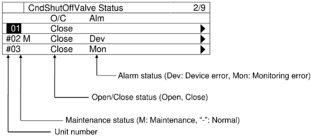
flowchart
graph TD
    A["CndShutOffValve Status 2/9"] --> B["01"]
    B --> C["Close"]
    C --> D["#02 M"]
    D --> E["Close"]
    E --> F["Dev"]
    F --> G["#03"]
    G --> H["Close"]
    H --> I["Mon"]
    I --> J["Alarm status (Dev: Device error, Mon: Monitoring error)"]
    J --> K["Open/Close status (Open, Close)"]
    K --> L["Maintenance status (M: Maintenance, “-”: Normal)"]
    L --> M["Unit number"]
12.4.1. Showing the detailed view of Condenser Side Shut Off Valve
- On the "MainMenu > Status > CndShutOffValve Status" screen, turn the click-dial to select the valve unit you would like to see the detailed view then press down on the click-dial to jump to "CndSO_ValveXX detail" screen
| CndShutOffValve Status | 2/9 | ||
| O/C | Alm | ||
| 01 | Close | ▶ | |
| #02 M | Close | Dev | ▶ |
| #03 | Close | Mon | ▶ |
- On the "CndSO_ValveXX Detail" screen, detailed status of Condenser Side Shut Off Valve can be monitored
| CndSO_ValveXX Detail | XX/5 | |
| Open/Close | Close | |
| -Command | - | |
| Alarm | CommError | |
| Maintenance | - | |
| -State | - | |
← Open/Close State (Open/Close)
← Open/Close Command (Open/Close)
← Alarm Status
← Maintenance setting (-, Maintenance)
← Maintenance state (-, Maintenance)
12.5. Showing Current Status of Primary Pumps
(Used screen: MainMenu > Status > PrimaryPump)
- On the "PrimaryPump Status" screen, statuses of pumps are displayed.
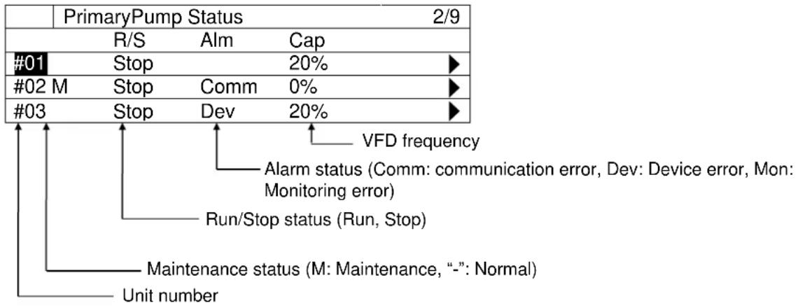
other
| PrimaryPump Status | 2/9 | |---|---| | R/S | Alm Cap | | #01 Stop | 20% ▶ | | #02 M Stop | Comm 0% ▶ | | #03 Stop | Dev 20% ▶ | VFD frequency Alarm status (Comm: communication error, Dev: Device error, Mon: Monitoring error) Run/Stop status (Run, Stop) Maintenance status (M: Maintenance, “-”: Normal) Unit number12.5.1. Showing the detailed view of Primary Pumps
- On the "MainMenu > Status > PrimaryPump Status" screen, turn the click-dial to select the primary pump unit you would like to see the detailed view then press down on the click-dial to jump to "PrimaryPumpXX detail" screen
| PrimaryPump Status | 2/9 | |||
| R/S | Alm | Cap | ||
| #01 | Stop | 20% | ▶ | |
| #02 M | Stop | Comm | 0% | ▶ |
| #03 | Stop | Dev | 20% | ▶ |
- On the "PrimaryPumpXX Detail" screen, detailed status of pump can be monitored
| PrimaryPumpXX Detail | 1/6 | |
| Run/Stop | Stop | |
| -Command | - | |
| Alarm | CommError | |
| Maintenance | - | |
| -State | - | |
| ActualCapacity | 50% | |
← Run/Stop State (Run, Stop)
← Run/Stop Command (Run, Stop)
← Alarm Status
← Maintenance setting (-, Maintenance)
← Maintenance state (-, Maintenance)
← Actual Capacity
12.6. Showing Current Status of Bypass Valve
(Used screen: MainMenu > Status > Bypass Valve)
- On the "BypassValve Status" screen, statuses of bypass valve is displayed.
| BypassValve Status | 1/1 | |
| ActualOpenRate | 20% | |
12.7. Showing Current Status of Condenser Pumps
(Used screen: MainMenu > Status > CondenserPump)
- On the "CondenserPump Status" screen, statuses of pumps are displayed.
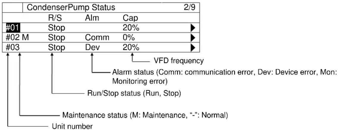
other
| Device | CondenserPump Status | VFD frequency | | :--- | :--- | :--- | | #01 | R/S Stop | 20% | | #02 M | Stop Comm | 0% | | #03 | Stop Dev | 20% |12.7.1. Showing the detailed view of Condenser Pumps
- On the "MainMenu > Status > CondenserPump Status" screen, turn the click-dial to select the condenser pump unit you would like to see the detailed view then press down on the click-dial to jump to "CondenserPumpXX detail" screen
| CondenserPump Status | 2/9 | |||
| R/S | Alm | Cap | ||
| #01 | Stop | 20% | ▶ | |
| #02 M | Stop | Comm | 0% | ▶ |
| #03 | Stop | Dev | 20% | ▶ |
- On the "CondenserPump XX Detail" screen, detailed status of pump can be monitored
| CondenserPump XX Detail | 1/6 | |
| Run/Stop | Stop | |
| -Command | - | |
| Alarm | CommError |
| Maintenance | - |
| -State | - |
| ActualCapacity | 50% |
← Alarm Status
← Maintenance setting (-, Maintenance)
← Maintenance state (-, Maintenance)
← Actual Capacity
12.8. Showing Current Status of Cooling Tower Bypass Valve
(Used screen: MainMenu > Status > CTBypassValve)
- On the "CTBypassValve Status" screen, statuses of cooling tower bypass valve are displayed.
| CTBypassValve Status | 1/1 | |
| #01ActualOpenRate | 20% | |
| #02ActualOpenRate | 20% | |
| #03ActualOpenRate | 20% | |
| #04ActualOpenRate | 20% | |
12.9. Showing Current Status of Sensors
(Used screen: MainMenu > Status > Sensors)
- On the "Sensors Status" screen, statuses of sensors are displayed. Displayed sensors differ depending on the system setup.
| Sensors Status | 1/32 | |
| DiffPress | 50kPa | |
| -Alarm | - | |
| ChWtLvgTemp | 6.6°C | |
| -Alarm | ||
| ChWtEntTemp | 11.7°C | |
| -Alarm | - | |
| CndWtEntTemp1 | -°C | |
| -Alarm | - | |
| CndWtLvgTemp1 | -°C | |
| -Alarm | - | |
| CndDiffPress1 | -kPa | |
| -Alarm | - | |
| CndWtEntTemp2 | -°C | |
| -Alarm | - | |
| CndWtLvgTemp2 | -°C | |
| -Alarm | - | |
| CndDiffPress2 | -kPa | |
| -Alarm | - | |
| CndWtEntTemp3 | -°C | |
| -Alarm | - | |
| CndWtLvgTemp3 | -°C | |
| -Alarm | - | |
| CndDiffPress3 | -kPa | |
| -Alarm | - | |
← Differential Pressure
← Alarm status for the sensor
← Supply Water Temperature
← Alarm status for the sensor
← Return Water Temperature
← Alarm status for the sensor
← Condenser Entering Water Temp. #1
← Alarm status for the sensor
← Condenser Leaving Water Temp. #1
← Alarm status for the sensor
← Condenser Differential Pressure #1
← Alarm status for the sensor
← Condenser Entering Water Temp. #2
← Alarm status for the sensor
← Condenser Leaving Water Temp. #2
← Alarm status for the sensor
← Condenser Differential Pressure #2
← Alarm status for the sensor
← Condenser Entering Water Temp. #3
← Alarm status for the sensor
← Condenser Leaving Water Temp. #3
← Alarm status for the sensor
← Condenser Differential Pressure #3
← Alarm status for the sensor
| CndWtEntTemp4 | -° C |
| -Alarm | - |
| CndWtLvgTemp4 | -° C |
| -Alarm | - |
| CndDiffPress4 | -kPa |
| -Alarm | - |
| OutdoorTemp | -° C |
| -Alarm |
← Condenser Entering Water Temp. #4
← Alarm status for the sensor
← Condenser Leaving Water Temp. #4
← Alarm status for the sensor
← Condenser Differential Pressure #4
← Alarm status for the sensor
← Outdoor Temperature
← Alarm status for the sensor
12.10. Showing Current Status of I/O
(Used screen: MainMenu > Status > I/O)
- On the "I/O Status" screen, status of I/Os are displayed.
| I/O Status | 1/1 | |
| DblSpt | OFF | |
12.11. Showing Current Status of Controls
(Used screen: MainMenu > Status > Control )
- On the "Control Status" screen, status of controls is displayed.
| Control Status | 1/2 | |
| Chiller | ▶ | |
| PrimaryPump | ▶ | |
← 12.11.1 Show current status of chiller control
← 12.11.2 Show current status of primary pump control
12.11.1. Show current status of chiller control
- From the "MainMenu>Status>Control Status" screen, turn the click-dial Ⓞ to select "Chiller" menu then press down on the click-dial Ⓞ to jump to "Chiller Control Status" screen.
| Control Status | 1/2 | |
| Chiller | ▶ | |
| PrimaryPump | ▶ | |
- On the "Chiller Control Status" screen, status of chiller controls is displayed.
| ChillerCtrl Status | 1/9 | |
| StageUp | ||
| -StgByLoadLimit | 100s | |
| -StgUpDiff | 100s | |
| -StgByTargetLoad | 100s | |
| -StgForRotation | 100s | |
| StageDown | ||
| -StgByLoadLimit | 100s | |
| -StgDnDiff | 100s | |
| -PonyChCtrl | 100s | |
← Timer count value for staging up for Load Condition
← Timer count value for staging up for Supply temperature condition
← Timer count value for staging up for Target load condition
← Timer count value for staging up for time without staging conditions
← Timer count value for staging down
← Timer count value for staging down
← Timer count value for staging down
12.11.2. Show current status of primary pump control
- From the "MainMenu>Status>Control Status" screen, turn the click-dial Ⓞ to select "PrimaryPump" menu then press down on the click-dial Ⓞ to jump to "PrimaryPump Control Status" screen.
| Control Status | 2/2 | |
| Chiller | ▶ | |
| PrimaryPump | ▶ | |
- On the "PrimaryPump Control Status" screen, status of primary pump controls is displayed.
| PriPpCtrl Status | 1/9 | |
| StageUp | 100s | |
| StageDown | 100s | |
← Timer count value for staging up
← Timer count value for staging down
13. Operation
Menu structure of related screens is displayed below.
□MainMenu
○ Status
- Command
Command
○ SystemRun/Stop
o TempSetpt
- EmgStopReset
○ ForcePriPumpMode
13.1. Basic Commanding
- Press the Home Button ☐ to show the "MainMenu" screen.
| MainMenu | 1/4 | |
| Status | ▶ | |
| Setting | ▶ | |
| ConfigMode | ▶ | |
| Password | ▶ | |
- On the "MainMenu" screen, turn the click-dial to select "Status" menu then press down on the click-dial to jump to "Status" screen.
| MainMenu | 1/4 | |
| Status | ▶ | |
| Setting | ▶ | |
| ConfigMode | ▶ | |
| Password | ▶ | |
- On the "Status" screen, turn the click-dial to select "Command" menu then press down on the click-dial to jump to "Command screen.
| Status | 1/22 | |
| Command | ▶ | |
| -Status | Standby | |
| -Alarm | - | |
| -FaultType | ---- | |
- On the "Command" screen, various commands can be sent.
| Command | 1/9 |
| SystemRun/Stop | Run | ← a. |
| -ActiveValue | Run | ← b. |
| TempSetpt | 7.0°C | ← c. |
| -ActiveValue | 7.0°C | ← d. |
| EmgStopReset | ← 13.2 Resetting emergency stop | |
| ForcePriPumpMode | OFF | ← e. |
| -ActiveValue | - | ← f. |
| ForceCndPumpMode | OFF | ← g. |
| -ActiveValue | - | ← h. |
Table 56 List of parameters which can be set from "Command" screen
| ID | Name | Definition |
| a. | SystemRun/Stop | Run/Stop command for iCM system |
| b. | -ActiveValue | Currently active command signal |
| c. | TempSetpt | Temperature setpoint command |
| d. | -ActiveValue | Currently active setpoint |
| e. | ForcePriPumpMode | ON/OFF command for force primary pump run |
| f. | -ActiveValue | Currently active command signal |
| g. | ForceCndPumpMode | ON/OFF command for force condenser pump run |
| h. | -ActiveValue | Currently active command signal |
13.2. Resetting emergency stop
(Used screen: "MainMenu > Status > Command > EmgStopReset")
- On the "MainMenu > Status > Command" screen, turn the click-dial to select "EmgStopReset" menu then press down on the click-dial to jump to "EmgStopReset" screen.
| Command | 5/9 | |
| -ActiveValue | Run | |
| TempSetpt | 7.0°C | |
| -ActiveValue | 7.0°C | |
| EmgStopReset | ▶ | |
- On the "EmgStopReset" screen you can reset emergency stop. In order to reset emergency stop state, emergency stop signal input from BACnet needs to be OFF.
| EmgStopReset | 1/3 | |
| EmgStopReset | - | |
| -Status | E-Stop | |
| -EmgStopFromBACnet | OFF | |
Table 57 List of parameters which can be set from "Command" screen
| ID | Name | Definition |
| a. | EmgStopReset | Reset command for emergency stop state |
| b. | -Status | Check if current status is emergency stop |
| c. | -EmgStopFromBACnet | Check current status of emergency stop command from BACnet |
13.3. Setting Chillers to "Maintenance"
Steps for setting chillers to “Maintenance” mode to exclude them from staging are described below.
- On the "MainMenu" screen, turn the click-dial to select "Status" menu then press down on the click-dial to jump to "Status" screen.
| MainMenu | 1/4 | |
| Status | ▶ | |
| Setting | ▶ | |
| ConfigMode | ▶ | |
| Password | ▶ | |
- On the "Status" screen, turn the click-dial to select "Chiller" menu then press down on the click-dial to jump to "Chiller Status" screen.
| Status | 13/22 | |
| Chiller | ▶ | |
| EvShutOffValve | ▶ | |
| CndShutOffValve | ▶ | |
| PrimaryPump | ▶ | |
- On the "Chiller status" screen, turn the click-dial to select the chiller you need to set to "Maintenance" mode then press down on the click-dial to jump to "ChillerXX Detail" screen.
| Chiller Status | 2/9 | ||||
| R/S | Alm | Cap | |||
| #01 | R | Stop | 20% | ▶ | |
| #02 | M | Stop | Comm | 0% | ▶ |
| #03 | L | Stop | Dev | 20% | ▶ |
- On the "ChillerXX Detail" screen, turn the click-dial ⏻ to select the "Maintenance" menu then press down on the click-dial ⏻ to jump to input mode screen for "Maintenance".
| ◆ | Chiller01 Detail | 5/12 |
| Maintenance | - | |
| -State | - | |
| ActualCapacity | 20% | |
| Remote/Local | Remote | |
- On the input mode screen for "Maintenance", turn the click-dial to change value ("-" for returning from Maintenance mode, or "Maintenance" to set the chiller to Maintenance mode) then press down on the click-dial to validate your setting.
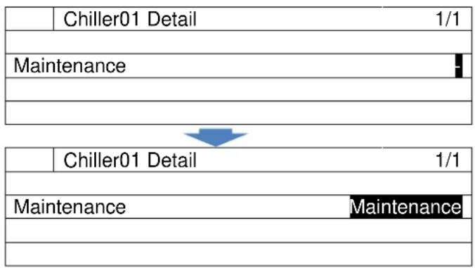
flowchart
graph TD
    A["Chiller01 Detail"] --> B["Maintenance"]
    B --> C["Chiller01 Detail"]
    C --> D["Maintenance"]
    D --> E["1/1"]
- On the "ChillerXX Detail" screen, look at "-State" menu below "Maintenance" to check if the setting has successfully been processed. Be careful when setting chillers back from Maintenance mode as when chiller is under alarm, they will be forced to be Maintenance mode and can't be set back.
| ◆ | Chiller01 Detail | 5/12 |
| Maintenance | Maintenance | |
| -State | Maintenance | |
| ActualCapacity | 20% | |
| Remote/Local | Remote | |
14. Alarming
14.1. Showing Current List of Alarms
Steps for showing the current list of alarms are described below.
- Press the Alarm button 🔒 to show the "Alarming" screen.
| Alarming | 1/3 | |
| AlarmList | 99 ▶ | |
| AlarmHistory | 99 ▶ | |
| -ClearHistory | - | |
- On the "Alarming" screen, turn the click-dial ⏻ to select "AlarmList" menu then press down on the click-dial ⏻ to jump to "AlarmList" screen.
| Alarming | 1/3 | |
| AlarmList | 99 ▶ | |
| AlarmHistory | 99 ▶ | |
| -ClearHistory | - | |
- On the "AlarmList" screen, current list of alarms are shown. Types of alarms that are displayed are: chiller alarms, pump alarms, and system alarms. Refer to the Appendix for alarm codes for each type.
| AlarmList | |
| +127: Chiller01 Device Error | |
| +998: Pump08 Monitoring Error | |
| +10111: Piping Gr#01 not enough pumps available to meet minimum | |
←Alarm Index of chiller is shown
- To see the details of individual alarms, simply select the alarm on the "AlarmList" screen by turning the click-dial ⏻ and jump to the "AlarmList Detail" screen by pressing down on the click-dial ⏻
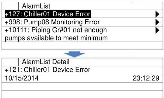
14.2. Showing History of Alarms
Steps for showing the history of alarms are described below.
- Press the Alarm button 🔒 to show the "Alarming" screen.
| Alarming | 1/3 |
| AlarmList | 99 ▶ |
| AlarmHistory | 99 ▶ |
| -ClearHistory | - |
- On the "Alarming" screen, turn the click-dial to select "AlarmHistory" menu then press down on the click-dial to jump to "AlarmHistory" screen.
| Alarming | 1/3 |
| AlarmList | 99 ▶ |
| AlarmHistory | 99 ▶ |
| -ClearHistory | - |
- On the "AlarmHistory" screen, history of alarms are shown
| AlarmHistory | |
| +127: Chiller01 Device Error | ▶ |
| -127: Chiller01 Device Error | ▶ |
| +10111: Piping Gr#01 not enough pumps available to meet minimum | ▶ |
← “+” sign indicates occurrence
← “-” sign indicates recovery
- To see the details of individual alarms, simply select the alarm on the "AlarmList" screen by turning the click-dial and jump to the "AlarmHistory Detail" screen by pressing down on the click-dial
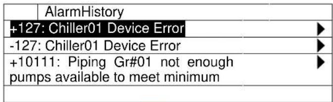
| AlarmHistory Detail | |
| +127: Chiller01 Device Error | |
| 10/15/2014 | 23:12:29 |
← Date and time of event is shown
14.3. Deleting History of Alarms
Steps for deleting the history of alarms are described below.
- Press the Alarm button 🔒 to show the "Alarming" screen.
| Alarming | 1/3 | |
| AlarmList | 99▶ | |
| AlarmHistory | 99▶ | |
| -ClearHistory | - | |
- On the "Alarming" screen, turn the click-dial Ⓞ to select "-ClearHistory" menu then press down on the click-dial Ⓞ to jump to input mode screen for "-ClearHistory"
| Alarming | 1/3 | |
| AlarmList | 99 | |
| AlarmHistory | 99 | |
| -ClearHistory | - | |
- On the input mode screen for "-ClearHistory", turn the click-dial to select "clear" then press down on the click-dial to validate your command.
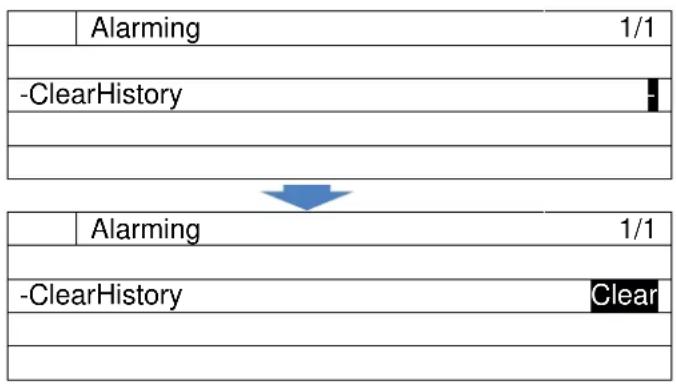
flowchart
graph TD
    A["Alarming"] --> B["-ClearHistory"]
    C["1/1"] --> D["1/1"]
    E["Alarming"] --> F["-ClearHistory"]
    G["1/1"] --> H["Clear"]
- History of alarms will be cleared.
| Alarming | 1/3 | |
| AlarmList | 99 ▶ | |
| AlarmHistory | 0 ▶ | |
| -ClearHistory | - | |
14.4. Resetting Alarms
Steps for resetting alarms on chillers are described below. Chillers have 3 kinds of errors; device error, communication error and monitoring error. Amog the 3 kinds of errors, device error (Alarm detected at the chiller) can be reset from iCM. Communication error and monitoring error can be reset by restoring communication status between iCM and chillers to match command from iCM and status of each device.
There are 2 steps for resetting alarms
A. Alarm Reset
B. Setting Chillers back from maintenance status
A. Alarm Reset
- Press the Home Button ☐ to show the "MainMenu" screen.
| MainMenu | 1 | |
| Status | ▶ | |
| Setting | ▶ | |
| ConfigMode | ▶ | |
| Password | ▶ | |
- On the "MainMenu" screen, turn the click-dial to select "Status" menu then press down on the click-dial to jump to "Status" screen.

| Status | ▶ |
| Setting | ▶ |
| ConfigMode | ▶ |
| Password | ▶ |
- On the "Status" screen, turn the click-dial Ⓞ to select "Chiller" menu then press down on the click-dial Ⓥ to jump to "Chiller Status" screen.
| Status | 11 | |
| Chiller | ||
| EvShutOffValve | ||
| CndShutOffValve | ||
| PrimaryPump | ||
- On the "Chiller status" screen, turn the click-dial Ⓞ to select the chiller you need to reset alarm then press down on the click-dial Ⓞ to jump to "ChillerXX Detail" screen.
| Chiller Status | 3 | ||||
| R/S | Alm | Cap | |||
| #01 | R | Stop | 20% | ▶ | |
| #02 | M R | Stop | Dev | 0% | ▶ |
| #03 | L | Stop | Comm | 20% | ▶ |
- On the "ChillerXX Detail" screen, turn the click-dial ⏻ to select the "Alarm reset" menu then press down on the click-dial ⏻ to jump to input mode screen for "Alarm reset".
| ▼ | Chiller01 Detail | 4 |
| Run/Stop | Stop | |
| Alarm | DevE | |
| -ErrorCode | E402 | |
| -AlarmReset | - | |
- On the input mode screen for "AlarmReset", turn the click-dial to change value to "Reset" then press down on the click-dial to validate your setting.
| Chiller01 Detail | 1 | |
| -AlarmReset | ||
| Chiller01 Detail | 1 | |
| -AlarmReset | Reset | |
- On the "ChillerXX Detail" screen, look at "Alarm" menu to check if the alarm has successfully been reset.
| ▼ | Chiller01 Detail | 4 |
| Run/Stop | Stop | |
| Alarm | - | |
| -ErrorCode | -- | |
| -AlarmReset | - | |
NOTE: While the conditions that triggered the alarm is true, you will not be able to reset the alarm.
15. APPENDIX – Alarms
15.1. Alarm Codes
15.1.1. Alarm for the chiller system
Alarm for the system includes hardware errors of the iCM itself or chiller system not being able to satisfy A/C load due to failure of multiple equipment.
The error code of chiller system alarm is described in a six-digits decimal alarm code e.g. 000101.
| Category 0 | Category 1 | Category2 | Alarm text | Alarm Code | Description | |
| Ext I/O Module Disconnect (01) | 101: Extension IO module#01 disconnect (ExtIO#01) | 000101 | Module Disconnected | |||
| 102: Extension IO module#02 disconnect (ExtIO#02) | 000102 | Module Disconnected | ||||
| 103: Extension IO module#03 disconnect (ExtIO#03) | 000103 | Module Disconnected | ||||
| 104: Extension IO module#04 disconnect (ExtIO#04) | 000104 | Module Disconnected | ||||
| 105: Extension IO module#05 disconnect (ExtIO#05) | 000105 | Module Disconnected | ||||
| 106: Extension IO module#06 disconnect (ExtIO#06) | 000106 | Module Disconnected | ||||
| 109: Extension IO module#09 disconnect (ExtIO#09) | 000109 | Module Disconnected | ||||
| 110: Extension IO module#10 disconnect (ExtIO#10) | 000110 | Module Disconnected | ||||
| 111: Extension IO module#11 disconnect (ExtIO#11) | 000111 | Module Disconnected | ||||
| 112: Extension IO module#12 disconnect (ExtIO#12) | 000112 | Module Disconnected | ||||
| 113: Extension IO module#13 disconnect (ExtIO#13) | 000113 | Module Disconnected | ||||
| 114: Extension IO module#14 disconnect (ExtIO#14) | 000114 | Module Disconnected | ||||
| 115: Extension IO module#15 disconnect (ExtIO#15) | 000115 | Module Disconnected | ||||
| 116: Extension IO module#16 disconnect (ExtIO#16) | 000116 | Module Disconnected | ||||
| Comm Module Disconnect (02) | 202: BACnet module disconnect (BACnet) | 000202 | Module Disconnected | |||
| Loop (1) | Loop1 (01) | 10101: Emergency stop command On | 010101 | I/O fault | ||
| 10102: All pumps are under maintenance | 010102 | I/O fault | ||||
| 10103: 10103: All cond. Pumps are under maintenance | 010103 | I/O fault | ||||
| Loop1 (01) | Shortage of flow (1) | 10111: PipingGr#01 not enough pumps available to meet minimum | 010111 | Pump fault | ||
| 10112: PipingGr#02 not enough pumps available to meet minimum | 010112 | Pump fault | ||||
| 10113: PipingGr#03 not enough pumps available to meet minimum | 010113 | Pump fault | ||||
| 10114: PipingGr#04 not enough pumps available to meet minimum | 010114 | Pump fault | ||||
| Shortage of cooling water flow (2) | 10121: Cond. PipingGr#01 not enough pumps available to meet minimum | 010121 | Condenser pump fault | |||
| 10122: Cond. PipingGr#02 not enough pumps available to meet minimum | 010122 | Condenser pump fault | ||||
| 10123: Cond. PipingGr#03 not enough pumps available to meet minimum | 010123 | Condenser pump fault | ||||
| 10124: Cond. PipingGr#04 not enough pumps available to meet minimum | 010124 | Condenser pump fault | ||||
| Ai (2) | Main controller (00) | 20002: Leaving water temp. setpoint command port failure (Base X2) | 020002 | I/O fault | ||
| 20006: Leaving water temp. sensor failure (Base X6) | 020006 | I/O fault | ||||
| 20007: Entering water temp. sensor failure (Base X7) | 020007 | I/O fault | ||||
| 20008: Header differential pressure sensor failure (Base X8) | 020008 | I/O fault | ||||
| Ext9 (09) | 20901: Entering condenser water temp. sensor#01 failure (ExtIO#09 X1) | 020901 | I/O fault | |||
| 20902: Entering condenser water temp. sensor#02 failure (ExtIO#09 X2) | 020902 | I/O fault | ||||
| 20903: Leaving condenser water temp. sensor#01 failure (ExtIO#09 X3) | 020903 | I/O fault | ||||
| 20904: Leaving condenser water temp. sensor#02 failure (ExtIO#09 X4) | 020904 | I/O fault | ||||
| 20905: Condenser water differential pressure sensor#01 failure (ExtIO#09 X5) | 020905 | I/O fault | ||||
| 20906: Condenser water differential pressure sensor#02 failure (ExtIO#09 X6) | 020906 | I/O fault | ||||
| 20907: Outdoor temp. sensor failure (ExtIO#09 X7) | 020907 | I/O fault | ||||
| Ext10 (10) | 21001: Entering condenser water temp. sensor#03 failure(ExtIO#10 X1) | 021001 | I/O fault | |
| 21002: Entering condenser water temp. sensor#04 failure(ExtIO#10 X2) | 021002 | I/O fault | ||
| 21003: Leaving condenser water temp. sensor#03 failure(ExtIO#10 X3) | 021003 | I/O fault | ||
| 21004: Leaving condenser water temp. sensor#04 failure(ExtIO#10 X4) | 021004 | I/O fault | ||
| 21005: Condenser water differential pressure sensor#03failure (ExtIO#10 X5) | 021005 | I/O fault | ||
| 21006: Condenser water differential pressure sensor#04failure (ExtIO#10 X6) | 021006 | I/O fault | ||
| 21001: Entering condenser water temp. sensor#03 failure(ExtIO#10 X1) | 021001 | I/O fault | ||
| Di(3) | Main controller (00) | 30001: iCM Run/Stop command port failure (Base X1) | 030001 | I/O fault |
| 30003: Emergency stop command port failure (Base X3) | 030003 | I/O fault | ||
| 30005: Double setpoint command port failure (Base X5) | 030005 | I/O fault | ||
| 30011: Force primary pump on command port failure (BaseDI1) | 030011 | I/O fault | ||
| 30012: Force condenser pump on command port failure(Base DI2) | 030012 | I/O fault | ||
| Ext1 (01) | 30102: Pump#01 On/Off status port failure (ExtIO#01 X2) | 030102 | I/O fault | |
| 30103: Pump#01 Alarm status port failure (ExtIO#01 X3) | 030103 | I/O fault | ||
| 30105: Pump#02 On/Off status port failure (ExtIO#01 X5) | 030105 | I/O fault | ||
| 30106: Pump#02 Alarm status port failure (ExtIO#01 X6) | 030106 | I/O fault | ||
| Ext2 (02) | 30202: Pump#03 On/Off status port failure (ExtIO#02 X2) | 030202 | I/O fault | |
| 30203: Pump#03 Alarm status port failure (ExtIO#02 X3) | 030203 | I/O fault | ||
| 30205: Pump#04 On/Off status port failure (ExtIO#02 X5) | 030205 | I/O fault | ||
| 30206: Pump#04 Alarm status port failure (ExtIO#02 X6) | 030206 | I/O fault | ||
| Ext3 (03) | 30302: Pump#05 On/Off status port failure (ExtIO#03 X2) | 030302 | I/O fault | |
| 30303: Pump#05 Alarm status port failure (ExtIO#03 X3) | 030303 | I/O fault | ||
| 30305: Pump#06 On/Off status port failure (ExtIO#03 X5) | 030305 | I/O fault | ||
| 30306: Pump#06 Alarm status port failure (ExtIO#03 X6) | 030306 | I/O fault | ||
| Ext4 (04) | 30402: Pump#07 On/Off status port failure (ExtIO#04 X2) | 030402 | I/O fault | |
| 30403: Pump#07 Alarm status port failure (ExtIO#04 X3) | 030403 | I/O fault | ||
| 30405: Pump#08 On/Off status port failure (ExtIO#04 X5) | 030405 | I/O fault | ||
| 30406: Pump#08 Alarm status port failure (ExtIO#04 X6) | 030406 | I/O fault | ||
| Ext5 (05) | 30501: Shut off valve#01 Open/Close status port failure(ExtIO#05 X1) | 030501 | I/O fault | |
| 30502: Shut off valve#02 Open/Close status port failure(ExtIO#05 X2) | 030502 | I/O fault | ||
| 30503: Shut o valve#03 Open/Close status port failure(ExtIO#05 X3) | 030503 | I/O fault | ||
| 30504: Shut o valve#04 Open/Close status port failure(ExtIO#05 X4) | 030504 | I/O fault | ||
| 30505: Shut o valve#01 Alarm status port failure (ExtIO#05 X5) | 030505 | I/O fault | ||
| 30506: Shut o valve#02 Alarm status port failure (ExtIO#05 X6) | 030506 | I/O fault | ||
| 30507: Shut o valve#03 Alarm status port failure (ExtIO#05 X7) | 030507 | I/O fault | ||
| 30508: Shut o valve#04 Alarm status port failure (ExtIO#05 X8) | 030508 | I/O fault | ||
| Ext6 (06) | 30601: Shut off valve#05 Open/Close status port failure(ExtIO#06 X1) | 030601 | I/O fault | |
| 30602: Shut off valve#06 Open/Close status port failure(ExtIO#06 X2) | 030602 | I/O fault | ||
| 30603: Shut o valve#07 Open/Close status port failure(ExtIO#06 X3) | 030603 | I/O fault | ||
| 30604: Shut o valve#08 Open/Close status port failure(ExtIO#06 X4) | 030604 | I/O fault | ||
| 30605: Shut o valve#05 Alarm status port failure (ExtIO#06 X5) | 030605 | I/O fault | ||
| 30606: Shut o valve#06 Alarm status port failure (ExtIO#06 X6) | 030606 | I/O fault | ||
| 30607: Shut o valve#07 Alarm status port failure (ExtIO#06 X7) | 030607 | I/O fault | ||
| 30608: Shut o valve#08 Alarm status port failure (ExtIO#06 X8) | 030608 | I/O fault | ||
| Ext11 (11) | 31105: Cond. pump#01 On/Off status port failure (ExtIO#11 X5) | 031105 | I/O fault | |
| 31106: Cond. pump#02 On/O status port failure (ExtIO#11 X6) | 031106 | I/O fault | ||
| 31107: Cond. pump#01 Alarm status port failure (ExtIO#11 X7) | 031107 | I/O fault | ||
| 31108: Cond. pump#02 Alarm status port failure (ExtIO#11 X8) | 031108 | I/O fault | ||
| Ext12 (12) | 31205: Cond. pump#03 On/O status port failure (ExtIO#12 X5) | 031205 | I/O fault | |
| 31206: Cond. pump#04 On/Off status port failure (ExtIO#12 X6) | 031206 | I/O fault | ||
| 31207: Cond. pump#03 Alarm status port failure (ExtIO#12 X7) | 031207 | I/O fault | ||
| 31208: Cond. pump#04 Alarm status port failure (ExtIO#12 X8) | 031208 | I/O fault | ||
| Ext13 (13) | 31305: Cond. pump#05 On/Off status port failure (ExtIO#13 X5) | 031305 | I/O fault | |
| 31306: Cond. pump#06 On/Off status port failure (ExtIO#13 X6) | 031306 | I/O fault | ||
| 31307: Cond. pump#05 Alarm status port failure (ExtIO#13 X7) | 031307 | I/O fault | ||
| 31308: Cond. pump#06 Alarm status port failure (ExtIO#13 X8) | 031308 | I/O fault | ||
| Ext14 (14) | 31405: Cond. pump#07 On/Off status port failure (ExtIO#14 X5) | 031405 | I/O fault | |
| 31406: Cond. pump#08 On/O status port failure (ExtIO#14 X6) | 031406 | I/O fault | ||
| 31407: Cond. pump#07 Alarm status port failure (ExtIO#14 X7) | 031407 | I/O fault | ||
| 31408: Cond. pump#08 Alarm status port failure (ExtIO#14 X8) | 031408 | I/O fault | ||
| Ext15 (15) | 31501: Cond. shut o valve#01 Open/Close status port failure (ExtIO#15 X1) | 031501 | I/O fault | |
| 31502: Cond. shut o valve#02 Open/Close status port failure (ExtIO#15 X2) | 031502 | I/O fault | ||
| 31503: Cond. shut o valve#03 Open/Close status port failure (ExtIO#15 X3) | 031503 | I/O fault | ||
| 31504: Cond. shut o valve#04 Open/Close status port failure (ExtIO#15 X4) | 031504 | I/O fault | ||
| 31505: Cond. shut o valve#01 Alarm status port failure (ExtIO#15 X5) | 031505 | I/O fault | ||
| 31502: Cond. shut o valve#02 Alarm status port failure (ExtIO#15 X6) | 031506 | I/O fault | ||
| 31503: Cond. shut o valve#03 Alarm status port failure (ExtIO#15 X7) | 031507 | I/O fault | ||
| 31504: Cond. shut o valve#04 Alarm status port failure (ExtIO#15 X8) | 031508 | I/O fault | ||
| Ext16 (16) | 31601: Cond. shut o valve#05 Open/Close status port failure (ExtIO#16 X1) | 031601 | I/O fault | |
| 31602: Cond. shut o valve#06 Open/Close status port failure (ExtIO#16 X2) | 031602 | I/O fault | ||
| 31603: Cond. shut o valve#07 Open/Close status port failure (ExtIO#16 X3) | 031603 | I/O fault | ||
| 31604: Cond. shut o valve#08 Open/Close status port failure (ExtIO#16 X4) | 031604 | I/O fault | ||
| 31605: Cond. shut o valve#05 Alarm status port failure (ExtIO#16 X5) | 031605 | I/O fault | ||
| 31602: Cond. shut o valve#06 Alarm status port failure (ExtIO#16 X6) | 031606 | I/O fault | ||
| 31603: Cond. shut o valve#07 Alarm status port failure (ExtIO#16 X7) | 031607 | I/O fault | ||
| 31604: Cond. shut o valve#08 Alarm status port failure (ExtIO#16 X8) | 031608 | I/O fault | ||
| Ao(4) | Main controller (00) | 40004: Byp. valve Open Rate command port failure (Base X4) | 040004 | I/O fault |
| Ext1 (01) | 40101: Pump#01 VFD command port failure (ExtIO#01 X1) | 040101 | I/O fault | |
| 40104: Pump#02 VFD command port failure (ExtIO#01 X4) | 040104 | I/O fault | ||
| Ext2 (02) | 40201: Pump#03 VFD command port failure (ExtIO#02 X1) | 040201 | I/O fault | |
| 40204: Pump#04 VFD command port failure (ExtIO#02 X4) | 040204 | I/O fault | ||
| Ext3 (03) | 40301: Pump#05 VFD command port failure (ExtIO#03 X1) | 040301 | I/O fault | |
| 40304: Pump#06 VFD command port failure (ExtIO#03 X4) | 040304 | I/O fault | ||
| Ext4 (04) | 40401: Pump#07 VFD command port failure (ExtIO#04 X1) | 040401 | I/O fault | |
| 40404: Pump#08 VFD command port failure (ExtIO#04 X4) | 040404 | I/O fault | ||
| Ext11 (11) | 41101: Cond. Pump#01 VFD command port failure (ExtIO#11 X1) | 041101 | I/O fault | |
| 41102: Cond. Pump#02 VFD command port failure (ExtIO#11 X2) | 041102 | I/O fault | ||
| 41103: Cond. Byp. valve#01 Open Rate command port failure (ExtIO#11 X3) | 041103 | I/O fault | ||
| 41104: Cond. Byp. valve#02 Open Rate command port failure (ExtIO#11 X4) | 041104 | I/O fault | ||
| Ext12 (12) | 41201: Cond. Pump#03 VFD command port failure (ExtIO#12 X1) | 041201 | I/O fault | |
| 41202: Cond. Pump#04 VFD command port failure (ExtIO#12 X2) | 041202 | I/O fault | ||
| 41203: Cond. Byp. valve#03 Open Rate command port failure (ExtIO#12 X3) | 041203 | I/O fault | ||
| 41204: Cond. Byp. valve#04 Open Rate command port failure (ExtIO#12 X4) | 041204 | I/O fault | ||
| Ext13 (13) | 41301: Cond. Pump#05 VFD command port failure (ExtIO#13 X1) | 041301 | I/O fault | |
| 41302: Cond. Pump#06 VFD command port failure (ExtIO#13 X2) | 041302 | I/O fault | ||
| Ext14 (14) | 41401: Cond. Pump#07 VFD command port failure (ExtIO#14 X1) | 041401 | I/O fault |
| 41402: Cond. Pump#08 VFD command port failure (ExtIO#14 X2) | 041402 | I/O fault | |||
| Do(5) | Main Controller(00) | 50021: iCM Run/Stop status port failure (Base DO1) | 050021 | I/O fault | |
| 50022: iCM Alarm status port failure (Base DO2) | 050022 | I/O fault |
15.1.2. Alarms for individual equipment
Alarm for individual equipment, chillers, pumps, valves, cooling towers and sensors, is displayed in the HMI. For each type of equipment, types of errors that are displayed include all or part of the following.
□ Communication error:
Communication with the equipment is lost
□ Device error :
Alarm signal from the equipment is received.
□ Monitoring error:
The equipment did not follow a command from iCM
□ Warning:
Warning signal from the equipment is received
Types of alarms that are displayed for each equipment type and their corresponding error codes are shown in the following table.
| Chiller | Shut off valve | Pump (I/O) | Bypass valve | Condenser pump | CT shutoff valve | ||
| Modbus | I/O | ||||||
| Communication error | Error code: 999 | N/A | N/A | N/A | N/A | N/A | N/A |
| Device error | Error code: Received from chiller | Error code: 997 | Error code: 997 | Error code: 997 | N/A | Error code: 997 | Error code: 997 |
| Monitoring error | Error code: 998 | Error code: 998 | Error code: 998 | Error code: 998 | N/A | Error code: 998 | Error code: 998 |
| Warning | Error code: Received from chiller | N/A | N/A | N/A | N/A | N/A | N/A |
- APPENDIX – BACnet Integration Data (Main Controller)
| Category | Name | Obj Type | Description | ||
| System | Monitoring | Alarm | iCM system alarm | BI | General alarm |
| iCM system alarm code | AI | iCM System Alarm List code | |||
| Status | iCM system status | MI | iCM Status Global | ||
| iCM system ON/OFF status | BI | iCM Syson | |||
| iCM system setpoint | AI | Active cold setpoint | |||
| iCM system load | AI | System load | |||
| Source of input status for ON/OFF | MI | Loc/remote mode of iCM Network on/off | |||
| Source of input status for chilled water temperature setpoint | MI | Loc/remote mode of iCM Cold setpoint | |||
| Source of input status for force primary pump on | MI | Loc/remote mode of iCM ChW pump force on | |||
| Status of double setpoint signal | BI | Double setpoint digital input | |||
| Differential pressure | AI | Chilled water loop pressure difference | |||
| Chilled water leaving temperature | AI | Chilled water leaving temperature before header | |||
| Chilled water return temperature | AI | Chilled water return temperature before header | |||
| Command | iCM system ON/OFF command | BO | iCM Network on/off | ||
| iCM chilled water temperature setpoint | AV | iCM Cold setpoint | |||
| Force primary pump on | BO | iCM Force Chilled water pump ON | |||
| Emergency stop | BO | iCM Emergency stop | |||
| Emergency stop reset | BV | iCM Emergency stop reset | |||
| Chiller | Monitoring | Alarm | Alarm status | BI | Active Unit Alarm Ch |
| Alarm code | AI | Alarm Code Ch | |||
| Alarm reset | BO | Clear Alarm Ch | |||
| Status | ON/OFF status | BI | Chiller On/Off | ||
| Actual capacity | AI | Load unit | |||
| Chilled water return temperature | AI | Chilled water return temperature unit | |||
| Chilled water leaving temperature | AI | Chilled water leaving temperature unit | |||
| Pump | Monitoring | Alarm | Alarm status | BI | Chilled water pump Alarm |
| Status | ON/OFF status | BI | Chilled water Pump On/Off | ||
| VFD capacity status | AI | Chilled water Pump VFD output | |||
| Bypass Valve | Monitoring | Status | Open rate status | AI | Load bypass valve position |
| Shut-off Valve | Monitoring | Alarm | Alarm status | BI | Shut-off valve Alarm |
| Status | Open/Close status | BI | Shut-off valve Open/Close | ||
17. APPENDIX – HMI Monitoring and Command
Points available for reading and writing from HMI is described below
| Category | Name | Description | ||
| System | Monitoring | Alarm | iCM system alarm | General alarm |
| iCM system alarm code | iCM System Alarm List code | |||
| Status | iCM system status | iCM Status Global | ||
| iCM system ON/OFF status | iCM Sys On | |||
| iCM system setpoint | Active cold setpoint | |||
| iCM system load | System load | |||
| Differential pressure | Chilled water loop pressure difference | |||
| Chilled water leaving temperature | Chilled water leaving temperature before header | |||
| Chilled water return temperature | Chilled water return temperature before header | |||
| Stage up inhibit status | Stage up inhibit by pull-down rate control | |||
| Command | iCM system ON/OFF command | iCM Network on/off | ||
| iCM chilled water temperature setpoint | iCM Cold setpoint | |||
| Force primary pump on | iCM Force Chilled water pump ON | |||
| Emergency stop reset | iCM Emergency stop reset | |||
| Chiller | Monitoring | Alarm | Alarm status | Active Unit Alarm Ch |
| Alarm code | Alarm Code Ch | |||
| Alarm reset | Clear Alarm Ch | |||
| Status | ON/OFF status | ON/OFF status of each chiller | ||
| Operation mode | Operation mode of each chiller | |||
| Chilled water setpoint | Chilled water setpoint of each chiller | |||
| Actual capacity | Actual capacity of each chiller | |||
| Operation hours | Accumulated operation hours of each chiller | |||
| Remote/local status | Remote/local status of each chiller | |||
| Available status | Available status of each chiller | |||
| Chilled water return temperature | Chilled water return temperature unit | |||
| Chilled water leaving temperature | Chilled water leaving temperature unit | |||
| Shut-off Valve | Monitoring | Alarm | Alarm status | Alarm status of each shut off valve |
| Status | Open/Close status | Open/Close status of each shut off valve | ||
| Available status | Available status of each shut off valve | |||
| Primary Pump | Monitoring | Alarm | Alarm status | Alarm status of each primary pump |
| Status | ON/OFF status | ON/OFF status of each primary pump | ||
| VFD capacity | VFD output of each primary pump | |||
| Available status | Available status of each primary pump | |||
| Operation hours | Accumulated operation hour of each pri. pump | |||
| Command | ON/OFF command | ON/OFF command for each condenser pump | ||
| Capacity command | Capacity command for each condenser pump | |||
| Bypass Valve (Evaporator) | Capacity command | Capacity command for each condenser pump | Load bypass valve position | |
| Bypass Valve (Cooling) | Monitoring | Status | Bypass valve open rate | Load bypass valve position |
| Condenser pump | Monitoring | Alarm | Alarm status | Alarm status of each condenser pump |
| Status | ON/OFF status | ON/OFF status of each condenser pump | ||
| VFD capacity | VFD output of each condenser pump | |||
| Available status | Available status of each condenser pump | |||
| Operation hours | Accumulated operation hr. of each con. pump | |||
| Command | ON/OFF command | ON/OFF command for each condenser pump | ||
| Capacity command | Capacity command for each condenser pump | |||
| Condenser bypass valve | Monitoring | Status | Open rate status | Open rate of each condenser bypass valve |
| Command | Open rate command | Open rate command of each condenser bypass valve | ||
18. APPENDIX - I/O Mapping
The I/O mapping of the main controller and I/O modules are listed below.
Main Controller (POL687.70)
| I/O name | System related I/O's | I/O type | Specification |
| AI1 | Unused | Ai | |
| AI2 | Unused | Ai | |
| AI3 | Unused | Ai | |
| X1 | System ON/OFF command | Di | non-voltage a-contact input |
| X2 | Temperature setpoint | Ai | 4-20mA input |
| X3 | Forced stoppage input | Di | non-voltage b-contact input |
| X4 | Bypass Valve Open Command | Ao | 4 - 20mA output |
| X5 | Double Setpoint ON/OFF | Di | non-voltage a-contact input |
| X6 | Chilled Water Leaving Temperature | Ai | 4 - 20mA input |
| X7 | Chilled Water Entering Temperature | Ai | 4 - 20mA input |
| X8 | Differential Pressure | Ai | 4 - 20mA input |
| DO1 | System ON/OFF status | Do | non-voltage a-contact output |
| DO2 | System alarm | Do | non-voltage a-contact output |
| DO3 | Unused | Do | |
| DO4 | Unused | Do | |
| DO5 | Unused | Do | |
| DO6 | Unused | Do | |
| DO7 | Unused | Do | |
| DO8 | Unused | Do | |
| DO9 | Unused | Do | |
| DO10 | Unused | Do | |
| DI1 | Primary pump force operation | Di | non-voltage a-contact output |
| DI2 | Cooling water pump force operation | Di | non-voltage a-contact output |
| DI3 | Unused | Di | |
| DI4 | Unused | Di | |
| DI5 | Unused | Di | |
| DI6 | Unused | Di |
I/O module #1 (POL965)
| I/O name | Primary pumps 1 and 2 | I/O type | Specification |
| X1 | Pri. pump1 VFD command | Ao | 4 - 20mA input |
| X2 | Pri. pump1 ON/OFF status | Di | non-voltage a-contact input |
| X3 | Pri. pump1 alarm | Di | non-voltage a-contact input |
| X4 | Pri. pump2 VFD command | Ao | 4 - 20mA input |
| X5 | Pri. pump2 ON/OFF status | Di | non-voltage a-contact input |
| X6 | Pri. pump2 alarm | Di | non-voltage a-contact input |
| X7 | Unused | Do | |
| X8 | Unused | Do | |
| DO1 | Pri. pump1 ON/OFF command | Do | non-voltage a-contact output |
| DO2 | Pri. pump2 ON/OFF command | Do | non-voltage a-contact output |
| DO3 | Unused | Do | |
| DO4 | Unused | Do | |
| DO5 | Unused | Do | |
| DO6 | Unused | Do | |
| DI1 | Unused | Di |
I/O module #2 (POL965)
| I/O name | Primary pumps 3 and 4 | I/O type | Specification |
| X1 | Pri. pump3 VFD command | Ao | 4 - 20mA input |
| X2 | Pri. pump3 ON/OFF status | Di | non-voltage a-contact input |
| X3 | Pri. pump3 alarm | Di | non-voltage a-contact input |
| X4 | Pri. pump4 VFD command | Ao | 4 - 20mA input |
| X5 | Pri. pump4 ON/OFF status | Di | non-voltage a-contact input |
| X6 | Pri. pump4 alarm | Di | non-voltage a-contact input |
| X7 | Unused | Do | |
| X8 | Unused | Do | |
| DO1 | Pri. pump3 ON/OFF command | Do | non-voltage a-contact output |
| DO2 | Pri. pump4 ON/OFF command | Do | non-voltage a-contact output |
| DO3 | Unused | Do | |
| DO4 | Unused | Do | |
| DO5 | Unused | Do | |
| DO6 | Unused | Do | |
| DI1 | Unused | Di |
I/O module #3 (POL965)
| I/O name | Primary pumps 5 and 6 | I/O type | Specification |
| X1 | Pri. pump5 VFD command | Ao | 4 - 20mA input |
| X2 | Pri. pump5 ON/OFF status | Di | non-voltage a-contact input |
| X3 | Pri. pump5 alarm | Di | non-voltage a-contact input |
| X4 | Pri. pump6 VFD command | Ao | 4 - 20mA input |
| X5 | Pri. pump6 ON/OFF status | Di | non-voltage a-contact input |
| X6 | Pri. pump6 alarm | Di | non-voltage a-contact input |
| X7 | Unused | Do | |
| X8 | Unused | Do | |
| DO1 | Pri. pump5 ON/OFF command | Do | non-voltage a-contact output |
| DO2 | Pri. pump6 ON/OFF command | Do | non-voltage a-contact output |
| DO3 | Unused | Do | |
| DO4 | Unused | Do | |
| DO5 | Unused | Do | |
| DO6 | Unused | Do | |
| DI1 | Unused | Di |
I/O module #4 (POL965)
| I/O name | Primary pumps 7 and 8 | I/O type | Specification |
| X1 | Pri. pump7 VFD command | Ao | 4 - 20mA input |
| X2 | Pri. pump7 ON/OFF status | Di | non-voltage a-contact input |
| X3 | Pri. pump7 alarm | Di | non-voltage a-contact input |
| X4 | Pri. pump8 VFD command | Ao | 4 - 20mA input |
| X5 | Pri. pump8 ON/OFF status | Di | non-voltage a-contact input |
| X6 | Pri. pump8 alarm | Di | non-voltage a-contact input |
| X7 | Unused | Do | |
| X8 | Unused | Do | |
| DO1 | Pri. pump7 ON/OFF command | Do | non-voltage a-contact output |
| DO2 | Pri. pump8 ON/OFF command | Do | non-voltage a-contact output |
| DO3 | Unused | Do | |
| DO4 | Unused | Do | |
| DO5 | Unused | Do | |
| DO6 | Unused | Do | |
| DI1 | Unused | Di |
I/O module #5 (POL965)
| I/O name | Evaporator Shut-off valves 1, 2, 3 and 4 | I/O type | Specification |
| X1 | Shut-off valve1 Open/Close status | Di | non-voltage a-contact input |
| X2 | Shut-off valve2 Open/Close status | Di | non-voltage a-contact input |
| X3 | Shut-off valve3 Open/Close status | Di | non-voltage a-contact input |
| X4 | Shut-off valve4 Open/Close status | Di | non-voltage a-contact input |
| X5 | Shut-off valve1 alarm | Di | non-voltage a-contact input |
| X6 | Shut-off valve2 alarm | Di | non-voltage a-contact input |
| X7 | Shut-off valve3 alarm | Di | non-voltage a-contact input |
| X8 | Shut-off valve4 alarm | Di | non-voltage a-contact input |
| DO1 | Shut-off valve1 Open/Close command | Do | non-voltage a-contact output |
| DO2 | Shut-off valve2 Open/Close command | Do | non-voltage a-contact output |
| DO3 | Shut-off valve3 Open/Close command | Do | non-voltage a-contact output |
| DO4 | Shut-off valve4 Open/Close command | Do | non-voltage a-contact output |
| DO5 | Unused | Do | |
| DO6 | Unused | Do | |
| DI1 | Unused | Di |
I/O module #6 (POL965)
| I/O name | Evaporator Shut-off valves 5, 6, 7 and 8 | I/O type | Specification |
| X1 | Shut-off valve5 Open/Close status | Di | non-voltage a-contact input |
| X2 | Shut-off valve6 Open/Close status | Di | non-voltage a-contact input |
| X3 | Shut-off valve7 Open/Close status | Di | non-voltage a-contact input |
| X4 | Shut-off valve8 Open/Close status | Di | non-voltage a-contact input |
| X5 | Shut-off valve5 alarm | Di | non-voltage a-contact input |
| X6 | Shut-off valve6 alarm | Di | non-voltage a-contact input |
| X7 | Shut-off valve7 alarm | Di | non-voltage a-contact input |
| X8 | Shut-off valve8 alarm | Di | non-voltage a-contact input |
| DO1 | Shut-off valve5 Open/Close command | Do | non-voltage a-contact output |
| DO2 | Shut-off valve6 Open/Close command | Do | non-voltage a-contact output |
| DO3 | Shut-off valve7 Open/Close command | Do | non-voltage a-contact output |
| DO4 | Shut-off valve8 Open/Close command | Do | non-voltage a-contact output |
| DO5 | Unused | Do | |
| DO6 | Unused | Do | |
| DI1 | Unused | Di |
I/O module #9 (POL965)
| I/O name | Cooling water system 1 and 2 Temperature and differential pressure sensors | I/O type | Specification |
| X1 | Cooling water chiller entering temperature 1 | Ai | 4 - 20mA input / NTC 10K input |
| X2 | Cooling water chiller entering temperature 2 | Ai | 4 - 20mA input / NTC 10K input |
| X3 | Cooling water chiller leaving temperature 1 | Ai | 4 - 20mA input / NTC 10K input |
| X4 | Cooling water chiller leaving temperature 2 | Ai | 4 - 20mA input / NTC 10K input |
| X5 | Cooling water differential pressure 1 | Ai | 4 - 20mA input |
| X6 | Cooling water differential pressure 2 | Ai | 4 - 20mA input |
| X7 | Outdoor temperature | Ai | 4 - 20mA input / NTC 10K input |
| X8 | Unused | - | |
| DO1 | Unused | Do | |
| DO2 | Unused | Do | |
| DO3 | Unused | Do | |
| DO4 | Unused | Do | |
| DO5 | Unused | Do | |
| DO6 | Unused | Do | |
| DI1 | Unused | Di |
I/O module #10 (POL965)
| I/O name | Cooling water system 3 and 4Temperature and differential pressure sensors | I/O type | Specification |
| X1 | Cooling water chiller entering temperature 3 | Ai | 4 - 20mA input / NTC 10K input |
| X2 | Cooling water chiller entering temperature 4 | Ai | 4 - 20mA input / NTC 10K input |
| X3 | Cooling water chiller leaving temperature 3 | Ai | 4 - 20mA input / NTC 10K input |
| X4 | Cooling water chiller leaving temperature 4 | Ai | 4 - 20mA input / NTC 10K input |
| X5 | Cooling water differential pressure 3 | Ai | 4 - 20mA input |
| X6 | Cooling water differential pressure 4 | Ai | 4 - 20mA input |
| X7 | Unused | - | |
| X8 | Unused | - | |
| DO1 | Unused | Do | |
| DO2 | Unused | Do | |
| DO3 | Unused | Do | |
| DO4 | Unused | Do | |
| DO5 | Unused | Do | |
| DO6 | Unused | Do | |
| DI1 | Unused | Di |
I/O module #11 (POL965)
| I/O name | Cooling water pumps 1 and 2 | I/O type | Specification |
| X1 | Cooling water pump 1 capacity command | Ao | 4 - 20mA output |
| X2 | Cooling water pump 2 capacity command | Ao | 4 - 20mA output |
| X3 | Cooling water bypass valve 1 open rate command | Ao | 4 - 20mA output |
| X4 | Cooling water bypass valve 2 open rate command | Ao | 4 - 20mA output |
| X5 | Cooling water pump 1 on/off status | Di | non-voltage a-contact input |
| X6 | Cooling water pump 2 on/off status | Di | non-voltage a-contact input |
| X7 | Cooling water pump 1 fault status | Di | non-voltage a-contact input |
| X8 | Cooling water pump 2 fault status | Di | non-voltage a-contact input |
| DO1 | Cooling water pump 1 on/off command | Do | non-voltage a-contact output |
| DO2 | Cooling water pump 2 on/off command | Do | non-voltage a-contact output |
| DO3 | Unused | Do | |
| DO4 | Unused | Do | |
| DO5 | Unused | Do | |
| DO6 | Unused | Do | |
| DI1 | Unused | Di |
I/O module #12 (POL965)
| I/O name | Cooling water pumps 3 and 4 | I/O type | Specification |
| X1 | Cooling water pump 3 capacity command | Ao | 4 - 20mA output |
| X2 | Cooling water pump 4 capacity command | Ao | 4 - 20mA output |
| X3 | Cooling water bypass valve 3 open rate command | Ao | 4 - 20mA output |
| X4 | Cooling water bypass valve 4 open rate command | Ao | 4 - 20mA output |
| X5 | Cooling water pump 3 on/off status | Di | non-voltage a-contact input |
| X6 | Cooling water pump 4 on/off status | Di | non-voltage a-contact input |
| X7 | Cooling water pump 3 fault status | Di | non-voltage a-contact input |
| X8 | Cooling water pump 4 fault status | Di | non-voltage a-contact input |
| DO1 | Cooling water pump 3 on/off command | Do | non-voltage a-contact output |
| DO2 | Cooling water pump 4 on/off command | Do | non-voltage a-contact output |
| DO3 | Unused | Do | |
| DO4 | Unused | Do | |
| DO5 | Unused | Do | |
| DO6 | Unused | Do | |
| DI1 | Unused | Di |
I/O module #13 (POL965)
| I/O name | Cooling water pumps 5 and 6 | I/O type | Specification |
| X1 | Cooling water pump 5 capacity command | Ao | 4 - 20mA output |
| X2 | Cooling water pump 6 capacity command | Ao | 4 - 20mA output |
| X3 | Unused | - | |
| X4 | Unused | - | |
| X5 | Cooling water pump 5 on/off status | Di | non-voltage a-contact input |
| X6 | Cooling water pump 6 on/off status | Di | non-voltage a-contact input |
| X7 | Cooling water pump 5 fault status | Di | non-voltage a-contact input |
| X8 | Cooling water pump 6 fault status | Di | non-voltage a-contact input |
| DO1 | Cooling water pump 5 on/off command | Do | non-voltage a-contact output |
| DO2 | Cooling water pump 6 on/off command | Do | non-voltage a-contact output |
| DO3 | Unused | Do | |
| DO4 | Unused | Do | |
| DO5 | Unused | Do | |
| DO6 | Unused | Do | |
| DI1 | Unused | Di |
I/O module #14 (POL965)
| I/O name | Cooling water pumps 7 and 8 | I/O type | Specification |
| X1 | Cooling water pump 7 capacity command | Ao | 4 - 20mA output |
| X2 | Cooling water pump 8 capacity command | Ao | 4 - 20mA output |
| X3 | Unused | - | |
| X4 | Unused | - | |
| X5 | Cooling water pump 7 on/off status | Di | non-voltage a-contact input |
| X6 | Cooling water pump 8 on/off status | Di | non-voltage a-contact input |
| X7 | Cooling water pump 7 fault status | Di | non-voltage a-contact input |
| X8 | Cooling water pump 8 fault status | Di | non-voltage a-contact input |
| DO1 | Cooling water pump 7 on/off command | Do | non-voltage a-contact output |
| DO2 | Cooling water pump 8 on/off command | Do | non-voltage a-contact output |
| DO3 | Unused | Do | |
| DO4 | Unused | Do | |
| DO5 | Unused | Do | |
| DO6 | Unused | Do | |
| DI1 | Unused | Di |
I/O module #15 (POL965)
| I/O name | Condenser Shut-off valves 1, 2, 3 and 4 | I/O type | Specification |
| X1 | Cooling water side shut-off valve 1 open/close status | Di | non-voltage a-contact input |
| X2 | Cooling water side shut-off valve 2 open/close status | Di | non-voltage a-contact input |
| X3 | Cooling water side shut-off valve 3 open/close status | Di | non-voltage a-contact input |
| X4 | Cooling water side shut-off valve 4 open/close status | Di | non-voltage a-contact input |
| X5 | Cooling water side shut-off valve 1 fault | Di | non-voltage a-contact input |
| X6 | Cooling water side shut-off valve 2 fault | Di | non-voltage a-contact input |
| X7 | Cooling water side shut-off valve 3 fault | Di | non-voltage a-contact input |
| X8 | Cooling water side shut-off valve 4 fault | Di | non-voltage a-contact input |
| DO1 | Cooling water side shut-off valve 1 open/close command | Do | non-voltage a-contact output |
| DO2 | Cooling water side shut-off valve 2 open/close command | Do | non-voltage a-contact output |
| DO3 | Cooling water side shut-off valve 3 open/close command | Do | non-voltage a-contact output |
| DO4 | Cooling water side shut-off valve 4 open/close command | Do | non-voltage a-contact output |
| DO5 | Unused | Do | |
| DO6 | Unused | Do | |
| DI1 | Unused | Di |
I/O module #16 (POL965)
| I/O name | Condenser Shut-off valves 5, 6, 7 and 8 | I/O type | Specification |
| X1 | Cooling water side shut-off valve 5 open/close status | Di | non-voltage a-contact input |
| X2 | Cooling water side shut-off valve 6 open/close status | Di | non-voltage a-contact input |
| X3 | Cooling water side shut-off valve 7 open/close status | Di | non-voltage a-contact input |
| X4 | Cooling water side shut-off valve 8 open/close status | Di | non-voltage a-contact input |
| X5 | Cooling water side shut-off valve 5 fault | Di | non-voltage a-contact input |
| X6 | Cooling water side shut-off valve 6 fault | Di | non-voltage a-contact input |
| X7 | Cooling water side shut-off valve 7 fault | Di | non-voltage a-contact input |
| X8 | Cooling water side shut-off valve 8 fault | Di | non-voltage a-contact input |
| DO1 | Cooling water side shut-off valve 5 open/close command | Do | non-voltage a-contact output |
| DO2 | Cooling water side shut-off valve 6 open/close command | Do | non-voltage a-contact output |
| DO3 | Cooling water side shut-off valve 7 open/close command | Do | non-voltage a-contact output |
| DO4 | Cooling water side shut-off valve 8 open/close command | Do | non-voltage a-contact output |
| DO5 | Unused | Do | |
| DO6 | Unused | Do | |
| DI1 | Unused | Di |
19. APPENDIX – Compatibility List
List of Daikin chillers that can be connected and managed by iCM is as follow:
| Product Name | Product Code | Controller | Compatibility |
| AWS | EWAD_C | MT 3^1 | Y (*) |
| AWS INV | EWAD_CZ | MT 3 | Y (*) |
| AWS FC | EWAD_CF | MT 3 | Y (**) |
| TZ | EWAD_TZ | MT 3 | Y (*) |
| TZB | EWAD_TZB | MT 3 | Y (*) |
| McENERGY HPI | EWYD_BZ | MT 2^2 | N |
| McENERGY Mono | EWAD_E | MT 3 | Y (*) |
| McENERGY Dual | EWAD_D | MT 3 | Y (*) |
| WHS-E | EWWD_I | MT 3 | Y (*) |
| Ecoplus | EWWD_G | MT 3 | Y (*) |
| Prox Evo | EWWQ_B | MT 3 | Y |
| WHB | EWWD_J | MT 3 | Y (*) |
| PFS | EWWD_H | MT 3 | Y |
| VZ | EWWD_VZ | MT 3 | Y (*) |
| WCZ Mono | EWWQ_G | MT 3 | Y (*) |
| WCZ Dual | EWWQ_L | MT 3 | Y (*) |
| WCZ HPI | EWHQ_G | MT 3 | N |
| ACZ-C Mulple Scroll CO | EWAQ_E | MT 3 | Y |
| ACZ-H Mulple Scroll HP | EWYQ_F | MT 3 | N |
| AGZ-C Mulple Scroll CO | EWAQ_G | MT 3 | Y (*) |
| AGZ-H Mulple Scroll HP | EWYQ_G | MT 3 | N |
| WSC – Centrifugal Single | DWSC | MT 2 | Y |
| WDC – Centrifugal Dual | DWDC | MT 2 | Y |
| WMC – Centrifugal Magnec | DWMC | MT 2 | Y |
Table 58 – Compatibility List
(*): NOTE 1: iCM can manage chillers with Paral Heat Recovery opon, but cannot manage chillers with Total Heat Recovery opon.
(**): NOTE 2: iCM can manage chillers with Free-cooling opon, but the funcon itself is managed by chiller controller (not centralized).
20. APPENDIX – Integrated Modbus Points
The list of Modbus points integrated to iCM is listed below.
20.1. Global chillers
The list of status monitoring points for (formerly) McQuay global chillers are shown below.
| Register | Name | |
| Address | Bit | |
| 40002 | b0 | Chiller Enable Output |
| 40008 | b0 | Chiller On/Off |
| 40011 | - | Chiller Mode Output |
| 40013 | - | Actual Capacity(3) |
| 40012 | - | Active Setpoint |
| 40028 | - | Warming Alarm Index |
| 40029 | - | Problem Alarm Index |
| 40030 | - | Fault Alarm Index |
| 40031 | - | Warning Alarm Code |
| 40032 | - | Problem Alarm Code |
| 40033 | - | Fault Alarm Code |
| 40016 | - | Evaporator Entering Fluid Temperature (5) |
| 40017 | - | Evaporator Leaving Fluid Temperature (6) |
| 40001 | b0 | Chiller Local/Remote |
The list of control command points for (formerly) McQuay global chillers are shown below.
| Register | Name | |
| Address | Bit | |
| 40009 | b0 | Chiller Enable Setpoint |
| 40034 | - | Chiller Mode Setpoint – Network |
| 40035 | - | Cool Setpoint – Network |
| 40010 | b0 | Clear Alarms – Network |
| 40316 | b0 | Units |
20.2. U.S. Chillers
The list of status monitoring points for (formerly) McQuay U.S. chillers are shown below.
| Register | Name | |
| Address | Bit | |
| 3 | - | Chiller On Off |
| 3 | - | Chiller On/Off |
| 40148 | - | Chiller Mode Output |
| 40011 | - | Actual Capacity |
| 40003 | - | Active Setpoint |
| 40130 | b1~b9 | Warnings |
| 40131~40132 | b0~b15 | Problems |
| 40133~40144 | b5~b4 | Faults |
| 40130 | b1~b9 | Warning Alarm Code |
| 40131~40132 | b0~b15 | Problem Alarm Code |
| 40133~40144 | b5~b4 | Fault Alarm Code |
| 40130 | b1~b9 | Warning Alarm Index |
| 40131~40132 | b0~b15 | Problem Alarm Index |
| 40133~40144 | b5~b4 | Fault Alarm Index |
| 40005 | - | Evaporator Entering Water Temperature |
| 40007 | - | Evaporator Leaving Water Temperature for Unit |
| 6 | - | Chiller Local/Remote |
The list of control command points for (formerly) McQuay U.S. chillers are shown below.
| Register | Name | |
| Address | Bit | |
| 2 | - | Chiller Enable |
| 40146 | - | Chiller Mode Setpoint |
| 40002 | - | Cool Setpoint |
| 25 | - | Clear Alarms |
NOTE
NOTE
The present publication is drawn up by of information only and does not constitute an offer binding upon Daikin Applied Europe S.p.A.. Daikin Applied Europe S.p.A. has compiled the content of this publication to the best of its knowledge. No express or implied warranty is given for the completeness, accuracy, reliability or fitness for particular purpose of its content, and the products and services presented therein. Specification are subject to change without prior notice. Refer to the data communicated at the time of the order. Daikin Applied Europe S.p.A. explicitly rejects any liability for any direct or indirect damage, in the broadest sense, arising from or related to the use and/or interpretation of this publication. All content is copyrighted by Daikin Applied Europe S.p.A..
DAIKIN APPLIED EUROPE S.p.A.
- Intelligent Chiller Manager (iCM)
- Index
- Introduction
- Functional Overview of iCM
- System Topology
- Technical Overview
- Electrical Panel
- Controllers
- Main Controller
- BACnet Module (Optional)
- MODbus Module (Optional)
- I/O Modules
- I/O Mapping
- Networks
- Modbus® / RS485 (Chiller Network)
- BACnet
- Human Machine Interface (HMI)
- Built-in HMI
- Remote HMI
- Web HMI
- Temperature sensors
- Wireless Router
- Differential Pressure sensor (Optional)
- Electrical Installation
- General specifications
- Operator's responsibility
- Mechanical Installation
- Control Panel installation
- NOTE: dimension of the external door are shown in Table 2 Electrical panel technical data
- Temperature sensor installation
- Differential Pressure sensor installation
- Description of Operation
- Menu Structure
- □ Status
- Setting
- □ Config Mode
- \*Special menus
- Basic Parts and Operation
- LCD Panel Display
- Setting Address of Extension I/O Modules
- Password Protection
- Scenario of Interaction
- Workflow for Initial Configuration / Commissioning
- On Site
- Off Site
- Workflow for Monitoring
- Status Monitoring
- Alarm Monitoring
- Workflow for Operation
- Commanding
- Parameter Tuning
- Workflow for Maintenance
- Equipment Maintenance
- HVAC System Component Change
- Configuration
- □MainMenu
- Password Input
- Setting System to Config Mode
- System Configuration Setting
- □ SystemSetting
- Setting Unit
- Setting Current Time / Date
- Changing Network Setting of Main Controller
- Changing Network Setting of BACnet Module
- Changing Network Setting of Daikin On Site (DoS: Cloud Connection)
- Showing information of iCM
- Equipment Registration
- □ DeviceRegistration
- Chiller Registration
- PrimaryPump Registration
- CondenserPump Registration
- CTBypassValve Registration
- Sensors Registration
- ExtI/O Registration
- BACnet\_Module Registration
- Equipment Configuration
- □ DeviceConfig
- System Configuration
- Chiller Configuration
- Evaporator Shut Off Valve Configuration
- Condenser Shut Off Valve Configuration
- Primary Pump Configuration
- Condenser Pump Configuration
- NOTE: This menu displays, but hardware of models EKDICMPA\* does not support this function.
- Sensor Configuration
- Setting sensor conversion parameter when using mA type
- Setting sensor conversion parameter when using NTC10K type
- Equation 1 Steinhart-Hart Equation
- Modbus Communication Setting
- Ai Threshold Setting
- Equipment Control Setting
- □ DevcieCtrlParam
- Chiller Control Setting
- Setting sequence order when using fixed order sequencing
- Setting detailed options for staging up / down
- Setting full / low load for each chiller
- Primary Pump Control Setting
- Setting PI Parameters for Pump VFD Control
- Setting periodical pump staging for rotation
- Setting minimum / maximum number of operating pumps for each piping group
- Bypass Valve Control Setting
- Setting PI Parameters for Bypass Valve Control
- Condenser Pump Control Setting
- Setting DT\_PI Parameters for Pump VFD Control
- Setting DP\_PI Parameters for Pump VFD Control
- Setting minimum / maximum number of operating pumps for each piping group
- Cooling Tower Bypass Valve Control Setting
- Setting PI Parameters for Cooling Tower Bypass Valve Control
- System Control Setting
- □ SystemCtrlParam
- Power Failure Recovery
- Protect System
- Double Temperature Setpoint
- Pull Down Rate Control
- Setpoint reset
- Source of Input Setting
- CtrlModeSetting
- Trial Run
- TrialRun
- Chiller Trial Run
- I/O Trial Run
- Checking individual ports of base controller
- Checking individual ports of extension I/O #1
- Checking individual ports of extension I/O #5
- Checking individual ports of extension I/O #6
- Checking individual ports of extension I/O #9
- Checking individual ports of extension I/O #10
- Checking individual ports of extension I/O #11
- Checking individual ports of extension I/O #12
- Checking individual ports of extension I/O #13
- Checking individual ports of extension I/O #14
- Checking individual ports of extension I/O #15
- Checking individual ports of extension I/O #16
- BACnet Module Trial Run
- Saving / Loading Configuration Data
- □ Backup/Restore
- Monitoring
- Showing Current Status of System
- Showing Current Status of Chillers
- Showing the overview of chillers
- Showing the detailed view of chillers
- Showing Current Status of Evaporator Side Shut Off Valve
- Showing the detailed view of Evaporator Side Shut Off Valve
- Showing Current Status of Condenser Side Shut Off Valve
- Showing the detailed view of Condenser Side Shut Off Valve
- Showing Current Status of Primary Pumps
- Showing the detailed view of Primary Pumps
- Showing Current Status of Bypass Valve
- Showing Current Status of Condenser Pumps
- Showing the detailed view of Condenser Pumps
- Showing Current Status of Cooling Tower Bypass Valve
- Showing Current Status of Sensors
- Showing Current Status of I/O
- Showing Current Status of Controls
- Show current status of chiller control
- Show current status of primary pump control
- Operation
- Command
- Basic Commanding
- Resetting emergency stop
- Setting Chillers to "Maintenance"
- Alarming
- Showing Current List of Alarms
- Showing History of Alarms
- Deleting History of Alarms
- Resetting Alarms
- Alarm Reset
- APPENDIX – Alarms
- Alarm Codes
- Alarm for the chiller system
- Alarms for individual equipment
- APPENDIX – HMI Monitoring and Command
- APPENDIX - I/O Mapping
- APPENDIX – Compatibility List
- APPENDIX – Integrated Modbus Points
- Global chillers
- U.S. Chillers
- DAIKIN APPLIED EUROPE S.p.A.
Brand : DAIKIN
Model : EKDICMPAL
Category : Controller