
ADA4 - Audio converter AJA - Free user manual and instructions
Find the device manual for free ADA4 AJA in PDF.


| Product Type | 4-Channel Audio A/D and D/A Converter |
| Model | ADA4 |
| Dimensions | 5.8 x 3.1 x 1 inches (147 x 79 x 25 mm) |
| Weight | Approx. 0.5 lbs (0.23 kg) |
| Power Supply | AJA DWP-U-R1, 100-240V AC, 50/60Hz, +5V DC, 7.5W |
| Audio Conversion | 24-bit, 48/96 kHz sample rate |
| Analog Audio I/O | Balanced XLR, 1 channel per connector |
| Digital Audio I/O | Balanced 110 ohm XLR, 2 channels per connector |
| Reference Input | AES11, Wordclock, Tri-level Sync, or Color Black (75 ohm loop) |
| Sample Rate Conversion | 48 kHz to 96 kHz and vice versa |
| Modes of Operation | Normal (A/D, D/A, or both) and Synchronizer (D/D with reclocking) |
| Audio Level Settings | Selectable via DIP switches: +24 dBu, +18 dBu, +15 dBu, +10 dBV |
| User Controls | External DIP switches (4) and internal jumpers (3) |
| Included Accessories | XLR breakout cable and power supply |
| Compliance | FCC Class A, CE, ICES-003, KC, BSMI, VCCI |
| Safety | Designed for professional use; Class A device |
| Warranty | 5 years limited warranty |
| Maintenance | Clean with dry cloth; no user-serviceable parts inside |
| Repairability | Refer to qualified service personnel; opening chassis voids warranty |
Frequently Asked Questions - ADA4 AJA
User questions about ADA4 AJA
0 question about this device. Answer the ones you know or ask your own.
Ask a new question about this device
Download the instructions for your Audio converter in PDF format for free! Find your manual ADA4 - AJA and take your electronic device back in hand. On this page are published all the documents necessary for the use of your device. ADA4 by AJA.
USER MANUAL ADA4 AJA
4-Channel Audio A/D and D/A
Installation & Operation Guide
Version 1.0r2
Published: July 3, 2014

Table of Contents
Notices....3
Trademarks 3
Copyright.... 3
Contacting Support 3
Chapter 1: ADA4 Introduction....4
Overview.... 4
Features 4
ADA4 Simplified Block Diagrams.... 5
ADA4 I/O Connections.... 6
Lock LED....6
User Controls....8
Installation 8
Chapter 2: ADA4 Operation....9
Internal Jumpers 9
48 KHz/96KHz Output Mode (Jumper #1) 9
Normal/Synchronizer Mode (Jumper #2) 9
Jumper #3 9
DIP Switches 9
DIP Switch Settings 10
DIP Switches 3 & 4 (Audio Levels).... 10
Appendix A: Specifications .....11
Appendix B: Safety and Compliance....12
Federal Communications Commission (FCC) Compliance Notices 12
Class A Interference Statement 12
FCC Caution 12
Canadian ICES Statement.... 12
European Union and European Free Trade Association (EFTA)
Regulatory Compliance.... 13
Declaration of Conformity.... 13
Korean KCC Compliance Statement 14
Taiwan Compliance Statement 14
Japanese Compliance Statement 14
Recycling Notice 14
Translated Warning and Caution Messages.... 15
Before Operation Please Read These Instructions 15
Warranty Information....22
Limited Warranty.... 22
Trademarks
AJA® , Io® , Ki Pro® , KONA® , KUMO® , T-TAP® , Because it matters. and ROI® are registered trademarks of AJA Video Systems, Inc. in the United States. AJA and Ki Pro are trademarks of AJA Video Systems, Inc. registered in other countries. AJA Control Room™, CION™, Corvid Ultra™, FiDO™, Science of the Beautiful™, TruScale™, TruZoom™, V2Analog™ and V2Digital™ are trademarks of AJA Video Systems, Inc.
AirPort, Apple, Apple logo, AppleShare, AppleTalk, FireWire, iPod, iPod touch, Mac and Macintosh are registered trademarks of Apple Inc. FinalCut Pro, QuickTime and QuickTime logo are trademarks of Apple Inc.
Avid, Avid DNxHD and Media Composer are registered trademarks of Avid Technology, Inc.
HDMI, the HDMI logo and High-Definition Multimedia Interface are trademarks or registered trademarks of HDMI Licensing, LLC.
DVI is a registered trademark of DDWG.
TASCAM is a registered trademark of TEAC Corporation.
All other trademarks are the property of their respective holders.
Copyright
Copyright © 2014 AJA Video Systems, Inc. All rights reserved. All information in this manual is subject to change without notice. No part of the document may be reproduced or transmitted in any form, or by any means, electronic or mechanical, including photocopying or recording, without the express written permission of AJA Video Systems, Inc.
Contacting Support
When calling for support, have all information at hand prior to calling.
To contact AJA for sales or support, use any of the following methods:
Telephone: +1.530.271.3190
FAX:+1.530.271.3140
Web: http://www.aja.com
Support Email: support@aja.com
Sales Email: sales@aja.com
Chapter 1: ADA4 Introduction

Overview
The ADA4 is a 4 channel audio converter which can be configured as a 4 channel A/D, a 4 channel D/A, or 2 channel A/D and 2 channel D/A. The ADA4 can accept a AES11, wordclock, or video sync/color black reference input for synchronization. Reference input and synchronization is automatic. Audio levels are configurable via DIP switch control.
NOTE: The information in this manual is for ADA4 converters with Serial Number H43000 or Later.
Features
• Simultaneous A/D and D/A, or AES Synchronizer
• Full-time AES11 low jitter reference output
- Up to 4 channels of balanced analog to AES/EBU audio
- Up to 4 channels of AES/EBU to balanced analog audio
• Supplied XLR breakout cable
• AES11/Wordclock/Tri-level Sync/Color Black Reference Loop
- Adjustable Audio Levels
• Sample Rate Conversion Between 96KHz and 48KHz
• DIP switch configuration
- Uses universal input +5V power supply AJA model DWP-U-R1 (included)
Figure 1. ADA4, Normal Mode Block Diagram (Jumper 2 Installed), A/D or D/A

flowchart
graph TD
    A["Input A"] --> B["Audio A/D"]
    C["Input B"] --> D["Audio D/A"]
    E["Input C"] --> F["Audio A/D"]
    G["Input D"] --> H["Audio D/A"]
    I["Reference Loop"] --> J["Cock Gen"]
    K["Reference Loop"] --> J
    B --> L["Dipswitch 1"]
    D --> M["Dipswitch 2"]
    F --> N["Dipswitch 3"]
    H --> O["Dipswitch 4"]
    J --> P["AES-11 Out"]
    L --> Q["Output A"]
    M --> R["Output B"]
    N --> S["Output C"]
    O --> T["Output D"]
Figure 2. ADA4, Synchronizer Mode Block Diagram (Jumper 2 Removed), D/D

flowchart
graph TD
    A["Input A"] --> B["Audio DVD"]
    C["Input B"] --> B
    D["Input C"] --> E["Audio DVD"]
    F["Input D"] --> E
    B --> G["Output A"]
    E --> H["Output B"]
    I["Reference Loop"] --> J["Clock Get"]
    K["Reference Loop"] --> J
    J --> L["AES-11 Out"]
ADA4 I/O Connections
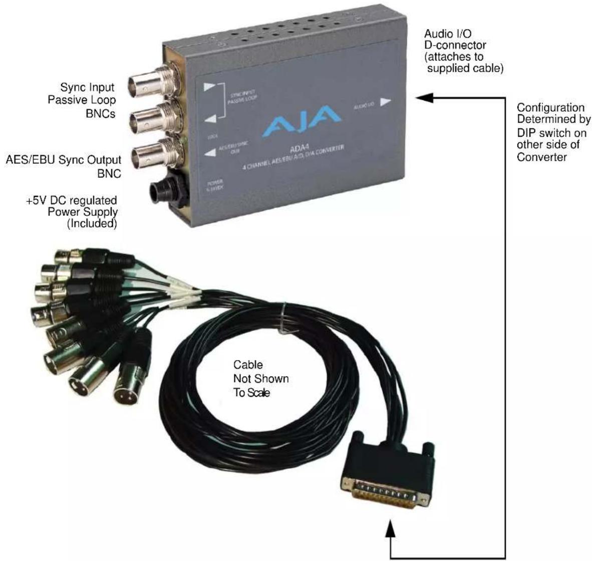
Lock LED
An LED is located next to the BNC connectors which shows the type of signal locked (if any). Here are the meanings of the LED colors:
- Red = HDlock
- Green = S D l o c k
- Amber = AES-11 lock or Word Clock lock
Figure 3. ADA4 XLR Breakout Cable Pinouts

flowchart
graph LR
    A["AJA Channel Index"] --> B["ADA4"]
    subgraph Inputs
        A1["Input A"] --> A2["Input B"]
        A3["Input C"] --> A4["Input D"]
        A5["Output A"] --> A6["Output B"]
        A7["Output B"] --> A8["Output C"]
        A9["Output D"] --> A10["Output D"]
    end
    subgraph Outputs
        A10["Input A"] --> A11["Input B"]
        A12["Input C"] --> A13["Input D"]
        A14["Output A"] --> A15["Output B"]
        A16["Output B"] --> A17["Output C"]
        A18["Output D"] --> A19["Output D"]
    end
User Controls
The user interface for the ADA4 is a 4-switch DIP accessible through a cut-out in the bottom of the unit, and an internal 3-position jumper block accessed by removing the ADA4 cover (secured by 4 screws). Use the jumper to configure the mode of operation (Normal or Synchronizer). Then use the DIP switches—if necessary—to configure channels and audio levels.
Factory default switch settings are Normal Mode (jumper installed) and all the DIP switches in the leftmost position. The exact function of the jumper settings and each DIP switch are described in "ADA4 Operation" on page 9.
Installation
Typically, ADA4 installation consists of the following:
- Disconnect +5VDC from the converter.
- If you wish to operate the ADA4 as a synchronizer, or with 96k outputs, open the case and set the internal jumpers as required.
- Configure the DIP switch for the desired equipment configuration, if necessary.
- Connect sync signals to the converter BNCs.
- Connect audio equipment using the provided breakout cable.
- Apply power to the converter.
Chapter 2: ADA4 Operation
Internal Jumpers
Jumpers inside the case determines whether the unit operates as an AD/DA audio converter (Normal mode, the default setting) or as a Synchronizer, and whether the ADA4 Mini-Converter's digital outputs are 48k (the default setting) or 96k.
NOTE: If you will be using the ADA4 as an A/D D/A converter with 48k outputs, no jumper changes are required. Configuration is accomplished using the external DIP switches.
To access the internal jumpers, remove the four Phillips screws securing the back side of the ADA4 case (the side having the DIP switch access hole in it). Once the case cover is removed, jumper positions 1 through 3 are clearly marked on the circuit board next to the jumper.
48 KHz/96KHz Output Mode (Jumper #1)
Jumper #1 selects the AES outputs and the AES11 reference output sample rates.
- When Jumper 1 is installed, they run at 48 KHz.
- When Jumper 1 is removed, they run at 96 KHz.
Normal/ Synchronizer Mode (Jumper #2)
Jumper #2 selects Normal or Synchronizer operating mode.
- When Jumper 2 is installed, the ADA4 runs in Normal node, and the ADA4 DIP switches are available for configuration.
- When Jumper 2 is removed, the ADA4 runs in Synchronizer mode. Synchronizer mode is an alternative operating mode where no audio A/D or D/A conversion takes place. Instead, it allows for an AES input to be sample rate converted and reclocked to reveal an AES output that is low jitter, and—when a reference signal is applied—locked to reference. Without a reference signal applied, the ADA4 reclocks the output based on its stable, free-running local oscillator. In this mode the DIP switches are ignored.
Jumper #3 Jumper #3 is currently unused.
Refer to the following diagram for jumper setting examples
Figure 4. ADA4, Internal Jumper Setting Examples.

Example 1
All Jumpers ON
Default Setting
Normal Mode
48k Outputs

Example 2
Jumper 1 OFF
96k Outputs

Example 3
Jumper 2 OFF
Synchronizer Mode
DIP Switches
When in Normal Mode, the DIP switches on the back of the unit are active and can be used to set channel pairs to be A/D or D/A converters, and to set audio levels.
Figure 5. ADA4 DIP Switches and Label

Factory default switch settings are all in the leftmost position.
DIP Switch Settings
The functions of the DIP switches and what they control are described in the following tables.
Table 1. DIP Switch Setting Descriptions
| SWITCH | FUNCTION | DIP Set LEFT (default) | DIP Set RIGHT |
| 1 Conversion for channels 1 and 2 | Select Analog to Digital Conversion (A/D). | Select Digital to Analog Conversion (D/A). | |
| 2 Conversion for channels 3 and 4 | Select Analog to Digital Conversion (A/D). | Select Digital to Analog Conversion (D/A). | |
| 3 & 4 Audio Levels | These two DIP switches (LEVEL 1, LEVEL 2) act together to set output levels. Zero (0) is Left position, one (1) is Right position. See Table 2 below for setting information. | ||
DIP Switches 3 & 4 (Audio Levels)
Professional audio equipment has much higher levels than consumer equipment: a 0 VU reading corresponds to +4 dBu. Connecting a professional +4 dBu device to a consumer audio input -10dBV (-7.8 dBu) may cause overloading, whereas the output of a consumer device probably does not have sufficient power to drive a professional audio input. With consumer and semi-professional audio equipment, a VU reading of 0 dB is typically referenced to -10 dBV. 0 dBu = 0.775 VRMS.
Appendix A: Specifications
Analog Audio I/O Balanced, XLR. One Channel per XLR connector.
AES Audio I/O Balanced 110 ohm, XLR. Two Channels per XLR connector.
Analog Audio Levels (with Respect to full scale digital, selectable by DIP switch)
• +24dBu (SMPTE RP155)
• +18dBu (EBU R68),
• +15dBu (Germany)
• +10dBV (consumer +12.2 dBu)
Audio Converters 24 bit, 48/96 KHz
User Controls External DIP switches (4)
Internal Jumpers (3)
Size 5.8" x 3.1" x 1 (147 x 79 x 25mm)
Power Uses AJA Power Supply model DWP-U-R1 (included)
100-240V, 50/60Hz Universal Input
+5V DC regulated, 7.5 watt capacity
Reference Loop 75 Ohm (unterminated). HD/SD Sync, AES-11, or Wordclock (48/96 KHz)
Appendix B: Safety and Compliance
Federal Communications Commission (FCC) Compliance Notices
Class A Interference Statement
This equipment has been tested and found to comply with the limits for a Class A digital device, pursuant to Part 15, Subpart B of the FCC Rules. These limits are designed to provide reasonable protection against harmful interference in a residential installation. This equipment generates, uses, and can radiate radio frequency energy and, if not installed and used in accordance with the instructions, may cause harmful interference to radio communications. However, there is no guarantee that interference will not occur in a particular installation. If this equipment does cause harmful interference to radio or television reception, which can be determined by turning the equipment off and on, the user is encouraged to try to correct the interference by one or more of the following measures:
- Reorient or relocate the receiving antenna.
- Increase the separation between the equipment and receiver.
- Connect the equipment into an outlet on a circuit different from that to which the receiver is connected.
- Consult the dealer or an experienced radio/TV technician for help.
FCC Caution
This device complies with Part 15 of the FCC Rules. Operation is subject to the following two conditions: (1) This device may not cause harmful interference, and (2) this device must accept any interference received, including interference that may cause undesired operation.
Canadian ICES Statement
Canadian Department of Communications Radio Interference Regulations
This digital apparatus does not exceed the Class A limits for radio-noise emissions from a digital apparatus as set out in the Radio Interference Regulations of the Canadian Department of Communications. This Class A digital apparatus complies with Canadian ICES-003.
European Union and European Free Trade Association (EFTA) Regulatory Compliance
This equipment may be operated in the countries that comprise the member countries of the European Union and the European Free Trade Association. These countries, listed in the following paragraph, are referred to as The European Community throughout this document:
AUSTRIA, BELGIUM, BULGARIA, CYPRUS, CZECH REPUBLIC, DENMARK, ESTONIA, FINLAND, FRANCE, GERMANY, GREECE, HUNGARY, IRELAND, ITALY, LATVIA, LITHUANIA, LUXEMBOURG, MALTA, NETHERLANDS, POLAND, PORTUGAL, ROMANIA, SLOVAKIA, SLOVENIA, SPAIN, SWEDEN, UNITED KINGDOM, ICELAND, LICHTENSTEIN, NORWAY, SWITZERLAND
Declaration of Conformity
Marking by this symbol indicates compliance with the Essential Requirements of the EMC Directive of the European Union 2004/108/EC.

This equipment meets the following conformance standards:
Safety: CB- IEC 60065:2001 + A1:2005
NRTL - UL 60065:2003 R11.06, CSA C22.2 NO. 60065:2003 + A1:06
GS - EN 60065:2002 + A1
Additional licenses issued for specific countries available on request.
Emissions:: EN 55103-1: 1996
EN61000-3-2:2006, EN61000-3-3:1995 +A1:2001 +A2:2005
Immunity:: EN 55103-2: 1996
EN61000-4-2:1995 + A1:1999 + A2:2001, EN61000-4-3:2006, EN61000-4-4:2004,
EN 61000-4-5: 2005, EN 610004-6:2007, EN61000-4-11:2004
The product is also licensed for additional country specific standards as required for the International Marketplace.
The product is also licensed for additional country specific standards as required for the International Marketplace.

Warning!
This is a Class A product. In a domestic environment, this product may cause radio interference, in which case, the user may be required to take appropriate measures.
Korean KCC Compliance Statement
A급 기기 (업무용 방송통신기자재)
Class A (Broadcasting Communication Equipment for Office Use)
As an electromagnetic wave equipment for office use (Class A), this equipment is intended to use in other than home area. Sellers or users need to take note of this.
Taiwan Compliance Statement
警告使用者:
This is a Class A product based on the standard of the Bureau of Standards, Metrology and Inspection (BSMI) CNS 13438, Class A.
Japanese Compliance Statement
- Class A | TE
This is a Class A product based on the standard of the VCCI Council (VCCI V-3/2008.04). If this equipment is used in a domestic environment, radio interference may occur, in which case, the user may be required to take corrective actions.
Recycling Notice

This symbol on the product or its packaging indicates that this product must not be disposed of with your other household waste. Instead, it is your responsibility to dispose of your waste equipment by handing it over to a designated collection point for the recycling of waste electrical and electronic equipment. The separate collection and recycling of your waste equipment at the time of disposal will help conserve natural resources and ensure that it is recycled in a manner that protects human health and the environment. For more information about where you can drop off your waste for recycling, please contact your local authority, or where you purchased your product.
Translated Warning and Caution Messages
The following caution statements, warning conventions, and warning messages apply to this product and manual.

Warning Symbol

Caution Symbol
Before Operation Please Read These Instructions

Warning!
Read and follow all warning notices and instructions marked on the product or included in the documentation.
Do not use this device near water and clean only with a dry cloth.
Do not block any ventilation openings. Install in accordance with the manufacturer's instructions.
Do not install near any heat sources such as radiators, heat registers, stoves, or other apparatus (including amplifiers) that produce heat.
Do not defeat the safety purpose of the polarized or grounding-type plug. A polarized plug has two blades with one wider than the other. A grounding type plug has two blades and a third grounding prong. The wide blade or the third prong are provided for your safety. If the provided plug does not fit into your outlet, consult an electrician for replacement of the obsolete outlet.
Since the Mains plug is used as the disconnection for the device, it must remain readily accessible and operable.
Protect the power cord from being walked on or pinched particularly at plugs, convenience receptacles, and the point where they exit from the device.
Unplug this device during lightning storms or when unused for long periods of time.
Refer all servicing to qualified service personnel. Servicing is required when the device has been damaged in any way, such as power-supply cord or plug is damaged, liquid has been spilled or objects have fallen into the device, the device has been exposed to rain or moisture, does not operate normally, or has been dropped.
This device is a Class A product. Operation of this equipment in a residential area is likely to cause harmful interference, in which case users will be required to take whatever measures may be necessary to correct the interference at their own expense.
Do not open the chassis. There are no user-serviceable parts inside. Opening the chassis will void the warranty unless performed by an AJA service center or licensed facility.
Disconnect the external AC power supply line cord(s) from the mains power before moving the unit.
AJA Video Systems, Inc. (AJA Video) warrants that this product will be free from defects in materials and workmanship for a period of five years from the date of purchase. If a product proves to be defective during this warranty period, AJA Video, at its option, will either repair the defective product without charge for parts and labor, or will provide a replacement in exchange for the defective product.
In order to obtain service under this warranty, you the Customer, must notify AJA Video of the defect before the expiration of the warranty period and make suitable arrangements for the performance of service. The Customer shall be responsible for packaging and shipping the defective product to a designated service center nominated by AJA Video, with shipping charges prepaid. AJA Video shall pay for the return of the product to the Customer if the shipment is to a location within the country in which the AJA Video service center is located. Customer shall be responsible for paying all shipping charges, insurance, duties, taxes, and any other charges for products returned to any other locations.
This warranty shall not apply to any defect, failure or damage caused by improper use or improper or inadequate maintenance and care. AJA Video shall not be obligated to furnish service under this warranty a) to repair damage resulting from attempts by personnel other than AJA Video representatives to install, repair or service the product, b) to repair damage resulting from improper use or connection to incompatible equipment, c) to repair any damage or malfunction caused by the use of non-AJA Video parts or supplies, or d) to service a product that has been modified or integrated with other products when the effect of such a modification or integration increases the time or difficulty of servicing the product.
THIS WARRANTY IS GIVEN BY AJA VIDEO IN LIEU OF ANY OTHER WARRANTIES, EXPRESS OR IMPLIED. AJA VIDEO AND ITS VENDORS DISCLAIM ANY IMPLIED WARRANTIES OF MERCHANTABILITY OR FITNESS FOR A PARTICULAR PURPOSE. AJA VIDEO'S RESPONSIBILITY TO REPAIR OR REPLACE DEFECTIVE PRODUCTS IS THE WHOLE AND EXCLUSIVE REMEDY PROVIDED TO THE CUSTOMER FOR ANY INDIRECT, SPECIAL, INCIDENTAL OR CONSEQUENTIAL DAMAGES IRRESPECTIVE OF WHETHER AJA VIDEO OR THE VENDOR HAS ADVANCE NOTICE OF THE POSSIBILITY OF SUCH DAMAGES.
- 4-Channel Audio A/D and D/A
- Installation & Operation Guide
- Table of Contents
- Notices....3
- Chapter 1: ADA4 Introduction....4
- Chapter 2: ADA4 Operation....9
- Appendix A: Specifications .....11
- Appendix B: Safety and Compliance....12
- Warranty Information....22
- Trademarks
- Copyright
- Contacting Support
- Chapter 1: ADA4 Introduction
- Overview
- Features
- ADA4 I/O Connections
- Lock LED
- User Controls
- Installation
- Chapter 2: ADA4 Operation
- Internal Jumpers
- KHz/96KHz Output Mode (Jumper #1)
- Normal/ Synchronizer Mode (Jumper #2)
- DIP Switches
- DIP Switch Settings
- DIP Switches 3 & 4 (Audio Levels)
- Appendix A: Specifications
- Appendix B: Safety and Compliance
- Federal Communications Commission (FCC) Compliance Notices
- Class A Interference Statement
- FCC Caution
- Canadian ICES Statement
- European Union and European Free Trade Association (EFTA) Regulatory Compliance
- Declaration of Conformity
- Warning!
- Korean KCC Compliance Statement
- Taiwan Compliance Statement
- Japanese Compliance Statement
- Recycling Notice
- Translated Warning and Caution Messages
- Before Operation Please Read These Instructions
Brand : AJA
Model : ADA4
Category : Audio converter