RD701 - Multimeter Sanwa - Free user manual and instructions
Find the device manual for free RD701 Sanwa in PDF.


| Product Type | Digital Multimeter |
| Brand | Sanwa |
| Model | RD701 |
| Display | LCD, 1999 counts |
| DC Voltage | 0-600V |
| AC Voltage | 0-600V |
| DC Current | 0-10A |
| Resistance | 0-2MΩ |
| Continuity Buzzer | Yes |
| Diode Test | Yes |
| Transistor hFE Test | Yes |
| Power Supply | 9V battery (6F22) |
| Dimensions | 145 x 75 x 35 mm |
| Weight | Approx. 200 g |
| Auto Power Off | Yes, after 15 minutes |
| Data Hold | Yes |
| Safety Rating | CAT I 600V |
| Accessories | Test leads, user manual |
| Warranty | 1 year |
| Maintenance | Clean with dry cloth, avoid moisture |
| Repairability | Replace battery and fuse; service by qualified technician |
Frequently Asked Questions - RD701 Sanwa
User questions about RD701 Sanwa
0 question about this device. Answer the ones you know or ask your own.
Ask a new question about this device
Download the instructions for your Multimeter in PDF format for free! Find your manual RD701 - Sanwa and take your electronic device back in hand. On this page are published all the documents necessary for the use of your device. RD701 by Sanwa.
USER MANUAL RD701 Sanwa
[1] SAFETY PRECAUTIONS
*Before use, read the following safety precautions.
1-1 Explanation of Warning Symbols 1
1-2 Warning Instruction for Safe Use 1
1-3 Overload protections 2
[2] APPLICATION AND FEATURES 3
[3] NAME OF FUNCTION 4
[4] DESCRIPTION OF FUNCTIONS
4-1 Function Switch 5
4-2 Auto Power Off 5
4-3 Low Battery Indication 5
4-4 Measurement Function Select: SELECT 5
4-5 Range Hold: RANGE 6
4-6 Data Hold: HOLD 6
4-7 Max Hold: MAX H 6
4-8 Relative Mode: REL 6
4-9 Mis-insertion alarm for current function: ALARM …… 6
4-10 Words 6
[5] MEASUREMENT PROCEDURE
5-1 Start-Up Inspection 9
5-2 Voltage measurement / Frequency measurement …… 10
5-3 Adapter measurement 12
5-4 Resistance measurement and Capacitance measurement / Testing Diode / Checking Continuity 14
5-5 Temperature Measurement 18
5-6 Current Measurement 19
[6] MAINTENANCE
6-1 Maintenance and Inspection 21
6-2 Calibration 21
6-3 Battery and Fuse Replacement 21
6-4 Storage 22
[7] AFTER-SALE SERVICE
7-1 Warranty and Provision 23
7-2 Repair 23
7-3 Sanwa web site 24
[8] SPECIFICATIONS
8-1 General Specification 25
8-2 Measurement Range and Accuracy 28
[1] SAFETY PRECAUTIONS
\*Before use, read the following safety precautions.
This instruction manual explains how to use your new digital multimeter RD700 or RD701 safely. Before use, please read this manual thoroughly. After reading it, keep it together with the product for reference to it when necessary. The instruction given under the heading of “WARNING” must be followed to prevent accidental burn or electrical shock.
1-1 Explanation of Warning Symbols
The meaning of the symbols used in this manual and attached to the product is as follows.
⚠️: Very important instruction for safe use.
The warning messages are intended to prevent accidents to operating personnel such as burn and electrical shock.
The caution messages are intended to prevent damage to the instrument.
⚠️: Dangerous voltage (Take care not to get an electric shock in voltage measurement.)
± : Ground (Allowable applied voltage range between the input terminal and earth.)
---: Direct current (DC)
\~ : Alternating current (AC)
- : Fuse
☐ : Double insulation (Protection Class II)
1-2 Warning Instruction for Safe Use
WARNING
To ensure that the meter is used safely, be sure to observe the instruction when using the instrument.
- Never use meter on the electric circuit that exceed 6 kVA.
- Never apply an input signal exceeding the maximum rating input value.
- Never use meter if the meter or test leads are damaged or broken.
-
Pay special attention when measuring the voltage of AC 33 Vrms (46.7 V peak) or DC 70 V or and over avoid injury.
-
Never use meter for measuring the line connected with equipment (i.e. motors) that generates induced or surge voltage since it may exceed the maximum allowable voltage.
-
Never use uncased meter.
-
Be sure to use a fuse of the specified rating or type. Never use a substitute of the fuse or never make a short circuit of the fuse.
-
When connect and disconnecting the test leads, connecting the ground lead (black one) first. When disconnecting them, the ground lead must be disconnected last.
-
Always keep your fingers below the finger guards on the probe when making measurements.
-
Be sure to disconnect the test pins from the circuit when changing the function.
-
Before starting measurement, make sure that the function and range are properly set in accordance with the measurement.
-
Never use meter with wet hands or in a damp environment.
-
Do not use the device near an item of strong electromagnetic generation or a charged item.
-
Never open tester case except when replacing batteries or fuse. Do not attempt any alteration of original specifications.
-
To ensure safety and maintain accuracy, calibrate and check the tester at least once a year.
-
The multimeter is restricted to indoor use only.
1-3 Overload protections
| Functions | Input terminals | Maximum rating input value | Maximum overload protection input |
| V | V/ADP/Ω /•••/→/+/-TEMP /Hz COM | DC•AC 1000 V | 1050 Vrms, 1450 Vpeak |
| ADP | DC•AC 400 mV | 600 VDC/AC rms | |
| Ω •••-+/-•TEMP | Voltage and Current input prohibited | ||
| 20 VAC rmsHz | |||
| μA•mA | μA / mA COM | DC•AC 400 mA | 0.63 A/500 VFuse IR 50 kA |
| A | A COM | DC•AC 10 A (10 A continuous) | 12.5 A/500 VFuse IR 20 kA |
[2] APPLICATION AND FEATURES
2-1 Applications
This instrument is portable digital multimeter designed for measurement of weak current circuits. It plays an important role in circuitry analysis by using additional functions as well as measurements of small type communication equipment, electrical home appliance, lighting voltage and batteries of various type.
2-2 Features
- Fuse protects the current circuit and the terminals are mis-insertion alarm.
- It is the LCD that the value is able to read easily.
● The function of the adapter probe is equipped.
● The input impedance of the 400 mV range is 1000 M Ω.
● It is possible to measure Frequency and Temperature. (K-type)
● AC coupling True RMS (RD701)
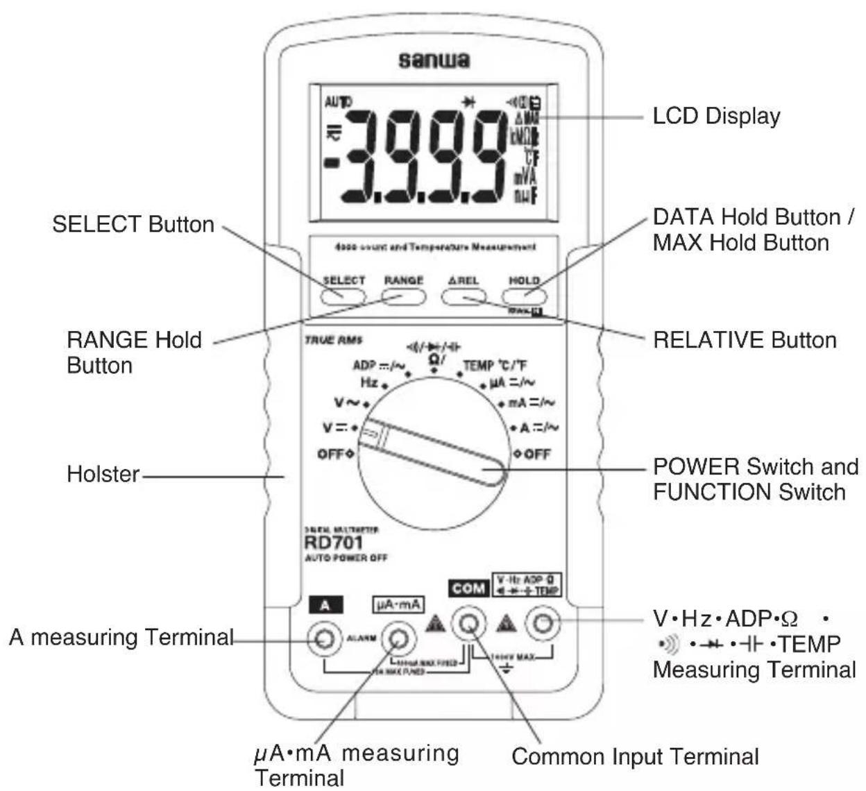
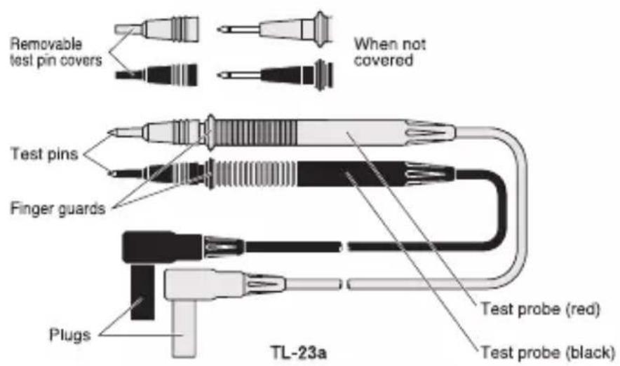
[3] NAME OF FUNCTIONS
[4] DESCRIPTION OF FUNCTIONS
4-1 Function Switch
Turn this switch to turn on and off the power and to select the functions of "V = / V \~ / Hz / ADP / Ω • • • • • • / TEMP / μA / mA / A".
4-2 Auto Power Off
The meter will enter a low power consumption sleep mode automatically to extend battery life after approximately 30 minutes of no function switch or push button operations. To wake up the meter from Auto Power Off, press any buttons momentarily or turn the function switch to the OFF position. Then turn back on again. To disable the Auto Power Off feature, press the SELECT button while turning the function switch on.
Note: Always turn the function switch to the OFF position when the meter is not in use.
4-3 Low Battery Indication
If the internal battery has been consumed and the internal battery drops below approx. 2.6 V, Battery mark is shown in the display.
4-4 Measurement Function Select
When the SELECT button is pressed (▶), the functions change as follows.
- In the case of ADP, A, mA & A, the modes change as:

- In the case of · , the modes change as:

- In the case of TEMP, the modes change as:

4-5 Range Hold : RANGE
Press the RANGE button momentarily to set the manual range mode then 'AUTO' disappears in the display. In manual range mode, press the button again to step through the ranges. To return to the auto mode, press the button for 1 sec. or more then AUTO is shown.
Note: Manual mode is not available in -1 and Hz measurement.
4-6 Data Hold : HOLD
When the HOLD button is pressed, the display is hold ('H' is shown on the display). The display will not changed while the function is active. Press the button again to cancel the function. ('H' on the display disappears.)
4-7 Max Hold: MAX H
The max feature displays the measured maximum value as fast as 30 ms in a single range, and with automatic up range capability. This function is able to use it with voltage measurement, current measurement and ADP measurement function. Press the MAX H button for 1 sec. or more to activate or to exit the max feature in the voltage or current functions.
4-8 Relative Mode : △ REL
Relative zero allows the user to offset the meter consecutive measurements with the displaying reading as the reference value. Press the REL button momentarily to activate and to exit relative zero mode.
4-9 Mis-insertion alarm for current function : ALARM
The instrument beeps to warn the user against possible damage to the instrument due to improper connections to the A , mA, or A input terminals when other function (like voltage measurement function) is selected.
4-10 Words
AC Sensing
Average RMS: RD700
When measurement is taken by "average", no error is caused as the input signal is shine wave with no distortion. However, if the input waveform is distorted sine cave or non-sinusoidal wave, conversion to root-mean-square values is very difficult, resulting in a large error.
AC coupling True RMS: RD701
When measurement is taken by true r.m.s., the measurement value of input signal becomes the scales of the signal power and therefore provide more effective values than those obtained by average value detection. This multimeter imploys this true RMS circuit, which enables measurement of sine wave and non-sinusoidal waves like square wave and triangular wave in r.m.s.
Crest Factor
The crest factor (CF) is expressed by a value obtained by dividing the peak value of the signal by its RMS value. Most common waveforms such as sine wave and triangular wave have a relatively low crest factor. The voltages and crest factors of typical waveforms are shown in the table.
| Input Waveform | Peak Vp | RMS Vrms | Average Vavg | CF Vp/Vrms | Form Factor Vrms/Vavg |
Sine WaveVp0 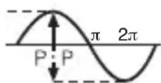 | Vrms 2=1.414 Vrms | 2 =0.707 Vp | 2 Vp =0.637 Vp | 2 =1.414 = | 22 =1.111 |
Square Wave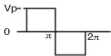 | Vp Vp | Vp 1 1 | |||
Triangular WaveVp0 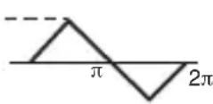 | Vrms· 3 =1.732 Vrms | 3 =0.577 Vp | 2 =0.5 Vp | 3 =1.732 = | 23 =1.155 |
Puls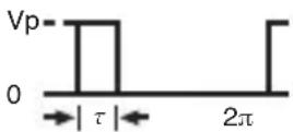 | Vp | 2 ·Vp | 2 ·Vp | 2 | 2 |
NMRR (Normal Mode Rejection Ratio)
NMRR is the DMM's ability to reject unwanted AC noise effect, which causes inaccurate DC measurements. NMRR is typically specified in terms of dB (decibel). This series has a NMRR specification of >60 dB at 50 and 60 Hz, which means a good ability to reject the effect of AC noise in DC measurements.
CMRR (Common Mode Rejection Ratio)
Common mode voltage is voltage present on both the COM and VOLTAGE input terminals of a DMM, with respect to ground. CMRR is the DMM's ability to reject common mode voltage effect, which causes digit rattle or offset in voltage measurements. This series has a CMRR specifications of >60 dB at DC to 60 Hz in ACV function; and >120 dB at DC, 50 and 60 Hz in DCV function.
[5] MEASUREMENT PROCEDURE
5-1 Start-Up Inspection

CAUTION
- Never use meter if the meter or test leads are damaged or broken.
- Make sure that the test leads are not cut or otherwise damaged.
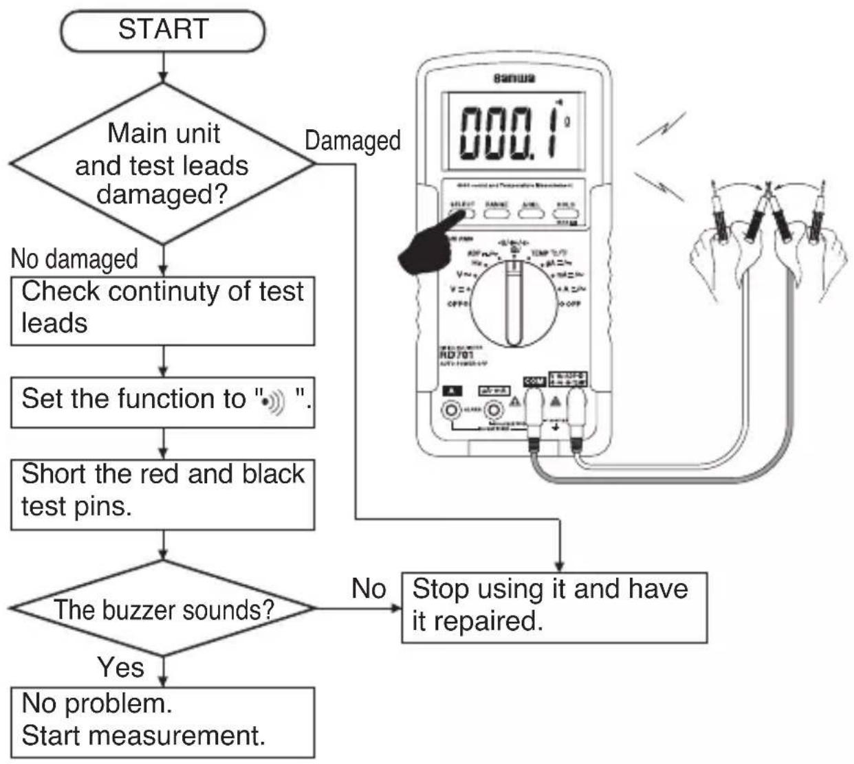
flowchart
graph TD
    A["START"] --> B{Main unit and test leads damaged?}
    B -->|No damaged| C["Check continuity of test leads"]
    C --> D["Set the function to ". . .""]
    D --> E["Short the red and black test pins."]
    E --> F{The buzzer sounds?}
    F -->|No| G["Stop using it and have it repaired."]
    F -->|Yes| H["No problem.<br>Start measurement."]
    G --> I["End"]
    style A fill:#f9f,stroke:#333
    style I fill:#ccf,stroke:#333
5-2 Voltage measurement / Frequency measurement
WARNING
-
Never apply an input signal exceeding the maximum rating input value.
-
Be sure to disconnect the test pins from the circuit when changing the function.
-
Always keep your fingers behind the finger guards on the probe when making measurements.
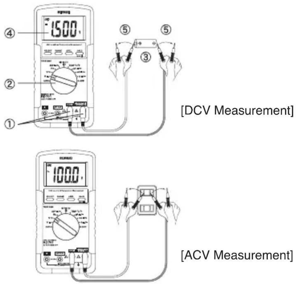
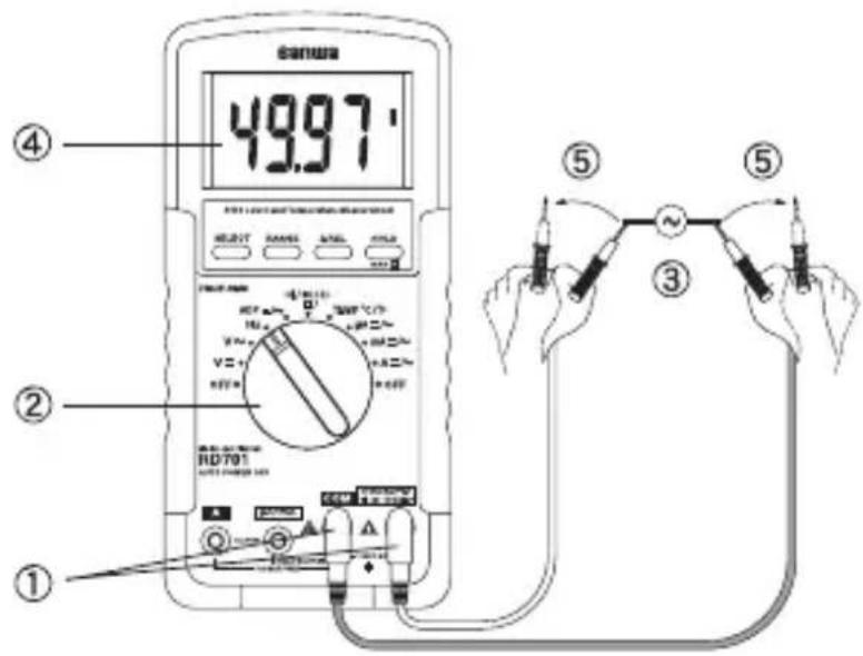
5-2-1 Voltage measurements
DC/ACV: Maximum rating input value 1000 VDC/AC
1) Applications
DCV: Voltage of the battery and DC circuit are measured.
ACV: Sine wave AC voltage such as lighting voltage is measured.
2) Measuring ranges
DCV & ACV: 5 ranges from 400.0 mV to 1000 V
3) Measurement procedure
① Connect the plug of black test lead to COM terminal and plug of red test lead to V terminal.
② Set the function switch to 'V ==' or 'V \~'.
③ Apply the red and black test pins to the circuit to measure.
For measurement of DCV, apply the black test pin to the negative potential side of the circuit to measure and the red test pin to the positive potential side.
For measurement of ACV, apply the red and black test pins to the circuit to measure.
④ The reading of Voltage is shown in the display.
⑤ After measurement, release the red and black test pins from the object measured.
Note:
1) AC 400.0 mV range selection is the manual operation switching by RANGE button.
2) It may fluctuate the value when the input terminal is opened, because the input impedance of DC/AC 400.0 mV range is 1000 MΩ. But this is not malfunction and there is not hindrance in measurement.
3) The accuracy is not specified from 0 to AC 10 mV (RD701: 0\~AC 40 mV) when the function was set up to the ACmV range.
4) The reading does not become 0 when the input terminal was shorted. But this does not bring about the influence to measurement.
5-2-2 Frequency measurement
1) Application
Frequency of an AC circuit is measured.
2) Measuring ranges
10.00 Hz to 1.000 MHz (Auto range)
3) Measurement procedure
① Connect the plug of black test lead to COM measuring input terminal and plug of red test lead to Hz measuring terminal.
② Set the function switch to 'Hz'.
③ Apply the red and black test pins to an object to measure.
④ The reading of Voltage is shown in the display.
⑤ After measurement, release the red and black test pins from the object measured.
Note: Operating input voltage: < 20 VAC rms.
Input Signal: Sine wave, or Square wave with duty cycle 40%\~70%
Sensitivity : 10 Hz\~20 kHz : > 0.9 Vrms
20 kHz\~500 kHz : > 2.6 Vp or 1.9 Vrms
500 kHz\~1 MHz : > 4.2 Vp or 3 Vrms
Update Rate: 2 per second nominal
5-3 Adapter measurement
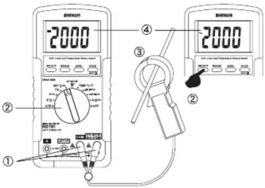
1) Applications
This function is to measure with optional clamp probe (CL-22 AD and CL33DC), and like.
It can measure with this function, if it is the probe like the following.
◆ Current clamp probe with 1 mV (Up to 400 mV) output per 1 A.
2) How to use
①Connect the plug of black test lead or '-' to COM input terminal and plug of red test lead or '+' to ADP input terminal.
② Set the function switch to 'ADP' and select either 'DC ÷ or 'AC \~' by pressing the SELECT button.
③ Open the clamp part, have electric wire (one line) clamped, and close the clamp part perfectly.
④ The reading is shown in the display. (1mV is indicated as 10 counts.)
- In case of a current clamp probe with 1mV output per 1 A, a display of '1000' counts on the display represents '100 A'.
⑤ After measurement, open the clamp part and release clamp probe from the electric wire.
[Adapter (ADP) indication example]
| Clamp Probe | Range | Probe Output DMM Display | Reading value | |
| CL-22AD | DC 20 A* | DC 15 mV | DC 0150 | 1.5 A |
| DC 200 A | DC 150 mV | DC 1500 | 150 A | |
| AC 20 A* | AC 15 mV | AC 0150 | 1.5 A | |
| AC 200 A | AC 150 mV | AC 1500 | 150 A | |
| CL33DC | DC 30 A* | DC 25 mV | DC 0250 | 2.5 A |
| DC 300 A | DC 250 mV | DC 2500 | 250 A | |
*: This range is 1 mV output per 0.1 A.
5-4 Resistance measurement and Capacitance measurement / Testing Diode / Checking Continuity

WARNING
Never apply voltage to the input terminals.
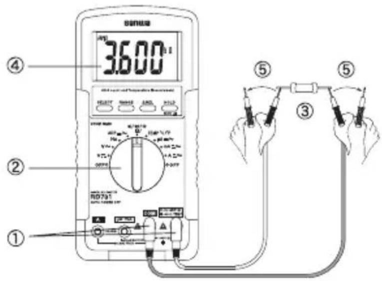
5-4-1 Resistance Measurement
1) Applications
Resistance of resistors and circuits are measured.
2) Measuring ranges
6 ranges from 400.0 Ω to 40.00 M Ω .
3) Measurement procedure
①Connect the plug of black test lead to COM input terminal and plug of red test lead to input terminal.
② Set the function switch to 'Ω / •/ → / +' and select 'Ω' by pressing the SELECT button.
③Apply the red and black test pins to an object to measure.
④The reading is shown in the display.
⑤ After measurement, release the red and black test pins from the object measured.
Note: If measurement is likely to be influenced by noise, shield the object to measure with negative potential (COM).
If a finger touches a test pin during measurement, measurement will be influenced by the resistance in the human body to result in measurement error.
Open Circuit Voltage: <0.4 VDC typical
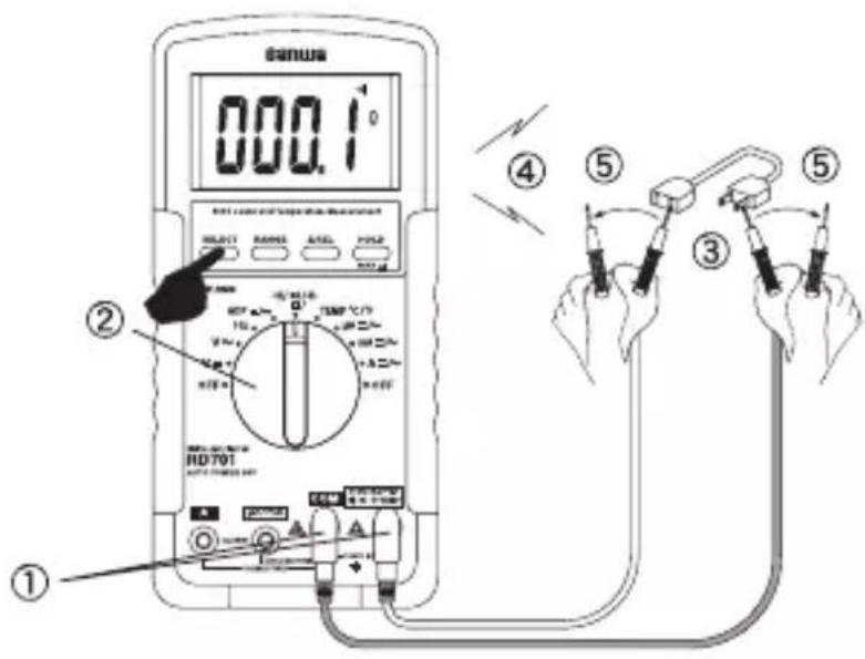
5-4-2 Checking Continuity
1) Application
Checking the continuity of wiring and selecting wires.
2) How to use
① Connect the plug of black test lead to COM measuring input terminal and plug of red test lead to measuring terminal.
② Set the function switch at 'Ω / •/ → /+ -' and select ••' with the SELECT button.
③ Apply the red and black test pins to a circuit or conductor to measure.
④ The continuity can be judged by whether the buzzer sounds or not.
⑤ After measurement, release the red and black test pins from the object measured.
Note: Threshold: between 20 Ω and 120 Ω.
Open Circuit Voltage: <0.4 VDC typical
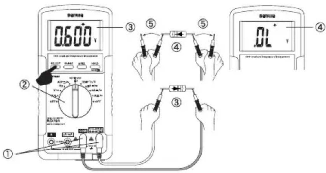
5-4-3 Testing Diode
1) Application
The quality of diodes is tested.
2) How to use
①Connect the plug of black test lead to COM measuring input terminal and plug of red test lead to →measuring terminal.
② Set the function switch at 'Ω / •/→/+ -' and select '→' with the SELECT switch.
③Apply the black test pins to the cathode of the diode and the red test pin to the anode.
Check reading for judgment of good or defective.
√ A zero reading indicates a shorted diode (defective).
√ An 'OL' indicates an open diode (defective).
④Apply the red test pins to the cathode of the diode and the black test pin to the anode
√ The display shows 'OL', if diode is good. Any other readings indicated the diode is resistive or shorted (defective).
⑤ After measurement, release the red and black test pins from the object measured.
Note: The input terminals release voltage is about <1.6 V.
5-4-4 Capacitance Measurement

CAUTION
- Discharge the capacitance before measurement.
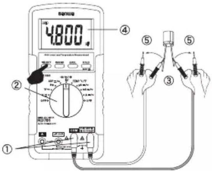
- Due to the measurement method that this device pours the current into a capacitor the measurement such as the big electrolysis capacitor of a leakage current is not suited in order that the error becomes big.
1) Application
Measures capacitance of condensor.
2) Measuring ranges
5 ranges from 500.0 nF to 3000 μF (Auto range)
3) Measurement procedure
① Connect the plug of black test lead to COM measuring input terminal and plug of red test lead to -1- measuring terminal.
② Set the function switch to 'Ω / •/ → /→' and select '-→' by pressing the SELECT button.
③ Apply the red and black test pins to an object to measure.
④ Read the value in the display.
⑤ After measurement, release the red and black test pins from the object measured.
5-5 Temperature Measurement
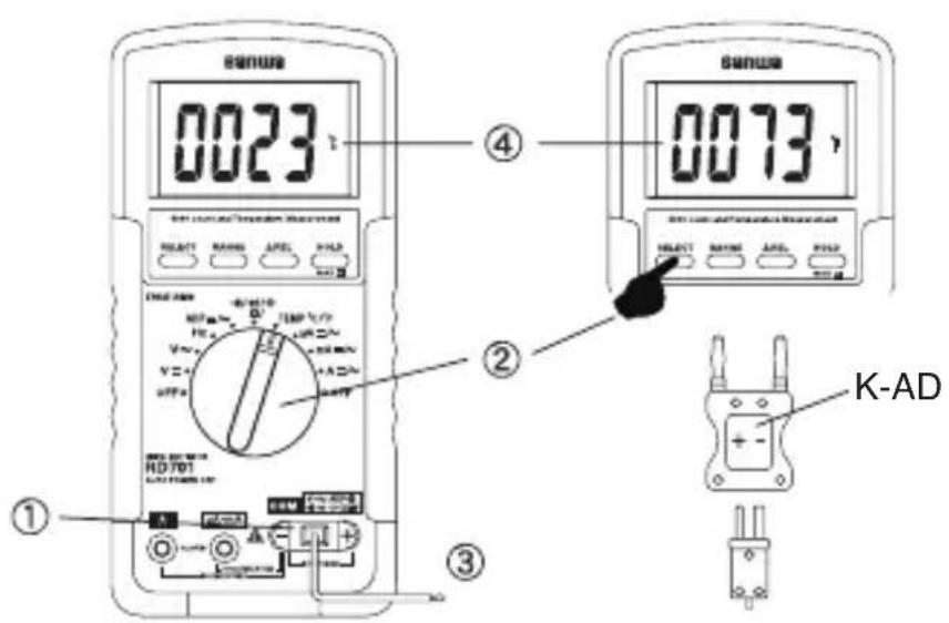
1) Application
The temperature of outside and water, object is measured.
2) Measuring ranges
Range from -20 °C to 300 °C
Fahrenheit: Range from -4 to 572 °F
3) Measurement procedure
① Input the -plug to COM input terminal and the +plug to Temp terminal.
② Set the function switch to 'Temp' and select either '°C' or '°F' by pressing the SELECT switch.
③Apply the sensor of K-250PC (-50°C\~250°C / -58°F\~482°F) to an object to measure.
④Read the value in the display.
⑤ After measurement, release the sensor from the object measured.
NOTE: In the case that other optional temperature sensors are used, it connects to DMM by using optional K-type adapter (K-AD).
5-6 Current Measurement

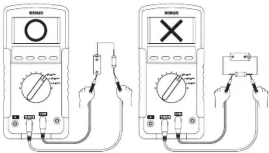
WARNING
- Never apply voltage to the input terminals.
- Be sure to make a series connection via load.
-
Do not apply an input exceeding the maximum rated current to the input terminals.
-
Before starting measurement, turn OFF the power switch of the circuit to separate the measuring part and connect the test leads firmly.
-
The meter beeps to warn the user against possible damage to the meter due to improper connections to the A / mA , or A input terminals when other function (like voltage function) is selected.
DCμA, mA: Maximum rating input value 400 mADC
ACμA, mA: Maximum rating input value 400 mAAC
DCA: Maximum rating input value 10 ADC
ACA: Maximum rating input value 10 AAC
1) Applications
DCA: Current in batteries and DC circuits is measured.
ACA: Current in AC circuits is measured.
2) Measuring ranges
DC/ACμA, mA: 4 ranges for 400.0 μA/4000 μA and 40.00
mA/400.0 mA
DC/ACA: 2 ranges for 4.000 A, 10.00 A
3) Measurement procedure
①Connect the plug of black test lead to COM measuring input terminal and plug of red test lead to A / mA or A measuring terminal.
② Set the function switch to 'μA' or 'mA' or 'A' and select either 'DC' or 'AC' by pressing the SELECT button.
③In the circuit to measure and apply the red and black test pins in series with load.
For measurement of DCA, apply the black test pin to the negative potential side of the circuit to measure and the red test pin to the positive potential side in series with load.
For measurement of ACA, apply the red and black test pins to the circuit to measure in series with load.
④ Apply the red and black test pins to the circuit to measure.
⑤Read the value in the display.
⑥ After measurement, remove the red and black test pins from the circuit measured.
Note:10 A continuous
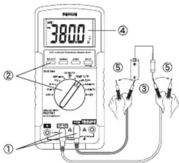
[μA·mA Measurement]
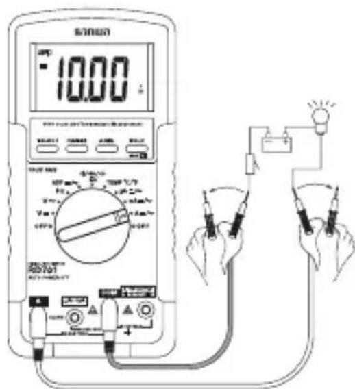
[A Measurement]
[6] MAINTENANCE
![Sanwa RD701 - [6] MAINTENANCE - 1](/content/2026/05/982930/images/f7e138be5c158c1eef50021512f3e5b7a85dd677920b2a59178a13fde8446af8.jpg)
WARNING
-
This section is very important for safety. Read and understand the following instruction fully and maintain your instrument properly.
-
The instrument must be calibrated and inspected at least once a year to maintain the safety and accuracy.
6-1 Maintenance and Inspection
1) Appearance
- Does falling not damage the appearance?
2) Test leads
● Is the cord of the test leads not damaged?
● Is the core wire not exposed at any place of the test leads?
NOTE: If the built-in fuse is blown, only the current measurement becomes impossible.
Make sure that the test leads are not cut, referring to the section 5-1.
6-2 Calibration
The manufacturer may conduct the calibration and inspection. For more information, please contact the manufacturer.
6-3 Battery and Fuse Replacement

WARNING
- If the rear case or the battery lid is removed with input applied to the input terminals, you may get electrical shock. Before starting the work, always make sure that no input is applied.
- Before starting the work, be sure to turn OFF the main unit power and release the test leads from the circuit.
- Be sure to use a fuse of the specified rating or type. Never use a substitute of the fuse or never make a short circuit of the fuse.
Factory-preinstalled built-in battery
A battery for monitoring is preinstalled before shipping, therefore it may run down sooner than the battery life specified in the instruction manual.
The "battery for monitoring" is a battery to inspect the functions and specifications of the product.
① Remove the battery lid screw with a screwdriver.
② Removed the battery lid.
③ Take out the battery or fuse and replace it with a new one.
④ Attach the battery lid and fix it with the screw.
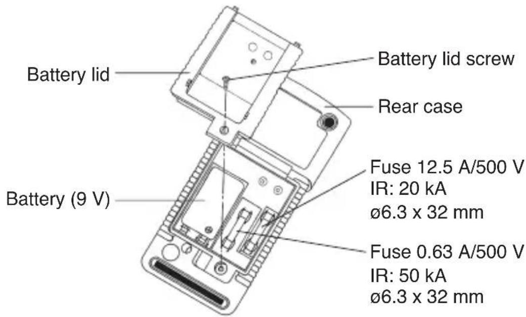

CAUTION
Set a battery with its polarities facing in the correct directions.
6-4 Storage

CAUTION
- The panel and the case are not resistant to volatile solvent and must not be cleaned with thinner or alcohol. For cleaning, use dry, soft cloth and wipe it lightly.
- The panel and the case are not resistant to heat. Do not place the instrument near heat-generating devices (such as a soldering iron).
- Do not store the instrument, in a place where it may be subjected to vibration or from where it may fall.
- For storing the instrument, avoid hot, cold or humid places or places under direct sunlight or where condensation is anticipated.
Following the above instructions, store the instrument in good environment. (See 8-1)
[7] AFTER-SALE SERVICE
7-1 Warranty and Provision
Sanwa offers comprehensive warranty services to its end-users and to its product resellers. Under Sanwa's general warranty policy, each instrument is warranted to be free from defects in workmanship or material under normal use for the period of one
(1) year from the date of purchase.
This warranty policy is valid within the country of purchase only, and applied only to the product purchased from Sanwa authorized agent or distributor.
Sanwa reserves the right to inspect all warranty claims to determine the extent to which the warranty policy shall apply.
This warranty shall not apply to fuses, disposables batteries, or any product or parts, which have been subject to one of the following causes:
- A failure due to improper handling or use that deviates from the instruction manual.
- A failure due to inadequate repair or modification by people other than Sanwa service personnel.
- A failure due to causes not attributable to this product such as fire, flood and other natural disaster.
- Non-operation due to a discharged battery.
- A failure or damage due to transportation, relocation or dropping after the purchase.
7-2 Repair
Customers are asked to provide the following information when requesting services:
- Description of problem
- Description of product configuration
- Model Number
- Product Serial Number
- Proof of Date-of-Purchase
-
Where you purchased the product
-
Customer name, address, and contact information
1) Prior to requesting repair, please check the following:
Capacity of the built-in battery, polarity of installation and discontinuity of the test leads.
2) Repair during the warranty period:
The failed meter will be repaired in accordance with the conditions stipulated in 7-1 Warranty and Provision.
3) Repair after the warranty period has expired:
In some cases, repair and transportation cost may become higher than the price of the product. Please contact Sanwa authorized agent / service provider in advance.
The minimum retention period of service functional parts is 6 years after the discontinuation of manufacture. This retention period is the repair warranty period. Please note, however, if such functional parts become unavailable for reasons of discontinuation of manufacture, etc., the retention period may become shorter accordingly.
4) Precautions when sending the product to be repaired
To ensure the safety of the product during transportation, place the product in a box that is larger than the product 5 times or more in volume and fill cushion materials fully and then clearly mark "Repair Product Enclosed" on the box surface. The cost of sending and returning the product shall be borne by the customer.
7-3 SANWA web site
http://www.sanwa-meter.co.jp
E-mail: exp_sales@sanwa-meter.co.jp
[8] SPECIFICATIONS
8-1 General Specification
Display:
4000 counts LCD (Hz: 9999 counts, -1 : 5000 counts)
Update Sampling Rate:
3 per second nominal (Hz: 2 per second nominal)
Low Battery Indication:
Below approx. 2.6 V, "☐" mark indication
Range Selection:
Auto and Manual ranges (partially Manual range or Auto range only)
Polarity Indication:
Automatic selection ("-" is indicated when negative voltage is inputted.)
Over ranging Indication:
"OL" mark indication
Over ranging Indication:
"OL" mark indication
Operating Temperature:
0℃\~40℃, 0\~80% R.H.; 35℃\~50℃, 0\~70% R.H.
Relative Humidity:
Maximum relative humidity 80 % for temperature up to 31°C decreasing linearly to 50 % relative humidity at 40°C
Storage Temperature:
-20℃\~60℃, 80% R.H. (With battery removed)
Altitude:
Operating below 2000 m
Temperature Coefficient:
Nominal 0.15x (specified accuracy)/°C @ (0°C \~18°C or 28°C \~50°C), or otherwise specified
Power Supply:
9 V battery; NEDA1604, JIS006P or IEC6F22
Sensing:
Average Sensing for RD700. True RMS for RD701
Transient protection:
6.5 kV (1.2/50 s surge)
Pollution degree:
2
Power Consumption:
3.2 mA Typical
Auto Power Off Timing:
Idle for 30 minutes
Auto Power Off Function Consumption:
300 A typical for RD700; 360 A typical for RD701
Dimension:
179(H) × 87(W) × 55(D) mm with holster
Mass:
320 g / 460 g with holster
Accessories:
Test leads:TL-23a, K-type thermocouple: K-250PC
Holster: H-50
Instruction manual: RD700/RD701
Optional Accessories:
K-type adapter: K-AD
Clamp Probe: CL3000, CL-22AD, and CL33DC

8-2 Measurement Range and Accuracy
Accuracy assurance range: 23±5 °C & less than 75 % R.H.
| Function & Range Accuracy | Input Impedance | Remarks | ||
| DCV | 400.0 mV | ±(0.3 %rdg + 4 dgt) | 1000 MΩ | NMRR: >50 dB@50/60 HzCMRR: >120 dB@DC, 50/60 Hz, Rs=1 kΩ |
| 4.000 V | ±(0.5 %rdg + 3 dgt) | 10 MΩ, 30 pF nominal | ||
| 40.00 V | ||||
| 400.0 V | ||||
| 1000 V | ±(1.0 %rdg + 4 dgt) | |||
| ACV1) | 400.0 mV | ±(4.0 %rdg + 5 dgt) | 1000 MΩ | 50~500 HzCMRR:>60 dB@DC to 60 Hz, Rs=1 kΩ |
| 4.000 V | ±(1.5 %rdg + 5 dgt) | 10 MΩ, 30 pF nominal | ||
| 40.00 V | ||||
| 400.0 V | ||||
| 1000 V | ±(4.0 %rdg + 5 dgt) | |||
| Ω | 400.0 Ω | ±(0.8 %rdg + 6 dgt) | Open Circuit Voltage: <0.4 VDC typical | |
| 4.000 kΩ | ±(0.6 %rdg + 4 dgt) | |||
| 40.00 kΩ | ||||
| 400.0 kΩ | ||||
| 4.000 MΩ | ±(1.0 %rdg + 4 dgt) | |||
| 40.00 MΩ | ±(2.0 %rdg + 4 dgt) | |||
| -1- | 500.0 nF | ±(2.5 %rdg + 6 dgt)2) | Additional 50.00 nF range accuracy is not specified.Accuracies with film capacitor or better. | |
| 5.000 μF | ||||
| 50.00 μF | ||||
| 500.0 μF | ||||
| 3000 μF | ||||
| Hz | 50.00 Hz | ±(0.5 %rdg + 4 dgt) | Operating input voltage: <20 Vrms.Input Signal: Sine wave, or Square wave with duty cycle 40%~70%Sensitivity: 10 Hz~20 kHz: >0.9 Vrms20 kHz~500 kHz: >2.6 Vp or 1.9 Vrms500 kHz~1 MHz: >4.2 Vp or 3 VrmsUpdate Rate: 2 per second nominal | |
| 500.0 Hz | ||||
| 5.000 kHz | ||||
| 50.00 kHz | ||||
| 500.0 kHz | ||||
| 1.000 MHz | ||||
| TEMP | -20~300°C | ±(2 %rdg + 3 °C) | Type-K thermocouple range & accuracy not included | |
| -4~572°F | ±(2 %rdg + 6 °F | |||
1) Model RD701 True RMS accuracy of ACV, ACA & AC-ADP is specified from 5 % (10 % for AC 400.0 mV range) to 100 % of range, or otherwise specified. Maximum Crest Factor < 1.75: 1 at full scale & < 3.5: 1 at half scale, and with frequency components within the specified frequency bandwidth for non-sinusoidal waveforms.
2) Specified with battery voltage above 2.8 V. Accuracy decreases gradually to 12 % at low battery warning voltage of approximately 2.6 V.
| skrameRegnaR & noitchnuF | ||
| → | 2.000 V | Test Current (Typical): 0.25 mAOpen Circuit Voltage: < 1.6 VDC |
| • | 400.0 Ω | Audible threshold: Between 20 Ω and 120 Ω.Open circuit voltage: <0.4 VDC typical. |
| Function & Range Accuracy | Burden Voltage | Remarks | ||
| DCA | 400.0 μA | ±(2.0 %rdg + 5 dgt) | 0.15 mV/μA | *: 10 A continuous |
| 4000 μA | ±(1.2 %rdg + 3 dgt) | |||
| 40.00 mA | ±(2.0 %rdg + 5 dgt) | 3.3 mV/mA | ||
| 400.0 mA | ±(1.2 %rdg + 3 dgt) | |||
| 4.000 A | ±(2.0 %rdg + 5 dgt) | 0.03 V/A | ||
| 10.00 A* | ±(1.2 %rdg + 3 dgt) | |||
| ACA1) | 400.0 μA | ±(2.0 %rdg + 6 dgt) | 0.15 mV/μA | 50 Hz~500 Hz*: 10 A continuous |
| 4000 μA | ±(1.5 %rdg + 4 dgt) | |||
| 40.00 mA | ±(2.0 %rdg + 6 dgt) | 3.3 mV/mA | ||
| 400.0 mA | ±(1.7 %rdg + 4 dgt) | |||
| 4.000 A | ±(2.0 %rdg + 6 dgt) | 0.03 V/A | ||
| 10.00 A* | ±(1.8 %rdg + 4 dgt) | |||
| Function Accuracy | 3) | Input Impedance | Remarks | |
| ADP | DC | ±(0.3 %rdg + 4 dgt) | 1000 MΩ,30 pFnominal | —— |
| AC1) | ±(1.5 %rdg + 5 dgt) | RD700: 50 Hz~500 HzRD701: 50 Hz~3 kHz | ||
3) The accuracy of the sensor is not included.
Accuracy calculation
For example... Measurement 400 mVDC Range
Display value : 100.0 [mV]
Accuracy : 400.0 [mV] Range...±(0.3 %rdg + 4 dgt)
Error : ±(100.0 [mV] 0.3 %rdg + 4 dgt) = ±0.7 [mV]
Calculation : 100.0 [mV] ± (100.0 [mV] 0.3 %rdg + 4 dgt)
True value : In a range of 099.3 [mV] \~ 100.7 [mV]
*4 [dgt] in the 400.0 [mV] range correspond to 0.4 [mV].
※Do not use the tester near places where strong electromagnetic waves and trance are generated or strong electrical voltages are generated.
Specifications and external appearance of the product described above may be revised for modification without prior notice.
MEMO
sanwa®
SANWA ELECTRIC INSTRUMENT CO.,LTD.
Dempa Bldg, Sotokanda2-Chome Chiyoda-Ku, Tokyo, Japan
- [1] SAFETY PRECAUTIONS
- [2] APPLICATION AND FEATURES 3
- [3] NAME OF FUNCTION 4
- [4] DESCRIPTION OF FUNCTIONS
- [5] MEASUREMENT PROCEDURE
- [6] MAINTENANCE
- [7] AFTER-SALE SERVICE
- [8] SPECIFICATIONS
- \*Before use, read the following safety precautions.
- 1-1 Explanation of Warning Symbols
- ⚠️: Very important instruction for safe use.
- ⚠️: Dangerous voltage (Take care not to get an electric shock in voltage measurement.)
- 1-2 Warning Instruction for Safe Use
- WARNING
- [2] APPLICATION AND FEATURES
- 2-1 Applications
- 2-2 Features
- 4-1 Function Switch
- 4-2 Auto Power Off
- 4-3 Low Battery Indication
- 4-4 Measurement Function Select
- 4-5 Range Hold : RANGE
- 4-6 Data Hold : HOLD
- 4-7 Max Hold: MAX H
- 4-8 Relative Mode : △ REL
- 4-9 Mis-insertion alarm for current function : ALARM
- 4-10 Words
- AC Sensing
- Average RMS: RD700
- AC coupling True RMS: RD701
- Crest Factor
- NMRR (Normal Mode Rejection Ratio)
- CMRR (Common Mode Rejection Ratio)
- 5-1 Start-Up Inspection
- CAUTION
- 5-2 Voltage measurement / Frequency measurement
- 5-2-1 Voltage measurements
- DC/ACV: Maximum rating input value 1000 VDC/AC
- 1) Applications
- 2) Measuring ranges
- 3) Measurement procedure
- Note:
- 5-2-2 Frequency measurement
- 1) Application
- 5-3 Adapter measurement
- 2) How to use
- 5-4 Resistance measurement and Capacitance measurement / Testing Diode / Checking Continuity
- 5-4-1 Resistance Measurement
- 5-4-2 Checking Continuity
- 5-4-3 Testing Diode
- Check reading for judgment of good or defective.
- 5-4-4 Capacitance Measurement
- 5-5 Temperature Measurement
- 5-6 Current Measurement
- 6-1 Maintenance and Inspection
- 1) Appearance
- 2) Test leads
- 6-2 Calibration
- 6-3 Battery and Fuse Replacement
- Factory-preinstalled built-in battery
- 6-4 Storage
- 7-1 Warranty and Provision
- 7-2 Repair
- 7-3 SANWA web site
- 8-1 General Specification
- Display:
- Update Sampling Rate:
- Low Battery Indication:
- Range Selection:
- Polarity Indication:
- Over ranging Indication:
- Operating Temperature:
- Relative Humidity:
- Storage Temperature:
- Altitude:
- Temperature Coefficient:
- Power Supply:
- Sensing:
- Transient protection:
- Pollution degree:
- Power Consumption:
- Auto Power Off Timing:
- Auto Power Off Function Consumption:
- Dimension:
- Mass:
- Accessories:
- Optional Accessories:
- 8-2 Measurement Range and Accuracy
- Accuracy calculation
- sanwa®
- SANWA ELECTRIC INSTRUMENT CO.,LTD.
Brand : Sanwa
Model : RD701
Category : Multimeter