
NCITE-813AC - Système de présentation vidéo AMX - Free user manual and instructions
Find the device manual for free NCITE-813AC AMX in PDF.


| Product Type | AV Control System |
| Brand | AMX |
| Model | NCITE-813AC |
| Dimensions (H x W x D) | 1.75 x 19 x 8.5 inches (1U rack mount) |
| Weight | 5.5 lbs (2.5 kg) |
| Power Supply | 100–240 VAC, 50/60 Hz, internal PSU |
| Power Consumption | 30W max |
| Ethernet Ports | 2 x RJ-45 (10/100 Mbps) |
| Serial Ports | 2 x RS-232/422/485 (DB9) |
| IR Ports | 4 x IR emitter outputs, 1 x IR receiver input |
| Relay Ports | 4 x relay outputs (programmable) |
| I/O Ports | 4 x digital I/O (voltage sense or contact closure) |
| USB Ports | 1 x USB-B (for programming) |
| Operating System | NetLinx NX-based firmware |
| Control Protocols | AMX NetLinx, ICSP, Telnet, HTTP, SNMP |
| LED Indicators | Power, Link/Act, Status, Programming |
| Cooling | Fanless, heatsink design |
| Operating Temperature | 32°F to 104°F (0°C to 40°C) |
| Storage Temperature | -4°F to 158°F (-20°C to 70°C) |
| Certifications | FCC Part 15, CE, RoHS |
| Cleaning Instructions | Wipe with dry cloth; avoid liquids and abrasive cleaners |
| Maintenance | No user-serviceable parts; refer to qualified service personnel |
Frequently Asked Questions - NCITE-813AC AMX
User questions about NCITE-813AC AMX
0 question about this device. Answer the ones you know or ask your own.
Ask a new question about this device
Download the instructions for your Système de présentation vidéo in PDF format for free! Find your manual NCITE-813AC - AMX and take your electronic device back in hand. On this page are published all the documents necessary for the use of your device. NCITE-813AC by AMX.
USER MANUAL NCITE-813AC AMX
IMPORTANT SAFETY INSTRUCTIONS
-
READ these instructions.
-
KEEP these instructions.
-
HEED all warnings.
-
FOLLOW all instructions.
-
DO NOT use this apparatus near water.
-
CLEAN ONLY with dry cloth.
-
DO NOT block any ventilation openings. Install in accordance with the manufacturer's instructions.
-
DO NOT install near any heat sources such as radiators, heat registers, stoves, or other apparatus (including amplifiers) that produce heat.
-
DO NOT defeat the safety purpose of the polarized or grounding type plug. A polarized plug has two blades with one wider than the other. A grounding type plug has two blades and a third grounding prong. The wider blade or the third prong are provided for your safety. If the provided plug does not fit into your outlet, consult an electrician for replacement of the obsolete outlet.
-
PROTECT the power cord from being walked on or pinched, particularly at plugs, convenience receptacles, and the point where they exit from the apparatus.
-
ONLY USE attachments/accessories specified by the manufacturer.

-
USE ONLY with a cart, stand, tripod, bracket, or table specified by the manufacturer, or sold with the apparatus. When a cart is used, use caution when moving the cart/apparatus combination to avoid injury from tip-over.
-
UNPLUG this apparatus during lightning storms or when unused for long periods of time.
-
REFER all servicing to qualified service personnel. Servicing is required when the apparatus has been damaged in any way, such as power-supply cord or plug is damaged, liquid has been spilled or objects have fallen into the apparatus, the apparatus has been exposed to rain or moisture, does not operate normally, or has been dropped.
-
DO NOT expose this apparatus to dripping or splashing and ensure that no objects filled with liquids, such as vases, are placed on the apparatus.
-
To completely disconnect this apparatus from the AC Mains, disconnect the power supply cord plug from the AC receptacle.
-
Where the mains plug or an appliance coupler is used as the disconnect device, the disconnect device shall remain readily operable.
-
DO NOT overload wall outlets or extension cords beyond their rated capacity as this can cause electric shock or fire.

The exclamation point, within an equilateral triangle, is intended to alert the user to the presence of important operating and maintenance (servicing) instructions in the literature accompanying the product.

The lightning flash with arrowhead symbol within an equilateral triangle is intended to alert the user to the presence of uninsulated "dangerous voltage" within the product's enclosure that may be of sufficient magnitude to constitute a risk of electrical shock to persons.

ESD Warning: The icon to the left indicates text regarding potential danger associated with the discharge of static electricity from an outside source (such as human hands) into an integrated circuit, often resulting in damage to the circuit.
WARNING: To reduce the risk of fire or electrical shock, do not expose this apparatus to rain or moisture.
WARNING: No naked flame sources - such as candles - should be placed on the product.
WARNING: Equipment shall be connected to a MAINS socket outlet with a protective earthing connection.
COPYRIGHT NOTICE
AMX© 2015, all rights reserved. No part of this publication may be reproduced, stored in a retrieval system, or transmitted, in any form or by any means, electronic, mechanical, photocopying, recording, or otherwise, without the prior written permission of AMX. Copyright protection claimed extends to AMX hardware and software and includes all forms and matters copyrightable material and information now allowed by statutory or judicial law or herein after granted, including without limitation, material generated from the software programs which are displayed on the screen such as icons, screen display looks, etc. Reproduction or disassembly of embodied computer programs or algorithms is expressly prohibited.
LIABILITY NOTICE
No patent liability is assumed with respect to the use of information contained herein. While every precaution has been taken in the preparation of this publication, AMX assumes no responsibility for error or omissions. No liability is assumed for damages resulting from the use of the information contained herein. Further, this publication and features described herein are subject to change without notice.
AMX WARRANTY AND RETURN POLICY
The AMX Warranty and Return Policy and related documents can be viewed/downloaded at www.amx.com.
ESD WARNING

To avoid ESD (Electrostatic Discharge) damage to sensitive components, make sure you are properly grounded before touching any internal materials.
When working with any equipment manufactured with electronic devices, proper ESD grounding procedures must be followed to make sure people, products, and tools are as free of static charges as possible. Grounding straps, conductive smocks, and conductive work mats are specifically designed for this purpose. These items should not be manufactured locally, since they are generally composed of highly resistive conductive materials to safely drain static discharges, without increasing an electrocution risk in the event of an accident.
Anyone performing field maintenance on AMX equipment should use an appropriate ESD field service kit complete with at least a dissipative work mat with a ground cord and a UL listed adjustable wrist strap with another ground cord.


WARNING: Do Not Open! Risk of Electrical Shock. Voltages in this equipment are hazardous to life. No user-serviceable parts inside. Refer all servicing to qualified service personnel.
Place the equipment near a main power supply outlet and make sure that you can easily access the power breaker switch.
WARNING: This product is intended to be operated ONLY from the voltages listed on the back panel or the recommended, or included, power supply of the product. Operation from other voltages other than those indicated may cause irreversible damage to the product and void the products warranty. The use of AC Plug Adapters is cautioned because it can allow the product to be plugged into voltages in which the product was not designed to operate. If the product is equipped with a detachable power cord, use only the type provided, or specified, by the manufacturer or your local distributor.
BATTERY INSTRUCTIONS:
THIS PRODUCT CONTAINS A LITHIUM PACK OR COIN/BUTTON CELL BATTERY. IF MISUSED OR ABUSED THIS CAN RESULT IN:
- Smoke or gas hazard
- Heat hazard
- Fire hazard
- Explosion hazard
WARNING: Do not place batteries in mouth or ingest. Chemical burn hazard. Keep new and used batteries out of reach of children and pets. If swallowed, it can cause severe internal burns in just 2 hours and can lead to death.
If you think batteries might have been swallowed or placed inside any part of the body, seek immediate medical attention.
WARNING: If battery compartment does not close securely, stop using the product and keep it away from children and pets.
WARNING: Do not handle leaking or damaged Lithium batteries.
WARNING: Risk of leakage. Only use the specified type of batteries. Never mix new and used batteries.
Observe correct polarity. Remove batteries from products that are not in use for extended periods of time. Store batteries in a dry place.
WARNING: Batteries (battery pack or batteries installed) shall not be exposed to excessive heat such as sunshine, fire or the like.
WARNING: Danger of explosion if battery is incorrectly replaced. Replace only with the same or equivalent type.
Dispose of used batteries according to the instructions.
WARNING: Do not recharge non-rechargeable batteries.
WARNING: Avoid exposure to extreme heat or cold.
Please dispose of any used batteries properly, following any local regulations. Do not incinerate.
WARNING: Disposal of a battery into fire or a hot oven, or mechanically crushing or cutting of a battery, can result in an explosion.
RACK MOUNTING:
A) Elevated Operating Ambient - If installed in a closed or multi-unit rack assembly, the operating ambient temperature of the rack environment may be greater than room ambient. Therefore, consideration should be given to installing the equipment in an environment compatible with the maximum ambient temperature (Tma) specified by the manufacturer.
B) Reduced Air Flow - Installation of the equipment in a rack should be such that the amount of air flow required for safe operation of the equipment is not compromised.
C) Mechanical Loading - Mounting of the equipment in the rack should be such that a hazardous condition is not achieved due to uneven mechanical loading.
D) Circuit Overloading - Consideration should be given to the connection of the equipment to the supply circuit and the effect that overloading of the circuits might have on overcurrent protection and supply wiring. Appropriate consideration of equipment nameplate ratings should be used when addressing this concern.
E) Reliable Earthing - Reliable earthing of rack-mounted equipment should be maintained. Particular attention should be given to supply connections other than direct connections to the branch circuit (e.g. use of power strips).”
FCC AND CANADA EMC COMPLIANCE INFORMATION:
This device complies with part 15 of the FCC Rules. Operation is subject to the following two conditions:
(1) This device may not cause harmful interference, and (2) this device must accept any interference received, including interference that may cause undesired operation.
NOTE: This equipment has been tested and found to comply with the limits for a Class A digital device, pursuant to part 15 of the FCC Rules. These limits are designed to provide reasonable protection against harmful interference when the equipment is operated in a commercial environment. This equipment generates, uses, and can radiate radio frequency energy, and if it is not installed and used in accordance with the instruction manual, it may cause harmful interference to radio communications. Operation of this equipment in a residential area is likely to cause harmful interference, in which case the user will be required to correct the interference at his own expense.
WARNING: This product must not be used in residential areas.
CAUTION: Changes or modifications not expressly approved by the manufacturer could void the user's authority to operate this device.
WARNING: This equipment is compliant with Class A of CISPR 32. In a residential environment this equipment may cause radio interference.
NOTE: For interference purposes, the residential and domestic environments are defined as an environment within 10 meters of radio or broadcast receiving equipment or home use. CAN ICES-3 (A)/NMB-3(A)
警告
If shielded cables were used to show compliance:
Note: This unit was tested with shielded cables on the peripheral devices. Shielded cables must be used with the unit to ensure compliance. Equipment to be used in a Network Environment 0 per IECTR 62101. The NCITE-813, NCITE-831A, NCITE-813AC are to be connected only to PoE networks without routing to the outside plant.
ErP (Ecodesign):
Power consumption in X.XWatts in networked standby if all wired network ports are connected and all wireless ports are activated. Guidance on how to activate and deactivate wireless network ports if implements networked standby. Description of trigger that is used to reactivate equipment when in networked standby.
EU COMPLIANCE INFORMATION:
Hereby, AMX LLC declares that the equipment type NCITE-813, NCITE-813A, NCITE-813AC are in compliance with the following: European Union Low Voltage Directive 2014/35/EU; European Union EMC Directive 2014/30/EU; European Union Restriction of Hazardous Substances Recast (RoHS2) Directive 2011/65/EU; European Union Eco-Design 1275/2008; European Union Eco-Design 801/2013; European Union Registration, Evaluation, Authorization and Restriction of Chemicals (REACH) Directive 1907/2006
The full text of the EU declaration of conformity is available at the following internet address: http://www.amx.com/ techcenter/certifications.asp.
WEEE NOTICE:

This appliance is labeled in accordance with European Directive 2012/19/EU concerning waste of electrical and electronic equipment (WEEE). This label indicates that this product should not be disposed of with household waste. It should be deposited at an appropriate facility to enable recovery and recycling.
ENVIRONMENTAL:

This device is designed and evaluated under the condition of non-tropical climate; it can only be used in locations in non-tropical climate areas. Using the device in tropical climate areas could result in apotential safety hazard.
该设备的设计和测试是在非热带气候条件进行的,它只适用在非热带气候的地区。在热带气候地区使用可能会导致潜在的安全隐患。

This device is designed and evaluated under the condition of altitude below 2000 meters above sealevel; it can only be used in locations below 2000 meters above sea level. Using the device above 2000meters could result in a potential safety hazard.该设备的设计和测试是在海拔2000米高度以下进行的,它只适用在海拔2000米以下的地区,在海拔2000米以上使用可能会导致潜在的安全隐患.

4K/60 4:4:4 Support....14
HDMI 2.0 and HDCP 2.2 Support 14
Scaled Outputs.... 14
Advanced Windowing with Scaling.... 14
DSP by BSS 14
dbx AFS (Advanced Feedback Suppression).... 14
Crown DriveCore Amplification (NCITE-813A/AC only) 15
Distance Transport.... 15
Flexible Interface Options 15
Integrated NX Central Control (NCITE-813AC only) 15
Incite Digital Video Presentation Systems 16
NCITE-813/813A 16
Specifications 16
NCITE-813AC 19
Specifications 19
Port Numbers.... 23
Installation 24
Overview 24
Mounting the NCITE-813 into an Equipment Rack 24
Ventilation 25
Wiring and Device Connections 26
Overview 26
LEDs (NCITE-813AC only) 27
General Status LEDs.... 28
SERIAL LEDs....29
RELAYS LEDs....29
IR/SERIAL LEDs.... 30
I/O LEDs....30
Video Input Selection (1-8) 30
Navigation Pushbuttons.... 31
MENU ON/OFF Pushbutton 31
SELECT Pushbutton.... 31
MODE Pushbutton.... 32
Program Port (NCITE-813AC only) 32
USB Port (NCITE-813AC only) 32
VIDEO INPUTS (1-8) 33
VGA INPUTS (1-2) 33
HDMI INPUTS (3-6) 34
DXLITE INPUTS (7-8) 34
AMP OUT....36
AUDIO OUTPUTS 37
Rear Panel Control and Power (NCITE-813AC only) 38
Serial Ports 38
RS-232 Ports 38
RS-232/422/485 Port 38
Relay Port 39
Relay Connections 39
AxLink Port and LED (4-pin captive-wire) 40
Configuration DIP Switch....41
Program Run Disable (PRD) Mode....41
ICSLAN Port 42
Using the ICSLAN Network....42
Opening LAN and ICSLAN Sockets from Code 42
USB Port 42
ID Pushbutton....43
Switching to Static or Dynamic IP Addressing 43
Restoring the Controller Settings to the Factory Defaults 43
Restoring the Controller?s Factory Firmware Image....43
IPv4....44
IPv6....44
Power Connector/Switch....44
Audio/Video Configuration 45
Overview 45
Using the On-Screen Menu.... 45
Audio Settings 46
Selecting an Audio Test Tone....47
Changing the Microphone Mode....47
Video Settings....48
Network Settings.... 50
Status Menu....50
Master Controller Configuration Options.... 52
WebConsole - System Configuration 52
WebConsole User Interface - Additional Documentation.... 52
Using a Web Browser....52
Default User Names and Passwords 53
On-Board WebConsole User Interface 54
WebConsole UI Overview 54
NCITE-813AC WebConsole Options 54
NCITE-813/813A WebConsole Options....54
System Configuration Interface Tips: 55
Accessing the WebConsole.... 55
Default User Names and Passwords 55
WebConsole - Network Options 56
Network Overview....56
Network - IPv4 Setup 57
IPv4 Setup Options.... 57
Network - IPv6 Setup 58
IPv6 Setup Options.... 58
Network - Date/Time 59
Setting the Mode for the Clock Manager....59
Setting Daylight Savings Rules....60
Selecting a Custom NIST Server....60
Adding a Custom NIST Server to the List.... 61
Removing an NIST Server From the List.... 61
Clock Manager NetLinx Programming API 61
Network - NetLinx Setup 62
ICSP Setup Options 62
WebConsole - Security Options 63
Security Overview 63
Login Rules....63
User and Role Name Rules....64
Password Rules....64
Security - General 65
System Level Security - System Security Settings 65
System Security Options....65
Security Presets 68
Audit Logs....68
Banners....69
Security - Roles......69
Default Roles......70
Role Permissions....70
Adding a New Role....71
Viewing and Modifying Role Security Settings Details.... 72
Deleting a Role 73
Locking/Disabling a Role....73
Security - Users 73
Default User Accounts 73
Adding a New User 74
Viewing and Editing User Security Settings.... 75
Deleting a User....75
Locking/Disabling a User....75
Security Settings - LDAP....76
LDAP Options....76
Accepting Changes 77
Testing the Connection to the LDAP Server.... 77
Wired 802.1X support 78
Security - Profile....78
Changing a User Account Password 78
WebConsole - System Options 80
System Overview....80
System - Info....80
System - Devices....81
Changing the System Number on the Master 81
Changing the Device Number on a Device....81
Resetting the Master Controller to the Factory Defaults Configuration 81
WebConsole - Modules Options 82
Modules Overview....82
Modules - Device Options.... 83
Configuring Device Binding Options....83
Managing Device Driver Modules 83
Uploading a Module 83
Archiving a Module....83
Deleting a Module....83
Modules - Bindings 84
Configuring Application-Defined Devices 85
Application Devices and Association Status.... 86
Viewing Physical Device Properties 86
Modules - User-Defined Devices.... 87
Adding a User-Defined Device 87
Modules - Active Devices 88
Searching For All Compatible Duet Modules for a Selected Device.... 88
Viewing Physical Device Properties 89
WebConsole - Switcher Options 90
Switcher Overview 90
Configuration Page 91
Configuration Components....92
Video Settings....93
Inputs 93
Outputs....93
Audio Settings 94
Inputs 94
Microphone....95
Outputs....96
Audio Group....96
Selecting an Audio Test Tone....98
Changing the Video Output Resolution.... 99
Changing the Output Aspect Ratio 99
Selecting a Video Test Pattern....99
Status Page.... 100
Windows Page.... 101
Firmware Upgrades 102
Overview 102
Before You Start 102
Verifying the Current Firmware Version.... 103
Downloading the Latest Firmware Files from www.amx.com 103
Downloading Incite Firmware Files on www.amx.com.... 103
Required Order of Firmware Updates for Incite Digital Presentation Systems 103
Sending Firmware (*.KIT) Files to the Device 103
Additional Documentation 105
Updating Firmware on NCITE-813/813A.... 106
Programming 107
Overview 107
NetLinx Channels and Levels.... 107
NCITE-813AC NetLinx Channels.... 107
Channel Video Switching 108
NCITE-813AC NetLinx Levels 108
Port Numbers....109
AUDIO SEND\_COMMANDs.... 110
AI←input→0←output→....110
?AUDIN COMPRESSION 110
AUDIN_COMPRESSION....110
?AUDIN COMPRESSION ATTACK....110
AUDIN_COMPRESSION_ATTACK....110
?AUDIN_COMPRESSION_RATIO 110
AUDIN_COMPRESSION_RATIO....110
?AUDIN COMPRESSION RELEASE....111
AUDIN_COMPRESSION_RELEASE....111
?AUDIN_COMPRESSION_THRESH.... 111
AUDIN_COMPRESSION_THRESH....111
?AUDIN_DIGITAL....111
AUDIN DIGITAL....111
?AUDIN_GAIN....111
AUDIN_GAIN....111
?AUDIN_STEREO 112
AUDIN_STEREO....112
?AUDMIC_COMPRESSION.... 112
AUDMIC COMPRESSION 112
?AUDMIC COMPRESSION ATTACK 112
AUDMIC COMPRESSION ATTACK 112
?AUDMIC COMPRESSION RATIO....112
AUDMIC_COMPRESSION_RATIO 112
?AUDMIC COMPRESSION RELEASE 113
AUDMIC_COMPRESSION_RELEASE 113
?AUDMIC_COMPRESSION_THRESH 113
AUDMIC COMPRESSION THRESH....113
AUDMIC DUCK ATTACK 113
AUDMIC_DUCK_HOLD....113
AUDMIC_DUCK_LEVEL 113
AUDMIC_DUCK_RELEASE....114
?AUDMIC_EQ_CF....114
AUDMIC EQ CF 114
?AUDMIC EQ FT....114
AUDMIC_EQ_FT....114
?AUDMIC_EQ_GAIN....114
AUDMIC_EQ_GAIN....115
?AUDMIC_EQ_Q....115
AUDMIC EQ Q 115
?AUDMIC GAIN 115
AUDMIC GAIN 115
?AUDMIC GATING 116
AUDMIC GATING....116
?AUDMIC GATING ATTACK.... 116
AUDMIC GATING ATTACK.... 116
?AUDMIC_GATING_DEPTH.... 116
AUDMIC_GATING_DEPTH.... 116
?AUDMIC_GATING_HOLD.... 116
AUDMIC_GATING_HOLD....116
?AUDMIC GATING RELEASE.... 117
AUDMIC GATING RELEASE.... 117
?AUDMIC GATING THRESH....117
AUDMIC GATING THRESH 117
?AUDMIC_LIMITER....117
AUDMIC_LIMITER....117
?AUDMIC_LIMITER_ATTACK....117
AUDMIC LIMITER ATTACK....117
?AUDMIC_LIMITER_RELEASE.... 118
AUDMIC LIMITER RELEASE....118
?AUDMIC LIMITER THRESH.... 118
AUDMIC_LIMITER_THRESH 118
?AUDMIC_ON....118
AUDMIC_ON....118
?AUDMIC_PHANTOM_PWR 118
AUDMIC_PHANTOM_PWR 118
?AUDMIC_PREAMP_GAIN 119
AUDMIC_PREAMP_GAIN 119
?AUDMIC STEREO....119
AUDMIC STEREO 119
?AUDOUT BALANCE 119
AUDOUT BALANCE 119
?AUDOUT_DELAY 119
AUDOUT_DELAY 119
AUDOUT_DUCK_ATTACK 120
AUDOUT_DUCK_HOLD 120
AUDOUT_DUCK_LEVEL 120
AUDOUT DUCK RELEASE 120
?AUDOUT DUCK THRESH 120
AUDOUT_DUCK_THRESH 120
?AUDOUT_DUCKING....120
AUDOUT_DUCKING....121
?AUDOUT_EQ_CF 121
AUDOUT EQ CF 121
?AUDOUT_EQ_FT 121
AUDOUT_EQ_FT 121
?AUDOUT EQ GAIN 121
AUDOUT EQ GAIN 122
?AUDOUT EQ MODE....122
AUDOUT EQ MODE 122
?AUDOUT EQ Q 122
AUDOUT EQ Q....122
AUDOUT_GROUP_MUTE 122
AUDOUT_GROUP_VOLUME....122
?AUDOUT_MAXVOL 122
AUDOUT_MAXVOL 123
?AUDOUT MINVOL 123
AUDOUT_MINVOL....123
?AUDOUT_MUTE....123
AUDOUT_MUTE 123
AUDOUT_RESET_EQ....123
?AUDOUT_STEREO....123
AUDOUT STEREO....123
?AUDOUT_TESTTONE....124
AUDOUT TESTTONE....124
?AUDOUT VOLUME 124
AUDOUT VOLUME 124
?SPDIFOUT_AUDIO....124
SPDIFOUT_AUDIO....124
?XPOINT 124
VIDEO SEND\_COMMANDs 125
Cl←input→0←output→.... 125
VI←input→0←output→ 125
?VIDIN_EDID....125
VIDIN EDID 125
?VIDIN EDID AUTO 125
XPOINT 125
VIDIN_EDID_AUTO 126
?VIDIN_FORMAT.... 126
?VIDIN_HDCP 126
VIDIN HDCP 126
?VIDIN_HSHIFT 126
VIDIN_HSHIFT 126
?VIDIN_NAME 126
VIDIN_NAME 127
?VIDIN_PHASE 127
VIDIN_PHASE 127
?VIDIN_PREF_EDID....127
VIDIN_PREF_EDID....127
?VIDIN_RES_REF 127
VIDIN_RES_REF 128
?VIDIN_STATUS....128
?VIDIN_VSHIFT....128
VIDIN_VSHIFT 128
?VIDOUT_ASPECT_RATIO....128
VIDOUT_ASPECT_RATIO 128
?VIDOUT_BLANK....128
VIDOUT_BLANK 129
?VIDOUT BRIGHTNESS 129
VIDOUT BRIGHTNESS 129
?VIDOUT CONTRAST....129
VIDOUT CONTRAST....129
?VIDOUT_FREEZE....129
VIDOUT_FREEZE....129
?VIDOUT MUTE 129
VIDOUT MUTE 129
?VIDOUT OSD....130
VIDOUT OSD 130
?VIDOUT OSD COLOR....130
VIDOUT OSD COLOR 130
?VIDOUT OSD POS 130
VIDOUT OSD POS....130
?VIDOUT RES REF 130
VIDOUT_RES_REF 131
?VIDOUT_SCALE....131
VIDOUT_SCALE....131
?VIDOUT_SLEEP_DELAY 131
VIDOUT_SLEEP_DELAY....131
?VIDOUT_TESTPAT.... 131
VIDOUT_TESTPAT....131
?FP_LOCKOUT....132
FP_LOCKOUT....132
?INTENSITY_LEDS....132
INTENSITY_LEDS 132
System SEND_COMMANDs 132
?FAN SPEED....132
?TEMP 132
Window Positioning SEND_COMMANDs.... 133
?PIP_POS 133
PIP_POS 133
?PIP_SELECT 133
PIP_SELECT 133
?PIP_SIZE....133
PIP_SIZE 133
?VIDOUT_TRANSITION 133
VIDOUT_TRANSITION 133
?VIEW_MODE....134
VIEW_MODE 134
?WIN_POS 134
WIN_POS....134
?WIN_SELECT 134
WIN_SELECT 134
?WIN_SIZE....134
WIN_SIZE 134
Appendix A - Input Resolutions 135
Available Pixel Display and Refresh Rates.... 135
DVI, HDMI, and VGA Supported Input Resolutions 135
Appendix B - Output Resolutions 137
Available Pixel Display and Refresh Rates.... 137
DVI and HDMI Supported Output Resolutions 137
Appendix C - Volume Attenuation Table 138
Overview 138
Overview
AMX Incite Digital Video Presentation Systems are the next generation of presentation switchers that combine AMX control and signal distribution with HARMAN audio. Video presentation features include advanced windowing with scaling allowing for various video configurations (side-by-side, top-bottom, and picture-in-picture), and live production style video features such as transition effects. Support and scaling for 4K/60 4:4:4 and HDCP 2.2, as well as lower resolutions, ensures the Incite family provides flexibility for visiting devices and compatibility from source to display whether using legacy or new devices. Audio features include DSP with advanced capabilities like independent 10-band parametric EQ, independent input gain adjustments, and variable compression, Advanced Feedback Suppression™ and two of the three models also include DriveCore amplification technology.
FIG. 1 displays the NCITE-813AC.

FIG. 1 NCITE-813AC
The Incite Digital Video Presentation Systems covered in this manual include the following devices:
| Incite Digital Video Presentation Systems | |||
| Name FG# Description Page Ref | |||
| NCITE-813 FG1901-10 8x1:3 4K60 4:4:4 Digital Video Presentation Switcher with HDCP 2.2, Video Scaling, Distance Transport, Advanced Windowing, DSP, Advanced Feedback Suppression | page 16 | ||
| NCITE-813A FG1901-12 8x1:3 4K60 4:4:4 Digital Video Presentation Switcher with HDCP 2.2, Video Scaling, Distance Transport, Advanced Windowing, DSP, Advanced Feedback Suppression, DriveCore Amplification | page 16 | ||
| NCITE-813AC FG1901-16 8x1:3 4K60 4:4:4 Digital Video Presentation Switcher with HDCP 2.2, Video Scaling, Distance Transport, Advanced Windowing, DSP, Advanced Feedback Suppression, DriveCore Amplification, NX Central Control | page 19 | ||
4K/60 4:4:4 Support
Incite supports today's 4K content without modifying the color space or reducing the frame rate.
HDMI 2.0 and HDCP 2.2 Support
By incorporating HDMI 2.0 and HDCP 2.2, the NCITE products are compatible with all the latest 4K sources and displays.
Scaled Outputs
Provides current and future support for permanent and visiting source devices connected at the same time, both 4K and non 4K. Current HD signals can be up-scaled, while 4K60 can be downscaled, providing flexible compatibility from source to display.
Advanced Windowing with Scaling
Send two sources to a single display in various preset configurations (side-by-side, top-bottom, and picture-in-picture) regardless of source resolution, Incite will scale the sources to fit the resolution requirements of the destination display. The Incite also includes "Live Production" Style Video Features such as transition effects when switching between sources providing presenters with a professional look and feel.
DSP by BSS
Includes an integrated digital signal processor with advanced capabilities like independent 10-band parametric EQ, independent input gain adjustments and variable compression, allow precision tuning to match unique source and room attributes. Enhanced Microphone Processing includes 3-band EQ, compressional, gating, auto-ducking, and limiting on each microphone input to ensure crystal clear communication.
dbx AFS (Advanced Feedback Suppression)
Never experience feedback problems again, Advanced Feedback Suppression (AFS) takes the guesswork out of controlling feedback, which is not only annoying but can even damage speakers – and ears. AFS is flexible and easy to use: just choose the level of suppression you want, and you're done. AFS automatically stops feedback in its tracks.
Crown DriveCore Amplification (NCITE-813A/AC only)
Seamlessly integrates the amplifier drive stage into the power output stage fusing everything into a chip the size of a dime. The foundational DriveCore™ circuitry is based on breakthroughs by Crown's own Gerald Stanley with five patents applying to the advanced feedback, modulation and output stage technologies. DriveCore's front-end drive circuits leverage the inherent efficiency of Class D output stages while also maintaining superb sonic characteristics. The end result is an ultra-efficient one-piece audio amplifier circuit that exhibits the exemplary audio quality of a highly evolved Class AB design.
Distance Transport
Extend the reach of 4K60 4:4:4 to 100 meters, well beyond the capabilities of typical HDMI cabling.
Flexible Interface Options
Interface options include integrated web GUI, front control panel, On Screen Menu Setup and is a Native NetLinx device which can be controlled via native NetLinx ICSP commands. Full feedback and notifications are provided for NetLinx integration.
Integrated NX Central Control (NCITE-813AC only)
The NCITE-813AC is a programmable network appliance specifically designed to control AV and building technology using multiple analog and digital formats. The NCITE-813AC provides a scalable platform for the future by combining high performance, backward compatibility and extensive network security features. The NCITE-813AC is ideal for control and automation of medium-sized rooms and multi-room applications.
Incite Digital Video Presentation Systems
NCITE-813/813A
FIG. 2 displays the NCITE-813:

FIG. 2 NCITE-813 (front panel)
Specifications
The following table lists the specifications for the NCITE-813/813A Digital Video Presentation Systems:
| NCITE-813/813A Specifications | |
| General: | |
| Enclosure: Metal with black matte finish | |
| Dimensions (HWD): 1 11" 16" x 19" x 14" (4.4 cm x 48.3 cm x 35.6 cm) | |
| Weight: TBA | |
| Regulatory Compliance: TBA | |
| Included Accessories: • (1) Power Cord, Universal• (2) Front Rack Mounting Brackets• (4) Rubber Feet | |
| Active Power Requirements: | |
| Power Consumption: TBA | |
| Power Connector: • IEC Power Card Connector•100-240 VAC•50-60 Hz | |
| Environmental: | |
| Temperature (Operating): | 0°C to 40°C (32°F to 104°F) |
| Temperature (Storage): | -10°C to 70°C (14°F to 158°F) |
| Humidity (Operating): 5% to 85% RH | |
| Ethernet: | |
| Connection: (1) RJ-45 | |
| Description: 10/100 Port: RJ-45 connector provides TCP/IP communication | |
| Link/Act Indicator: | Link/Activity LED (green) blinks when receiving Ethernet data packets, one on Ethernet RJ-45 connector and one on the front panel |
| Speed Indicator: | Speed LED (yellow) lights On when the connection speed is 100 Mbps Ethernet connection and turns OFF when the speed is 10 Mbps |
| Integrated Amplifier (NCITE-813A only): | |
| Crown DriveCore Amplification: | • Integrated Crown DriveCore Amplifier (NCITE-813A only)• 8 Ohm stereo / 70 V / 100 V mono selectable amplifier |
| Integrated Matrix Switcher Control: | |
| Source Select Buttons 1-8: | Press to select audio and video source selection. |
| Navigation Control (Up, Down, Left, Right, Select): | For on-screen menu navigation and selection |
| Menu On/Off: For entering or exiting on-screen menu mode | |
| Video Mute: | Press to mute/un-mute (enable/disable) all video output displays. Video mute results in a blank screen on the output display. |
| Volume Knob: | Turn on volume up/down, push to mute/un-mute, assigned to audio group 1. |
| Presentation Switcher: | |
| Video Switching: 8x1:3 | 4K60 4:4:4 Video Switching, selected scaled image presented to 3 outputs simultaneously |
| Video Inputs: • (2) HD15 | supports RGBHV• (4) HDMI; supports 4K60 4:4:4 HDMI 2.0/HDCP 2.2• (2) DXLite; supports 4K60 4:4:4 HDMI 2.0, HDCP 2.2, audio, and power (receives signals from DX-TX-DWP-4K DXLink 4K HDMI Decor Style Wallplate Transmitter |
| Video Outputs: • (2) HDMI | supports 4K60 4:4:4 HDMI 2.0/HDCP 2.2• (1) DXLite; supports 4K60 4:4:4 HDMI 2.0, HDCP 2.2, audio, power, and USB 2.0 (sends signal to DXL-RX-4K60 DXLite RX) |
| HDCP Support: • Yes, including HDCP 1.x and HDCP 2.2• Key Management System• AMX HDCP InstaGate ProTM Technology• Key support up to 16 devices per output, independent of source device | |
| EDID Management: | A preferred EDID can be selected for each Input or any display EDID can be mirrored to any Input Independently. |
| HDMI with HDMI: | |
| Signal Type Support: • HDMI 2.0, HDCP 2.2• DVI-D (Single Link with HDMI Cable Adapter)• DisplayPort ++ (Input Only, with HDMI Cable Adapter) | |
| Input Connectors: (4) HDMI Type A Female Ports | |
| Output Connectors: (2) HDMI Type A Female Ports | |
| Output Scaling: | Yes, selected scaled image presented to 3 outputs (2 HDMI and 1 DXLite) simultaneously |
| Video Data Rate (Max): | 18 Gbps (Max) |
| Video Pixel Clock (Max): | Up to 600 MHz |
| Progressive Resolution Support: | 480p up to 4096x2160@60Hz 4:4:4 including 3840x2160 4:4:4 |
| Interlaced Resolution Support: | 480i, 576i, 1080i |
| 4K Resolution Support (Max): | • 3840x2160p@24/25/30/60Hz @ 4:4:4• 4096x2160p@24/25/30/60Hz @ 4:4:4 |
| HDMI Cable Requirement: | HDMI High Speed Cable, Category 2, Required |
| HDCP Support: • Yes, including HDCP 1.x and HDCP 2.2• Key Management System• AMX HDCP InstaGate ProTM Technology• Key support up to 16 devices per output, independent of source device | |
| Audio: | |
| Audio Inputs: | • (6) 3.5mm 5-position captive-wire terminals; support balanced (differential) or unbalanced (single-ended) stereo audio• (2) 3.5mm 3-pin captive-wire MIC connectors; supports up to two mono microphones, unbalanced or balanced audio• (4) HDMI connections support digital audio• (2) DXLink connections support embedded DXLite audio |
| Audio Outputs: | • (1) Amplified audio output; 4-position captive-wire connector; supports amplified, variable, mono or stereo audio (NCITE-813A only)• (2) Line level audio output; supports balanced or unbalanced mono or stereo• (2) HDMI connections support embedded digital audio• (1) DXLite output support embedded digital audio |
| Analog Video (RGBHV with HD15): | |
| Compatible Formats: RGBHV | |
| Input Connector: HD-15 | |
| Resolution Support: | Up to 1920x1200@60Hz Reduce Blanking |
| Auto-Adjust Input: | Supported |
| Digital Processing: | 24-bit, 165 MHz |
| NCITE-813/813A Specifications (Cont.) | |
| DXLite with RJ-45: | |
| Input Connections: | (2) RJ-45 |
| Input Compatible Formats: | Supports 4K60 4:4:4 HDMI 2.0, HDCP 2.2, audio, and power (input) |
| Output Connection: | (1) RJ-45 |
| Output Formats: | Supports 4K60 4:4:4 HDMI 2.0, HDCP 2.2, audio, and power; output supports all this plus USB 2.0 |
| Output Scaling: | Yes, selected scaled image presented to 3 outputs (2 HDMI and 1 DXLite) simultaneously |
| HDCP Support: | Yes |
| Twisted Pair Cable Type: | Shielded Cat6, Cat6A, and Cat7DXLink and DXLite twisted pair cable runs for equipment shall only be run within a common building where a common building is defined as: the walls of the structure(s) are physically connected and the structure(s) share a single ground reference.For more details and helpful cabling information, reference the white paper titled Cabling for Success with DXLink, or contact your AMX representative. |
| Microphone Audio: | |
| Microphone Input Connections: | (2) 3.5mm 3-pin captive-wire connectors; supports up to two mono microphones, unbalanced or balanced audio |
| Microphone Input Format Support: | Line or Mic level, balanced or unbalanced audio |
| Microphone input Equalizer: | • 3-band parametric EQ with variable center frequency, filter type and Q• Center Frequency: 20 Hz to 20 kHz• EQ Gain per Band: -12 to +12 dB• Q per band: 0.1 to 20• Filter Types: Bell, Base Shelving, Treble Shelving, Low Pass, High Pass, Band Pass, Band Stop |
| Microphone Input Compression: | • Independent Compression per Microphone• Attack: 1 to 2000 ms• Release: 10 to 5000 ms• Compression Ratio: 1 to 20• Threshold: -60 to 0 dB |
| Microphone Gating: | • Independent Gating per Microphone• Attack: 1 to 2000 ms• Release: 10 to 5000 ms• Depth: 0 to 20 dB• Hold Off: 0 to 2000 ms• Threshold: -60 to 0 dB |
| Microphone Limiter: | • Independent Limiting per Microphone• Attack: 1 to 2000 ms• Release: 10 to 5000 ms• Threshold: -60 to 0 dB |
| Microphone Ducking: | • Independent Ducking per each of 3 audio paths• Attack: 1 to 2000 ms• Release: 10 to 5000 ms• Attenuation: 0 to 20 dB• Hold Off: 0 to 4000 ms• Threshold: -60 to 0 dB |
NCITE-813AC
FIG. 3 displays the NCITE-813AC:

FIG. 3 NCITE-813AC (front panel)
Specifications
The following table lists the specifications for the NCITE-813AC Digital Video Presentation System:
| NCITE-813AC Specifications | |
| General: | |
| Enclosure: Metal with black matte finish | |
| Dimensions (HWD): 3 1/2" x 19" x 14" (8.82 cm x 48.3 cm x 35.6 cm) | |
| Weight: TBA | |
| Regulatory Compliance: TBA | |
| Included Accessories: • (1) Power Cord, Universal• (2) Front Rack Mounting Brackets• (4) Rubber Feet | |
| Active Power Requirements: | |
| Power Consumption: TBA | |
| Power Connector: • IEC Power Card Connector•100-240 VAC•50-60 Hz | |
| Environmental: | |
| Temperature(Operating): | 0°C to 40°C (32°F to 104°F) |
| Temperature (Storage): | -10°C to 70°C (14°F to 158°F) |
| Humidity (Operating): 5% to 85% RH | |
| Heat Dissipation(Typical): | TBA |
| Heat Dissipation(Standby): | TBA |
| Ethernet: | |
| Connection: (1) RJ-45 | |
| Description: 10/100 Por: | RJ-45 connector provides TCP/IP communication |
| Integrated Amplifier: | |
| Crown DriveCoreAmplification: | • Integrated Crown DriveCore Amplifier• 8 Ohm stereo / 70 V / 100 V mono selectable amplifier |
| ICSLAN: | |
| ICSLan Connection: | (1) RJ-45, 10/100 Port RJ-45 connector. Auto MDI/MDI-X enabled. Supports IPv4 and IPv6 networks. Supports HTTP, HTTPS, Telnet, FTP. |
| ICSLan Link/ActiveIndicator: | ICSLan LED (green) blinks when receiving Ethernet data packets, one on Ethernet RJ-45 connector and one on the front panel |
| ICSLan Speed Indicator: | Speed LED (yellow) lights On when the connection speed is 100 Mbps Ethernet connection and turns OFF when the speed is 10 Mbps |
| Onboard Master: | |
| Controller: Integrated Controller is the equivalent of a NetLinx NX-2200 Integrated Controller | |
| Memory: •NVRAM: 1 MB | •Memory Card: 16 GB SD•DDRAM: 1 GBNOTE: Supports external USB Solid State Drive |
| Processor: 1600 MIPS | |
| Program Port: (1) USB Standard B | |
| Configuration Dip Switch: 4-Position | |
| ID Pushbutton: | Black ID pushbutton for setting IP mode and reverting to default configuration and firmware It has no effect on the Internal Switcher Device. |
| Status Indicator: Status LED (green) blinks to indicate that the system is programmed and communicating properly | |
| Input Indicator: Input LED (yellow) blinks to indicate that the Controller is receiving data | |
| Output Indicator: Output LED (red) blinks to indicate that the Controller Is transmitting data | |
| USB Host Port: | (2) USB Standard A, one on front and one on back, USB Host port supports Solid State drive for upgrading firmware, loading code files, copying configuration data and remote storage |
| Control Parts and Indicators: | |
| AxLink Port (1): (1) 4-position 3.5mm Screw Terminal, provides data and power to external AxLink control devices | |
| AxLink Indicator: (1) AxLink LED (green) Indicates the state of the AxLink port | |
| RS-232/422/485 Port: • (1) 10-position 3.5mm Screw Terminal•NetLinx Port 1• XON/XOFF (transmit on / transmit off)• CTS/RTS (clear to send/ready to send)• 300 - 115,200 baud | |
| RS-232 Port: • (3) 5-position 3.5mm Screw Terminal•NetLinx Ports 2-4• XON/XOFF (transmit on / transmit off)• CTS/RTS (clear to send/ready to send)• 300 - 115,200 baud | |
| Serial Indicator: | (4) sets of LEDs (red/yellow) indicate when serial Ports 1-4 are transmitting and receiving data |
| IR/Serial: | • (4) 2-position 3.5mm Screw Terminal• 4 IR Transmit / 1-way Serial ports•NetLinx Ports 11-14• Support high-frequency carriers up to 1.142 MHz• 4 IR/Serial data signals can be generated simultaneously |
| IR/Serial Indicators: | (4) LEDs (red) indicate when each of the IR/Serial ports (11-14) are transmitting control data |
| I/O Channels: | • (4) One 6-position 3.5mm Screw Terminal• 4-channel binary I/O port for contact closure with each• Input being capable of voltage sensing•NetLinx Port 22• Channels 1-4 |
| I/O Indicator: | (4) LEDs (yellow) indicate each of the I/O channels (1-4) are active |
| Relays: | • (4) One 2-position 3.5 mm Screw Terminal, (4) singlepole, single-throw relays•NetLinx Port 21• Channels 1-4• Each relay can switch up to 24 VDC or 28 VAC @ 1 A• Each relay is independently controlled |
| Relays Indicators: | (4) LEDs (red) indicate when each of the relay channels (1-4) are active (closed) |
| Integrated Matrix Switcher Control: | |
| Source Select Buttons 1-8: | Press to select audio and video source selection. |
| Navigation Control (Up, Down, Left, Right, Select): | For on-screen menu navigation and selection |
| Menu On/Off: | For entering or exiting on-screen menu mode |
| NCITE-813AC Specifications (Cont.) | |
| Integrated Matrix Switcher Control: (Cont.) | |
| Video Mute: | Press to mute/un-mute (enable/disable) all video output displays. Video mute results in a blank screen on the output display. |
| Volume Knob: Turn on volume up/down, push to mute/un-mute, assigned to audio group 1. | |
| Presentation Switcher: | |
| Video Switching: 8x1:3 4K60 4:4:4 Video Switching, selected scaled image presented to 3 outputs simultaneously | |
| Video Inputs: • (2) HD15 supports RGBHV• (4) HDMI; supports 4K60 4:4:4 HDMI 2.0/HDCP 2.2• (2) DXLite; supports 4K60 4:4:4 HDMI 2.0, HDCP 2.2, audio, and power (receives signals from DX-TX-DWP-4K DXLink 4K HDMI Decor Style Wallplate Transmitter | |
| Video Outputs: • (2) HDMI; supports 4K60 4:4:4 HDMI 2.0/HDCP 2.2• (1) DXLite; supports 4K60 4:4:4 HDMI 2.0, HDCP 2.2, audio, power, and USB 2.0 (sends signal to DXL-RX-4K60 DXLite RX) | |
| HDCP Support: • Yes, including HDCP 1.x and HDCP 2.2• Key Management System• AMX HDCP InstaGate ProTM Technology• Key support up to 16 devices per output, independent of source device | |
| EDID Management: | A preferred EDID can be selected for each input or any display EDID can be mirrored to any input independently. |
| HDMI with HDMI: | |
| Signal Type Support: • HDMI 2.0, HDCP 2.2• DVI-D (Single Link with HDMI Cable Adapter)• DisplayPort ++ (Input Only, with HDMI Cable Adapter) | |
| Input Connectors: (4) HDMI Type A Female Ports | |
| Output Connectors: (2) HDMI Type A Female Ports | |
| Output Scaling: | Yes, selected scaled image presented to 3 outputs (2 HDMI and 1 DXLite) simultaneously |
| Video Data Rate (Max): 18 Gbps (Max) | |
| Video Pixel Clock (Max): Up to 600 MHz | |
| Progressive Resolution Support: | 480p up to 4096x2160@60Hz 4:4:4 including 3840x2160 4:4:4 |
| Interlaced Resolution Support: | 480i, 576i, 1080i |
| 4K Resolution Support (Max): | • 3840x2160p@24/25/30/60Hz @ 4:4:4• 4096x2160p@24/25/30/60Hz @ 4:4:4 |
| HDMI Cable Requirement: | HDMI High Speed Cable, Category 2, Required |
| Input Equalization: | TBA |
| Input Re-clocking (CDR): | TBA |
| HDCP Support: • Yes, including HDCP 1.x and HDCP 2.2• Key Management System• AMX HDCP InstaGate ProTM Technology• Key support up to 16 devices per output, independent of source device | |
| Audio: | |
| Audio Inputs: | • (6) 3.5mm 5-position captive-wire terminals; support balanced (differential) or unbalanced (single-ended) stereo audio• (2) 3.5mm 3-pin captive-wire MIC connectors; supports up to two mono microphones, unbalanced or balanced audio• (4) HDMI connections support digital audio• (2) DXLink connections support embedded DXLite audio |
| Audio Outputs: | • (1) Amplified audio output; 4-position captive-wire connector; supports amplified, variable, mono or stereo audio (NCITE-813A only)• (2) Line level audio output; supports balanced or unbalanced mono or stereo• (2) HDMI connections support embedded digital audio• (1) DXLite output support embedded digital audio |
| Analog Video (RGBHV with HD15): | |
| Compatible Formats: | RGBHV |
| Input Connector: | HD-15 |
| Resolution Support: | Up to 1920x1200@60Hz Reduce Blanking |
| Auto-Adjust Input: | Supported |
| Digital Processing: | 24-bit, 165 MHz |
| DXLite with RJ-45: | |
| Input Connections: | (2) RJ-45 |
| Input Compatible Formats: | Supports 4K60 4:4:4 HDMI 2.0, HDCP 2.2, audio, and power (input) |
| Output Connection: | (1) RJ-45 |
| Output Formats: | Supports 4K60 4:4:4 HDMI 2.0, HDCP 2.2, audio, and power; output supports all this plus USB 2.0 |
| Output Scaling: | Yes, selected scaled image presented to 3 outputs (2 HDMI and 1 DXLite) simultaneously |
| HDCP Support: | Yes |
| Twisted Pair Cable Type: | Shielded Cat6, Cat6A, and Cat7DXLink and DXLite twisted pair cable runs for equipment shall only be run within a common building where a common building is defined as: the walls of the structure(s) are physically connected and the structure(s) share a single ground reference.For more details and helpful cabling information, reference the white paper titled Cabling for Success with DXLink, or contact your AMX representative. |
| Microphone Audio: | |
| Microphone Input Connections: | (2) 3.5mm 3-pin captive-wire connectors; supports up to two mono microphones, unbalanced or balanced audio |
| Microphone Input Format Support: | Line or Mic level, balanced or unbalanced audio |
| Microphone Input Equalizer: | • 3-band parametric EQ with variable center frequency, filter type, and Q• Center Frequency: 20 Hz to 20 kHz• EQ Gain per Band: -12 to +12 dB• Q per band: 0.1 to 20• Filter Types: Bell, Base Shelving, Treble Shelving, Low Pass, High Pass, Band Pass, Band Stop |
| Microphone Input Compression: | • Independent Compression per Microphone• Attack: 1 to 2000 ms• Release: 10 to 5000 ms• Compression Ratio: 1 to 20• Threshold: -60 to 0 dB |
| Microphone Gating: | • Independent Gating per Microphone• Attack: 1 to 2000 ms• Release: 10 to 5000 ms• Depth: 0 to 20 dB• Hold Off: 0 to 2000 ms• Threshold: -60 to 0 dB |
| Microphone Limiter: | • Independent Limiting per Microphone• Attack: 1 to 2000 ms• Release: 10 to 5000 ms• Threshold: -60 to 0 dB |
| Microphone Ducking: | • Independent Ducking per each of 3 audio paths• Attack: 1 to 2000 ms• Release: 10 to 5000 ms• Attenuation: 0 to 20 dB• Hold Off: 0 to 4000 ms• Threshold: -60 to 0 dB |
Port Numbers
The following table lists the port numbers for the NCITE-813AC:
| NCITE-813AC Port Numbers | ||||
| RS-232 | RS-232/422/485 IR | /Serial I/O | Relay | |
| 2-4 1 11 | -14 22 21 | |||
Installation
Overview
This chapter provides information on installing a presentation system into an equipment rack.
Mounting the NCITE-813 into an Equipment Rack
The NCITE-813/813A occupies one rack unit (1 RU) in a standard equipment rack. The NCITE-813AC occupies two rack units (2 RU) in a rack. The following steps apply to mounting the presentation systems.
- Discharge any static electricity from your body by touching a grounded metal object.
- Position and install the mounting brackets, as shown in FIG. 4, using the supplied mounting screws. FIG. 4 displays how the brackets should be attached to the NCITE-813AC:

natural_image
Technical line drawing of a server rack with ports and connectors (no text or symbols)FIG. 4 Rack mounting the NCITE-813AC
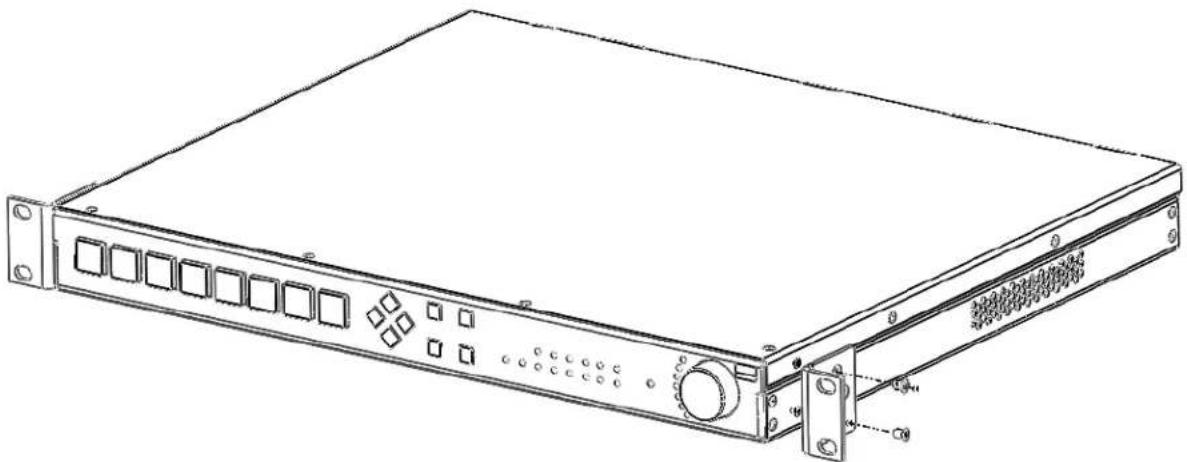
FIG. 5 displays how the brackets should be attached to the NCITE-813/813A:
natural_image
Line drawing of a server rack with ports and connectors (no text or symbols)FIG. 5 Rack Mounting the NCITE-813/813A
- Install the presentation system in the mounting rack by using the mounting screws to affix the unit to the rack. Use four screws to mount each bracket on the NCITE-813AC. The NCITE-813/813A requires only two screws for each bracket.
NOTE: You can also rotate the mounting brackets on each type of unit to mount the device to the underside of a surface such as a table or desk.
- Connect any applicable wires to the presentation system. Refer to the Wiring and Device Connections (Incite Devices) section on page 22 for wiring diagrams and pinout descriptions.
CAUTION: DO NOT stand other units directly on top of the presentation system when it is rack mounted, as this will place excessive strain on the mounting brackets.
Ventilation
ALWAYS ensure that the rack enclosure is adequately ventilated. Do not block any ventilation openings. Sufficient airflow must be achieved (by convection or forced-air cooling) to satisfy the ventilation requirements of all the items of equipment installed within the rack.
NOTE: The maximum operating ambient temperature is 40C (104F).
CAUTION: When installing equipment into a rack, distribute the units evenly. Otherwise, hazardous conditions may be created by an uneven weight distribution.
Reliable earthing (grounding) of rack-mounted equipment should be maintained.
The presentation system should not be installed in enclosed spaces. It is recommended that you leave 1 RU of space above the presentation system when you install it in a rack.
Wiring and Device Connections
Overview
This chapter provides functional details for each item on the front and rear panel of the Incite Presentation Systems. Wiring specifications are also provided, when applicable. FIG. 6 displays the front panel of the NCITE-813.
MENU ON/OFF

FIG. 6 NCITE-813 front panel
FIG. 7 displays the rear panel of the NCITE-813:

FIG. 7 NCITE-813 rear panel
The NCITE-813A features the same options on the rear panel as the NCITE-813 with the exception of also featuring 2 AMP OUT captive-wire connectors.
FIG. 8 displays the rear panel of the NCITE-813A.

FIG. 8 NCITE-813A rear panel
The NCITE-813AC features the same options on the rear panel as the NCITE-813A but also features several control ports including RS-232, RS-232/422/485, Relay, I/O, IR/Serial, AxLink, and ICSLAN ports.
FIG. 9 displays the rear panel of the NCITE-813AC.
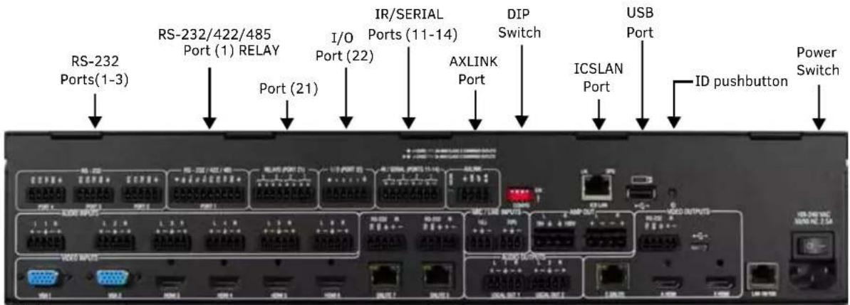
FIG. 9 NCITE-813AC rear panel
FIG. 10 displays the front panel of the NCITE-813AC:

FIG. 10 NCITE-813AC front panel
Front Panel Controls and Indicators
The following sub-sections describe each component on the front panel of the NCITE-813 units. Refer to FIG. 6 on page 26 for the component layout of the front panel.
LEDs (All NCITE units)
This section details the LEDs that appear on the front of all NCITE-813 units.
FIG. 12 displays the front panel LEDs for the NCITE-813:

FIG. 11 Front Panel - HDCP and ACTIVE LEDs
LEDs (NCITE-813AC only)
This section details the LEDs that only are featured on the front panel of the NCITE-813AC.
FIG. 12 displays the front panel LEDs for the NCITE-813AC:

FIG. 12 Front Panel - LEDs
The LEDs on the front panel indicate the communications status of several different connections, as described in the following table:
| Front Panel LEDs | ||
| Label Color Description | ||
| LINK/ACT green Blinks when receiving system is programmed and communicating properly. | ||
| STATUS green Blinks to indicate that the Controller is transmitting data. | ||
| OUTPUT red Blinks to indicate that the Controller is receiving data. | ||
| INPUT yellow Blinks to indicate that the Controller is receiving data. | ||
| ICSLAN | red | Blinks when the category cable to port 1 is connected and terminated correctly. The LED also blinks when receiving LAN data packets. |
| SERIAL (1-4) | red/yellow | 4 sets of LEDs indicate that the RS-232 ports (2-4) and RS-232/422/485 port (1) are transmitting or receiving data.Red = transmitting dataYellow = receiving data |
| RELAYS (1-4) | red | Lights to indicate that one or more of the relay channels (1-4) of port 21 are currently active (closed). |
| IR/SERIAL (1-4) | red | Lights to indicate that one or more of the IR/Serial channels (1-4) of ports 11-14 are currently transmitting control data. |
| I/O (1-4) | yellow | Lights to indicate that one or more of the I/O channels (1-4) of port 22 are currently active. |
General Status LEDs
The General Status LEDs include the Link/Activity, Status, Output, and Input LEDs.
FIG. 13 displays the General Status LEDs on the NCITE-813AC.

FIG. 13 General Status LEDs
- Link/Act - Lights green when the link is up and toggles off when a data packet is sent or received.
- Status - Lights green and blinks once per second if the master is functioning normally and has established communication with a DHCP server.
- Output - Lights red when the controller transmits data
- Input - Lights yellow when the controller receives data
The following table lists the following special LED patterns for the Link/Act and Status LEDs:
| LED Patterns | ||
| Mode Link/Act Status | ||
| Normal ON if connected to the Master, blinks off on | receiving data | Blinks as instructed by NetLinx BLINK message. ON solid if offline with Master. |
| Normal Boot (DHCP found)NOTE: This state continues from the time an IP address is obtained until the device is online with the Master. | OFF ON | |
| Normal Boot (DHCP, no server)NOTE: This state continues until a valid IP address is obtained. | Fast Blink*, then normal operation ON | |
| Normal Boot (Static IP)NOTE: This state continues until the device finishes the initialization sequence. | OFF until connected to Master Fast Blink (through initialization sequence), then ON until first blink from Master. | |
| Boot with ID Pushbutton held down Slow Blink (1Hz) Slow Blink (1Hz) | ||
| ID Pushbutton held down long enough for reset to default parameters | Fast Blink* until ID Pushbutton is released, then OFF | Fast Blink* until ID Pushbutton is released, then OFF |
| ID Pushbutton held down long enough for reset to default firmware image | Solid ON, transitions to OFF once the unit completes writing to flash and is ready to reboot | Solid ON, transitions to OFF once the unit completes writing to flash and is ready to reboot |
| In Auto ID mode Normal Blink (2Hz) | ||
| ID Pushbutton held down long enough to accept new ID | 2 Blinks, then normal 2 Blinks, then normal | |
| After boot: ID Pushbutton held down, but not long enough for IP mode change | Slow Blink (1Hz) Slow Blink (1Hz) | |
| After boot: ID Pushbutton held down long enough for IP mode change | Fast Blink*, then OFF Fast Blink*, then OFF | |
| Downloading firmware | Fast Blink*, alternating with Status LED | Fast Blink*, alternating with Link/Act LED |
ICSLAN LEDs
The ICSLAN LED lights green when there is an active link on the ICSLAN port. The light toggles off when a data packet is sent or received (see FIG. 14).

FIG. 14 ICSLAN LEDs
SERIAL LEDs
The SERIAL LEDs are two sets of LEDs which light to indicate that the RS-232 ports are transmitting or receiving RS-232, 422, or 485 data (red= TX, yellow = RX). The light toggles on when a data packet is sent or received. There are two sets of four SERIAL LEDs on the NCITE-813AC (see FIG. 15).

FIG. 15 SERIAL LEDs
RELAYS LEDs
The RELAYS LEDs light red to indicate that the corresponding relay port is active. The light toggles off when the relay port is not engaged. There are four RELAY LEDs on the NCITE-813AC (see FIG. 16).

FIG. 16 RELAYS LEDs
IR/SERIAL LEDs
The IR/SERIAL LEDs light red to indicate that the corresponding IR/Serial port is transmitting data. There are four IR/SERIAL LEDs on the NCITE-813AC (see FIG. 17).

FIG. 17 IR/SERIAL LEDs
I/O LEDs
The I/O LEDs light yellow to indicate that the corresponding I/O port is active. There are four I/O LEDs on the NCITE-813AC (see FIG. 18).

FIG. 18 I/O LEDs
Video Input Selection (1-8)
The eight backlit Video Input Selection buttons (1-8) allow you to select an active video input (see FIG. 19).

FIG. 19 Video Input Selection
Each numbered VIDEO INPUT SELECTION button is associated with the corresponding numbered Input on the rear panel (refer to FIG. 7 on page 26):
| Video Input Selection Options | |
| Video Input Selector | Corresponding Input Connector |
| Input 1 VIDEO INPUT | 1 (VGA connector) |
| Input 2 VIDEO INPUT | 2 (VGA connector) |
| Input 3 VIDEO INPUT | 3 (HDMI connector) |
| Input 4 VIDEO INPUT | 4 (HDMI connector) |
| Input 5 VIDEO INPUT | 5 (HDMI connector) |
| Input 6 VIDEO INPUT | 6 (HDMI connector) |
| Input 7 DXLITE VIDEO | INPUT 7 (RJ-45 connector) |
| Input 8 DXLITE VIDEO | INPUT 8 (RJ-45 connector) |
Navigation Pushbuttons
The four directional navigation buttons (Left/Right/Up/Down) enable you to navigate through and adjust the configurable parameters shown on the On-Screen menu (OSM). The UP and DOWN navigation buttons are used to move between configurable parameters within a menu. Pressing UP takes you to the previous configuration parameter. Pressing DOWN takes you to the next configuration parameter. These buttons do not change the currently selected menu. The LEFT and RIGHT navigation buttons are used to change the setting of the displayed parameter. If the parameter is read-only the value cannot change. Pressing LEFT decreases the value displayed if the setting is numeric, or goes to the previously set item if the setting is a set selection. Pressing RIGHT increases the value displayed if the setting is numeric, or goes to the next set item if the setting is a set selection. These buttons do not change the currently selected menu. FIG. 20 displays the navigation pushbuttons.
Move up to next menu configuration parameter

flowchart
graph TD
    A["Decrease value, or change the state of the selected parameter"] --> B["Device with four diamond-shaped indicators"]
    C["Increase value, or change the state of the selected parameter"] --> B
    D["Move down to next menu configuration parameter"] --> B
FIG. 20 Navigation Pushbuttons
MENU ON/OFF Pushbutton
Press the MENU ON/OFF pushbutton to access the SWITCH menu on the OSM. Press this button to configure the audio or video inputs and outputs.
FIG. 21 displays the MENU ON/OFF pushbutton.
FIG. 21 MENU ON/OFF Pushbutton
SELECT Pushbutton
Press the SELECT pushbutton to select and configure video or audio parameters. This button does not access the menus or change the currently selected menu. FIG. 22 displays the SELECT pushbutton.

FIG. 22 SELECT Pushbutton
VIDEO MUTE Pushbutton
Press the VIDEO MUTE button to enable or disable video on all output displays.
FIG. 23 displays the VIDEO MUTE pushbutton.

FIG. 23 VIDEO MUTE Pushbuttons
The pushbuttons light (red) to indicate that Video muting is active.
MODE Pushbutton
Press the MODE pushbutton is reserved for future use.
FIG. 24 displays the MODE pushbutton.

FIG. 24 MODE Pushbutton
Program Port (NCITE-813AC only)
The front panel of the NCITE-813AC features one Type-B USB port for connecting the controller to a PC via USB cable. The Program port uses a standard Type-A-to-Type-B USB cable to connect to a PC. When connected, you can view your NCITE-813AC among the listed Masters connected via USB in NetLinx Studio. See the Initial Configuration chapter in the NX-Series Controllers WebConsole and Programming Guide for more information.

FIG. 25 Program port
USB Port (NCITE-813AC only)
The front panel of the NCITE-813AC features one Type-A USB port you can use to connect a mass storage device for loading .tkn files, reading or writing configuration files and log files, or updating the firmware on the unit.
NOTE: This USB port only supports a FAT32 file system.
This USB port (FIG. 26) uses standard USB cabling to connect to any mass storage or peripheral devices.
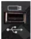
FIG. 26 USB port
NOTE: USB hubs are not supported on this port.
Rear Panel Inputs and Outputs
The following sub-sections describe each component on the rear panel of the Digital Video Presentation Systems. Refer to FIG. 7 on page 26 for the component layout of the rear panel.
VIDEO INPUTS (1-8)
The VIDEO INPUTS area on the rear panel consists of eight video ports including 2 VGA ports, 4 HDMI ports, and 2 DXLITE ports. FIG. 27 displays the VIDEO INPUTS ports.

FIG. 27 VIDEO INPUTS ports
The following sections provide more details for each type of input port.
VGA INPUTS (1-2)
The NCITE-813AC features two HD-15 VGA connectors for RGBHV video input. These connectors are used to accept a variety of analog video signals from a source device. These ports support standard VGA cables and standard HD-15 to RCA component cables (FG10-2170-03). The following table provides cable pinout details for HD-15 connections for VGA, component, S-Video, and composite.
| VGA INPUT Connector Cable Pinouts | ||||
| Input Pin # V | VGA-RGBHV Component S-Video Composite | |||
| 1 Red Pr | n/c n/c | |||
| 2 Green | Y Y Composite | |||
| 3 Blue Pb | C | n/c | ||
| 4 n/c | n/c | n/c n/c | ||
| 5 GND | n/c | n/c n/c | ||
| 6 GND - | Red GND -Pr | n/c n/c | ||
| 7 | GND - Green | GND - Y | GND - Y | GND - Composite |
| 8 GND - | Blue GND -Pb | GND - C | n/c | |
| 9 +5 V | DDC n/c | n/c | n/c | |
| 10 | GND n/c | n/c | n/c | |
| 11 | n/c | n/c | n/c | n/c |
| 12 | DDC_SDA | n/c | n/c | n/c |
| 13 | H Sync | n/c | n/c | n/c |
| 14 | V Sync | n/c | n/c n/c | |
| 15 | DDC_SCL | n/c | n/c | n/c |
FIG. 28 displays the location of the pins for each VGA input.

FIG. 28 Pinout table and HD-15 receptacle pins on NCITE-813AC
HDMI INPUTS (3-6)
The HDMI INPUT connectors on the rear panel are used to connect source input devices to the presentation system. The presentation system routes digital video and audio from connected source input devices to the connected output devices. These ports support HDMI (with Deep Color) and HDCP 2.2.
NOTE: When an input sends protected content to a non-HDCP compliant monitor, the video output displays a black screen rather than a red screen as displayed via Enova DVX Presentation Switchers.
These inputs support 2 CH L-PCM.
The following table describes the pinout configuration of the HDMI INPUTS connectors:
| HDMI INPUT Connectors - Pinouts and Signals | |||
| Pin Signal Pin Signal | |||
| 1 TMDS Data 2+ 11 TMDS Clock Shield | |||
| 2 TMDS Data 2 Shield 12 TMDS Clock- | |||
| 3 TMDS Data 2- 13 CEC | |||
| 4 TMDS Data 1+ 14 Reserved, HEC Data | |||
| 5 TMDS Data 1 Shield 15 SCL | |||
| 6 TMDS Data 1- 16 SDA | |||
| 7 TMDS Data 0+ 17 DDC/CEC/HEC Ground | |||
| 8 TMDS Data 0 Shield 18 +5V Power (max 50mA) | |||
| 9 TMDS Data 0- 19 Hot Plug Detect, HEC Data+ | |||
| 10 | TMDS Clock+ | ||
FIG. 29 displays the pin locations for the HDMI pinouts:

FIG. 29 HDMI pinouts
To connect HDMI input source devices (DVI and HDMI) to the HDMI INPUT connectors, the following (optional) adapter cables are required:
| DVI Input Adapter Cables | |||
| Name | Description | Length | FG# |
| HDMI Interface Cable | HDMI Male to HDMI Male | 6 1/2' (2m) | FG10-2178-05 |
| HDMI to DVI Cable | HDMI Male to DVI Male | 6' (1.828m) | FG10-2179 |
DXLITE INPUTS (7-8)
Two DXLite (RJ-45) connectors transport digital video, embedded audio, and bi-directional control over twisted pair cable to DXLink devices or boards, including digitally transcoded analog video signals. Both inputs support HDCP 2.2.
NOTE: When an input sends protected content to a non-HDCP compliant monitor, the video output displays a black screen rather than a red screen as displayed via Enova DVX Presentation Switchers.
AUDIO INPUTS (1-6)
The AUDIO INPUTS connectors are 3.5 mm 5-position captive-wire terminals that can be wired for either balanced (differential) or unbalanced (single-ended) stereo audio. Since the NCITE allows independent switching of video and audio, video and audio inputs of the same number do not have to be connected to the same source equipment. These connectors feature the following specifications:
- Nominal input level: +4 dBu (1.228 Vrms) balanced or -10 dBu (0.3262 Vrms) unbalanced
• Maximum input level: 2 Vrms - Input impedance: >12k ohms unbalanced, >12k ohms balanced, DC coupled FIG. 30 displays the AUDIO INPUTS connectors.

FIG. 30 AUDIO INPUTS connectors
Source devices require either balanced (differential) or unbalanced (single-ended) connections. FIG. 31 illustrates options for wiring between sources and input connectors. More than one option can be used in the same system.

Balanced wiring
Presentation System
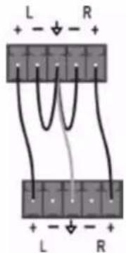
Unbalanced wiring
FIG. 31 Stereo 5-terminal wiring
FIG. 32 provides details for wiring from an audio input to an unbalanced source device that has RCA connectors. Positive and ground wires connect to the source. You also can use a CC-3.5ST5-RCA2F 2 RCA Female to 5-Pin Phoenix Cable (FG10-003-20) for this type of connection.

FIG. 32 RCA Stereo audio source wiring
CAUTION: Do not connect the negative terminals to the source connector. Doing so can cause damage to your device.
MIC/LINE INPUTS
Two 3.5mm 3-pin captive-wire MIC/LINE INPUT connectors allow up to two mono microphones to be connected to the presentation system. Each microphone input supports balanced and unbalanced audio. Each input supports up to 48V of phantom power. FIG. 33 displays the MIC/LINE INPUTS connectors.

FIG. 33 MIC/LINE INPUTS
FIG. 34 illustrates wiring connections between the presentation system and a mono RCA output and an XLR output.
NCITE NCITE

RCA output

XLR output
FIG. 34 RCA (mono) and XLR output wiring
FOR INCITE VERSIONS WITH AMPLIFIER (FG1901-12, FG1901-16):

CAUTION: Never use shielded cable for output wiring.

CAUTION: Never connect the speaker return to the chassis of the Incite, or damage to the device may result.

NOTE: Custom wiring should only be performed by qualified personnel. Class 2 output wiring is required.
AMP OUT
The AMP OUT amplified audio outputs are available only on the NCITE-813A and NCITE-813AC, and each model offers two separate wiring options:
- The 4-position captive wire connector provides amplified, variable, mono or stereo audio output.
- The two 2-position captive wire connectors provide 70V or 100V mono amplified audio output. Connect a speaker to either the 70V or 100V terminal, but not both simultaneously. FIG. 35 displays the AMP OUT audio output.

FIG. 35 AMP OUT CLASS 2 WIRING Output
For standard 8-Ohm speaker loads, connect speakers to the AMP OUT output as displayed in FIG. 36.

FIG. 36 Connecting speakers to the Amplified Audio output
For mono amplified output, connect a speaker to either the 70V or 100V terminals as displayed in FIG. 37.

FIG. 37 Connecting speakers to the Amplified Audio output (-T models)
AUDIO OUTPUTS
The Line Level audio outputs (ports 1-2) provide balanced or unbalanced, mono or stereo line-level audio output. FIG. 38 displays the AUDIO OUTPUTS connectors,

Destination devices require either balanced (differential) or unbalanced (single-ended) connections. FIG. 39 illustrates options for wiring between output connectors and the destinations.
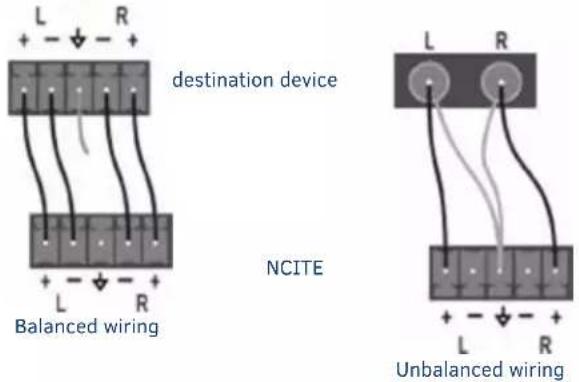
FIG. 39 Stereo 5-terminal wiring
CAUTION: Do not connect the negative terminals to the source connector. Doing so can cause damage to your device.
Rear Panel Control and Power (NCITE-813AC only)
The following sub-sections describe the control and power components on the rear panel of the NCITE-813AC. These components are not featured on the NCITE-813 or NCITE-813A. Refer to FIG. 9 on page 27 for the component layout of the rear panel.
Serial Ports
The NCITE-813AC features device control serial ports that support either RS-232 or RS-232, RS-422, and RS-485 communication protocols. Each port supports the following specifications:
• XON/XOFF (transmit on/transmit off)
• CTS/RTS (clear to send/ready to send)
• 300-115,200 baud rate
RS-232 Ports
The RS-232 ports (ports 2-4 on the NCITE-813AC) are 5-pin 3.5 mm male connectors used for connecting A/V sources and displays. These ports support most standard RS-232 communication protocols for data transmission.
FIG. 40 displays the RS-232 ports for the NCITE-813AC.
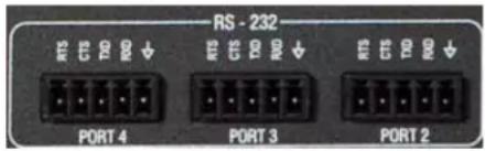
FIG. 40 RS-232 ports
The following table lists the pinouts for the RS-232 ports.
| RS-232 Port Pinouts | |
| Pin 1 GND | |
| Pin 2 RXD | |
| Pin 3 TXD | |
| Pin 4 CTS | |
| Pin 5 RTS | |
In the above table, pin 1 is located on the right side of the port, and the pinouts count up to the left.
RS-232/422/485 Port
The RS-232/422/485 port (port 1) is a 10-pin 3.5 mm male connector used for connecting A/V sources and displays. This port can be used as a RS-232 port by disabling RS-422 and RS-485 on the ports. By default, RS-422 and RS-485 are disabled on this port. Only with RS-422/485 disabled will the ports operate as RS-232. See the SET BAUD command and the TSET BAUD command in the NetLinx Programming chapter of the NX-Series Controllers WebConsole and Programming Guide for more information on enabling and disabling RS-422 and RS-485 on these ports. These ports support most standard RS-232, RS-422, and RS-485 communication protocols for data transmission.
FIG. 41 displays the RS-232/422/485 port for the NCITE-813AC.

FIG. 41 RS-232/422/485 ports
The following table lists the pinouts for the RS-232/422/485 port.
| RS-232/422/485 Port Pinouts | |
| Pin 1 GND (used | in RS-232 and RS-422) |
| Pin 2 RXD (used | In RS-232) |
| Pin 3 TXD (used | in RS-232) |
| Pin 4 CTS (used | in RS-232) |
| Pin 5 RTS (used | in RS-232) |
| Pin 6 TX+ (used | in RS-422 and RS-485) |
| Pin 7 TX- (used | in RS-422 and RS-485) |
| Pin 8 RX+ (used | in RS-422 and RS-485) |
| Pin 9 RX- (used | in RS-422 and RS-485) |
| Pin 10 +12V | |
In the above table, pin 1 is located on the right side of the port, and the pinouts count up to the left.
Relay Port
The relay port (port 21 on the NCITE-813AC) is an 8-pin 3.5 mm male connector used for connecting external relay devices. You can connect up to 4 independent external relay devices on the NCITE-813AC. When a relay is "OFF", terminals A and B are open-circuit. When a relay is "ON", terminals A and B are shorted together.
Relay Connections
Use connectors A for common and B for output (FIG. 42). Each relay is isolated and normally open.
A metal connector strip is also provided to common multiple relays.

FIG. 42 RELAY connector (male)
- 8-channel single-pole single-throw relay ports
• Each relay is independently controlled
• Supports up to 4 independent external relay devices
• Channel range = 1-8
• Each relay can switch up to 24 VDC or 28 VAC peak @ 1 A - One 8-pin 3.5mm male connector provides relay termination
I/O Port
The I/O port (port 22 on the NCITE-813AC) is a 6-pin 3.5 mm male connector used for connecting logic-level outputs. The I/O port responds to either switch closures, voltage level (high/low) changes, or it can be used for logic-level outputs. Each port is capable of being used as an input or an output.
FIG. 43 displays the I/O port for the NCITE-813AC.

FIG. 43 I/O ports
- A contact closure between the GND and an I/O port is detected as a Push.
- When used for voltage inputs, the I/O port detects a low signal (0 - 1.5 VDC) as a Push, and a high signal (3.5 - 5 VDC) as a Release. (This I/O port uses 5V logic but can handle up to 12V without harm).
- When used for outputs, the I/O port acts as a switch to GND and is rated for 200mA @ 12 VDC.
• The NCITE-813AC can use up to 4 I/O ports - The PWR pin provides +12 VDC @ 200 mA and is designed as a power output for the PCS Power Current Sensors, VSS2 Video Sync Sensors (or equivalent).
- The GND connector is a common ground and is shared by all I/O ports. A common ground is shared with I/O ports 1-4.
- The input impedance on the I/O port is 22k.
| I/O Port Wiring Specifications | |
| Pin Signal Function | |
| 1 GND Signal GND | |
| 2 I/D 1 Input/Output | |
| 3 I/D 2 Input/Output | |
| 4 I/D 3 Input/Output | |
| 5 I/D 4 Input/Output | |
| 6 12 VDC PWR |
In the above table, pin 1 is located on the right side of the port, and the pinouts count up to the left.
IR/SERIAL Port: Connections and Wiring
The IR/SERIAL ports provide IR transmit/one-way serial connections that support high-frequency carriers up to 1.142 MHz. You can simultaneously generate up to four IR/Serial data signals on the NCITE-813AC.
These ports accept an IR Emitter (CC-NIRC) that mounts onto the device's IR window, or a mini-plug (CC-NSER) that connects to the device's control jack. You can also connect a data 0 - 5 VDC device to these ports. FIG. 44 displays the IR/SERIAL ports for the NCITE-813AC.

FIG. 44 IR/SERIAL connector (male)
NOTE: The maximum baud rate for ports using DATA mode is 19200. Also, DATA mode works best when using a short cable length (< 10 feet).
NOTE: For each data signal, the negative (-) terminal is for Signal GND, and the positive (+) terminal is for IR/Serial data.
The IR/Serial connector wiring specifications are listed in the following table.
| IR/SERIAL Connector Wiring Specifications (per Port) | |
| Signal # NCITE-813AC | Port # |
| 1 | 11 |
| 2 | 12 |
| 3 | 13 |
| 4 | 14 |
AxLink Port and LED (4-pin captive-wire)
The AxLink port allows the central controller to support AMX AxLink devices.
FIG. 45 displays the AXLINK port for the NCITE-813AC.

FIG. 45 AxLink Ports and LEDs
The (green) AxLink LED indicates AxLink data activity:
- Off - No power, or the controller is not functioning properly.
- 1 blink per second - Normal operation.
- 3 blinks per second - AxLink bus error. Check all AxLink bus connections.
The AxLink port can be used to supply power to downstream AxLink-compatible devices as long as the maximum current draw is less than 0.5 Amps on the NCITE-813AC. To isolate the central controller from high in-rush current, AxLink devices, or potential power faults on the AxLink bus, it is strongly recommended that you power external AxLink devices from an independent power supply.
NOTE: The AxLink port provides only limited power to connected AxLink devices. It is recommended to use an alternate power source when connecting AxLink devices to the central controller.
IMPORTANT: The NCITE-813AC CANNOT be powered via the AxLink port. The +12V pin on the AxLink connectors are designed only for voltage output. Do NOT connect +12V from a power supply or the NXA-PDU to the +12V pin on the AxLink connectors, or you may permanently damage the NCITE-813AC and/or the power supply.
Refer to the following table for the wiring length information used with the AxLink port:
| Wiring Guidelines | |
| Wire size Maximum wiring length | |
| 18 AWG 154.83 feet (47.19 meters) | |
| 20 AWG 98.30 feet (29.96 meters) | |
| 22 AWG 63.40 feet (19.32 meters) | |
| 24 AWG 38.68 feet (11.79 meters) |
FIG. 46 provides wiring requirements for the AxLink connector:
To the Controller's AxLink/PWR connector To the external AxLink device
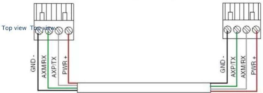
FIG. 46 Mini-Phoenix connector wiring diagram (direct data and power)
To use the 4-pin 3.5 mm mini-Phoenix (male) captive-wire connector for data communication and power transfer, the incoming PWR and GND cable from the 12 VDC-compliant power supply must be connected to the AxLink cable connector going to the central controller. FIG. 47 shows the wiring diagram:

FIG. 47 4-pin mini-Phoenix connector wiring diagram (using external power source)
CAUTION: When you connect an external power supply, do not connect the wire from the PWR terminal (coming from the external device) to the PWR terminal on the Phoenix connector attached to the Controller unit. Make sure to connect only the AXM, AXP, and GND wires to the Controller's Phoenix connector when using an external power supply.
Make sure to connect only the GND wire on the AxLink/PWR connector when using a separate 12 VDC power supply. Do not connect the PWR wire to the AxLink connector's PWR (+) opening.
Configuration DIP Switch
The NCITE-813AC has a configuration DIP switch which allows for certain operations to occur during boot-time. FIG. 48 displays the Configuration DIP Switch for the NCITE-813AC.
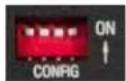
FIG. 48 Configuration DIP Switch
Program Run Disable (PRD) Mode
You can use the Configuration DIP switch to set the on-board Master to Program Run Disable (PRD) mode. PRD mode prevents the NetLinx program stored in the on-board Master from running when you power up the Integrated Controller. You should only use PRD mode when you suspect the resident NetLinx program is causing inadvertent communication and/or control problems. If necessary, place the on-board Master in PRD mode and use the NetLinx Studio program to resolve the communication and/or control problems with the resident NetLinx program. Then download the new NetLinx program and try again. FIG. 49 displays the default DIP switch settings and the settings for PRD mode. To switch to PRD mode, move the position 1 DIP switch to ON.


Default mode PRD mode
FIG. 49 DIP Switch settings - PRD mode
NOTE: Consider equating PRD Mode to a PC?s SAFE Mode setting. With PRD mode, you can continue to power a unit, update the firmware, and download a new program while circumventing any problems with a currently downloaded program. You must power cycle the unit after activating/deactivating PRD mode on Program Port DIP switch #1.
ICSLAN Port
The NCITE-813AC has two types of Ethernet ports: LAN and ICSLAN. The LAN port is used to connect the master to an external network, and the ICSLAN port is used to connect to other AMX equipment or third-party A/V equipment. The ICSLAN port provides Ethernet Communication to connected AMX Ethernet Equipment in a way that is isolated from the primary LAN connection. The ICSLAN port is a 10/100 Port RJ-45 connector and Auto MDI/MDI-X enabled. The NCITE-813AC features one port. The port supports IPv4 and IPv6 networks, as well as HTTP, HTTPS, Telnet, and FTP.

FIG. 50 ICSLAN port
The ICSLAN port gets its IP addresses in one or more of the following ways:
- IPv4 - Static assignment of the subnetwork address by the user
• IPv6 - Link local address
Using the ICSLAN Network
The default IP address for the ICSLAN network is 198.18.0.1 with a subnet mask of 255.255.0.0.
It is important that the ICSLAN and LAN subnets do not overlap. If the LAN port is configured such that its address space overlaps with the ICSLAN network, the ICSLAN network will be DISABLED.
NOTE: Typically, the NCITE-813AC communicates with an A/V switcher via ICSLAN. Since the A/V switcher has a static IP address on the ICSLAN network, and you cannot change the IP address on the switcher, you cannot change the 198.18 subnet information on the NCITE-813AC platform of processors. You can only change the Host name and DHCP server settings.
DHCP Server
The ICSLAN port has a built-in DHCP server. This DHCP server is enabled by default and will serve IP addresses to any connected devices set to DHCP mode.
The DHCP server can be disabled from telnet with the command:
SET ICSLAN
The DHCP address range is fixed. The server will provide addresses in the range x.x.0.2 through x.x.63.255.
Devices using static IP addresses on the ICSLAN network should be set within the reserved static IP address range of x.x.64.1 to x.x.255.255.
Opening LAN and ICSLAN Sockets from Code
When opening sockets from NetLinx or Java code there is no mechanism to indicate which network to use. The controller will open the socket on whichever network has an IP subnet that matches the address provided in the command to open the socket. There is no indication which network was used, only whether the socket was created successfully.
USB Port
The NCITE-813AC features one Type-A USB port you can use to connect a mass storage device for loading .jar files and IR data files (.irl), reading or writing configuration files and log files, or updating the firmware on the unit.
NOTE: This USB port only supports a FAT32 file system.
This USB port (FIG. 51) uses standard USB cabling to connect to any mass storage or peripheral devices.

FIG. 51 USB port
NOTE: USB hubs are not supported on this port.
ID Pushbutton
The NCITE-813AC features an ID pushbutton which you can use to toggle between static and dynamic IP addressing. You can also use the pushbutton to reset the default settings on the controller or restore the controller to its factory firmware image.
FIG. 52 displays the ID pushbutton for the NCITE-813AC.

FIG. 52 ID pushbutton
Switching to Static or Dynamic IP Addressing
To toggle between static or dynamic IP addressing, the controller cannot be currently booting or it must be in ID Mode. If these conditions are met, holding the ID pushbutton for 10 seconds toggles the current IP addressing mode between static and dynamic IP addressing.
Restoring the Controller Settings to the Factory Defaults
To restore the controller settings to the factory defaults, the controller must be currently booting and you must press the ID push-button for 10 seconds. The controller is booting when the System and Input LEDs are both ON and the Output LED is OFF. This includes resetting the static IP address to its default and deleting the NetLinx program.
NOTE: The presentation system cannot detect a press of the ID pushbutton until 30 seconds into the booting process. While booting the unit, any ID pushbutton presses before 30 seconds have elapsed are not detected. You can verify the unit has detected a button press when the front panel LEDs begin to flash at one second intervals.
CAUTION: Pressing the ID pushbutton for 20 seconds restores the factory firmware image on the controller. Do not press the pushbutton significantly longer than the necessary 10 seconds if you only want to restore the default settings on the controller.
Restoring the Controller's Factory Firmware Image
To restore the controller's factory firmware image, the controller must currently be booting and you must press the ID pushbutton for 20 seconds. This also deletes all code and IRL files.
NOTE: The presentation system cannot detect a press of the ID pushbutton until 30 seconds into the booting process. While booting the unit, any ID pushbutton presses before 30 seconds have elapsed are not detected. You can verify the unit has detected a button press when the front panel LEDs begin to flash at one second intervals.
LAN 10/100 Port
The NCITE-813 features a LAN 10/100 port to provide 10/100 Mbps communication via Category cable. This is an Auto MDI/MDI-X enabled port, which allows you to use either straight-through or crossover Ethernet cables. The port support IPv4 and IPv6 networks, as well as HTTP, HTTPS, SSH, and FTP.
The LAN port automatically negotiates the connection speed (10 Mbps or 100 Mbps), and whether to use half duplex or full duplex mode.
FIG. 53 displays the LAN port for the NCITE-813.

FIG. 53 LAN 10/100 port
FIG. 54 provides the pinouts and signals for the LAN connector and cable.

flowchart
graph LR
    A["End A"] --> B["White/Orange Stripe"]
    A --> C["Orange"]
    A --> D["White/Green Stripe"]
    A --> E["Blue"]
    A --> F["White/Blue Stripe"]
    A --> G["Green"]
    A --> H["White/Brown Stripe"]
    A --> I["Brown Stripe"]
    B --> J["1"]
    C --> K["2"]
    D --> L["3"]
    E --> M["4"]
    F --> N["5"]
    G --> O["6"]
    H --> P["7"]
    I --> Q["8"]
    J --> R["End B"]
FIG. 54 RJ-45 wiring diagram
FIG. 55 describes the blink activity for the LAN connector and cable.

FIG. 55 LAN connector / LEDs
The LAN port gets its IP address(es) in one or more of the following ways:
IPv4
• Static assignment by the user
• Dynamic assignment by an IPv4 DHCP server
- Link local as a fall back when configured for DHCP but unable to successfully obtain an address
IPv6
- Link local address
- Prefix(es) assigned by a router
Power Connector/Switch
FIG. 56 displays the power switch and connector for the NCITE-813AC.

←Power switch
Power cable connector
FIG. 56 Power Connector/Switch/Fuse
CAUTION: This unit should only have one source of incoming power. Using more than one source of power to the device can result in damage to the internal components and a possible burn out. Apply power to the unit only after installation is complete.
Audio/Video Configuration
Overview
You can access the configuration settings for the Digital Video Presentation System by using one of the following methods:
• Using the on-screen menu
• Using the WebConsole via a Web browser (see page 52)
Using the On-Screen Menu
You can access the configuration settings for the presentation system by using the MENU ON/OFF button on the front panel of the device. FIG. 57 displays the on-screen menu.

FIG. 57 On-Screen menu
Use the Navigational buttons to traverse the available configuration parameters and change their settings. FIG. 58 displays the navigational function of each button.
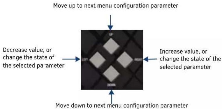
FIG. 58 Navigation buttons
Press the SELECT pushbutton to select the highlighted setting on the on-screen menu and use the navigational buttons to peruse the available options for that setting or increase/decrease the value of the setting.
When navigating the on-screen menu, you can change the setting of any option that appears blue when highlighted. Any option that appears gray cannot be altered. Any option featuring a guillemet (>) indicates that the option contains one or more sub-options. Use the right navigational button to view the sub-options. Pressing the MENU ON/OFF button a second time closes the on-screen menu.
NOTE: The on-screen menu may appear pixelated when downscaling video at lesser resolutions.
Audio Settings
Press the MENU ON/OFF button on the front panel of the presentation system to access the on-screen menu and the Audio settings. The Audio settings appear as default when you access the on-screen menu. The following table lists the audio options available for inputs on the on-screen menu:
| Audio Settings - Inputs Menu Options | |
| INPUTS/OUTPUTS I-8 | |
| Input Name Displays the name of the audio input. This option is view-only. | |
| Stereo | Use the left and right navigational buttons to select a group of preset equalizer settings. You can choose from Enable or Disable. |
| Input Gain | Use the left and right navigational buttons to adjust the gain/attention level of the audio Input. You can set the gain from -24 to +24dB in 1dB Increments. The default setting is 0. |
| Analog Audio | Use the left and right navigational buttons to change the audio format of the selected audio Input. You can choose from Enable or Disable. |
| Test Tone Enable | Use the left and right navigational buttons to enable or disable the test tone set for the selected audio output. This option is only available for audio outputs. |
| Test Tone Generator | Use the left and right navigational buttons to select a test tone for the selected audio output. You can choose from Off, 60Hz, 250Hz, 400Hz, 1kHz, 3kHz, 5kHz, 10kHz, Pink Noise, and White Noise. This option is only available for audio outputs. |
| MICROPHONE | |
| Mic Mode | Use this option to switch between Single Stereo and Dual Mono microphone modes. Select Single Stereo to adjust both microphone inputs or Dual Mono Mode to adjust the microphone settings individually. See the Changing the Microphone Mode section on page 47 for information on how to the change the microphone mode. |
| Single Stereo | Use the left and right navigational buttons to set the mix level of microphone 1 in the overall mix. You can set the mix level from 0 to -100. The default setting is 0. |
| Enable | Use the left and right navigational buttons to toggle whether the selected microphone is active. You can choose from Off or On. The default setting is Off. |
| Phantom Power | Use the left and right navigational buttons to turn on or turn off phantom power for the selected microphone. You can set the Phantom Power to On or Off. The default setting is Off. |
| Preamp Gain | Use the left and right navigational buttons to adjust the preamp gain level of the microphone Input. You can set the gain from 0 to +65dB in 1dB Increments. The default setting is 0. |
| Dual Mono | Use the left and right navigational buttons to adjust the maximum volume of the audio output. You can set the maximum volume from 0 to 100 In Increments of 1. The default value is 100. |
| Enable | Use the left and right navigational buttons to toggle whether the selected microphone is active. You can choose from Off or On. The default setting is Off. |
| Phantom Power | Use the left and right navigational buttons to turn on or turn off phantom power for the selected microphone. You can set the Phantom Power to On or Off. The default setting is Off. |
| Preamp Gain | Use the left and right navigational buttons to Adjust the preamp gain level of the microphone Input. You can set the gain from 0 to +65dB in 1dB Increments. The default setting is 0. |
The following table lists the audio options available for inputs on the on-screen menu:
| Audio Settings - Outputs Menu Options | |
| OUTPUTS 1-8 | |
| Output Name Displays the name of the audio output. This option is view-only. | |
| Volume | Use the left and right navigational buttons to adjust the volume level of the audio output. You can set the level from 0 to -100. |
| Mute | Use the left and right navigational buttons to enable or disable volume muting on the audio output. |
| Test Tone Enable | Use the left and right navigational buttons to enable or disable the test tone set for the selected audio output. |
| Test Tone Generator | Use the left and right navigational buttons to select a test tone for the selected audio output. You can choose from Off, 60Hz, 250Hz, 400Hz, 1kHz, 3kHz, 5kHz, 10kHz, Pink Noise, and White Noise. |
| Audio Group | Displays the audio group this to which the audio output belongs. |
| Amp | The options below appear when you press the right navigation button while this option is highlighted. |
| Volume | Use the left and right navigational buttons to adjust the volume level of the amplifier. You can set the level from 0 to -100. |
| Mute | Use the left and right navigational buttons to enable or disable volume muting on the amplifier. |
| Test Tone Enable | Use the left and right navigational buttons to enable or disable the test tone set for the selected audio output. |
| Test Tone Generator | Use the left and right navigational buttons to select a test tone for the selected audio output. You can choose from Off, 60Hz, 250Hz, 400Hz, 1kHz, 3kHz, 5kHz, 10kHz, Pink Noise, and White Noise. |
| Audio Group Displays the audio group this to which the amplifier belongs. | |
Using the WebConsole, you can create a group of several different audio inputs and outputs and collectively adjust specific settings for the entire group. The following table lists the audio group options available on the on-screen menu.
Audio Settings - Groups Menu Options
| Mix | The options below appear when you press the right navigation button while this option is highlighted. |
| Input | Use the left and right navigational buttons to adjust the mix level of the audio input for the audio group. You can set the level from 0 to -100. |
| Microphone 1 | Use the left and right navigational buttons to adjust the mix level of microphone 1 for the audio group. You can set the level from 0 to -100. |
| Microphone 2 | Use the left and right navigational buttons to adjust the mix level of microphone 2 for the audio group. You can set the level from 0 to -100. |
| Format | Use the left and right navigational buttons to change the audio format of the selected audio input. You can set the audio format to Stereo or Mono. The default setting Is Stereo. |
| Stereo Output Options | The options below appear when you press the right navigation button while this option is highlighted. |
| Mute Use the left and right navigational buttons to mute the audio on all devices in the group. | |
| Volume Use the left and right navigational buttons to adjust the volume levels for all devices in the group. | |
| Balance | Use the left and right navigational buttons to adjust the balance level of the selected audio output. You can set the balance level from -20 to +20. The default value is 0. |
| Sync Delay | Use the left and right navigational buttons to set the number of milliseconds to delay the audio. You can set the delay between 0 to 200 milliseconds. The default value is 32. |
| Mono Output Options | The options below appear when you press the right navigation button while this option is highlighted. |
| Mute Use the left and right navigational buttons to mute the audio on all devices in the group. | |
| Volume Use the left and right navigational buttons to adjust the volume levels for all devices in the group. | |
| Adv. Sup. Feedback | Use the left and right navigational buttons to enable or disable Advanced Suppression Feedback for the audio group. |
Selecting an Audio Test Tone
Selecting a test tone for your input source can help determine if you have your audio devices connected correctly. Perform these steps to select a test tone:
- Press the MENU ON/OFF button on the front panel of the presentation system to open the On-Screen menu.
- With AUDIO highlighted, press the right navigational button to view the audio options.
- Press the down navigational button to select the audio device you want, then press the right navigational button to view its options.
- Press the down navigational button to select OUTPUTS, then press the right navigational button to view its options.
- Press the down navigational button to highlight the Test Tone Generator option.
- Press the SELECT button on the front panel and use the left and right navigational buttons to scroll through the available test tones. Press SELECT again when you see the test tone you want.
- Press the up navigational button to highlight the Test Tone Enable option.
- Press the SELECT button on the front panel and use the left and right navigational buttons to enable the test tone.
Changing the Microphone Mode
Perform these steps to change the microphone mode:
- Press the MENU ON/OFF button on the front panel of the device.
- With the Audio Settings highlighted, press the right arrow button one time to access the Audio settings menu.
- Press the down arrow button until the Microphone option is highlighted, then press the right arrow button to access the Microphone options.
- With Mic Mode selected, press the SELECT button and use the left and right arrow buttons to toggle between Single Stereo and Dual Mono microphones.
- Press the SELECT button to accept the option you want.
Video Settings
Press the MENU ON/OFF button on the front panel of the presentation system to access the on-screen menu and the Video settings. When the on-screen menu appears, use the DOWN navigational button to access the Video settings. The following table lists the video options available on the on-screen menu:.
| Video Settings Options | |
| INPUTS 1-8 | |
| Input Name | The name of the video input. This information is view-only. You can change the input name by using the WebConsole.NOTE: The maximum number of characters allowed for the input name is 32, however, longer names may not be viewable on the OSD. To keep the input name from appearing truncated, the input name should be a maximum of 18 characters. |
| Format The analog format for the video input. You can choose from Stereo or Mono. This information is view-only. | |
| Resolution | The current video resolution and refresh rate for the selected video input. For a complete list of output resolutions, see the DVI and HDMI Supported Output Resolutions section on page 137. This information is view-only. |
| EDID Mode | The type of EDID data to be sent to the source or which output's EDID you would like to mirror to that source. This information is view-only. |
| Preferred EDID | The type of EDID data to be sent to the source or which output's EDID you would like to mirror to that source. This information is view-only. |
| HDCP Compliance | Use the left and right navigational buttons to activate HDCP compliance on the selected input. HDCP compliance is active by default. |
| More Info The options below appear when you press the right navigation button while this option is highlighted. | |
| Color Space This option lists the color space on the video input. This option is view-only | |
| VIC This option lists the VIC on the video input. This option is view-only | |
| V Freq This option lists the video frequency on the video input. This option is view-only | |
| PIP | This option lists whether the input is part of a Picture-in-Picture (PIP) setup. This option is view-only. |
| Color Depth This option lists the color depth on the video input. This option is view-only | |
| Pixel Clock This option lists the pixel clock on the video input. This option is view-only | |
| OUTPUTS | |
| Scaler Setup | Press the right navigational button to access the options for Picture Settings, Scaling Mode, Resolution, and Aspect Ratio. |
| Picture Settings | The options below appear when you press the right navigation button while this option is highlighted. |
| Brightness | Use the left and right navigational buttons to alter the brightness level adjustment applied to all outputs. You can set the brightness level from 0-100. The default setting is 50. |
| Contrast | Use the left and right navigational buttons to alter the contrast level adjustment applied to all outputs. You can set the contrast level from 0-100. The default setting is 50. |
| Scaling Mode | Indicates whether the output image is scaled. This information is view-only. |
| Resolution | The resolution and refresh rate of the selected output. For a complete list of output resolutions, see the DVI and HDMI Supported Output Resolutions section on page 137. This information is view-only. |
| Aspect Ratio | Indicates the aspect ratio and is set to one of the following options:MAINTAIN: Maintains the input aspect ratio while filling the screen either vertically or horizontally. Black bars may appear above and below or to the left and right of the image.STRETCH: Ignores the input aspect ratio and stretches the image to fill the screen in all directions.ZOOM: Maintains the input aspect ratio while zooming the image to fill the screen in all directions. Image data may be lost on the top and bottom or to the left and right of the displayed image.ANAMORPHIC: Use with anamorphic formatted video sources so that images appear correctly on the display.This Information is view-only. |
| Video Settings Options (Cont.) | |
| General Setup Press the right navigational button to access the options for OSD, Video Transition, and Blank/Color Logo. | |
| OSD Press the right navigational button to access the options for OSD. | |
| Enable OSD | Use the left and right navigational buttons to toggle whether you want the On-Screen Display (OSD) overlay to be turned on or off.You can choose from Enabled or Disabled. When enabled, the input name and resolution displays in a small box in the upper left-hand corner of the screen whenever you select a new input source.The location of the input name and resolution can be changed using the OSD Position option. The default setting is Disabled.NOTE: The OSD may appear pixelated when downscaling video at lesser resolutions. |
| OSD Color | Use the left and right navigational buttons to select the background color for the on-screen display. You can choose from Black, White, Yellow, or Blue. The default setting is Black. |
| Allow Display Sleep | Use the left and right navigational buttons to enable or disable sleep delay on the selected video output. |
| Display Sleep Delay | Use the left and right navigational buttons to set the sleep delay for the OSD. |
| OSD Position | Use the left and right navigational buttons to select the on-screen display's relative position so it is unobtrusive to video. You can choose from Top Left, Top Right, Bottom Left, and Bottom Right. The default setting is Top Left. |
| Video Mute | Use the left and right navigational buttons to mute/un-mute (enable/disable) all video output displays. Video mute results in a blank screen on the output displays. |
| Video Freeze | Use the left and right navigational buttons to toggle whether you want the current image to freeze and remain on the screen. You can choose from Enable or Disable. The default setting is Disable. |
| Video Transition | Use the left and right navigational buttons to select a transition between the previously selected video input and the currently selected video input. You can choose from Diag Top Left, Diag Top Right, Diag Bottom Left, Diag Bottom Right, Horiz From Left, Horiz From Right, Vert From Top, Vert From Bottom, and Fade. |
| Blank Color/Logo | Use the left and right navigational buttons to choose a blanking screen. You can choose from Blue, Black, or an uploaded Logo.NOTE: If you have uploaded a logo to display on the output, you can also select the logo from this option. Logo images must be 24-bit color bitmap files at least 36x36 pixels in size. |
| LOCAL HDMI OUTPUT A-B/DXLite OUTPUT CThe following options appear for all three of these outputs unless specified otherwise. | |
| Port This option lists the output port currently being used. This option is view-only. | |
| H ACTIVE This option lists the horizontal active pixels on the video output. This option is view-only. | |
| V ACTIVE This option lists the vertical active pixels on the video output. This option is view-only. | |
| Color Space This option lists the color space on the video output. This option is view-only. | |
| Color Depth This option lists the color depth on the video output. This option is view-only. | |
| VIC | This option lists the VIC on the video output. This option is view-only. |
| Pixel Clock | This option lists the pixel clock on the video output. This option is view-only. |
| Source Channel This option lists the video input currently sending video to the video output. This option is view-only. | |
| DXLite Quality | This option lists the degree or lack of quality in the video output. This option is only available on DXLite Output C and is view-only. |
| WINDOWS: | |
| Windows Settings | Press the right navigational button to view the settings for Window Position, Window Size, Left/Large Input, and Right/ Small Input. |
| Window Position | Use the left and right navigational buttons to choose a window position for the windows when the View Mode is set to Windows. You can choose from Side By Side and Top Bottom. |
| Window Size | Use the left and right navigational buttons to choose a window size for the windows when the View Mode is set to Windows. You can choose from Top Large and Bottom Large. |
| Left/Large Input | Use the left and right navigational buttons to choose a video input for the left window when the View Mode is set to Windows. |
| Right/Small Input | Use the left and right navigational buttons to choose a video input for the right window when the View Mode is set to Windows. |
| PIP Settings | Press the right navigational button to view the settings for PIP Position, PIP Size, Main Window Input, and PIP Window Input. |
| PIP Position | Use the left and right navigational buttons to choose a PIP position for the video output. You can choose from Top Left, Top Right, Bottom Left, and Bottom Right. |
| PIP Size | Use the left and right navigational buttons to choose a PIP size for the video output. You can choose from Small, Medium, and Large. |
| Main Window Input | Use the left and right navigational buttons to choose a video Input for the main window when the View Mode is set to PIP. |
| PIP Window Input | Use the left and right navigational buttons to choose a video input for the PIP window when the View Mode is set to PIP. |
| View Mode | Use the left and right navigational buttons to choose a viewing mode for the video output. You can choose from Transition, PIP, and Window. |
| Video Transition | Use the left and right navigational buttons to choose a video transition mode for the video output. You can choose from Diag Top Left, Diag Top Right, Diag Bottom Left, Diag Bottom Right, Horiz From Left, Horiz From Right, Vert From Top, Vert From Bottom, and Fade In. You can only access this option when the View Mode is set to Transition. |
Network Settings
Press the MENU ON/OFF button on the front panel of the presentation system to access the on-screen menu and the Network settings. When the on-screen menu appears, use the DOWN navigational button to access the Network settings. The following table lists the video options available on the on-screen menu:
Network Menu Options
| IPV4: | |
| DHCP/Static: | Displays how the device is assigned an IP address: either dynamically (DHCP) or manually (Static). This option only appears on NCITE-813/813A models. |
| IP Address: Displays the IP address of the device. | |
| Subnet Mask: Displays the subnet mask of the network. | |
| Gateway: Displays the gateway address of the network. | |
| Hostname: Displays the hostname of the device. | |
| MAC Address Displays the MAC address of the device. | |
| System Number | Displays the system number for the device. |
| IPV6: (These options only appear on NCITE-813/813A models.) | |
| Address 1 | The primary IPv6 address of the device. |
| Address 2 | The secondary IPv6 address of the device. |
| Address 3 | The third IPv6 address of the device. |
| Subnet Mask | The IPv6 subnet mask of the device. |
| Gateway | The IPv6 gateway of the device. |
| NetLinx: (These options only appear on NCITE-813/813A models.) | |
| Device Status | Displays the device status. |
| Master Mode | Displays the Master mode. |
| IP/URL | Displays the IP address/URL of the device. |
| Device Number | Displays the device number. |
| System Number | Displays the system number for the device. |
Status Menu
Press the MENU ON/OFF button on the front panel of the presentation system to access the on-screen menu and the Status settings. When the on-screen menu appears, use the DOWN navigational button to access the Status settings. The following table lists the status options available on the on-screen menu. These options are view-only.
Status Menu
| Serial Number | Displays the serial number of the presentation system. |
| Switcher Firmware | Displays the version number of the firmware the switcher is using. |
| Master Firmware | Displays the version number of the firmware the Master is using. |
| Device Firmware Displays the version number of the firmware the device is using. | |
| Temperature | Displays the temperature of the device In degrees Celsius (C). |
| Fan Speed | Displays the speed in Revolutions per Minute (RPM) for each fan. |
WebConsole
The Incite presentation systems feature an on-board WebConsole that allows you to configure the device and make various adjustments to audio/video and system settings. The WebConsole is accessed via a web browser on a PC that has network access to the presentation system.
The WebConsole can be divided into two primary parts:
• Audio/Video Switcher Configuration Settings
• Master Controller Configuration Options
Accessing the WebConsole
From any PC that has access to the LAN that the target Master resides on:
- Open a web browser and type the IP Address of the target Master in the Address Bar.
- Press Enter to access WebConsole for that Master. The initial view is the Web Control page (FIG. 59).

FIG. 59 WebConsole - WebControl Page (initial view)
When using the Microsoft Internet Explorer browser in Windows 8, you may not be able to login and connect to the Master via the WebConsole. If you cannot login and connect, try any of the following options:
- Shift+Right-click Internet Explorer icon and select Run as administrator.
- Select Internet Options | Advanced | Security Settings, and check Enable Enhanced Protection Mode. A Windows 8 restart will be required.
- Use the Master's Hostname instead of its IP numeric address to enter the URL (e.g.: http://AMXM98A1A2B rather than http://192.168.1.123).
- Use a non-Windows 8 device if Internet Explorer 10+ is required.
Master Controller Configuration Options
The NCITE-813AC Presentation System features a NetLinx central controller functionally equivalent to an NX-2200. The NCITE-813AC provides the same set of configuration pages that are available to the NX-series controllers.
NOTE: All NX-Series NetLinx Masters share a common WebConsole, as described in the NetLinx Integrated Controllers WebConsole & Programming Guide (available at www.amx.com).
WebConsole - System Configuration
The NCITE-813AC (and all other NetLinx Masters) features a built-in WebConsole that allows you to make various configuration settings via a web browser on any PC that has access to the Master.
The webconsole consists of a series of web pages that are collectively called the "Master Configuration Manager" (FIG. 59).
The webconsole is divided into six primary sections, indicated by six control buttons across the top of the main page (FIG. 60):

Home
Network
Security
System
Modules
Switcher
FIG. 60 System Configuration Menu Options
- Home: This option appears when you access the System Configuration page. Use these options to view any connected device or access a module. This option only appears on the NCITE-813AC.
- Network: Click to access the Network Settings for the Master. The options on these pages enable you to view and modify the IPv4 and IPv6 network settings and the clock settings for the system.
- Security: Click to access the System Security page. The options in this page allow you to configure various aspects of NetLinx System and Security on the Master, including network configuration and creating users and roles.
- System: Click to access the System Details page. The options on this page allow you to view and configure various aspects of the NetLinx System. This option only appears on the NCITE-813AC.
- Modules: Click to access several different device-related pages. This option only appears on the NCITE-813AC.
- Switcher: Click to access the Switcher Configuration page.
WebConsole User Interface - Additional Documentation
For a full description of all System Configuration pages, refer to the NX-Series Controllers WebConsole & Programming Guide, available at www.amx.com.
Using a Web Browser
You can access the configuration settings for the Presentation System by using the latest, industry-accepted version of HTML5 web browsers. If a browser is inconsistent, upgrade or try a different browser. The system configuration pages are available by entering the IP address of the NetLinx master into the location bar of your web browser. Entering your IP address into your web browser opens the Main WebControl page (FIG. 61).

FIG. 61 Main WebControl page
Perform these steps to access the configuration settings:
-
Open a web browser.
-
Enter the IP address of the presentation system in the location bar of the web browser. (If you do not know your device's IP address, see the Locating the IP Address of the Presentation System section on page 53.) The Main WebControl page opens (FIG. 61).
NOTE: WebControl requires that you install the latest version of the Adobe Flash Player plug-in for your browser. If your browser does not have the Flash Player plug-in installed, you will be prompted to install it.
- Click the Switcher tab to open the Switcher Configuration page.
If a web browser or Flash Player is not available, the buttons on the front panel and NetLinx commands provide equivalent controls for audio/video configuration. See the Using the On-Screen Menu section on page 45 for more information.
Locating the IP Address of the Presentation System
You can locate the IP address of the presentation system by using the buttons on the front panel of the unit. The IP address appears on the LCD display on the front panel of the device. Perform these steps to locate the IP address of the unit:
-
Press the MENU ON/OFF button on the front panel of the unit. The on-screen menu appears on the connected output display.
-
Use the UP and DOWN navigational arrow buttons to navigate to the Network options. Press SELECT and you can see the IP address is listed among the network settings. Note the IP address for future reference.
Default User Names and Passwords
The following table lists the default user names and passwords for accessing the NCITE-813AC through NetLinx Studio or the WebConsole.
| Default User Names and Passwords | ||
| User Name Password | ||
| NetLinx Studio netl | nx password | |
| WebConsole admin | istrator password | |
On-Board WebConsole User Interface
WebConsole UI Overview
Incite Digital Video Presentation Systems have a built-in System Configuration interface that allows you to make various configuration settings via a web browser on any PC that has access to the Master. The System Configuration interface (an on-board web configuration) contains a comprehensive set of web pages that can be used during setup to manage your system's network, security, and system needs, as well as configure its inputs and outputs while executing switches (FIG. 62).
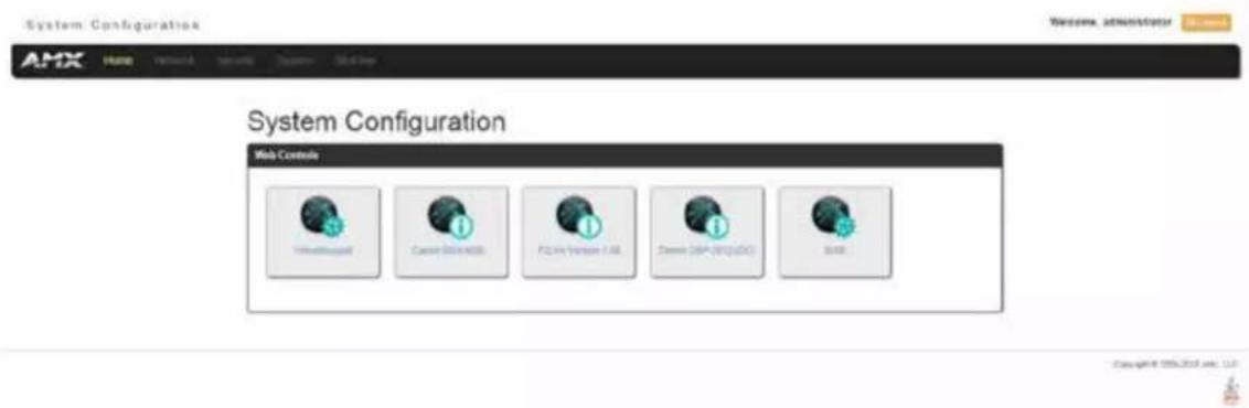
FIG. 62 WebConsole - Web Controls page (initial view)
The options available via the WebConsole differ depending on the on the Presentation System model.
NCITE-813AC WebConsole Options
On the NCITE-813AC, the WebConsole offers six primary sections from a menu located at the top of the page, indicated by six menu options across the top of the main page (FIG. 63):

Home
Network
Security
System
Modules
Switcher
FIG. 63 System Configuration Menu Options (NCITE-813AC)
- Home: This option appears when you access the System Configuration page. Use these options to view any connected device or access a module.
- Network: Click to access the Network Settings for the Master. The options on these pages enable you to view and modify the IPv4 and IPv6 network settings and the clock settings for the system (see the WebConsole - Network Options section on page 56).
- Security: Click to access the System Security page. The options in this page allow you to configure various aspects of NetLinx System and Security on the Master, including network configuration and creating users and roles (see the Web-Console - Security Options section on page 63).
- System: Click to access the System Details page. The options on this page allow you to view and configure various aspects of the NetLinx System (see the WebConsole - System Options section on page 80).
- Modules: Click to access several different device-related pages (see the WebConsole - Modules Options section on page 82).
- Switcher: Click to access the Switcher Configuration page (see the WebConsole - Switcher Options section on page 90). This page only appears for Enova devices.
From the Home page, Web Control options become available (e.g., RMS, Virtual Keypad, and device details pages for any connected devices).
NCITE-813/813A WebConsole Options
On the NCITE-813AC, the WebConsole offers three primary sections from a menu located at the top of the page, indicated by three menu options (Network, Security, and Switcher) across the top of the main page (FIG. 64):

Network
Security
Switcher
FIG. 64 System Configuration Menu Options (NCITE-813/813A)
System Configuration Interface Tips:
- It is recommended that you use the latest, industry accepted version of HTML5 browsers. If a browser is inconsistent, upgrade or try a different browser. To-date, browsers tested include Google Chrome (preferred), Mozilla Firefox, Apple Safari, and Microsoft Internet Explorer 10+/Edge.
- To access the interface after initial setup, simply type the integrated Master's IP address in the address bar of the browser and press the Enter key. You can locate the IP address of your device by using the on-screen menu (see the Using the On-Screen Menu section on page 45 for more information).
- Some devices run on a secured file-system. As such, file-system operations (e.g., Load and Save operations) may not be supported by the device's default capabilities and may require downloading a file manager application.
- When selecting Inputs and Outputs for switches – you may select an input followed by multiple outputs, but only one input is selectable if you select an output first.
- Inputs and Outputs can only have one name each, regardless of whether the name is set via the Video tab or the Audio tab in the Configuration page (or via NetLinx SEND_COMMANDs VIDIN_NAME, VIDOUT_NAME, AUDIN_NAME, AUDOUT_NAME). Inputs and Outputs may be named independently.
Accessing the WebConsole
From any PC that has access to the LAN that the target Master resides on:
-
Open a web browser and type the IP Address of the target Master in the Address Bar.
-
Press Enter to access WebConsole for that Master. The initial view is the Web Control page (FIG. 62).
When using the Microsoft Internet Explorer browser in Windows 8, you may not be able to login and connect to the Master via the WebConsole. If you cannot login and connect, try any of the following options:
- Shift+Right-click Internet Explorer icon and select Run as administrator.
- Select Internet Options | Advanced | Security Settings, and check Enable Enhanced Protection Mode. A Windows 8 restart will be required.
- Use the Master's Hostname instead of its IP numeric address to enter the URL (e.g.: http://AMXM98A1A2B rather than http://192.168.1.123)
- Use a non-Windows 8 device if Internet Explorer 10+ is required.
Default User Names and Passwords
The following table lists the default user names and passwords for accessing the NX-series controllers through NetLinx Studio or the WebConsole.
| Default User Names and Passwords | ||
| User Name Password | ||
| NetLinx Studio netlinx password | ||
| WebConsole administrator password | ||
WebConsole - Network Options
Network Overview
The Network page (FIG. 65) is accessed by clicking Network on the page's main heading. This page allows you to view and configure various aspects of the Master's network:
- IPv4 Setup - Options on this page allow you to view/change the Master's IP and DNS address information. See the Network - IPv4 Setup section on page 57 for details.
- IPv6 Setup - Options on this page allow you to view the Master's IPv6 address information.
- Date/Time - Options on this page allow you to enable/disable using a network time source and provide access to Daylight Saving configuration and which NIST servers to use as a reference. This page is only available on the NCITE-813AC Presentation System. See the Network - Date/Time section on page 59 for details.
- NetLinx Setup - Options on this page allow you to establish NetLinx settings for your system. This page is only available on the NCITE-813/813A Presentation Systems. See the Network - NetLinx Setup section on page 62 for details.
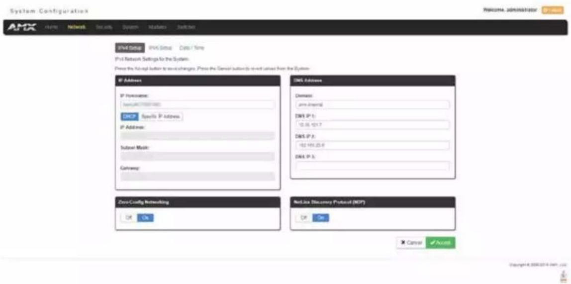
FIG. 65 Network page
Network - IPv4 Setup
Click IPv4 Setup to access the IPv4 Setup page (FIG. 66) and view and configure IP and DNS addresses for the Master. Use the options on this page to view/edit the Master's network settings. A user can only modify the information on this page if it is assigned a Role that includes the Network Configuration permission. Without the proper permission, a user can only view the information on this page.

FIG. 66 Network - IPv4 Setup page
IPv4 Setup Options
The IPv4 Setup options are described in the following table:
| IPv4 Setup Options | |
| Option Description | |
| IP Address: This section enables you to set IPv4 information for the Master's network. | |
| IP Hostname | Enter the IP host name in this field.NOTE: Host names may contain only the ASCII letters 'a' through 'z' (case-insensitive), the digits '0' through '9', and the hyphen ('-'). |
| DHCP/Specific IP Address | Use the buttons to select a DHCP or static IPv4 address. Additional options in this area become available if you selectSpecific IP Address. |
| IP Address | Enter the IPv4 address in this field. This field is only available if you select Specific IP Address. |
| Subnet Mask | Enter the IPv4 subnet mask in this field. This field is only available if you select Specific IP Address. |
| Gateway | Enter the gateway IPv4 address in this field. This field is only available if you select Specific IP Address. |
| DNS Address: This section enables you to set hostname, domain, and DNS information for the Master's network. | |
| Domain | Enter the domain name of the DNS server in this field. |
| DNS IP | Enter up to three DNS server addresses in the provided fields. |
| Zero-Config Networking | Use the buttons to activate zero-config networking functionality on the Master's network. Zero-config networking provides the ability to automatically discover devices that are present on the LAN. By default, zeroconf is enabled (On option selected). With zeroconf enabled, the Master's web interface will be registered via zeroconf and can be viewed through a zeroconf browser plug-in such as Bonjour for IE. |
| NetLinx Discovery Protocol (NDP) | Use the buttons to indicate whether you want the Master to search for any NDP-capable devices currently connected to the Master. |
Network - IPv6 Setup
Click the IPv6 Setup link (on the Network page) to access the IPv6 Setup page (FIG. 67). The options on this page allow you to view the Master's IPv6 network settings. A user can only modify the information on this page if it is assigned a Role that includes the Network Configuration permission. Without the proper permission, a user can only view the information on this page.

FIG. 67 Network - IPv6 Setup page
IPv6 Setup Options
The IPv6 Setup options are described in the following table:
| IPv6 Setup Options | |
| Option Description | |
| IPv6 Address The IPv6 address of the Master. This information is view-only. | |
| IPv6 Subnet Mask The IPv6 subnet mask of the Master. This information is view-only. | |
| IPv6 Gateway The IPv6 gateway of the Master. This information is view-only. | |
Network - Date/Time
Click the Date/Time link (on the Network page) to access the Date/Time page (FIG. 68). The options on this page allow you to enable/disable using a network time source and provide access to Daylight Saving configuration and which NIST servers to use as a reference. This page is only available on the NCITE-813AC Presentation System.
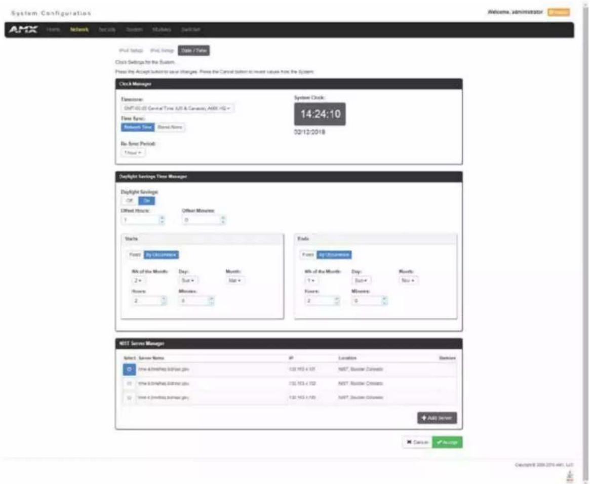
FIG. 68 Network - Date/Time page
The Clock Manager Options are separated into three areas:
1 Clock Manager - The Clock Manager allows you to set the Clock Manager Mode (Network Time or Stand Alone).
Daylight Savings Time Manager - The Daylight Savings Time Manager allows you to specify how and when to implement Daylight Savings rules on the clock.
NIST Server Manager - The NIST Server Manager allows you to connect to a specific NIST (Internet Time Service) Server.
Setting the Mode for the Clock Manager
- In the Manage System tab (FIG. 68), select a Time Sync option.
Network Time: This option allows the Master to manage it's clock by connecting to a NIST (Internet Time Service) Server. When this option is selected, the Master will connect to the default NIST Server to get date and time information.
You can select a different NIST Server (or specify the IP Address of a known NIST Server) in the NIST Server Manager section (see the Selecting a Custom NIST Server section on page 60).
Stand Alone: This option lets the Master use its own internal clock. When this option is selected, two additional fields are available on this tab:
Date - Enter the current date in this field (mm/dd/yyyy).
Time - Enter the current time in these fields (Hours/Minutes/Seconds).
- Click Accept to save these settings to the Master.
Setting Daylight Savings Rules
- In the Daylight Savings Time Manager section (FIG. 69), enable Daylight Savings mode by clicking the On button. Clicking On reveals additional Daylight Savings options.

FIG. 69 Date/Time Options - Daylight Savings Time Manager
- Use the Offset drop-down menus to adjust the amount of time (hours and minutes) to offset Daylight Savings. By default, the offset is set to 1 hour.
NOTE: Although most places that support Daylight Savings usually adjust the local time by one hour this doesn't cover all locations.
To provide flexibility for such locations it is possible to configure a different daylight savings time offset.
- Use the Starts fields to specify when Daylight Savings should start. The Starts rules include:
- Select Fixed to specify the calendar date when the rule applies as a specific date ("March 21"). When Fixed is selected, use the Day, Month, Hours, and Minutes fields to specify the date and time (hh:mm) to start Daylight Savings time.
- Select by Occurrence to specify the calendar date when the rule applies as a heuristic, ("the 3rd Sunday in March"). When by Occurrence is selected, use the Wk of the Month, Day, Month, Hours, and Minutes fields to specify the occurrence to start Daylight Savings time.
The range for Wk of the Month is 1 through Last, where Last indicates the last occurrence of a particular day of the month. This is to accommodate months that include four weeks as well as those that include five.
-
Use the Ends fields to specify when Daylight Savings should end. The Ends rules match the Start rules, and follow the same logic. Select Fixed or by Occurrence, and specify the End date/time information accordingly.
-
Click Accept to save these settings to the Master.
Selecting a Custom NIST Server

FIG. 70 Date/Time Options - NIST Server Manager
- In the NIST Server Manager section (FIG. 70), use the option buttons to select one of the NIST Servers in the list.
- Click Accept to save the selection to the Master.
Adding a Custom NIST Server to the List
- Click Add Server. The Add New Server dialog opens (FIG. 71).

FIG. 71 Add New Server dialog
- In the New Server URL field, enter the URL of the NIST Server. The URL is used only to help you manage entries, and is not verified or used internally by the clock manager.
- Enter the NIST Server's IP Address in the New IP field. This is used internally and must be a valid IP address.
NOTE: The strings entered into the URL and Location fields are not used to connect to NIST Servers. The IP Address (entered into the IP field) specifies the NIST Server(s) that will be used. As stated above, the address entered into the IP field must be must be a valid IP address (not a URL).
- Enter the NIST Server's location in the New Location field. This is used only to help the user manage entries and it is not verified or used internally by the clock manager.
-
Click Accept to save these settings to the Master. Removing an NIST Server From the List
-
Click on the Remove (x) button to the right of a user-added NIST Server in the NIST Server Manager list.
-
Click on the Remove (x) button to the right of a user-added NIST Server in the NIST Server Manager list.
-
Click Accept to save these settings to the Master.
NOTE: The built-in entries cannot be removed. Clock Manager NetLinx Programming API
Refer to Appendix C: Clock Manager NetLinx Programming API in the NetLinx Programming Guide (available at www.amx.com) for a listing and description of the Types/Constants and Library Calls that are included in the NetLinx.AXI to support Clock Manager functions.
Network - NetLinx Setup
Click the NetLinx Setup link (on the Network page) to access the NetLinx Setup page (FIG. 72). The options on this page establish NetLinx settings for your system. This page is only available on the NCITE-813/813A Presentation Systems..

FIG. 72 Network - NetLinx Setup page
ICSP Setup Options
The ICSP Setup options are described in the following table:
| ICSP Setup Options | |
| Option Description | |
| Master Mode This option allows you to set the Master Mode for your system. You can choose from URL, Listen, NDP, Auto, and UDP. | |
| IP/URL The IP address or URL for your system. | |
| Device Number The device number for your system. | |
| System Number The system number that your device belongs to. | |
| Username The username to access the NetLinx system. | |
| Password The password to access the NetLinx system. | |
WebConsole - Security Options
Security Overview
The Security page is accessed by clicking Security on the page's main heading. This page allows you to view configure and modify the Master's security settings at three levels (System, Role, and User). See the Security Presets section on page 68 for more information on the three presets.
- System Level - changes made at this level affect the system globally. See the Security - General section on page 65 for details.
- Role Level - changes made at this level affect specific Roles. See the Security - Roles section on page 69 for details.
- User Level - changes made at this level affect individual Users. See the Security - Users section on page 73 for details.
The default view for the option is System Security Settings (FIG. 73).

FIG. 73 System Security Settings
NOTE: By default, all System-level security options are disabled, except for Authentication On Server Ports, which requires a login for access to the web or command line interface.
Additional security configuration options are available via Terminal/Telnet Commands. See Accessing the Security Configuration Options sections in the NetLinx Programming Guide (available at www.amx.com) for more information.
NOTE: While the Security page exists on NCITE-813/813A Presentation Systems, the options listed in this chapter are not available for these devices.
Login Rules
There is no limit to the number of concurrent logins allowed for a single user. This allows for the creation of a single user that is provided to multiple ICSP devices (touch panels, for example) using the same login to obtain access to the Master. For example, if you have 50 devices connected to a Master, you do not have to create 50 individual user accounts, with one for each device. Instead, you only need to create one which all 50 devices use for access.
The first layer of security for the Master is to prompt a user to enter a valid user name and password before gaining access to a secured feature on the target Master.
Depending on the Security configuration, users may be prompted to enter a valid user name and password before gaining access to various features of the WebConsole. User access is specified by the administrator in the Role and User Level pages of the Security section.
NOTE: This user name and password information is also used by both G5 touch panels (within the System Connection firmware page) and AMX software applications such as NetLinx Studio v 4.0 and above to communicate securely with a Master using encrypted communication.
User and Role Name Rules
User account and role names must follow these rules:
- Case-sensitive
- Must be between 4 and 20 alpha-numeric characters: A-Z, a-z, 0-9
- The following characters are allowed: - _. and
.
Password Rules
The rules for changing a password vary according to the Password Complexity setting for the user. A user's password complexity can be set to Low, Medium, or High.
- Low - Minimum length is 4 characters, and must be different from the previous password.
- Medium - Minimum length is 8 characters, must contain characters from 3 character classes listed in the table below, must contain at least 4 changes from the previous password, and must be different from the previous 10 passwords.
- High - Minimum length is 15 characters, must contain characters from all of the characters classes listed in the table below, must contain at least 8 changes from the previous password, and must be different from the previous 30 passwords.
The requirements for each setting are listed in the following table:
| Password Complexity Requirements | |||
| Requirement Low Medium High | |||
| Case Change Only No No Yes | |||
| Character Classes Required 0 3 4 | |||
| Library Check No No Yes | |||
| Minimum Length 4 8 15 | |||
| Palindrome Check No No Yes | |||
| Same Consecutive Characters No check | 5 3 | ||
| Similarity Check | 1 4 8 | ||
| User Name Check (straight or reversed) | No | Yes | Yes |
| Different from Previous # of Passwords | 1 10 30 |
The definitions of each requirement are listed below:
- Case Change Only: A new password cannot differ from the previous passwords solely by a change in case (upper/lower)
- Character Classes Required: A password must contain characters from a set number of character classes. See the Character Classes table below for the list and definitions of character classes.
- Library Check: The password cannot contain a word from a dictionary file supplied with the OS.
- Minimum Length: The password must contain a minimum set number of characters.
- Palindrome Check: The password does not contain a palindrome of a 7-letter length or greater.
- Same Consecutive Characters: The password does not contain more than a set number of the same consecutive characters.
- Similarity Check: The password differs from the previous password by a set number of characters.
- User Name Check: The password does not contain the user's user name.
- Different from Previous # of Passwords: The password differs from a set number of previous passwords.
The following table lists the characters available in each character class:
| Character Classes | |
| Character Class | Example |
| Uppercase Letters | A-Z |
| Lowercase Letters | a-z |
| Numbers | 0-9 |
| Other Characters | `~!@#$ % ^ & * () _ - + = { } [ ] \ | :; “‘<>, . ?/ (including “space”) |
Security - General
The General Security Settings page provides global permissions for various options that may be individually selected and applied to all users. The Master provides 3 levels of security settings presets: Low, Medium, and High. The levels are simply presets of various security settings. When a preset is selected, the settings are not applied until you click Accept. You can customize any settings as needed on the security preset before accepting and applying the settings. The default for the settings will match the Low presets.
System Level Security - System Security Settings
Click the System Security Settings link to access the System Security Details page (FIG. 74). The options in this page allow you to establish whether the Master will require a valid user name and password be entered prior to gaining access to the configuration options.

FIG. 74 System Security Settings
These are global options that enable or disable the login requirement for both users and roles.
System Security Options
The System Security options are described in the following table:
| System Security Options | |
| Option Description | |
| Security Presets | The Master provides three levels of security setting presets: Low, Medium, and High. Each level is a preset of various security settings (see the Security Presets section on page 68 for more information.) When a preset is selected, that setting is applied after clicking Accept.NOTE: If a security preset is not selected, all subordinate options are grayed-out and not selectable, meaning that the Master is completely unsecured and can be altered by any user (regardless of their rights). |
| Audit Log Select to enable/disable remote syslog. See the Audit Logs section on page 68 for more information. | |
| Banner Display | Select to turn on or turn off banner messages. Banners enable you to display pre- and post-login text in the WebConsole.See the Banners section on page 69 for more information. |
| USB Host Port Select to enable all Type-A USB connectors on the Master. | |
| System Security Options (Cont.) | |
| Option Description | |
| Inactivity Timeout | Select to enable the Master to log out a user after a defined period of inactivity. After enabling the inactivity timeout option, use the spin box to set the number of minutes before the timeout activates. You can set a timeout in the range of 1 to 60 minutes. The default setting is 10 minutes. The timeout applies to Program Port, Telnet, SSH, HTTP, and HTTPS sessions. When the inactivity timeout is enabled, the Master limits the number of concurrent sessions for all non-device accounts to 10. When the number of active sessions is full, any additional login attempts will fall. |
| Password Expiration | Select to force a user to change its password after a set period of time. After enabling the password expiration options, use the spin box to set the interval for password expiration. You can set an amount of time in the range of 1 to 180 days. The default setting is 60 days.NOTE: This option is only valid on locally-maintained accounts. When external LDAP is enabled, only the administrator and device user accounts are affected. |
| Cryptography Strength: | Set the cryptography strength of the Master to Low or High. On the High setting, only FIPS 140-2 validated binarles are used. |
| Password Complexity | Set the password complexity to Low, Medium, or High. When the password complexity level is raised from a lower level to a higher level, the Master requires confirmation from the user. When the user confirms the change, all passwords are marked as expired on all local user accounts, and the passwords must be changed to meet the new complexity requirements. Password complexity requirements are as follows:Low - Minimum length is 4 characters, and must be different from previous password.Medium - Minimum length is 8 characters, must contain characters from 3 of the following characters sets (uppercase letters, lowercase letters, numbers, other characters), must contain at least 4 changes from the previous password, and must be different from the previous 10 passwords.High - Minimum length is 15 characters, must contain characters from all of the following characters sets (uppercase letters, lowercase letters, numbers, other characters), must contain at least 8 changes from the previous password, and must be different from the previous 30 passwords.NOTE: This option is only valid on locally-maintained accounts. When external LDAP is enabled, only the administrator and device user accounts are affected. |
| Lockout Access | Select to enable a lock on a user account after a set number of failed logins. When enabled, use the Attempts spin box to set the number of login attempts allowed. Use the Lockout Duration options menu to indicate the amount of time you want the lockout to last. The default setting is 60 minutes.NOTE: This option is only valid on locally-maintained accounts. When external LDAP is enabled, only the administrator user is affected. |
| HTTP/HTTPS Select to enable HTTP and HTTPS access to the Master.HTTP: The port value used for unsecure HTTP Internet communication between the web browser's UI and the target Master. By disabling this port, the administrator (or other authorized user) can require that any consecutive sessions between the UI and the target Master are done over a more secure HTTPS connection.By default, the Master does not have security enabled and must be communicated with using http:// in the Address field. The default port value is 80.NOTE: One method of adding security to HTTP communication is to change the Port value. If the port value is changed, any consecutive session to the target Master has to add the port value at the end of the address (within the Address field). An example is if the port were changed to 99, the new address information would be: http://192.192.192.192:99.HTTPS: The port value used by web browser to securely communicate between the web server UI and the target Master. This port is also used to simultaneously encrypt this data using the SSL certificate information on the Master as a key. This port is used to communicate securely between the browser (using the web server UI) and the Master using HTTPS but also provide a port for use by the SSL encryption key (embedded into the certificate). Whereas SSL creates a secure connection between a client and a server, over which any amount of data can be sent securely, HTTPS is designed to transmit individual messages securely. Therefore both HTTPS and SSL can be seen as complementary and are configured to communicate over the same port on the Master. These two methods of security and encryption are occurring simultaneously over this port as data is being transferred. The default port value is 443.NOTE: Another method of adding security to HTTPS communication would be to change the port value. If the port value is changed, any consecutive session to the target Master has to add the port value at the end of the address (within the Address field). An example is if the port were changed to 99, the new address information would be: http://192.192.192.192:99. | |
| Telnet/SSH/SSH FTP Access | Select to enable Telnet, SSH, and SSH FTP access to the Master.Telnet: The port value used for Telnet communication to the target Master. Enabling this feature allows future communication with the Master via a separate Telnet application.The default port value for Telnet is 23.Refer to the NetLinx Security with a Terminal Connection section for more information on the related procedures.SSH: The port value used for secure Telnet communication. A separate secure SSH Client would handle communication over this port. When using a secure SSH login, the entire login session (including the transmission of passwords) is encrypted; therefore it is secure method of preventing an external user from collecting passwords.SSH version 2 is supported.The default port value is 22.NOTE: If this port?s value is changed, make sure to use it within the Address field of the SSH Client application. |
| FTP Access Select to enable FTP access to the Master. The default port value used for FTP communication is 21.NOTE: This port can be disabled/enabled, but its value cannot be changed. | |
| Online Certificate Status Protocol (OCSP) | Select to enable usage of the OCSP to validate received certificates before trusting the sending site. |
| Authenticate on Server Ports | Select to require user name and password authentication on Telnet, Program, and HTTP/HTTPS ports. Authentication is always required on FTP/SFTP and SSH ports.NOTE: If Authenticate on Server Ports is disabled but LDAP is enabled, a login is still required. If you do not desire a login, LDAP must also be disabled. |
| Restricted Switcher Mode - DXLink Network/Logo FTP | Select to enable or disable the Switcher Secure Mode on DVX and DGX platforms. During Switcher Secure Mode, the switcher (5002 device) does not allow packet routing between the LAN connector and any DXLink endpoints.Additionally, the switcher disables any open IP ports on the LAN (e.g. Telnet or FTP servers.) |
| Authenticate AMX Devices On ICSLAN Ports | Select to require user name and password authentication on devices connected to the ICSLAN ports on the Master. |
| ICSLAN AMX Device Connection | Select to allow ICSP access to the Master for Device-type users connected to the ICSLAN ports. Expand the ICSLAN AMX Device Connection section to view this option. |
| AMX Device Connection | Select to enable connection to AMX devices from the Master. Expand the ICSLAN AMX Device Connection section to view this option. |
| Secure AMX Device Connection | Select to enable secure connection to AMX devices from the Master. Expand the ICSLAN AMX Device Connection section to view this option. |
| Legacy ICSP Encryption | Select to enable encryption on the legacy ICSP ports on the Master. Expand the ICSLAN AMX Device Connection section to view this option. |
| Authenticate AMX Devices On LAN Ports | Select to require user name and password authentication on devices connected to the LAN ports on the Master. |
| LAN AMX Device Connection | Select to allow ICSP access to the Master for Device-type users connected to the LAN ports. Expand the LAN AMX Device Connection section to view this option. |
| AMX Device Connection | Select to enable connection to AMX devices from the Master. Expand the LAN AMX Device Connection section to view this option. |
| Secure AMX Device Connection | Select to enable secure connection to AMX devices from the Master. Expand the LAN AMX Device Connection section to view this option. |
| Legacy ICSP Encryption | Select to enable encryption on the legacy ICSP ports on the Master. Expand the LAN AMX Device Connection section to view this option. |
Security Presets
The Master provides three levels of security setting presets: Low, Medium, and High. Each level is a preset of various security settings. The following table describes each of the Security Presets presented on the General section of the Security page:
Security Presets
| Preset Low Medium High | |||
| Audit Log Off On On | |||
| Banner Display Off On On | |||
| USB Host Port Enabled Enabled Disabled | |||
| Authentication On Server Ports Required Required | Required | ||
| Inactivity Timeout | Off On On | ||
| Password Expiration | Disabled | Enabled | Enabled |
| Cryptography Strength | Low | Low | High |
| Password Complexity | Low | Medium High | |
| Lockout Access | Off | On | On |
| FTP/SFTP Both enabled Disabled/Enabled Disabled/Disabled | |||
| HTTP/HTTPS | Both enabled | Disabled/Enabled | Disabled/Disabled |
| Telnet/SSH | Both enabled | Disabled/Enabled | Disabled/Disabled |
| OCSP | Disabled Disabled | Enabled | |
| Switcher Secure Mode | Disabled Disabled | Enabled | |
| Authenticate AMX Devices on ICSLAN Ports | Not required | Required | Required |
| ICSLAN AMX Device Connection | ICSPS enabled, ICSP enabled - without encryption | ICSPS enabled, ICSP enabled - with encryption | ICSPS enabled, ICSP disabled |
| Authenticate AMX Devices on LAN Ports | Not required | Required | Required |
| LAN AMX Device Connection | ICSPS enabled, ICSP enabled - without encryption | ICSPS enabled, ICSP enabled - with encryption | ICSPS enabled, ICSP disabled |
Once any of the settings have been modified, press the Accept button to save these changes to the Master. Once these changes are saved, the following message appears: "Device must be rebooted for the setting to take effect. To reboot, go to the System Devices page." A link appears which you can click to jump to the System Devices page (see the System - Devices section on page 81 for more information.) Click the Reboot button to remotely reboot the target Master.
Audit Logs
An audit log includes the date/time of the event, the event type, the software or hardware component where the event occurred, the source of the event, the subject identity, and the outcome of the event. For events related to a remote device, the audit log includes the source and destination network addresses and ports or protocol identifiers. The Master generates an audit record for the following events:
• Each successful or unsuccessful attempt to access security files
- Alerts and errors
- Starting/Shutting down audit logging
- Any blocking (including the reason) of access based on a UID, terminal, or access port
- Any configuration change. The record includes the source and destination network addresses and ports or protocol identifiers.
- Denial of access due to excessive login attempts
• Each log off
• Each successful or unsuccessful attempt to log on to the application
- Successfully or unsuccessfully loading and starting a Duet module
- Modification of permissions associated with roles
- Connection and loss of connection to an NTP server. (Loss of connection is defined as three successive failed polls. A single successful poll constitutes a re-connection.
- System reboot
- Software or firmware updates
- Creation, modification, and deletion of user accounts
NOTE: The Master retains audit log records for 30 days (or less depending on available space), after which they are automatically purged.
Banners
Banners enable you to display pre- and post-login text in the WebConsole and terminal interfaces. Banner files are text files containing up to 5000 characters in each file. (Any additional characters are discarded.)
NOTE: Banner files are user-provided and optional. If no files are found, no banner appears.
The following special characters are allowed for use in banner text messages:
$$ !" # \% \& ^ {\prime} () * +, -. /:; < = >? @ [ \backslash ] ^ {\wedge} _ {-} ^ {\prime} {| } \sim $$
Also allowed are any printable ASCII characters (including "space"): A-Z, a-z, 0-9.
Pre-login banners must be named "banner.txt" and stored in the /user directory on the Master. Post-login banners are obtained from one or more files in the /user directory. Post-login banner text is a concatenation of the allroles_banner.txt file, followed by all of the applicable
NOTE: If you load a new "banner.txt" file with new content to the Master, you must reboot the Master to display the new file.
Security - Roles
A Role is a set of privileges or permissions assigned to one or more users. The privileges and permissions can involve various functions or allow access to specific ports. Any privileges or permissions set for a role are inherited by all users sharing that role. Multiple roles can be assigned to a user, but at the same time, roles are not required for users. A user can have zero roles assigned to it.
NOTE: You cannot assign a permission directly to a user. All user permissions are determined by the Role assigned to the user.
NOTE: If you have a remote directory such as LDAP enabled, the common name of the LDAP group on the LDAP server must match the name of the Role assigned to the user on the Master.
Select the Roles option of the Security Page to access the Role Security Details page (FIG. 75).

FIG. 75 Security - Roles page
The options in this page allow authorized users to assign and alter role properties such as creating, modifying, or deleting a role's rights, locking a role, and defining the files/directories accessible by a particular role. Locking a role disables the role without deleting it.
Default Roles
By default, the NetLinx Master creates the following accounts, access rights, directory associations, and security options:
| Default User Accounts | |
| All_Permissions Studio | |
| Permissions: All Permissions: | Device ManagementFirmware/Software UpdateNetwork ManagementSecurity ControlGeneral Configuration |
Role Permissions
The following table lists the permissions available for Roles:
| Role Permissions | |
| Option Description | |
| Audit Log Select to | allow the role to view and configure the audit log. |
| Device Configuration | Select to allow the role to modify the configuration of NetLinx and 3rd party devices including the following:• System number• Device number• Integrated device settings• Switcher device settings (DVX or DGX)•RebootNOTE: This permission is not required to view the information, only to change it. |
| Firmware/Software Update | Select to allow the role to update firmware and software. This setting allows Device access via ICSP with user credentials.NOTE: This permission also includes the right to reboot the Master after the update. It does not include the right to reboot the Master outside of this context or to reboot any other devices. |
| FTP Access Select | to allow the role to have FTP access. |
| General Configuration | Select to allow the role to modify general configuration including access to WebControl for RMS and RPM configuration, importing and exporting configuration files, and the following parameters:• Auto-locate enable/disable• Device Holdoff setting• Duet memory allocation• ICSP TCP timeout• Master-to-master route mode• Message log length• Message thresholds for threads• Queue sizes for threads• UDP broadcast rateNOTE: This permission also includes the right to reboot the Master after the configuration change. It does not include the right to reboot the Master outside of this context or to reboot any other devices.NOTE: This permission is not required to view the information, only to change it. |
| HTTP/HTTPS Select | to allow the role to have HTTP and HTTPS access through the web interface. |
| Network Configuration | Select to allow the role to modify network configuration including the following:• Clock Manager settings• DHCP/Static setting (Gateway IPv4 address, IPv4 address, IPv4 subnet mask (if static selected))• DNS server addresses• Domain name• Hostname• zeroconfig enable/disableNOTE: This permission also includes the right to reboot the Master after the configuration change. It does not include the right to reboot the Master outside of this context or to reboot any other devices.NOTE: This permission is not required to view the information, only to change it. |
| Program Port Access | Select to allow the role to have terminal access via the Program Port. |
| Security Control | Select to allow the role to view and configure security including the following:• Audit log enable• Authentication on server ports enable• Authentication on ICSP LAN ports enable• Authentication on ICSP ICSLAN ports enable• Banner display enable• CAC authentication enable• Cryptographic options• Lockout on failed logins enable• FTP/SFTP enableNOTE: This permission also includes the right to reboot the Master after the configuration change. It does not include the right to reboot the Master outside of this context or to reboot any other devices.NOTE: This permission is not required to view the information, only to change it. |
| Telnet/SSH/SSH FTP Access | Select to allow the role to have Telnet, SSH, and SSH FTP access. |
| Option Description | |
| Touch Panel Administration | Select to allow the Master to access a touch panel's settings page. |
| User Access 1-4 | Select to allow the role access generic access permissions. These privileges are to be used by NetLinx programs. |
| User Management Select | Select to allow the role to view, create, modify, lock, and remove user accounts.NOTE: A user has the ability to change its own password, regardless of whether it has the User Management permission. |
Adding a New Role
- Select the Roles option (in the Security section) to open the Role Security Details page.
- Click the Add Role button (see FIG. 76) to access the Add New Role page (FIG. 76).
Add New Role
Role Name:

Please enter between 4 to 64 characters. Name entry elows alphanumeric, and these symbols - _ # only.
Permissions:


× Cancel
√ Accept
FIG. 76 Add New Role
-
In the Role Name field, enter a unique name for the new role.
-
The name must be a valid character string consisting of 4 - 20 alpha-numeric characters. See the User and Role Name Rules section on page 64 for a complete list of valid characters.
- The string is case sensitive and must be unique.
- The terms "All_Permissions" and "Studio" cannot be used for a new role name since the names already exist by default.
NOTE: If you have a remote directory such as LDAP enabled, the common name of the LDAP group on the LDAP server must match the name of the Role assigned to the user on the Master.
- Enable the security access rights you want to provide to the role. By default, all of these options are disabled. See the Role Permissions section on page 70 for details.
- Click the Accept button to save your changes to the target Master.
If there are no errors within any of the page parameters, a "Role added successfully" message displays at the top of the page.
NOTE: Security changes made from within the web browser are applied instantly without the need to reboot.
Viewing and Modifying Role Security Settings Details
Click any Role listed on the Role Security Details page to expand the view to show details for the selected user Role (FIG. 77):

FIG. 77 Role Security Details Page
- Select the Roles option (in the Security section) to open the Role Security Details page.
- Click any Role listed on the Role Security Details page to expand the view to show details for the selected user Role.
- Modify the previously configured access rights by enabling/disabling the check boxes. See the Role Permissions section on page 70 for details.
- Click Accept to save your changes to the Master.
If there are no errors with the modification of any of this page's parameters, a "Role updated successfully" is displayed at the top of the page. NOTE: The "All_Permissions" user name cannot be modified or deleted.
Any properties possessed by roles (ex: access rights, update rights, directory associations, etc.) are inherited by users assigned to that particular role.
Unchecking a security option (which is available within the associated role) does not remove that right from the user. The only way to remove a role's available security right from a target user is either to not associate a role to a user or to alter the security rights of the role being associated.
Deleting a Role
- Select the Roles option (in the Security section) to open the Role Security Details page.
- Click the Edit button (see FIG. 77) for any Role listed on the Role Security Details page to expand the view to show details for the selected Role.
- Click Delete to remove the selected role and refresh the page. The system will prompt you to verify this action - click OK to proceed.
If the role is associated with several users, you might get an error while trying to delete the role. If this happens, change the role association of
those specific users utilizing the old role and either give them a new role or assign them (none) as a role. When you return to delete the desired role, you receive a message saying "Role deleted successfully". - Click the Accept button to save your changes to the Master.
Locking/Disabling a Role
- Select the Roles option (in the Security section) to open the Role Security Details page.
- Click the Lock button (see FIG. 77) for any Role listed on the Role Security Details page to lock and disable the Role. Click the Lock button again to unlock and enable the Role
NOTE: Any Role can be disabled except for the All_Permissions role.
Security - Users
Select the Users option on the Security Page to access the User Security Details page (FIG. 78). The options on this page allow authorized users to add/delete/lock User accounts and configure User's access rights. Locking a user account disables the account without deleting it.

FIG. 78 Security - Users page
A User represents a single client of the Master, while a Role specifies a set of privileges and permissions which can be assigned to a user. An administrator can assign up to 5 roles to a single user. Any properties possessed by a role are inherited by all of the users assigned to the role.
Default User Accounts
By default, the NetLinx Master creates the following accounts, access rights, directory associations, and security options:
| Default User Accounts | |
| administrator netlinx | |
| Username: administrator Username: netlinx | |
| Password: password Password: password | |
| Role: All_Permissions Role: Studio | |
| Directory Association: /* Directory Association: none | |
| NOTE: You can delete and/or modify the “administrator” user account to optimize system security. If deleted, you can create a new user with the “administrator” user name with its own proper settings, provided LDAP is not enabled. | NOTE: The “netlinx” user account is compatible with previous NetLinx Master firmware versions. This account is initially created by default and can later be deleted or modified. |
- FTP Security is always enabled on the Masters.
- All other security options are disabled by default.
Adding a New User
TIP: For a quicker configuration, it is recommended to define all roles and permissions before defining users.
- Select the Users option (in the Security section) to view the User Security Details page.
- Click the Add User button (see FIG. 78) to access the Add New User page (FIG. 79).
Add New User
User Name: *

Type:
Device
Please enter between 4 to 20 characters. Name entry allows alphanumerics, and
these symbols ... # only
Roles:
None Selected
Your new password must be between 4 to 20 characters.
New Password: *
Confirm Password: *
Permissions:

FIG. 79 Add New User
-
In the User Name field, enter a unique name for the new role.
-
The name must be a unique alpha-numeric character string (4 - 20 characters), and is case sensitive.
- The words "administrator" and "NetLinx" cannot be used since they already exist by default.
NOTE: The Type field indicates the type of account for the user. This field lists either Normal or Device. Normal users are any users which access the web interface, Telnet, or NetLinx Studio, and must be assigned to a Role with those permissions assigned to it. Device connections are required for machine to machine over ICSP, such as touch panels and ICSLan device control boxes. Device-type users are stored only in the local user database and are able to be modified even when a remote directory service is enabled.
- From the Roles options menu, choose from a list of roles and associate the rights of the role to the new user. You can assign up to 5 roles to a user.
- Enter a user password in both the Password and Password Confirm fields. The password must conform to the rules set by the Password Complexity level set on the User account. See the Password Rules section on page 64 for more information.
- Select Force Password Change if you want the user to change its password on its next login. This option is not available for Device users.
- Click the Accept button to save your changes to the Master.
NOTE: Any security changes made to the Master from within the web browser are instantly reflected within a Terminal session without the need to reboot, unless otherwise notified.
Viewing and Editing User Security Settings
Click any User listed in the User Security Details page to view the security settings for the selected User (FIG. 80):

FIG. 80 Security - Users page
- Click the Edit button for the User you want to edit to expand the User's details.
- Make any necessary changes to the selected User, and click Accept for the changes to take effect.
Deleting a User
- Select the Users options (in the Security section) to open the User Security Details page.
- Click the Edit button for the User you want to delete to expand the User's details.
- Press the Delete button to remove the selected User and refresh the page. The system will prompt you to verify this action - click OK to proceed.
- Reboot the Master via the Reboot button on the Manage System Page (select the System control button to access).
Locking/Disabling a User
- Select the Users option (in the Security section) to open the User Security Details page.
- Click the Lock button (see FIG. 78) for any user listed on the User Security Details page to lock and disable the user. Click the Lock button again to unlock and enable the user.
Security Settings - LDAP
The LDAP page provides configuration and tests connection to a remote directory service via LDAPv3. The master supports the option of an insecure or secure connection. The secure option is supported via "LDAPS", or LDAP over SSL/TLS on port 636. Select the LDAP option on the Security Page to access the LDAP Settings page (FIG. 78). The options on this page allow authorized users to enable and modify LDAP security settings.
FIG. 81 Security - LDAP page
LDAP Options
All parameters are case sensitive and must be entered exactly as they are entered into the LDAP database. You can also perform LDAP Client Configuration via terminal commands to the NetLinx Master's Program Port - see the Enabling LDAP via the Program Port section in the NetLinx Programming Guide (available at www.amx.com) for details.
See Appendix A: LDAP Implementation Details in the NetLinx Programming Guide (available at www.amx.com) for additional information on implementing LDAP on the NetLinx Master. The LDAP options are described in the following table:
| LDAP Options | |
| Option Description | |
| LDAP Enabled: This parameter enables the LDAP configuration parameters described below. NOTE: When LDAP is enabled, you can only create device users. If the administrator user has been deleted, you must perform a factory reset of the Master via pushbutton to restore the administrator user. | |
| LDAP URI This parameter has the syntax ldap[s]://hostname:port. • The ldap:// URL is used to connect to LDAP servers over unsecured connections. • The ldaps:// URL is used to connect to LDAP server over Secure Sockets Layer (SSL) connections. • The hostname parameter is the name or IP address, in dotted format, of the LDAP server (for example, LDAPServer01 or 192.202.185.90). • The port parameter is the port number of the LDAP server (for example, 696). NOTE: The standard unsecured port number is 389 and the standard secured port number is 636. | |
| LDAP BASE DN | This parameter specifies the Distinguished Name (DN) of an entry in the directory. It identifies the entry that is the starting point of the user search. |
| BIND DN | This parameter specifies the Distinguished Name (DN) to use to bind to the LDAP server for the initial search for the user's DN. |
| User Query Attr | This LDAP attribute is used for the AMX equipment user search (for example, UID). NOTE: This attribute MUST be unique in the context of the LDAP BASEDN or the search will fail. |
| Search Password This is the password used for the initial bind to the LDAP server - it is the password associated with BIND DN. | |
Click the LDAP enabled check box to make the LDAP options available for selection.
- When LDAP is enabled, users are authenticated using the configuration set up on the LDAP server.
- The "administrator" user is handled by the local NetLinx Master, and does not connect to the LDAP server for user verification.
- If an administrator password change is desired, LDAP must be disabled, the password changed and saved and then LDAP re-enabled.
- Users may not be added or deleted via the web pages when LDAP is enabled.
- User access privileges cannot be changed via the web pages.
- As users log onto a NetLinx Master, their user name and access privileges are displayed on the User Security Details page (see Security - Users section on page 73). This information is stored in the master's RAM but is not written to non-volatile memory, and is lost after rebooting the Master.
- If a user is removed from the LDAP directory tree, access is denied, and if that user name is on the master's User Security Details web page it is removed.
Accepting Changes
Click the Accept/Test button to save changes on this page. Accepting changes is instantaneous and does not require rebooting the Master.
Testing the Connection to the LDAP Server
After entering and accepting the parameters, the Accept/Test button can be used to test the connection to the LDAP server. This test does a bind to the BIND DN using the Search Password entered. • If the bind is successful, the message Connection successful is displayed.
- If the server could not be reached or the bind is unsuccessful, the message Could not connect to server -- Please check LDAP URI, BIND DN and Search Password settings is displayed.
Refer to Appendix A: LDAP Implementation Details in the NetLinx Programming Guide (available at www.amx.com) for additional information.
IMPORTANT: For the NX-series Masters to work with LDAP over SSL (LDAPS), you must upload a CA server certificate in .pem format to the Master's FTP server. The certificate's file name must be "ldap_ad.pem" and the file must be saved in a folder named "certs". Once the file is uploaded, you must reboot the Master for the certificate file to be read and employed by the system. LDAPS requires Master Firmware version 1.3.78 or greater.
Wired 802.1X support
IEEE 802.1X is an IEEE Standard for Port-based Network Access Control (PNAC). PNAC provides the ability to grant or deny network access to devices wishing to attach to a LAN based on credentials tied to the device rather than to a user. Until the device has been verified and permitted access, no network traffic is passed through the connected port, effectively keeping the device disconnected from the network.
The NX-Series controller acts as a supplicant (client device) to a wired 802.1X enabled network and presents customer-provided X.509 certificates to be allowed access to protected networks. The following EAP Encryption Methods are supported.
- PEAPv0/MSCHAPv2
- TTLS/MSCHAPv2
- TTLS/PAP
MD5
Customer provided X.509 certificates are uploaded to the NX-Series controller using NetLinx Studio, and 802.1x is configured via the Command Line Interface and the syntax:
DOT1X [status|enable|disable]
Once you add the certificate file to your workspace, NetLinx Studio transfers the file to the appropriate directory on the controller.
- Click to select (highlight) a System (in the Workspace tab of the Workspace Bar).
- Right-click on the Other folder to access the Other File Folder context menu, and select Add Existing Other File.
- In the Add Existing Other File dialog, locate and select the certificate file (.crt) that you want to add to the selected System. Change the Files of Type option to All Files (*.*) to look for other file types, if necessary.
- Click Open to access the File Properties dialog, where you can view/edit general file information for the selected file.
- Click OK to add the file to the selected System. The file should now appear in the Other folder under the selected System.
Security - Profile
The Profile page (FIG. 82) enables a user to see its own roles and permissions. The user cannot change the roles and permissions on this page. The Change Password option for user accounts is available on this page.

FIG. 82 Security - Profile page
Changing a User Account Password
Consult the Password Rules section on page 64 for password requirements for each level of security.
- Select the Profiles option (on the Security page) to open the Profiles page.
- Click Change Password. The Change Password window opens (FIG. 83).

FIG. 83 Change Password window
- Enter the current password in the Old Password field.
- Enter the new password in the New Password field, then enter it again in the Confirm Password field.
- Click Accept.
WebConsole - System Options
System Overview
The System page is accessed by clicking System on the page's main heading. This page allows you to view and configure various aspects of the NetLinx System:
- System Information - Options on this page allow you to view a detailed list of the properties of the Master. See the System - Info section on page 80 for details.
- Devices - Options in this tab allow you to view the details of additional attached devices (including module-supported third-party devices). See the System - Devices section on page 81 for details.
NOTE: This page is not available on the WebConsole for NCITE-813/813A devices. You can find the information listed on the Info tab on the Switcher - Status page for these devices. See the Status Page section on page 100 for more information.
The default view for the System option is Manage System / System Number (FIG. 84).

(https://2005-0318/s661.1.2)
FIG. 84 System - Info page
System - Info
The Info page (FIG. 84) enables you to view a detailed list of the properties of the Master. The properties include the Model ID and serial number of the Master, network addresses, and firmware versions. This information is view-only. See the WebConsole - Network Options section on page 56 for information on changing the network address of the Master.
System - Devices
The Devices page (FIG. 85) contains information about the Master and any connected devices. Select a device from the Device List and its information appears in the Device Information area. The information in this area is view-only, unless the device allows a change to its device number. If so, you can change the device number on this page (see Changing the Device Number on a Device below for more information.) Masters also include a system number which a user can change with proper access (see Changing the System Number on the Master below for more information.)

FIG. 85 System - Devices page
Changing the System Number on the Master
- Select the Master from the Device List.
-
Enter the new numeric value into the New System Number field.
-
Click the Accept button to save this new value to the system on the target Master. The message "System number changed to X. Master must be rebooted for the change to take effect." reminds you that the Master must be rebooted before the new settings take effect.
-
Click Reboot to reboot the target Master. The Device Tree then reads "Rebooting...". After a few seconds, the Device Tree refreshes with the current system information (including the updated system number assignment.) If the Device Tree does not refresh within a few minutes, press the Refresh button and reconnect to the Master.
Changing the Device Number on a Device
Note that in most cases, the Device Number for Masters should remain set to zero.
- Select the device from the Device List. Ensure the device has a device number.
- Enter the new numeric value into the Device Number field.
- Click the Accept button to save this new value to the system on the target device.
Resetting the Master Controller to the Factory Defaults Configuration
Click the Reset to Factory Defaults button. Clicking the button resets the Master to its factory default state. Resetting to the factory default state includes the following tasks:
- Removing all security settings
- Removing all user files and recreating the administrator and netlinx user accounts
- Removing all roles and recreating the All_Permissions and Studio roles
- Resetting the IP address to DHCP
- Loading an empty NetLinx program
Once reset, the Master will be effectively in an out-of-box state.
NOTE: It may be necessary to refresh the browser window after the master has finished booting (click Refresh).
WebConsole - Modules Options
Modules Overview
The Modules page is accessed by clicking Modules on the page's main heading. This page allows you to view and configure various aspects of the NetLinx System:
- Device Options - Options on this page display various details specific to additional (non-NetLinx) System Devices. See the Modules - Device Options section on page 83 for details.
- Bindings - Options on this page allow you to view the details of additional attached devices (including module-supported third-party devices). See the Modules - Bindings section on page 84 for details.
- User-Defined Devices - Options on this page provide a listing with all of the dynamic devices that have been discovered in the system, and allow you to add and delete User-Defined Devices. See the Modules - User-Defined Devices section on page 87 for details.
- Active Devices - Options on this page allow you to check devices for compatible Duet Modules. See the Modules - Active Devices section on page 88.
The default view for the Modules option is Device Options (FIG. 86).
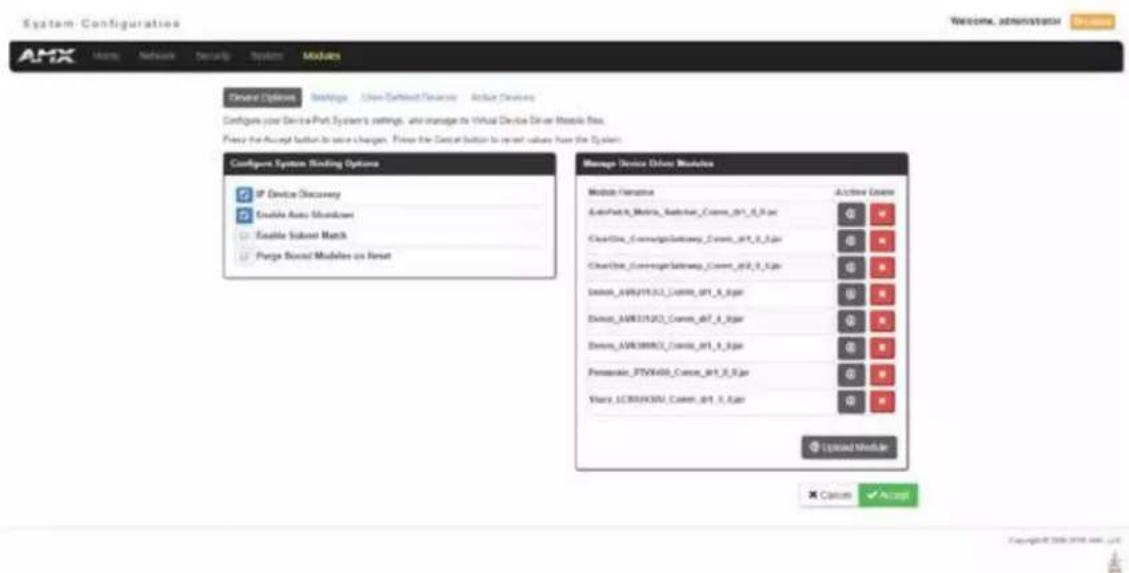
FIG. 86 Modules - Device Options page
NOTE: This page is only available on the NCITE-813AC Presentation System.
Modules - Device Options
Click the Device Options link (in the Manage Devices tab) to access the Details for Additional Devices page (FIG. 86). The options on this page display various details specific to additional (non-NetLinx) System Devices.
Configuring Device Binding Options
- Use the Configure System Binding Options to specify how the Master will manage Bound Devices:
| Configure System Binding Options | |
| Option Description | |
| IP Device Discovery | This option enables you to specify whether you want the Master to scan your network and locate any devices connected to it. |
| Enable Auto Shutdown | Auto-Shutdown forces the termination of modules that have lost communication with their respective physical device. This capability is needed for plug-and-play support.By default, Auto-Shutdown is enabled. If automatic termination of modules when they have lost communication is not desired, this selection should be disabled. |
| Enable Subnet Match | This selection allows you to specify whether or not IP devices should only be detected/discovered if they are on the same IP Subnet as the Master. |
| Purge Bound Modules on Reset | This selection indicates that all modules should be deleted from the bound directory upon the next reboot.During the binding process, the associated Duet modules for a device are copied from the /unbound directory into a protected /bound area.Due to the dynamic nature of Java class loading, it is not safe to delete a running .JAR file. Therefore, this selection provides the administrator the capability of removing existing modules upon reboot by forcing a re-acquisition of the module at blind time.This selection is a one-time occurrence. Upon the next reboot, the selection is cleared. |
- Press the Accept button to save your changes.
Managing Device Driver Modules
Use the Manage Device Driver Modules set of options to upload, archive, or delete modules from the Master. All modules currently present on the Master are indicated in the Module list.
Uploading a Module
Perform the following steps to browse for a Module file and then upload it to the Master:
- Click Upload Module to browse for Duet Modules on your PC/Network.
- Select the JAR file that you want to upload to the Master.
- Click the Open button to upload a copy of the selected JAR file to the target Master's /unbound directory. Only JAR file types are allowed for Upload to the target Master.
Archiving a Module
Click the Archive button next to the module you want to archive. This action copies the selected module (*.JAR) file to your PC. Your PC may require you to confirm this action depending on its security settings.
Deleting a Module
Select a module and click the Delete Module button. This action deletes the selected module from the /unbound directory.
NOTE: Any corresponding module within the /bound directory will not be deleted. Bound modules must be deleted via the Purge Bound Modules on Reset selection described in the Configure System Binding Options section.
Modules - Bindings
Click Bindings to access the Device Bindings page (FIG. 87). Use the options on this page to configure application-defined Duet virtual devices with discovered physical devices.

FIG. 87 Modules - Bindings
The table on this page displays a list of all application-defined devices, including each device's "Friendly Name", the Duet virtual device's D:P:S assignment, the associated Duet Device SDK class (indicating the type of the device), and the physical device's D:P:S assignment. This information has to be pre-coded into the NetLinx file currently on the Master.
Configuring Application-Defined Devices
Elements such as DUET_DEV_TYPE_DISPLAY and DUET_DEV_POLLED are defined within the NetLinx.axi file.
The NetLinx.axi file contains both the new API definitions, as well as the pre-defined constants that are used as some of the API arguments (ex: DUET_DEV_TYPE_DISPLAY).
NOTE: Physical device names are typically prefixed with "dv" and Virtual device names are typically prefixed with "vdv".
Example Code:
PROGRAM_NAME='DDD'
DEFINE_DEVICE
COM1 = 5001:1:0
COM2 = 5001:2:0
dvDisplay = 41001:1:0 dvVideoProjector = 41002:1:0
DEFINE_CONSTANT
DEFINE_TYPE
DEFINE_VARIABLE
DEFINE_START
STATIC_PORT_BINDING(dvDisplay, COM1, DUET_DEV_TYPE_DISPLAY, 'statbcc Display', DUET_DEV_POLLED)
DYNAMIC_POLLED_PORT(COM2)
DYNAMIC_APPLICATION_DEVICE(dvVideoProjector, DUET_DEV_TYPE_VIDEO_PROJECTOR, 'statbcc Serial Projector')
(**)
(* THE EVENTS GO BELOW *)
(**)
*DEFINE_EVENT
DATA_EVENT [dvVideoProjector]
{
    // Duet Virtual device data events go here }
You can find this example code within the DEFINE_START section of your code. This code is reflected in the first two entries listed in FIG. 87. The code gives the Master a "heads-up" notification to look for those devices meeting the criteria outlined within the code.
Application Devices and Association Status
There are two types of application devices: Static Bound application devices and Dynamic application devices:
- Static Bound application devices specify both a Duet virtual device and its associated Device SDK class type, as well as a NetLinx physical device port to which the application device is always associated (i.e. statically bound).
- Dynamic application devices specify both the Duet virtual device and its associated Device SDK with no association to a physical port. Binding of an application device to a physical device/port occurs at run-time (either via auto-binding or manual binding).
Application devices that have a "bound" physical device display their physical device ID within the Physical Device column. If an associated Duet module has been started to communicate with the device, its associated property information is displayed in a mouse-over popup dialog when the cursor hovers over the physical device ID (see FIG. 88). Each entry in the table has one of four buttons to the right of the Physical Device D:P:S assignment:
- Static Bound application devices will either be blank, or display a Release button:
- Static Bound application devices that have not yet detected a physical device attached to their associated port have a blank button.
- Once a physical device is detected and its associated Duet module has been started, a Release button appears. Click Release to force the associated Duet module to be destroyed. The firmware then returns to detecting any physical devices attached to the port.
• Dynamic application devices either display a Bind or Unbind button:
- Dynamic application devices that have been bound display an Unbind button. When you select Unbind, any associated Duet module is destroyed and the "link" between the application device and the physical device is broken.
- Dynamic application devices that have not been bound to a physical device display a Bind button. When this button is selected, a secondary display appears with a listing of all available unbound physical devices that match the application device's Device SDK class type.
NOTE: If a currently bound device needs to be replaced or a Duet Module needs to be swapped out, the device should be unbound and the new module/driver should then be bound.
The administrator/user can select one of the available physical devices to bind with the associated application device. When you click Accept, the binding is created and the target Master attempts to locate the appropriate Duet Module driver. Once the Master locates a driver, the Duet Module started and becomes associated with the specified application device (Duet virtual device). If the you click Cancel button, the binding activity aborts.
NOTE: If the manufacturer device does not support Dynamic Device Discovery (DDD) beaconing, you must use the Add Device page to both create and manage those values necessary to add a dynamic physical device. This process is described in detail in the Modules - User-Defined Devices section on page 87.
Viewing Physical Device Properties
Hold the mouse cursor over the Physical Device entry in the table to display detailed device properties for that device in a pop-up window (FIG. 88). You can only view the device properties for bound devices.

FIG. 88 Device Bindings - Device Properties pop-up
Modules - User-Defined Devices
Click the User-Defined Devices link (in the Manage Devices tab) to access the User-Defined Devices page (FIG. 89). This page provides a listing with all of the dynamic devices that have been discovered in the system, and allows you to add and delete User-Defined Devices.

FIG. 89 Modules - User-Defined Devices Adding a User-Defined Device
- Click the Add Device button (in the User-Defined Devices page) to access the Add User Defined Device page (FIG. 90):
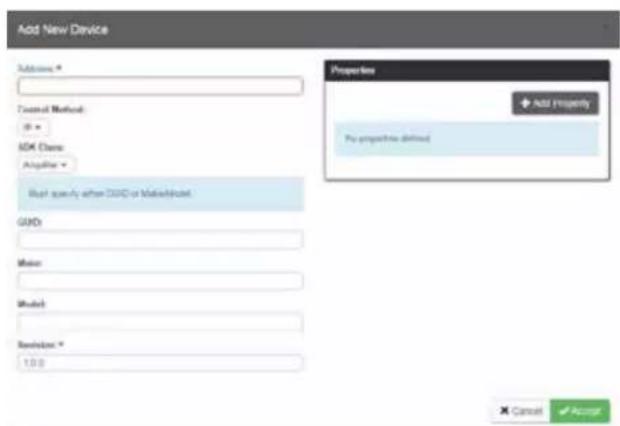
FIG. 90 User-Defined Devices - Add New Device
- Fill in the device information fields, as described in the following tables:
| User-Defined Device Information Fields | |
| Address: | Enter the address of the physical device in the Address field. This information can be either the NetLinx Master port value (D:P:S) or an IP Address (#.#.#.#). |
| Control Method: | Use the drop-down list to select the control method associated with the physical target device (IR, IP, Serial, Other). |
| SDK Class: | Use the drop-down list to select the closest Device SDK class type match for the physical target device. The SDK Class Types table on page 88 provides a listing of the available choices. |
| GUID: | Enter the manufacturer-specified device's GUID (Global Unique Identification) information. You must specify either the GUID or Make/Model. |
| Make: Enter the name of the manufacturer for the device being used (ex: Sony, ONKYO, etc.)• Up to 55 alpha-numeric characters• Spaces in the name will be converted to underscores. | |
| Model: | Enter the model number of the device being used (ex: Mega-Tuner 1000). You can enter up to 255 alpha-numeric characters. |
| Revision | Enter the firmware version used by the target device. Text is required within this field. The version must be in the format: major.minor.micro (where major, minor, and micro are numbers). An example is: 1.0.0 (revision 1.0.0 of the device firmware). |
SDK Class Types
| Amplifier Digital Video Recorder MultiWindow Text Keypad | |||
| AudioConferencer Disc Device PoolSpa TV | |||
| AudioMixer Display PreAmp Surround Sound Processor UPS | |||
| AudioProcessor Document Camera Receiver Utility | |||
| AudioTape | HVAC | RelayDevice | VCR |
| AudioTunerDevice | IODevice | RFID System | Video Conferencer |
| Camera | Keypad | Security System | Video Processor |
| Digital Media Decoder | Light | Sensor Device | Video Projector |
| Digital Media Encoder | Light System | Set Top Box | Video Wall |
| Digital Media Server | Monitor | Slide Projector | Volume Controller |
| Digital Satellite System | Motor | Switcher | Weather |
- When you are finished with creating the profile for the new device, click the Add Property button to access the Name and Value fields property information for association with the new User Defined Device. This information appears in the Physical Device Properties for each device. See the Viewing Physical Device Properties section on page 89 for more information.
- Click the Accept button. The new device is indicated in the list of discovered physical devices (in the User-Defined Devices page).
Modules - Active Devices
Click the Active Devices link (in the Manage Devices tab) to access the Active Devices page (FIG. 91). The options on this page allow you to check devices for compatible Duet Modules.
FIG. 91 Modules - Active Devices

Searching For All Compatible Duet Modules for a Selected Device
- Click the Search button for any device to search for a Duet Module for that particular device. This action initiates a search for compatible modules. Modules that are retrieved from either the Internet or from the manufacturer's device are then placed into the /unbound directory and automatically overwrite any existing module of the same name. If the device specified a URL in its DDD beacon, the file is retrieved from the URL either over the Internet or from the physical device itself, provided the device has an onboard HTTP or FTP server.
- Once a list of all compatible modules is compiled, the list of available Duet Modules appears on this page. Each module is listed with its calculated "match" value. The greater the "match" value, the better the match between the Duet Module's properties and the physical device's properties.
- Select a module and click the Accept button to associate the selected Duet module with the physical device. NOTE: This action will not affect any currently running Duet module associated with the physical device. The module is associated with the device upon reboot.
Viewing Physical Device Properties
Hold the mouse cursor over the Device entry in the table to display detailed device properties for that device, in a pop-up window (FIG. 92).

FIG. 92 Active Devices - Device Properties pop-up
WebConsole - Switcher Options
Switcher Overview
The Switcher page (FIG. 93) is accessed by clicking Switcher on the page's main heading. This page allows you to route the system's inputs to its outputs during system setup:
- Configuration - Options on this page allow you to configure audio and video inputs and outputs. See the Configuration Page section on page 91 for details.
- Status - Options on this page allow you to check a number of the switcher's components and their states. See the Status Page section on page 100 for more details.
- Windows - Options on this page allow you to set options for transitioning between video outputs or setting up Picture in Picture (PIP). See the Windows Page section on page 101 for more details.

FIG. 93 Switcher page
Each input and output can be labeled by filling in the Input Name or Output Name field on the respective Video or Audio tab on the Configuration page.
Configuration Page
The Configuration page is used to configure inputs and outputs in the system. The most recently selected input or output displays in the Configuration page. The Configuration page displays the Switching page components on the left. Note that the components are active, i.e., they can be used for all switching functionality.

FIG. 94 Configuration page allows configuration of inputs and outputs
Configuration Components
The Configuration page features the following components:
Inputs section – This section contains buttons for each of the available input signals in the system. Click the input button that needs to be switched.
Outputs section – This section contains buttons for each of the available output signals in the system. Note that when the currently selected button is an output, it also appears in the Configuration page with signal details (for button/signal details, click the Legend button).
Legend button – Click to open an additional window tab (Audio/Video Legend) which displays the legend key with details regarding the state of the input (source) and output (destination) connections. The browser tab opens in a tearaway tab/window that can be dragged and dropped as a standalone desktop window for side-by-side reference with the Switcher/Configuration pages.
NOTE: The label on the title bar can be edited in the Input or Output Name field on the Configuration page.

Any changes made in the Configuration page occur instantaneously on the attached devices. In addition, when you select an input or an output on the left, the options on the right side of the page change to reflect the current settings. Configuration is not affected by power loss, restarting the enclosure, or upgrading the firmware.
Input and Output buttons are selected individually for configuration.
Video (default) and Audio tabbed views – click tabs to configure the video or audio signal that is selected on the Configuration page. The signal will be either input or output depending on the Config Viewer button selection. The setting options vary depending on the signal.
Selecting any video or audio signal button will display corresponding information as follows:
Input or Oulput button – an enlargement of the button selected under Switching (or from the Switching page) appears on the Configuration side with the source name and number, plus signal details (for an explanation of the button's details, click the Legend button).

Input Name or Output Name field – use to label the buttons in the Switching pane (and on the Switching page).
Type the name in the field and press Enter on the keyboard.
Video Settings
Video settings display when the Switch Mode is A/V or Video, the Video tabbed view is selected, and a specific input or output is selected.
Inputs
- General:

- Resolution – Displays Resolution (read-only).
- EDID Mode – From the drop-down list, select the resolution type (4K, 4K60, All HD Resolutions, HD Wide-Screen, HD Full-Screen, or Mirror Out (1-3)).
- Preferred EDID – From the drop-down list, select the specific resolution/refresh rate.
- HDCP Setting:

- HDCP Compliance – If desired, click the check box to enable compliance.
Outputs
- General:

- Scaling (Mode) – Click the button for the mode (Auto or Manual)
- Resolution – From the drop-down list, select the resolution/refresh rate.
- Aspect Ratio – Click Maintain, Stretch, Zoom, or Anamorphic.
- Display Settings:

• Video Freeze – Click the check box to freeze the video.
- Video Transition – From the drop-down list, select a transition between the previously selected video input and the currently selected video input. You can choose from Diag Top Left, Diag Top Right, Diag Bottom Left, Diag Bottom Right, Horiz From Left, Horiz From Right, Vert From Top, Vert From Bottom, and Fade In.
- Logo/Test Pattern – From the drop-down list, select Off, Color Bar, Grill 1:1, Border, Gray Ramp, SMPTE Bar, or Logo (1-3).
- Blank Color/Logo – From the drop-down list, select Black, Blue, or Logo (1-3).
- Allow Display Sleep – Click the check box to place the display in sleep mode after the number of seconds you set in the Display Sleep Delay field.
- Display Sleep Delay(s) – Use the up-and-down arrow buttons to set the sleep delay, in seconds.
- Logo Setup:
- Select Logo File – Click to search and locate a logo file on a local or network drive.
- Save All Logos – Click to save all logos that you loaded.
- On-Screen Display:
On-Screen Display
Enable OSD
OSD Color:
Black
OSD Position:
Top Left
- Enable OSD – Click the check box to enable.
- OSD Color – From the drop-down list, select Black, Blue, White, or Yellow.
- OSD Position – From the drop-down list, select Top Left, Top Right, Bottom Left, or Bottom Right.
• Picture Settings:
Picture Settings
bar
| Metric | Value | | ---------- | ----- | | Brightness | 22 | | Contrast | 29 |- Brightness – Use the slider bar to adjust (range: 0 to 100).
- Contrast – Use the slider bar to adjust (range: 0 to 100).
Audio Settings
Audio settings display when the Audio tabbed view is selected, and a specific input or output is selected. The audio settings can be used to configure any digital signal processing required for the audio signal that is selected in the Switching view.
Inputs
- Analog Audio – Click to enable analog as the audio format of the selected audio input.
- General:
General

Encoding: PCM
- Stereo or Mono buttons – Click either to select the audio mode. Setting this option to Mono audio on the input results in the left channel being sent to both the left and right output channels.
- Input Gain (dB) – Use the slider bar to adjust (-24 dB to +24 dB),
-
Encoding - PCM (read only)
-
Compression:
Compression

line
| Time (ms) | Value | | --------- | ----- | | -100 | -100 | | -80 | -80 | | -60 | -60 | | -40 | -40 | | -20 | -20 | | 0 | -10 |- Buttons at top – Click Off, Low, Medium, High, or Custom.
- Threshold – Use the slider bar to adjust (range: 0 to -60).
- Attack (ms), Release (ms), and Ratio – Adjust the values in the boxes (either enter values or use the arrows)
NOTE: When in Low, Medium, or High, changes to any of the other Compression settings will automatically change the Compressor mode to Custom.
Microphone
Microphone settings are available on the Audio Input tab.
- Mode
Mode
Dua
Single Stereo
- Dual Mono/Single Stereo – Click to select Single Stereo or Dual Mono microphone mode. Select Single Stereo to adjust both microphone inputs or Dual Mono Mode to adjust the microphone settings individually.
- L/R Adjustment
L/R Adjustment

Equalizer
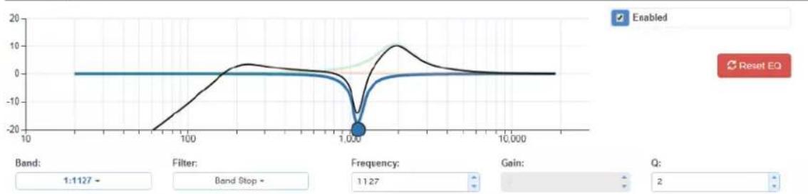
line
| Frequency | Value | | --------- | ----- | | 1 | -20 | | 10 | 0 | | 100 | 0 | | 1000 | -20 | | 10000 | 0 |- Enable – Click to activate the microphone.
- Phantom Power – Click to activate Phantom Power on the microphone.
- PreAmp Gain – Use the lever to adjust the preamp gain level of the microphone input. You can set the gain from 0 to +65dB in 1dB increments.
- Gain – Use the lever to adjust the gain level of the microphone input. You can set the gain from -24 to 24dB in 1dB increments.
- Equalizer – Click Enabled to turn on the equalizer settings. Use the options to set the Band, Filter, Frequency, Gain, and Q settings.
- Gating – Use the slider bar to adjust the Threshold setting (range: 0 to -60). Adjust the values in the boxes for the Attack, Release, Depth, and Hold Off settings (either enter values or use the arrows).
- Limiter – Use the slider bar to adjust the Threshold setting (range: 0 to -60). Adjust the values in the boxes for the Attack and Release settings (either enter values or use the arrows).
- Compression – Use the slider bar to adjust the Threshold setting (range: 0 to -60). Adjust the values in the boxes for the Attack, Release, and Ratio settings (either enter values or use the arrows).
- Show Audio Levels – Click to open a new window tab which displays the Level Meter for the microphone and audio input.
Outputs
- Port-Specific:
Port-Specific

- Encoding – PCM (read only).
- Test Tone Enable – Click Disable or Enable.
- Mute – Click Mute if desired. Changing the volume level will not un-mute the signal; however, the new volume level is saved and when the Mute button is deselected, the volume returns at the new level.
• Output Volume (0 to 100)
• Min/Max (0 to 100)
- Global:
Global
Test Tone Generator:
Off
- Test Tone Generator – from the drop-down list, select Off, 60Hz, 250Hz, 400Hz, 1kHz, 3kHz, 5kHz, 10kHz, Pink Noise, or White Noise.
Audio Group
Audio Groups enable you to create a group of audio ports in which all adjustments affect each individual port within the group. For example, if an audio group contains audio ports 1, 3, and 5 and you click Group Mute, the audio on ports 1, 3, and 5 become muted.
- Mode:
Mode
Group 1
- Select the group you want to work with from the drop-down menu.
- Adjustment:
Adjustment

bar
| Category | Value | | -------------- | ----- | | Group Volume | -100 | | Group Volume | -50 | | Group Volume | 0 | | Group Volume | -43 | | Balance | -20 | | Balance | 0 | | Balance | 20 | | Balance | 20 | | Sync Delay (ms)| 0 | | Sync Delay (ms)| 100 | | Sync Delay (ms)| 200 | | Sync Delay (ms)| 32 |- Output Format – Click Stereo or Mono.
- Group Mute – Click to mute the audio on all devices in the group.
• Group Volume (-100 to 0, left to right)
• Balance (-20 to 20, left to right) - Sync Delay (ms) (0 to 200).
Mix:
Mix
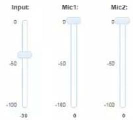
- Input – Use the slider to adjust the mix level of the audio input for the audio group.
- Mic1 and Mic2 – Use the sliders to adjust the mix level of the microphone for the audio group.
• 10-Band Parametric Equalizer:
10-Band Parametric Equalizer
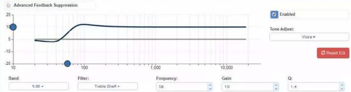
line
| Parameter | Value | | --------------- | ----- | | Band | 1 | | Filter | -20 | | Frequency | 58 | | Gain | 10 | | Q | 1.4 |- Advanced Feedback Suppression – Click to activate.
- Enabled – This check box must be selected before the Equalizer options are available. On reboot, the Enabled box always returns to the checked (default) state. To disable the Equalizer options over a reboot, set the "y" (vertical) vertex to 0 (zero).
- Tone Adjust – Use the drop-down box to select: Off, Voice, Music, or Movie (Tone Adjust is applied on top of any equalizer adjustments).
- Reset EQ – Click this button to reset the all of the Equalizer values.
- Blue Handles – Use the sliders (blue handles) to adjust Equalizer values.
- The following drop-down lists can also be used to adjust Equalizer values.
- Band – Numbered from 1 to 10.
- Filter – The options are Bell, Band Pass, Band Stop, High Pass, Low Pass, Treble Shelf, and Bass Shelf.
- Frequency – The adjustment range is from 20 to 20000 (Hz).
- Gain – The adjustment range is from -12 to 12.
- Q – The adjustment range depends on the filter selected:
Bell = 0.1 to 20
Band Pass = 0.1 to 20
Band Stop = 0.1 to 20
High Pass = 0.5 to 1.4
Low Pass = 0.5 to 1.4
Treble Shelf = 0.5 to 1
Bass Shelf = 0.5 to 1
- Ducking:
Ducking

line
| Metric | Value | | ---------------- | ----- | | Attenuation (dB) | 20 | | Release (ms) | 1000 | | Hold Time (ms) | 1000 |- Buttons at top – Click Off, Low, Medium, High, or Custom.
- L/R Mic – Use the slider bar to adjust (range: 0 to -60).
- Attack (ms), Attenuation (dB), Release (ms) and Hold Time (ms) – Adjust the values in the boxes (either enter values or use the arrows)
Selecting an Audio Test Tone
Selecting a test tone for your input source can help determine if you have your audio devices connected correctly. Perform these steps to select a test tone:
- Connect to your Presentation System via WebConsole.
- Select the Switcher tab.
- On the Switcher page, select the Configuration tab (see FIG. 95).

FIG. 95 WebConsole - Switcher Configuration page
- Select an output on the left side of the WebConsole.
- Click the Audio Out tab.
- In the Global area, use the Test Tone Generator menu to select a test tone.
- In the Port-Specific area, select Enable under Test Tone Enable.
Changing the Video Output Resolution
Perform these steps to change the video output resolution:
- Connect to your Presentation System via WebConsole.
- Pass your pointer device over the Switcher tab so the drop-down menu appears, then select Configuration. The Configuration page opens, and the Video Out tab appears by default (see FIG. 96).
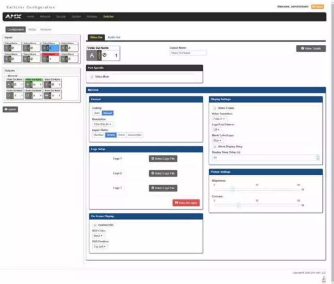
FIG. 96 WebConsole - Switcher Configuration page
- In the General section, use the Resolution drop-down menu to select a resolution. Your selection takes effect immediately.
Changing the Output Aspect Ratio
Perform these steps to change the output aspect ratio:
- Connect to your Presentation System via WebConsole.
- Pass your pointer device over the Switcher tab so the drop-down menu appears, then select Configuration. The Configuration page opens, and the Video Out tab appears by default (see FIG. 96).
- In the General section, click the button you want for the aspect ratio. Your selection takes effect immediately.
Selecting a Video Test Pattern
Selecting a test pattern for your input source can help determine if the displays are connected correctly. Perform these steps the select a test pattern:
- Connect to your Presentation System via WebConsole.
- Pass your pointer device over the Switcher tab so the drop-down menu appears, then select Configuration. The Configuration page opens, and the Video Out tab appears by default (see FIG. 96).
- In the Display Settings section, use the Logo/Test Pattern drop-down menu to select a test pattern or logo image to display on the video output.
Status Page
The Status page (FIG. 97) is used to check a number of the switcher's components and their states. The components (from top to bottom of page) display status for alarms, fan speed, and device temperature. Firmware versions and the current microphone mode are also available on this page. On this page, you can access options for locking the front panel, enabling the 70V amplifier, enabling auto switching, and muting all video displays.
![Switchker Configuration AMX Home Network Fax.org System Methods Switcher Configuration Status Window Fan Assets Power Assets Temperature Assets System Information Fan Speeds (SPWR) [422.0.8] Temperature (°C) [67.61.49] Switcher Firmware Version: v1 0.110 Master Firmware Version: v1 0.150 Device Firmware Version: v1 1.40 Add more switcher to Detroit Front Panel Lock Front Panel Ang 70x Enable Auto Switching Video Mode AI Microphone Mode Single Store Restore Copyright © 2005-2016 Ann LLC](/content/2026/05/982833/images/ba547f87f00040627f5929020af28f2a161b1f8f2b6c07f4d0a64199b1113081.jpg)
FIG. 97 Switcher - Status page (NCITE-813AC)
NCITE-813/813A devices have a slightly different version of this page with more system information available. The additional information you see on this page is available on the System - Info page on the NCITE-813AC (see the System - Info section on page 80 for more information.)

FIG. 98 Switcher - System page (NCITE-813/813A devices)
The following options appear on this page:
Switcher - System Page Options
| Lock Front Panel | Click to lock the front panel buttons and prohibit any manual switching or configuration by using the physical buttons on the device. |
| Amp 70v Enable Click to enable the | 70V amplifier on the device. |
| Auto Switching | Click to enable auto switching on the device. With Auto Switching, the device responds to the most recently added video input by switching the new input to display on the video output. |
| Video Mute All | Click to mute all video outputs connected to the device. Video mute results in a blank screen on the output displays. |
Windows Page
The Windows page (FIG. 99) is available when connected to an Incite Digital Video Presentation System. This page enables you to set options for transitioning between video outputs or setting up Picture in Picture (PIP).

Uspurge® 2006/01/04/13
FIG. 99 Windows page enables you to set transitions between video outputs
The following options appear on this page:
| Switcher - Windows Page Options | |
| Layout This area provides a visual | Indication of how the video will appear on the output device. This area is view-only. |
| View Mode Select a view mode by clicking one of the buttons. You can choose from Transition, PIP, and Window. With each selection, a different set of options appears | |
| Video Transition | Select a transition mode from the drop-down menu. The transition mode indicates how the current video selection will switch to a new video selection. You can choose from Diag Top Left, Diag Top Right, Diag Bottom Left, Diag Bottom Right, Horiz From Left, Horiz From Right, Vert From Top, Vert From Bottom, and Fade In. This option is only available when you select Transition as the view mode. |
| Window 1 Input | Choose a video input to set as the first window by using the drop-down menu. This option is only available when you select PIP or Window as the view mode. |
| Window 2 Input | Choose a video input to set as the second window by using the drop-down menu. This option is only available when you select PIP or Window as the view mode. |
| PIP Position Use the drop-down menu to choose the positioning of the two windows on the video output. You can choose from Top Left, Top Right, Bottom Left, and Bottom Right. With each position, Window 2 moves to selected location on the video output. This option is only available when you select PIP as the view mode. | |
| PIP Size Use the drop-down menu to choose the size of the smaller window on the video output. You can choose from Small, Medium, or Large. This option is only available when you select PIP as the view mode. | |
| Window Position Use the drop-down menu to choose the positioning of the two windows on the video output. You can choose from Side By Side or Top Bottom. This option is only available when you select Window as the view mode. | |
| Window Size Use the drop-down menu to choose the positioning of the two windows on the video output. You can choose from Top Large or Bottom Large. This option is only available when you select Window as the view mode and Top Bottom as the window position. | |
Firmware Upgrades
Overview
Upgrading firmware on Incite Presentation Systems involves downloading the latest firmware files from www.amx.com and using NetLinx Studio to transfer the files to a target device. The NetLinx Studio software application (available for free download from www.amx.com) provides the ability to transfer KIT firmware files to a NetLinx device.
NOTE: To upgrade the firmware via WebConsole for the NCITE-813/813A, see the Updating Firmware on NCITE-813/813Asection on page 106.
To upgrade the firmware for the NCITE-813AC, use the Online Device tree in NetLinx Studio to view the firmware files currently loaded on the Digital Video Presentation System. FIG. 100 shows an example Online Tree:

FIG. 100 NetLinx Studio - Sample Online Tree
Incite Digital Video Presentation Systems contain three devices (NX Master, Device Controller, and A/V Switcher/Scaler), each of which requires a separate Kit file. These three devices must be kept at compatible firmware versions for proper operation. Therefore, all three files should be used when upgrading any firmware associated with the digital video presentation system.
| Incite Digital Video Presentation Systems - Firmware Files | |
| NX Master Firmware (NCITE-813AC only) | The on-board Master is listed first in the Online Tree as “00000 NCITE-813AC Master (”)”“00000” represents Device ID 0, which is reserved for the MasterThe number in parenthesis is the current Master firmware version. |
| Device Controller Firmware (NCITE-813AC only) | The Device Controller is listed next as “05001 NCITE-813AC Controller ()”“05001” represents Device ID 5001, which is reserved for the Device Control ports.The number in parenthesis is the current Device Controller firmware version. |
| A/V Switcher/Scaler Firmware | The A/V Switcher/Scaler is listed third as “05002 NCITE-813AC ()”“05002” represents Device ID 5002, which is reserved for the A/V Switcher/Scaler.The number in parenthesis is the current Device Controller firmware version. |
Before You Start
Perform the following steps before upgrading your firmware version:
- Verify you have the latest version of NetLinx Studio on your PC. Use the Web Update option in NetLinx Studio's Help menu to obtain the latest version. Alternatively, go to www.amx.com and login as a Dealer to download the latest version.
- Go to www.amx.com and download the latest Firmware file. Firmware files are available to download from www.amx.com - on the product's page in the online catalog.
- Verify that an Ethernet cable is connected from the digital video presentation switcher to the Ethernet Hub.
- Verify that the digital video presentation switcher is powered On.
- Determine the Device Number assigned to the target digital video presentation switcher.
- By default, the Device Number assigned to the digital video presentation switcher is 0 (zero). (The Master device number is always 0 and cannot be changed.)
- The Device Number can be viewed on the WebConsole - System Devices page.
- Launch NetLinx Studio and open the Online Device Tree.
Verifying the Current Firmware Version
Use the Online Tree in NetLinx Studio (see FIG. 100) to verify which version of each firmware file is currently installed.
- In NetLinx Studio, click on the Online Tree tab (in the Workspace Bar) to view the devices on the System.
- Click Display and select Refresh System Online Tree from the context menu that appears. This establishes a new connection to the System and populates the device tree with devices on that system.
- After the Communication Verification dialog box indicates active communication between the PC and the Central Controller, verify the Central Controller and associated devices are listed in the Online Tree.
- Check the appropriate product page on www.amx.com for the latest NX Master, Device Controller, and A/V Switcher/Scaler firmware files for your device.
If necessary, follow the procedures outlined in the following sections to obtain these firmware (*.kit) files from www.amx.com and then transfer the new firmware files to the device.
Downloading the Latest Firmware Files from www.amx.com
Below is a table outlining the Master, Device, and Switcher firmware (*.kit) files used by Incite Presentation Systems:
Master Firmware Kit File Usage for Incite Digital Video Presentation Systems
| NCITE-813/813A/813AC | Master Firmware: SW1901_1X-NCITE_FW_vx_xxx.kit (NCITE-813AC only) |
| Device Firmware: SW2106_1X-NCITE_Device_v1_x_xx.kit (NCITE-813ac ONLY) | |
| A/V Switcher/Scaler Firmware: SW1906_1X-NCITE_Switcher_v1_x_xx.kit |
Downloading Incite Firmware Files on www.amx.com
Visit the appropriate product page on www.amx.com for the latest NX Master and Device Controller firmware (*.kit) files for your Presentation System. Firmware file links are available along the right-side of the catalog page (FIG. 101):
Firmware Files
NX Series D/VX-325x/225x
Master Firmware
ZIP | 74.86 MB | v 1.3.47
NX Series D/VX-325x/225x
Device Firmware
FIG. 101 www.amx.com - sample Enova DVX firmware file links
Firmware files are bundled in a ZIP file, along with a Readme.TXT file that provides details on this firmware release.
- Accept the AMX Licensing Agreement.
- Download the ZIP file and unzip the contents to a known location.
Required Order of Firmware Updates for Incite Digital Presentation Systems
Upgrade firmware in the following order:
- First, upgrade the A/V Switcher/Scaler firmware.
- When that process is complete, upgrade the Master firmware.
- When that process is complete, upgrade the Device firmware.
NOTE: ALWAYS consult the Readme.TXT file bundled with the firmware file for any special instructions before upgrading to a newer firmware version. If no specifics are provided, use the order provided above.
Sending Firmware (\*.KIT) Files to the Device
Use the Firmware Transfers options in the Tools menu to update the firmware on the device. NetLinx Devices such as Incite Presentation Systems use KIT files for firmware upgrades.
NOTE: A Kit file (*.KIT) is a package of several files, all of which are required to upgrade the firmware, and are available online via www.amx.com. Firmware download links are provided in the relevant product page.
- The Online Device Tree (Online Tree tab of the Workspace Window) displays information about each online device, including the current firmware version.
- Before attempting to upgrade the firmware, you must have the appropriate Kit file for your device.
The digital video presentation switcher contains two devices which each require a separate Kit file. These three devices must be kept at compatible firmware versions for proper operation.
• Device ID 0: NetLinx Master Controller
- Default Device ID 5001: Device Control Ports
To update NetLinx firmware:
- Choose Tools > Firmware Transfers > Send to NetLinx Device to open the Send To NetLinx Device dialog box (FIG. 102).

FIG. 102 Send to NetLinx Device dialog box (NetLinx Studio)
- Click the Browse (...) button to navigate to the target directory in the Browse For Folder dialog box (FIG. 103).

FIG. 103 Browse For Folder dialog box (NetLinx Studio)
- The selected directory path is displayed in the Send To NetLinx Device dialog (Location text box).
- Assuming that the specified target directory contains one or more KIT files, the KIT files in the selected directory are displayed in the Files list box, with the file's last modified date and time (FIG. 104).

FIG. 104 Send to NetLinx Device dialog box (NetLinx Studio)
- Select the appropriate *.KIT file from the Files list.
NOTE: Always update Incite devices in the following order:
Device 5002 (AV Switcher/Scaler)
Device 0 (NetLinx Master, if available)
Device 5001 (Integrated Control Ports)
ALWAYS consult the Readme.TXT file bundled with the firmware file for any special instructions before upgrading to a newer firmware version. If no specifics are provided, use the order provided above.
- Enter the Device ID number of the integrated device to be upgraded in the Device text box and the System ID
numbers for the digital video presentation switcher in the System text box. ● The device number of the NetLinx Master is 0.
- By default, the Device number assigned to the integrated control ports is 5001.
-
Use the Online Device Tree to determine the device's assigned IDs, if it has been changed.
-
Review the File, Connection, Address, and Target Device information before you send.
-
Click the Send button. You can watch the progress of the transfer in the Send to NetLinx Device dialog box.
NetLinx Studio transfers the files to the digital video presentation switcher and then tells it to reboot. After it reboots, the digital video presentation switcher actually goes through the upgrade process.
- During the upgrade process, the Status LED blinks, and the digital video presentation switcher stays offline.
- Once the upgrade is complete, the LED will stop blinking and the digital video presentation switcher will be online.
- Repeat the firmware update process for the next device until all devices are updated.
NOTE: Upgrading the Master or device firmware can take several minutes.
CAUTION: If for any reason your Kit file transfer should fail, continue to retry the transfer until you are successful. DO NOT reboot the digital video presentation switcher, or change connections until the transfer is complete. Failure to complete this operation successfully may require a factory repair of the digital video presentation switcher.
Additional Documentation
For additional information on using NetLinx Studio, refer to the NetLinx Studio online help and Instruction Manual (available at www.amx.com).
Updating Firmware on NCITE-813/813A
The NCITE-813/813A Presentation Systems do not contain NetLinx devices, so you cannot update the device firmware via NetLinx Studio. Instead, you can update the firmware for these devices by accessing the WebConsole for the device (see the Using a Web Browser section on page 52 for more information.)
Perform these steps to update the firmware on an NCITE-813/813A Presentation System:
- Download the latest .kit file from www.amx.com and save the file to a location that is accessible to the Presentation System.
- Access the WebConsole for the Presentation System (see page 52).
- Select Switcher from the System Configuration menu that runs across the top of the page. The Switcher page appears.
- Select Status to view the status information for the Presentation System (FIG. 105).

FIG. 105 Switcher Status page
- Click Update Firmware Kit. A file windows opens which you can use to navigate to the .kit file.
- Select the .kit file and click Open. The firmware update begins.
Programming
Overview
The chapter defines all programming commands available for the Incite Presentation Systems.
NOTE: This chapter lists programming commands unique to Incite Presentation Systems. Please consult the WebConsole & Programming Guide for NX-Series Controllers for more details on NetLinx controller commands. The NCITE-813AC supports all commands compatible with the NX-2200 controller.
NetLinx Channels and Levels
The following sections define the NetLinx channels and levels available for the NCITE-813AC:
NCITE-813AC NetLinx Channels
| NCITE-813AC NetLinx Channels | ||
| Channel Ports Description | ||
| 24 1-4 Volume Up | ||
| 25 1-4 Volume Down | ||
| 26 1-4 Volume Mute Cycle | ||
| 32 1-4 Switches video input 1 to the video output | ||
| 32 1-4 Switches video input 2 to the video output | ||
| 33 1-4 Switches video input 3 to the video output | ||
| 34 1-4 Switches video input 4 to the video output | ||
| 35 1-4 Switches video input 5 to the video output | ||
| 36 1-4 Switches video input 6 to the video output | ||
| 37 1-4 Switches video input 7 to the video output | ||
| 38 1-4 Switches video input 8 to the video output | ||
| 41 1-4 Switches audio input 1 to the video output | ||
| 42 1-4 Switches audio input 2 to the video output | ||
| 43 1-4 Switches audio input 3 to the video output | ||
| 44 1-4 Switches audio input 4 to the video output | ||
| 45 1-4 Switches audio input 5 to the video output | ||
| 46 1-4 Switches audio Input 6 to the video output | ||
| 70 1-4 Video Output Enable | ||
| 71 1-2 Mic Enable (Mono) | ||
| 83 1-8 Video In Phase Ramp Up | ||
| 84 1-8 Video In Phase Ramp Down | ||
| 132 1-8 Video In V-Shift Ramp Up | ||
| 133 1-8 Video In V-Shift Ramp Down | ||
| 134 1-8 Video In H-Shift Ramp Up | ||
| 135 1-8 Video In H-Shift Ramp Down | ||
| 140 1-6 Gain Up | ||
| 141 1-6 Gain Down | ||
| 143 1-6 Gain Mute | ||
| 164 1-4 Balance Ramp Up | ||
| 165 1-4 Balance Ramp Down | ||
| 199 1-4 Volume Mute Set and State | ||
| 209 1-8 Video In Auto Adjust | ||
| 210 1-4 Video Mute State | ||
| 213 1-4 Video Freeze State | ||
| 216 1 Fan Alarm | ||
| Channel Ports Description | ||
| 217 1 Temperature Alarm | ||
| 218 1 Power | Alarm | |
| 219 | Audio Group Mute | |
| 234 1-4 OSD | State | |
Channel Video Switching
To switch video via channels, the channel must be turned ON (as opposed to pulsing the channel). For example, turn on Channel 31 on Port 1 for Input 1 to output video.
These channels are mutually exclusive:
- Turning On another channel will change input and turn off the last channel.
- Turning Off a selected channel will select input none.
- Pulsing any channel will set input to none as it turns on, and then back off the channel pulsed.
NCITE-813AC NetLinx Levels
The following table list the NetLinx levels for the NCITE-813AC:
NCITE-813AC NetLinx Levels
| Level Ports Range Function | |||
| 1 1-4 0-100 | Output volume | ||
| 2 1-4 (-20)-(20) Audio Output Balance | |||
| 5 1-6 (-24)-(24) Audio Input Gain | |||
| 8 | 1 | Temperature (read-only level) | |
| 20 1-4 0-100 | Video Output | Brightness | |
| 22 | 1-4 0-100 | Video Output Contrast | |
| 31 | 1-4 (-12)-(12) | Audio EQ Band 1 | |
| 32 | 1-4 (-12)-(12) | Audio EQ Band 2 | |
| 33 | 1-4 (-12)-(12) | Audio EQ Band 3 | |
| 34 | 1-4 (-12)-(12) | Audio EQ Band 4 | |
| 35 | 1-4 (-12)-(12) | Audio EQ Band 5 | |
| 36 | 1-4 (-12)-(12) | Audio EQ Band 6 | |
| 37 | 1-4 (-12)-(12) | Audio EQ Band 7 | |
| 38 | 1-4 (-12)-(12) | Audio EQ Band 8 | |
| 39 | 1-4 (-12)-(12) | Audio EQ Band 9 | |
| 40 | 1-4 (-12)-(12) | Audio EQ Band 10 | |
| 41 | 1-4 (-100)-0 | Audio Program Source Mixing Level | |
| 42 | 1-4 (-100)-0 | Audio Line Mic 1 Mixing Level | |
| 43 | 1-4 (-100)-0 | Audio Line Mic 2 Mixing Level | |
| 50 | 1-4 | 0-8 | Video Switching: Level 50 for each output port 1-4 will be a value from 0 to 8 indicating which video input is switched to that output. Changing the value of this level will result in a video switch. |
| 51 | 1-4 | 0-6 | Audio Switching: Level 51 for each output port 1-4 will be a value from 0 to 6 indicating which audio input is switched to that output. Changing the value of this level will result in an audio switch. |
| 52 | 1-3 | 0-65 | Audio Mic PreAmp Gain |
| 53 | 1-3 | (-24)-(24) Audio Mic Gain | |
| 61 | 1-3 | (-12)-(12) Mic EQ Band 1 | |
| 62 | 1-3 | (-12)-(12) Mic EQ Band 2 | |
| 63 | 1-3 | (-12)-(12) Mic EQ Band 3 | |
| 65 | 1-6 | (-100)-0 | Output Audio Group Volume |
SEND\_COMMANDS
The commands listed in the following sections are for the switcher only. For generic NetLinx commands, see the NetLinx Integrated Controllers WebConsole and Programming Guide.
- The commands derive their input/output port addressing from the target D:P:S.
- INPUT ports range from 1-14 for Audio and from 1-8 for Video. HDMI inputs are capable of carrying both digital audio and video signals
- The extra ports 1 and 2 on the Audio subsystem represent MIC1 and MIC2 respectively.
- There are four Audio output ports (05002:1:0, 05002:2:0, 05002:3:0, and 05002:4:0).
- Audio Output Port #1 is the Main Amp Output and most audio commands are addressed to this port.
- Audio Output Ports 2-4 are the Line Outputs and normally track the Main Amp Output port with small exceptions.
- There are four Video output ports (05002:1:0, 05002:2:0, 05002:3:0, and 05002:4:0).
- Input and Output functional distinctions are disambiguated from the overlapped port numbers by combining them with the command name.
Port Functionality Mapping
The following table lists the port functionality mapping for the audio/video ports on the NCITE-813AC:
| Port Functionality Mapping | ||
| Port Number Description Address | ||
| 1 Audio/Video Input 1 05002:1:0 | ||
| 2 Audio/Video Input 2 05002:2:0 | ||
| 3 Audio/Video Input 3 05002:3:0 | ||
| 4 Audio/Video Input 4 05002:4:0 | ||
| 5 Audio/Video Input 5 05002:5:0 | ||
| 6 Audio/Video Input 6 05002:6:0 | ||
| 7 Audio/Video Input 7 05002:7:0 | ||
| 8 Audio/Video Input 8 05002:8:0 | ||
| 11 Audio Input 11 05002:11:0 | ||
| 12 Audio Input 12 05002:12:0 | ||
| 13 Audio Input 13 05002:13:0 | ||
| 14 Audio Input 14 05002:14:0 | ||
| 1 Mic In 1 05002:1:0 | ||
| 2 Mic In 2 05002:2:0 | ||
| 1 Audio Output 1 (Amplified) 05002:1:0 | ||
| 2 Audio Output 2 05002:2:0 | ||
| 3 Audio Output 3 05002:3:0 | ||
| 4 Audio Output 4 | 05002:4:0 | |
| 1 Audio/Video Output1 | 05002:1:0 | |
| 2 Audio/Video Output2 | 05002:2:0 | |
| 3 Audio/Video Output3 | 05002:3:0 | |
| 4 Audio/Video Output4 | 05002:4:0 | |
Port Numbers
The following table lists the port numbers for the NCITE-813AC:
| NCITE-813AC Port Numbers | |||||
| Model | RS-232 | RS-422/485 | IR/Serial | I/O | Relay |
| NCITE-813AC | 2-4 | 1 | 11-14 | 22 | 21 |
AUDIO SEND\_COMMANDs
The following table lists the audio SEND_COMMANDs available for the NCITE-813AC:Video SEND_COMMANDs
| Audio SEND_COMMANDs | |
| AIO | Switches audio input portto audio output port. Syntax:SEND_COMMAND ''AI''Variables:input = The source audio input number.output = The audio output port number to switch to.Example:SEND_COMMAND SWITCHER, ''AT201''Switch audio input port #2 to audio output #1. |
| ?AUDIN_COMPRESSION | Requests the setting of compression for the audio port addressed by the D:P:S. Syntax:SEND_COMMAND, ''?AUDIN_COMPRESSION''Example:SEND_COMMAND AUDIO_INPUT_1, ''?AUDIN_COMPRESSION''Returns a COMMAND string of the form:AUDIN_COMPRESSION- |
| AUDIN_COMPRESSION | Sets the setting of compression for the audio port addressed by the D:P:S. Syntax:SEND_COMMAND, ''AUDIN_COMPRESSION-''Variable:setting =off, low, medium, high, customExample:SEND_COMMAND AUDIO_INPUT_1, ''AUDIN_COMPRESSION-high''Sets the compression setting of the audio input port (#1 based on D:P:S) to high. |
| ?AUDIN_COMPRESSION_ATTACK | Requests the compression attack for the audio port. Syntax:SEND_COMMAND, ''?AUDIN_COMPRESSION_ATTACK''Example:SEND_COMMAND AUDIO_1, ''?AUDIN_COMPRESSION_ATTACK''Returns a COMMAND string of the form:AUDIN_COMPRESSION_ATTACK- |
| AUDIN_COMPRESSION_ATTACK | Sets the duration of the attack phase while compressing for the audio port addressed by the D:P:S. Syntax:SEND_COMMAND, ''AUDIN_COMPRESSION_ATTACK-''Variable:attack = 1 to 2000Example:SEND_COMMAND AUDIO_INPUT_1, ''AUDIN_COMPRESSION_ATTACK-200''Sets the compression attack for the audio port (#1 based on the D:P:S) to 200. |
| ?AUDIN_COMPRESSION_RATIO | Requests the compression ratio for the audio port. Syntax:SEND_COMMAND, ''?AUDIN_COMPRESSION_RATIO''Example:SEND_COMMAND AUDIO_INPUT_1, ''?AUDIN_COMPRESSION_RATIO''Returns a COMMAND string of the form:AUDIN_COMPRESSION_RATIO- |
| AUDIN_COMPRESSION_RATIO | Sets the ratio while compressing for the audio input port addressed by the D:P:S. Syntax:SEND_COMMAND, ''AUDIN_COMPRESSION_RATIO-''Variable:ratio = 1 to 20Example:SEND_COMMAND AUDIO_INPUT_1, ''AUDIN_COMPRESSION_RATIO-5'' |
| Audio SEND_COMMANDs (Cont.) | |
| ?AUDIN_COMPRESSION_RELEASE | Requests the compression release for the audio port Syntax:SEND COMMAND, ''?AUDIN_COMPRESSION_RELEASE''Example:SEND_COMMAND AUDIO_1, ''?AUDIN_COMPRESSION_RELEASE''Returns a COMMAND string of the form:AUDIN_COMPRESSION_RELEASE-- |
| AUDIN_COMPRESSION_RELEASE | Sets the duration of the release phase while compressing for the audio port addressed by the D:P:S. Syntax:SEND COMMAND, ''AUDIN_COMPRESSION_RELEASE--''Variable:release = 1 to 5000Example:SEND_COMMAND AUDIO_INPUT_1, ''AUDIN_COMPRESSION_RELEASE-200''Sets the compression release for the audio port (#1 based on the D:P:S) to 200. |
| ?AUDIN_COMPRESSION_THRESH | Requests the compression threshold for the audio port. Syntax:SEND_COMMAND, ''?AUDIN_COMPRESSION_THRESH''Example:SEND_COMMAND AUDIO_INPUT_1, ''?AUDIN_COMPRESSION_THRESH''Returns a COMMAND string of the form:AUDIN_COMPRESSION_THRESH-- |
| AUDIN_COMPRESSION_THRESH | Sets the threshold while compressing for the audio input port addressed by the D:P:S. Syntax:SEND_COMMAND, ''AUDIN_COMPRESSION_THRESH--''Variable:threshold = 0 to -60 in dBExample:SEND_COMMAND AUDIO_INPUT_1, ''AUDIN_COMPRESSION_THRESH--10''Sets the threshold while compressing for the selected audio input port (#1 based on D:P:S) to -10dB. |
| ?AUDIN_DIGITAL | Requests the format of the audio port addressed by the D:P:S. Syntax:SEND_COMMAND, ''?AUDIN_DIGITAL''Example:SEND_COMMAND AUDIO_INPUT_1, ''?AUDIN_DIGITAL''Returns a string of the form:AUDIN_DIGITAL-- |
| AUDIN_DIGITAL | Sets the format for the audio input port addressed by the D:P:S. Syntax:SEND_COMMAND, ''AUDIN_DIGITAL--''Variable:format = PCM-2ch, PCM-8ch, AC3, DTS, MPEG, AAC, TrueHD, DTSHDExample:SEND_COMMAND AUDIO_INPUT_1, ''AUDIN_DIGITAL-AAC''Sets the audio format for the audio input port (#1 based on D:P:S) to AAC. |
| ?AUDIN_GAIN | Requests the gain of the audio port addressed by the D:P:S. Syntax:SEND_COMMAND, ''?AUDIN_GAIN''Example:SEND_COMMAND AUDIO_INPUT_1, ''?AUDIN_GAIN''Returns a COMMAND string of the form:AUDIN_GAIN-- |
| AUDIN_GAIN | Sets the gain of the audio port addressed by the D:P:S to. Syntax:SEND_COMMAND, ''AUDIN_GAIN--''Variable:gain = -24 to 24 in dBExample:SEND_COMMAND AUDIO_INPUT_1, ''AUDIN_GAIN-12''Sets the gain of the audio input port (#1 based on D:P:S) to 12 dB. |
| ?AUDIN_STEREO | Requests to see if the audio port addressed by the D:P:S has the stereo setting enabled or disabled. Syntax:SEND_COMMAND, "'?AUDIN_STEREO"Example:SEND_COMMAND AUDIO_INPUT_1,"'?AUDIN_STEREO"Returns a COMMAND string of the form:AUDIN_STEREO- |
| AUDIN_STEREO | Enables or disables the stereo setting on the audio port addressed by the D:P:S. If enabled, the stereo setting is on. If disabled, the stereo setting is off, which means it is mono. Syntax:SEND_COMMAND,"'?AUDIN_STEREO-''Variable:setting = enable or disableExample:SEND_COMMAND AUDIO_INPUT_1,"'?AUDIN_STEREO-enable" |
| ?AUDMIC_COMPRESSION | Requests the setting of compression for a microphone. Syntax:SEND_COMMAND,"'?AUDMIC_COMPRESSION"Example:SEND_COMMAND MICROPHONE_1,"'?AUDMIC_COMPRESSION"Returns a COMMAND string of the form:AUDMIC_COMPRESSION- |
| AUDMIC_COMPRESSION | Sets the setting of compression of the microphone port addressed by the D:P:S to. Syntax:SEND_COMMAND,"'?AUDMIC_COMPRESSION-''Variable:setting = off, low, medium, high, customExample:SEND_COMMAND MICROPHONE_1,"'?AUDMIC_COMPRESSION-high"Sets the compression for the microphone port (#1 based on D:P:S) to high. |
| ?AUDMIC_COMPRESSION_ATTACK | Requests the duration of the attack phase while compressing for a microphone. Syntax:SEND_COMMAND,"'?AUDMIC_COMPRESSION_ATTACK"Example:SEND_COMMAND MICROPHONE_1,"'?AUDMIC_COMPRESSION_ATTACK"Returns a COMMAND string of the form:AUDMIC_COMPRESSION-ATTACK- |
| AUDMIC_COMPRESSION_ATTACK | Sets the duration of the attack phase while compressing for the microphone port addressed by the D:P:S. Syntax:SEND_COMMAND,"'?AUDMIC_COMPRESSION_ATTACK-''Variable:attack = 1 to 2000Example:SEND_COMMAND MICROPHONE_1,"'?AUDMIC_COMPRESSION_ATTACK-200"Sets the compression attack for the microphone port (#1 based on the D:P:S) to 200. |
| ?AUDMIC_COMPRESSION_RATIO | Requests the ratio while compressing for a microphone. Syntax:SEND_COMMAND,"'?AUDMIC_COMPRESSION_RATIO"Example:SEND_COMMAND MICROPHONE_1,"'?AUDMIC_COMPRESSION_RATIO"Returns a COMMAND string of the form:AUDMIC_COMPRESSION-RATIO- |
| AUDMIC_COMPRESSION_RATIO | Sets the ratio while compressing for the microphone port addressed by the D:P:S. Syntax:SEND_COMMAND,"'?AUDMIC_COMPRESSION_RATIO-''Variable:ratio = 1 to 20Example:SEND_COMMAND MICROPHONE_1,"'?AUDMIC_COMPRESSION_RATIO-5"Sets the compression ratio for the microphone port (#1 based on the D:P:S) to 5. |
| ?AUDMIC_COMPRESSION_RELEASE | Requests the duration of the release phase while compressing for a microphone. Syntax:SEND COMMAND,,"?AUDMIC_COMPRESSION_RELEASE'"Example:SEND_COMMAND MIC_1,"'?AUDMIC_COMPRESSION_RELEASE'"Returns a COMMAND string of the form:AUDMIC_COMPRESSION-RELEASE- |
| AUDMIC_COMPRESSION_RELEASE | Sets the duration of the release phase while compressing for the microphone port addressed by the D:P:S. Syntax:SEND_COMMAND,"'AUDMIC_COMPRESSION_RELEASE-'''Variable:release = 1 to 5000Example:SEND_COMMAND MICROPHONE_1,"'AUDMIC_COMPRESSION_RELEASE-200'"Sets the compression release for the microphone port (#1 based on the D:P:S) to 200. |
| ?AUDMIC_COMPRESSION_THRESH | Requests the threshold while compressing for a microphone. Syntax:SEND_COMMAND,"'?AUDMIC_COMPRESSION_THRESH'"Example:SEND_COMMAND MIC_1,"'?AUDMIC_COMPRESSION_THRESH'"Returns a COMMAND string of the form:AUDMIC_COMPRESSION-THRESH- |
| AUDMIC_COMPRESSION_THRESH | Sets the threshold while compressing for the microphone port addressed by the D:P:S. Syntax:SEND_COMMAND,"'AUDMIC_COMPRESSION_THRESH-'''Variable:thresh = 0 to -60Example:SEND_COMMAND MICROPHONE_1,"'AUDMIC_COMPRESSION_THRESH-20'"Sets the compression threshold for the microphone port (#1 based on the D:P:S) to -20. |
| AUDMIC_DUCK_ATTACK | Sets the duration of the attack phase while ducking for the microphone port addressed by the D:P:S. Syntax:SEND_COMMAND,"'AUDMIC_DUCK_ATTACK-'''Variable:attack = 1 to 2000Example:SEND_COMMAND MICROPHONE_1,"'AUDMIC_DUCK_ATTACK-200'"Sets the ducking attack for the microphone port (#1 based on the D:P:S) to 200. |
| AUDMIC_DUCK_HOLD | Sets the duration of the hold phase while ducking for the microphone port addressed by the D:P:S. Syntax:SEND_COMMAND,"'AUDMIC_DUCK_HOLD-'''Variable:hold = 0 to 2000Example:SEND_COMMAND MICROPHONE_1,"'AUDMIC_DUCK_HOLD-200'"Sets the ducking hold for the microphone port (#1 based on the D:P:S) to 200. |
| AUDMIC_DUCK_LEVEL | Sets the level while ducking for the microphone port addressed by the D:P:S. Syntax:SEND_COMMAND,"'AUDMIC_DUCK_LEVEL-'''Variable:level = 0 to 20Example:SEND_COMMAND MICROPHONE_1,"'AUDMIC_DUCK_LEVEL-4'"Sets the ducking level for the microphone port (#1 based on the D:P:S) to 4. |
| AUDMIC_DUCK_RELEASE | Sets the duration of the release phase while ducking from the microphone port addressed by the D:P:SSyntax:SEND_COMMAND, ''AUDMIC_DUCK_RELEASE-''Variable:release = 10 to 5000Example:SEND_COMMAND MICROPHONE 1, ''AUDMIC_DUCK_RELEASE-200''Sets the ducking release for the microphone port (#1 based on the D:P:S) to 200. |
| ?AUDMIC_EQ_CF | Requests the frequency for the specified microphone band of the equalizer for the microphone port addressed by the D:P:SSyntax:SEND_COMMAND, ''?AUDMIC_EQ_CF-''Variables:band = 1..3 on the microphone inputs.Example:SEND_COMMAND MIC_1, ''?AUDMIC_EQ_CF-1''Returns a COMMAND string of the form:AUDMIC_EQ_CF-,, |
| AUDMIC_EQ_CF | Sets the frequency for the specified microphone band of the equalizer for the microphone port addressed by the D:P:SSyntax:SEND_COMMAND, ''AUDMIC_EQ_CF-,,Variables:band = 1..3 on the microphone inputs.frequency = 20 to 20,000 In Hz.Example:SEND_COMMAND MICROPHONE 1, ''AUDMIC_EQ_CF-1,1000''Sets the frequency for the first band of the equalizer for the selected microphone port (#1 based on D:P:S) to be 1000. |
| ?AUDMIC_EQ_FT | Requests the filter type of the specified microphone band of the equalizer for the microphone port addressed by the D:P:SSyntax:SEND_COMMAND, ''?AUDMIC_EQ_PT-''Variable:band = 1..3 on the microphone inputs.Example:SEND_COMMAND MIC_1, ''?AUDMIC_EQ_FT-1''Returns a COMMAND string of the form:AUDMIC_EQ_FT-,, |
| AUDMIC_EQ_FT | Set the filter type of any of the specified microphone band of the equalizer for the microphone port addressed by the D:P:SSyntax:SEND_COMMAND, ''AUDMIC_EQ_FT-,,Variables:band = 1..3 on the microphone inputs.type = bell, band pass, band stop, high pass, low pass, treble shelf, bass shelfExample:SEND_COMMAND MICROPHONE_1, ''AUDMIC_EQ_FT-1,band pass''Sets the filter type for the first band of the equalizer for the selected microphone port (#1 based on D:P:S) to band pass. |
| ?AUDMIC_EQ_GAIN | Requests the gain on the microphone equalizer setting of bandon the output audio port addressed by the D:P:SSyntax:SEND_COMMAND, ''?AUDMIC_EQ_GAIN-''Variable:band = 1..3 on the microphone inputs.Example:SEND_COMMAND MIC_1, ''?AUDMIC_EQ_GAIN-1''Returns a COMMAND string of the form:AUDMIC_EQ_GAIN-,, |
| Audio SEND_COMMANDs (Cont.) | |
| AUDMIC_EQ_GAIN | Sets the gain on the microphone equalizer bandon the output audio port addressed by the D:P:S to.<value>.Syntax:SEND_COMMAND,, ''AUDMIC_EQ_GAIN-,,''Variables:band = 1..3 on the microphone inputs.value = -12..12. The units are in dB.Example:SEND_COMMAND MIC_1, ''AUDMIC_EQ_GAIN-1,8''Sets the gain on microphone band #1 of microphone 1 equalizer to 8.SEND_COMMAND MIC_2, ''AUDMIC_EQ_GAIN-3,10''Sets the gain on microphone band #3 of microphone 2 equalizer to 10. |
| ?AUDMIC_EQ_Q | Requests the quality factor (Q) for the specified microphone band of the equalizer for the microphone port addressed by the D:P:SSyntax:SEND_COMMAND,, ''AUDMIC_EQ_Q-''Variable:band = 1..3 on the microphone inputs.Example:SEND_COMMAND MIC_1, ''AUDMIC_EQ_Q-1''Returns a COMMAND string of the form:AUDMIC_EQ_Q-,, |
| AUDMIC_EQ_Q | Sets the quality factor (Q) for the specified microphone band of the equalizer for the microphone port addressed by the D:P:SSyntax:SEND_COMMAND,, ''AUDMIC_EQ_Q-,,''Variables:band = 1 to 3 on the microphone inputs.factor = range depends on filter type (set by AUDMIC_EQ_FT)Bell: range is 0.1 - 20.0Band Pass:range is 0.1 - 20.0Band Stop:range is 0.1 - 20.0High Pass:range is 0.5 - 1.4Low Pass:range is 0.5 - 1.4Treble Shelf:range is 0.5 - 1.0Bass Shelf:range is 0.5 - 1.0Example:SEND_COMMAND MICROPHONE_1, ''AUDMIC_Q-1,1''Sets the quality factor for the first band of the equalizer for the selected microphone port (#1 based on D:P:S) to 1. |
| ?AUDMIC_GAIN | Requests the gain setting for the microphoneSyntax:SEND_COMMAND,, ''AUDMIC_GAIN''Example:SEND_COMMAND MICROPHONE_1, ''AUDMIC_GAIN''Returns a COMMAND string of the form:AUDMIC_GAIN- |
| AUDMIC_GAIN | Sets the gain of the microphone port addressed by the D:P:S to.<value>.Syntax:SEND_COMMAND,, ''AUDMIC_GAIN-''Variable:gain = -24 to 24 in dBExample:SEND_COMMAND MICROPHONE_1, ''AUDMIC_GAIN-3''Sets the gain for the microphone port (#1 based on the D:P:S) to 3dB. |
| ?AUDMIC_GATING | Requests the setting of gating of a microphone Syntax:SEND COMMAND, "‘?AUDMIC GATING’"Example:SEND_COMMAND MICROPHONE_1, “‘?AUDMIC GATING’”Returns a COMMAND string of the form:AUDMIC_GATING- |
| AUDMIC_GATING | Sets the setting of gating of the microphone port addressed by the D:P:S to. Syntax:SEND_COMMAND, "‘AUDMIC GATING-’”Variable:setting = off, low, medium, high, customExample:SEND_COMMAND MICROPHONE_1, “‘AUDMIC GATING-low’”Sets the gating for the microphone port (#1 based on D:P:S) to low. |
| ?AUDMIC_GATING_ATTACK | Requests the duration of the attack phase while gating from the microphone port addressed by the D:P:SSyntax:SEND_COMMAND, “‘?AUDMIC GATING ATTACK’”Example:SEND_COMMAND MIC_1, “‘?AUDMIC GATING ATTACK’”Returns a string of the form:AUDMIC_GATING_ATTACK= |
| AUDMIC_GATING_ATTACK | Sets the duration of the attack phase while gating from the microphone port addressed by the D:P:SSyntax:SEND_COMMAND, “‘AUDMIC GATING ATTACK-’”Variable:attack = 1 to 2000Example:SEND_COMMAND MICROPHONE_1, “‘AUDMIC GATING ATTACK-200’”Sets the gating attack for the microphone port (#1 based on the D:P:S) to 200. |
| ?AUDMIC_GATING_DEPTH | Requests the depth setting while gating from the microphone port addressed by the D:P:SSyntax:SEND_COMMAND, “‘?AUDMIC GATING DEPTH’”Example:SEND_COMMAND MIC_1, “‘?AUDMIC GATING DEPTH’”Returns a string of the form:AUDMIC_GATING_DEPTH= |
| AUDMIC_GATING_DEPTH | Sets the depth while gating from the microphone port addressed by the D:P:SSyntax:SEND_COMMAND, “‘AUDMIC GATING_DEPTH-’”Variable:depth = 0 to 20Example:SEND_COMMAND MICROPHONE_1, “‘AUDMIC GATING_DEPTH-8’”Sets the gating depth for the microphone port (#1 based on the D:P:S) to 8. |
| ?AUDMIC_GATING_HOLD | Requests the hold setting while gating from the microphone port addressed by the D:P:SSyntax:SEND_COMMAND, “‘?AUDMIC GATING_HOLD’”Example:SEND_COMMAND MIC_1, “‘?AUDMIC GATING_HOLD’”Returns a string of the form:AUDMIC_GATING_HOLD |
| AUDMIC_GATING_HOLD | Sets the duration of the hold phase while gating for the microphone port addressed by the D:P:SSyntax:SEND_COMMAND, “‘AUDMIC GATING_HOLD-’”Variable:hold = 0 to 2000Example:SEND_COMMAND MICROPHONE_1, “‘AUDMIC GATING_HOLD-200’”Sets the gating hold for the microphone port (#1 based on the D:P:S) to 200. |
| ?AUDMIC_GATING_RELEASE | Requests the duration of the release phase while gating from the microphone port addressed by the D:P:SSyntax:SEND_COMMAND,,"?AUDMIC_GATING_RELEASE'"Example:SEND_COMMAND MIC_1,"'?AUDMIC_GATING_RELEASE'"Returns a string of the form:AUDMIC_GATING_RELEASE= |
| AUDMIC_GATING_RELEASE | Sets the duration of the release phase while gating from the microphone port addressed by the D:P:SSyntax:SEND_COMMAND,"'?AUDMIC_GATING_RELEASE-'"Variable:release = 10 to 5000Example:SEND_COMMAND MICROPHONE_1,"'?AUDMIC_GATING_RELEASE-200'"Sets the gating release for the microphone port (#1 based on the D:P:S) to 200. |
| ?AUDMIC_GATING_THRESH | Requests the threshold setting while gating from the microphone port addressed by the D:P:SSyntax:SEND COMMAND,"'?AUDMIC_GATING_THRESH'"Example:SEND_COMMAND MIC_1,"'?AUDMIC_GATING_THRESH'"Returns a string of the form:AUDMIC_GATING_THRESH= |
| AUDMIC_GATING_THRESH | Sets the threshold while gating for the microphone port addressed by the D:P:SSyntax:SEND_COMMAND,"'?AUDMIC_GATING_THRESH-'"Variable:thresh = 0 to -60Example:SEND_COMMAND MICROPHONE_1,"'?AUDMIC_GATING_THRESH--20'"Sets the gating threshold for the microphone port (#1 based on the D:P:S) to -20. |
| ?AUDMIC_LIMITER | Requests the setting of the limiter of a microphoneSyntax:SEND_COMMAND,"'?AUDMIC_LIMITER'"Example:SEND_COMMAND MIC_1,"'?AUDMIC_LIMITER'"Returns a COMMAND string of the form:AUDMIC_LIMITER= |
| AUDMIC_LIMITER | Enables or Disables whether the microphone addressed by D:P:S has the Limiter functionality turned onSyntax:SEND_COMMAND,"'?AUDMIC_LIMITER-'"Variable:setting = off, low, medium, high, customExample:SEND_COMMAND MIC_1,"'?AUDMIC_LIMITER-off'"Turns off the limiter for the microphone port (#1 based on D:P:S). |
| ?AUDMIC_LIMITER_ATTACK | Requests the duration of the attack phase while limiting from the microphone port addressed by the D:P:SSyntax:SEND_COMMAND,"'?AUDMIC_LIMITER_ATTACK'"Example:SEND_COMMAND MIC_1,"'?AUDMIC_LIMITER_ATTACK'"Returns a string of the form:AUDMIC_LIMITER_ATTACK= |
| AUDMIC_LIMITER_ATTACK | Sets the duration of the attack phase while limiting for the microphone port addressed by the D:P:SSyntax:SEND_COMMAND,"'?AUDMIC_LIMITER_ATTACK-'"Variable:attack = 1 to 2000Example:SEND_COMMAND MICROPHONE_1,"'?AUDMIC_LIMITER_ATTACK-200'"Sets the limiter attack for the microphone port (#1 based on the D:P:S) to 200. |
| ?AUDMIC_LIMITER_RELEASE | Requests the duration of the release phase while limiting from the microphone port addressed by the D:P:SSyntax:SEND_COMMAND,,"?AUDMIC_LIMITER_RELEASE"Example:SEND_COMMAND MIC_1,"?AUDMIC_LIMITER_RELEASE"Returns a string of the form:AUDMIC_LIMITER_RELEASE= |
| AUDMIC_LIMITER_RELEASE | Sets the duration of the release phase while limiting for the microphone port addressed by the D:P:SSyntax:SEND_COMMAND,"AUDMIC_LIMITER_RELEASE-''Variable:release = 10 to 5000Example:SEND_COMMAND MICROPHONE 1,"?AUDMIC_LIMITER_RELEASE-200'"Sets the limiter release for the microphone port (#1 based on the D:P:S) to 200. |
| ?AUDMIC_LIMITER_THRESH | Requests the duration of the threshold phase while limiting from the microphone port addressed by the D:P:SSyntax:SEND_COMMAND,"AUDMIC_LIMITER_THRESH"Example:SEND_COMMAND MIC_1,"?AUDMIC_LIMITER_THRESH"Returns a string of the form:AUDMIC_LIMITER_THRESH=<thresh> |
| AUDMIC_LIMITER_THRESH | Sets the threshold while limiting from the microphone for addressed by the D:P:SSyntax:SEND_COMMAND,"AUDMIC_LIMITER_THRESH-''Variable:thresh = 0 to -60Example:SEND_COMMAND MICROPHONE_1,"?AUDMIC_LIMITER_THRESH--20'"Sets the limiter threshold for the microphone port (#1 based on the D:P:S) to -20. |
| ?AUDMIC_ON | Requests the status of the microphone port addressed by the D:P:SSyntax:SEND_COMMAND,"AUDMIC_ON"Example:SEND_COMMAND MICROPHONE_1,"?AUDMIC_ON"Returns a COMMAND string of the form:AUDMIC_ON- |
| AUDMIC_ON | Enables or disables the microphone port addressed by the D:P:SSyntax:SEND_COMMAND,"AUDMIC_ON-''Variable:setting = on, offExample:SEND_COMMAND MICROPHONE_1,"?AUDMIC_ON-off'"Disables the microphone port (#1 based on the D:P:S). |
| ?AUDMIC_PHANTOM_PWR | Requests the setting for phantom power for a microphoneSyntax:SEND_COMMAND,"AUDMIC_PHANTOM_PWR"Example:SEND_COMMAND MICROPHONE_1,"?AUDMIC_PHANTOM_PWR"Returns a COMMAND string of the form:AUDMIC_PHANTOM_PWR- |
| AUDMIC_PHANTOM_PWR | Enables or disables phantom power for the microphone port addressed by the D:P:SSyntax:SEND_COMMAND,"AUDMIC_PHANTOM_PWR-''Variable:setting = on, offExample:SEND_COMMAND MICROPHONE_1,"?AUDMIC_PHANTOM_PWR-on"Allows phantom power for the microphone port (#1 based on D:P:S). |
| ?AUDMIC_PREAMP_GAIN | Requests the gain of the microphone before the amplifier. Syntax:SEND_COMMAND, " ' ?AUDMIC_PREAMP_GAIN'"Example:SEND_COMMAND MIC_1, " ' ?AUDMIC_PREAMP_GAIN'"Returns a COMMAND string of the form:AUDMIC_PREAMP_GAIN- |
| AUDMIC_PREAMP_GAIN | Sets the pre-amplifier gain of the microphone addressed by the D:P:S to. Syntax:SEND_COMMAND, " ' AUDMIC_PREAMP_GAIN-'"Variables:gain = 0-100. The units are in %.Example:SEND_COMMAND MIC_1, " ' AUDMIC_PREAMP_GAIN-50'"Sets the pre-amplifier gain for the microphone port (#1 based on D:P:S) to 50%. |
| ?AUDMIC_STEREO | Requests the microphone port(s) that is/are in use. Syntax:SEND_COMMAND, " ' ?AUDMIC_STEREO'"Example:SEND_COMMAND MICROPHONE_1, " ' ?AUDMIC_STEREO'"Returns a COMMAND string of the form:AUDMIC_STEREO- |
| AUDMIC_STEREO | Sets which microphone port addressed by the D:P:S to use. Syntax:SEND_COMMAND, " ' AUDMIC_STEREO-'"Variable:option = " dual mono" or "single stereo"Example:SEND_COMMAND MIC_1, " ' AUDMIC_STEREO-single stereo'"Sets the microphone port (#1 based on the D:P:S) to use both the microphone inputs as dual mono. |
| ?AUDOUT_BALANCE | Request the current balance setting for the audio port addressed by the D:P:S. Syntax:SEND_COMMAND, " ' ?AUDOUT_BALANCE'"Example:SEND_COMMAND AUDIO OUTPUT 1, " ' ?AUDOUT_BALANCE'"Returns a COMMAND string of the form:AUDOUT_BALANCE- |
| AUDOUT_BALANCE | Sets the left and right balance for the audio port addressed by the D:P:S. Syntax:SEND_COMMAND, " ' AUDOUT_BALANCE-'"Variable:balance = -20 to 20 in dB.Example:SEND_COMMAND AUDIO OUTPUT 1, " ' AUDOUT_BALANCE-5'"Sets the balance to favor the right speaker for audio output port (#1 based on D:P:S) 5dB. |
| ?AUDOUT_DELAY | Requests the current delay for the audio port addressed by the D:P:S. Syntax:SEND_COMMAND, " ' ?AUDOUT_DELAY'"Example:SEND_COMMAND AUDIO OUTPUT 1, " ' ?AUDOUT_DELAY'"Returns a COMMAND string of the form:AUDOUT_DELAY- |
| AUDOUT_DELAY | Sets the delay in regards to the input for the audio port addressed by the D:P:S. Syntax:SEND_COMMAND, " ' AUDOUT_DELAY-'"Variable:delay = 0 to 200 in millisecondsExample:SEND_COMMAND AUDIO OUTPUT 1, " ' AUDOUT_DELAY-50'"Sets the delay for the audio output port (#1 based on D:P:S) to 50. |
| AUDOUT_DUCK_ATTACK | Sets the duration of the attack phase while ducking for the output port addressed by the D:P:S. Syntax:SEND COMMAND,"'AUDOUT_DUCK ATTACK-''Variable:attack = 1 to 2000Example:SEND_COMMAND AUDIO OUTPUT_1,"'AUDOUT_DUCK_ATTACK-200'"Sets the ducking attack for the output port (#1 based on the D:P:S) to 200. |
| AUDOUT_DUCK_HOLD | Sets the duration of the hold phase while ducking for the output port addressed by the D:P:S. Syntax:SEND_COMMAND,"'AUDOUT_DUCK_HOLD-''Variable:hold = 0 to 2000Example:SEND_COMMAND AUDIO OUTPUT_1,"'AUDOUT_DUCK_HOLD-200'"Sets the ducking hold for the output port (#1 based on the D:P:S) to 200. |
| AUDOUT_DUCK_LEVEL | Sets the level while ducking for the output port addressed by the D:P:S. Syntax:SEND_COMMAND,"'AUDOUT_DUCK_LEVEL-''Variable:level = 0 to 20Example:SEND_COMMAND AUDIO OUTPUT_1,"'AUDOUT_DUCK_LEVEL-4'"Sets the ducking level for the output port (#1 based on the D:P:S) to 4. |
| AUDOUT_DUCK_RELEASE | Sets the duration of the release phase while ducking from the output port addressed by the D:P:S. Syntax:SEND_COMMAND,"'AUDOUT_DUCK_RELEASE-''Variable:release = 10 to 5000Example:SEND_COMMAND AUDIO OUTPUT_1,"'AUDOUT_DUCK_RELEASE-200'"Sets the ducking release for the output port (#1 based on the D:P:S) to 200. |
| ?AUDOUT_DUCK_THRESH | Requests the current ducking thresholds of both microphone ports for the audio port addressed by the D:P:S. Syntax:SEND_COMMAND,"'?AUDOUT_DUCK_THRESH"Example:SEND_COMMAND AUDIO OUTPUT_1,"'?AUDOUT_DUCK_THRESH"Returns a COMMAND string of the form:AUDOUT_DUCK_THRESH, |
| AUDOUT_DUCK_THRESH | Individually sets the ducking thresholds of both microphone ports for the audio port addressed by the D:P:S. Syntax:SEND_COMMAND,"'AUDOUT_DUCK_THRESH-''Variables:mic1_thresh = -60 to 0Example:SEND_COMMAND AUDIO OUTPUT_1,"'AUDOUT_DUCK_THRESH--12'"Sets the two microphone thresholds for the audio output port (#1 based on D:P:S) to -12. |
| ?AUDOUT_DUCKING | Requests the current setting of ducking for the audio port addressed by the D:P:S.: Syntax:SEND_COMMAND,"'?AUDOUT_DUCKING"Example:SEND_COMMAND AUDIO OUTPUT_1,"'?AUDOUT_DUCKING"Returns a COMMAND string of the form:AUDOUT_DUCKING- |
| AUDOUT_DUCKING | Sets the setting of ducking for the audio port addressed by the D:P:SSyntax:SEND_COMMAND,, ''AUDOUT_DUCKING-''Variable:setting = off, low, medium, high, customExample:SEND_COMMAND AUDIO_OUTPUT_1, ''AUDOUT_DUCKING-low''Sets the ducking for the audio output port (#1 based on D:P:S) to low. |
| ?AUDOUT_EQ_CF | Requests the center frequency on the equalizer setting of bandon the output audio port addressed by the D:P:SSyntax:SEND_COMMAND,, ''AUDOUT_EQ_CF-''Example:SEND_COMMAND AUDIO_OUTPUT_1, ''AUDOUT_EQ_CF-1''Returns a COMMAND string of the form:AUDOUT_EQ_CF-,, |
| AUDOUT_EQ_CF | Sets the center frequency on the equalizer bandon the output audio port addressed by the D:P:S to..Syntax:SEND_COMMAND,, ''AUDOUT_EQ_CF-,,''Variables:band = 1..10 If on the audio output port.value =20..20000. The units are In Hz.Example:SEND_COMMAND AUDIO OUTPUT 1, ''AUDOUT EQ CF-1=80''Sets the center frequency on band #1 of audio port 1 equalizer to 80.SEND_COMMAND AUDIO OUTPUT 2, ''AUDOUT EQ CF-5=100''Sets the center frequency on band #5 of audio port 2 equalizer to 100. |
| ?AUDOUT_EQ_FT | Requests the filter type on a specific setting of bandon the output audio port addressed by the D:P:SSyntax:SEND_COMMAND,, ''AUDOUT_EQ_FT-''Example:SEND_COMMAND AUDIO OUTPUT_1, ''AUDOUT_EQ_FT-1''Returns a COMMAND string of the form:AUDOUT_EQ_FT-,, |
| AUDOUT_EQ_FT | Sets the filter type on the equalizer bandon the output audio port addressed by the D:P:S to..Syntax:SEND_COMMAND,, ''AUDOUT_EQ_FT-=='''Variables:band = 1..10 If on the audio output port.filter type = Bell, Band Pass, Band Stop, High Pass, Low Pass, Treble Shelf, and Bass ShelfExample:SEND_COMMAND AUDIO_OUTPUT_1, ''AUDOUT_EQ_FT-1=Low Pass''Sets the filter type on band #1 of audio port 1 equalizer to Low Pass. |
| ?AUDOUT_EQ_GAINAUDOUT_EQ_GAIN | Requests the gain on the equalizer setting of bandon the output audio port addressed by the D:P:SSyntax:SEND_COMMAND,, ''AUDOUT_EQ_GAIN-''Example:SEND_COMMAND AUDIO OUTPUT_1, ''AUDOUT_EQ_GAIN-1''Returns a COMMAND string of the form:AUDOUT_EQ_GAIN-,,Sets the gain on the equalizer bandon the output audio port addressed by the D:P:S to. Syntax:SEND_COMMAND,"'AUDOUT_EQ_GAIN-,","Variables:band = 1..10 if on the audio output port.value = -12..12. The units are in dB.Example:SEND_COMMAND AUDIO_OUTPUT_1,"'AUDOUT_EQ_GAIN-1=8'"Sets the gain on band #1 of audio port 1 equalizer to 8.SEND_COMMAND AUDIO_OUTPUT_2,"'AUDOUT_EQ_GAIN-5=-10'"Sets the gain on band #5 of audio port 2 equalizer to -10. |
| ?AUDOUT_EQ_MODE | Request the current mode of the equalizer for the audio port addressed by the D:P:S. Syntax:SEND COMMAND,"?'AUDOUT_EQ_MODE'"Example:SEND_COMMAND AUDIO_OUTPUT_1,"'?AUDOUT_EQ_MODE'"Returns a COMMAND string of the form:AUDOUT_EQ_MODE- |
| AUDOUT_EQ_MODE | Sets the mode for the equalizer for the audio port addressed by the D:P:S. Syntax:SEND_COMMAND,"'AUDOUT_EQ_MODE-""Variables:mode = off, voice, music, movieExample:SEND_COMMAND AUDIO_OUTPUT_1,"'AUDOUT_EQ_MODE-movie'"Sets the equalizer to favor the sounds of a movie for the audio output port (#1 based on D:P:S). |
| ?AUDOUT_EQ_Q | Requests the quality factor (Q) on the equalizer setting of bandon the output audio port addressed by the D:P:S. Syntax:SEND_COMMAND,"'?AUDOUT_EQ_Q-""Example:SEND_COMMAND AUDIO_OUTPUT_1,"'?AUDOUT_EQ_Q-1'"Returns a COMMAND string of the form:AUDOUT_EQ_Q-," |
| AUDOUT_EQ_Q | Sets the quality factor (Q) on the equalizer bandon the output audio port addressed by the D:P:S to. Syntax:SEND_COMMAND,"'AUDOUT_EQ_Q-""Variables:band = 1-10 if on the audio output port.factor = range depends on filter type (AUDOUT_EQ_FT)Bell: range is 0.1 - 20.0Band Pass: range is 0.1 - 20.0Band Stop: range is 0.1 - 20.0High Pass: range is 0.5 - 1.4Low Pass: range is 0.5 - 1.4Treble Shelf: range is 0.5 - 1.0Bass Shelf: range is 0.5 - 1.0Example:SEND_COMMAND AUDIO_OUTPUT_1,"'AUDOUT_EQ_Q-1=8'"Sets the Q on band #1 of the audio port 1 equalizer to 8. |
| AUDOUT_GROUP_MUTE | |
| AUDOUT_GROUP_VOLUME | |
| ?AUDOUT_MAXVOL | Requests the current maximum volume for the audio port addressed by the D:P:S. Syntax:SEND_COMMAND,"'?AUDOUT_MAXVOL'"Example:SEND_COMMAND AUDIO_OUTPUT_1,"'?AUDOUT_MAXVOL'"Returns a COMMAND string of the form:AUDOUT_MAXVOL- |
| AUDOUT_MAXVOL | Sets the maximum volume for the audio port addressed by the D:P:SSyntax:SEND_COMMAND, ''AUDOUT_MAXVOL-''Variable:maximum = -100 to 0 in percentExample:SEND_COMMAND AUDIO OUTPUT 1, ''AUDOUT_MAXVOL--?S''Sets the maximum for the audio output port (#1 based on D:P:S) to 75%. |
| ?AUDOUT_MINVOL | Requests the current minimum volume for the audio port addressed by the D:P:SSyntax:SEND_COMMAND, ''?AUDOUT_MINVOL''Example:SEND_COMMAND AUDIO OUTPUT 1, ''?AUDOUT_MINVOL''Returns a COMMAND string of the form:AUDOUT_MINVOL- |
| AUDOUT_MINVOL | Sets the minimum volume for the audio port addressed by the D:P:SSyntax:SEND_COMMAND, ''AUDOUT_MINVOL-''Variable:minimum = -100 to 0 in percent.Example:SEND_COMMAND AUDIO OUTPUT 1, ''AUDOUT_MINVOL--?S''Sets the minimum for the audio output port (#1 based on D:P:S) to 5%. |
| ?AUDOUT_MUTE | Requests if the audio port addressed by the D:P:S is mutedSyntax:SEND_COMMAND, ''?AUDOUT_MUTE''Example:SEND_COMMAND dxDev, ''?AUDOUT_MUTE''Returns a COMMAND string of the form:AUDOUT_MUTE- |
| AUDOUT_MUTE | Enable or disable audio muting on the audio port addressed by the D:P:SSyntax:SEND_COMMAND, ''AUDOUT_MUTE-''Variables:setting = desired mute state, either ENABLE or DISABLEExample:SEND_COMMAND dxDev, ''AUDOUT_MUTE-DISABLE'' |
| AUDOUT_RESET_EQ | Resets all EQ levels to 0 for the audio port addressed by the D:P:S. You can optionally reset the EQ for an audio output channel by supplying the channel numberSyntax:SEND_COMMAND, ''AUDOUT_RESET_EQ-''Variables:channel = The audio output's channel number. (This setting is optional.)Example:SEND_COMMAND dxDev, ''AUDOUT_RESET_EQ-1'' |
| ?AUDOUT_STEREO | Device responds with ''AUDOUT_STEREO-''' where setting is "ENABLE" or "DISABLE".Syntax:SEND_COMMAND, ''?AUDOUT_STEREO''Example:SEND_COMMAND dxDev, ''?AUDOUT_STEREO'' |
| AUDOUT_STEREO | Enables or disables audio amp output in stereoSyntax:SEND_COMMAND, ''AUDOUT_STEREO-''Variables:setting = Stereo setting, either "ENABLE" or "DISABLE"Example:SEND_COMMAND dxDev, ''AUDOUT_STEREO-ENABLE'' |
| ?AUDOUT_TESTTONE | Requests the current frequency of test tone for the audio port addressed by the D:P:SSyntax:SEND_COMMAND,,"?AUDOUT_TESTTONE'Example:SEND_COMMAND AUDIO_OUTPUT_1,"?AUDOUT_TESTTONE'Returns a COMMAND string of the form: AUDOUT_TESTTONE-. |
| AUDOUT_TESTTONE | Sets the frequency, if any, of a test tone for the audio port addressed by the D:P:SSyntax:SEND_COMMAND,"?AUDOUT_TESTTONE-'''Variable:frequency = off, 60Hz, 250Hz, 400Hz, 1KHz, 3KHz, 5KHz, 10KHz, PINK NOISE, WHITE NOISEExample:SEND_COMMAND AUDIO OUTPUT_1,"?AUDOUT_TESTTONE-250Hz'Sets a test tone of 250Hz to play for the audio output port (#1 based on D:P:S). |
| ?AUDOUT_VOLUME | Requests the volume setting of the audio output port addressed by the D:P:SSyntax:SEND_COMMAND,"?AUDOUT_VOLUME'''Example:SEND_COMMAND AUDOUT_VOLUME_1,"?AUDOUT_VOLUME'''Returns a COMMAND string of the form:AUDOUT_VOLUME- |
| AUDOUT_VOLUME | Sets the volume on the audio output addressed by the D:P:S to. Syntax:SEND_COMMAND,"?AUDOUT_VOLUME-'''Variable:value = 0..100Example:SEND_COMMAND AUDOUT_VOLUME_1,"?AUDOUT_VOLUME-50'Sets the volume of audio output port #1 to 50. |
| ?SPDIFOUT_AUDIO | Requests to which output the audio port addressed by the D:P:S is connected. Syntax:SEND_COMMAND,"?SPDIFOUT_AUDIO'''Example:SEND_COMMAND AUDIO OUTPUT_1,"?SPDIFOUT_AUDIO'''Returns a COMMAND string of the form:SPDIFOUT_AUDIO- |
| SPDIFOUT_AUDIO | Selects which output the audio port should connect to. Syntax:SEND_COMMAND,"?SPDIFOUT_AUDIO-'''Variable:option = off, HDMI out 1, HDMI out 2, HDMI out 3, HDMI out 4, analog out 1, analog out 2, analog out 3, analog out 4Example:SEND_COMMAND AUDIO OUTPUT_1,"?SPDIFOUT AUDIO-HDMI out 1'Sets the audio of HDMI out 1 to play through the audio output port (#1 based on D:P:S). |
| ?XPOINT | Requests the mix level contribution of the audio input port addressed byto the audio output mixer addressed by. Syntax:SEND_COMMAND,"?XPOINT-,"''Variables:input = 1, 2, 3 where 1=LINE, 2=Mic1, and 3=Mic2output = 1..4 where 1 is for the AMP output and 2, 3, and 4 are for the LINEOUT output.Example:SEND_COMMAND AUDIO OUTPUT_2,''?XPOINT-1,2'''Returns a COMMAND string of the form:XPOINT-,",",","" |
| XPOINT | Sets the mix level that the audio input addressed by the parameterprovides to the audio outputto.Note: Audio input ports 1..10 share a setting across them for a specific output mixer's value. Syntax:SEND_COMMAND,"'XPOINT-,",,"Variables:value = -100..0input = 1, 2, 3 where 1=Selected audio input, 2=Mlc1, and 3=Mlc2output = 1..4 where 1 is for the AMP output and 2, 3, and 4 are for the LINEOUT 2-4 outputs.Example:SEND_COMMAND_AUDIO_OUTPUT_2,"'XPOINT--75,LINE,2'"Sets the mix level of the selected input's contribution to the audio LINEOUT (2) output to -75. |
VIDEO SEND\_COMMANDs
The following table lists the video SEND_COMMANDs available for the NCITE-813AC:
| Video SEND_COMMANDs | |
| CIO | Switches both the audio and video input to the output portSyntax:SEND_COMMAND,"'CI"Variables:Input = The source Input port number.output = The output port number to switch to.Examples:SEND_COMMAND SWITCHER,"'C1201'"Switch (audio/video) input port #2 to output #1.SEND_COMMAND SWITCHER,"'C1402'" |
| VIO | Switch input to one or more outputs for switcher level Video. Setto 0 for disconnect.NOTE:Port 7 is for digital signals and port 8 is for analog signalsSyntax:SEND_COMMAND,"'VI"Variables:input = The source video input port number.output = The video output port number to switch to.Example:SEND_COMMAND SWITCHER,"'VI201'"Switch video input port #2 to video output #1. |
| ?VIDIN_EDID | Requests the EDID source being mirrored by the video port addressed by the D:P:SSyntax:SEND_COMMAND,"'?VIDIN_EDID'"Example:SEND_COMMAND VIDEO_INPUT_1,"'?VIDIN_EDID'"Returns a COMMAND string of the form:VIDIN_EDID-See the VIDIN_EDID command for the list of potential sources. |
| VIDIN_EDID | Sets the EDID source to mirror in video input port addressed by D:P:SSyntax:SEND_COMMAND,"'VIDIN_EDID-''Variables:source = 4K, 4K60, All Resolutions, Wide-screen, Full-screen, Mirror Out 1, Mirror Out 2, Mirror Out 3Example:SEND_COMMAND VIDEO_INPUT_1,"'VIDIN_EDID-MIRROR OUT 2'" |
| ?VIDIN_EDID_AUTO | Requests whether the EDID source for the video input updates the available list of resolutions at regular intervalsSyntax:SEND_COMMAND,"'?VIDIN_EDID_AUTO'"Example:SEND_COMMAND VIDEO_INPUT_1,"'?VIDIN_EDID_AUTO'"Returns a COMMAND string of the form:VIDIN_EDID_AUTO- |
| Video SEND_COMMANDs (Cont.) | |
| VIDIN_EDID_AUTO | Sets whether you want the EDID source for the video input to update the list of available resolutions at regular intervals. Syntax:SEND_COMMAND,"'VIDIN_EDID_AUTO-''Example:SEND_COMMAND VIDEO_INPUT_1,"'VIDIN_EDID_AUTO-ENABLE" |
| ?VIDIN_FORMAT | Requests the input format of the video port addressed by the D:P:S. Syntax:SEND_COMMAND,"'?VIDIN_FORMAT"Example:SEND_COMMAND VIDEO_INPUT_1,"'?VIDIN_FORMAT"Returns a COMMAND string of the form:VIDIN_FORMAT= |
| ?VIDIN_HDCP | Queries the video input HDCP compliance setting of the video input port addressed by the D:P:S. Syntax:SEND_COMMAND,"'?VIDIN_HDCP"Example:SEND_COMMAND VIDEO_INPUT_1,"'?VIDIN_HDCP"Returns a string of the form:VIDIN_STATUS= |
| VIDIN_HDCP | Sets the video input HDCP compliance setting of the video input port addressed by the D:P:S. When VIDIN_HDCP is disabled, the addressed video input will appear to any source as not being HDCP compliant. For computer sources that encrypt all video when connected to an HDCP-compliant display, disabling HDCP compliance on the input will cause the computer to send non-encrypted video which can then be routed to non-compliant displays and video conferencing systems.This command is not available for DXLink input ports.NOTE:It may be necessary to disconnect and re-connect PC sources after changing this setting.CAUTION:Disabling HDCP compliance for sources that do not support non-compliant displays (such as DVD and Blu-Ray players) is not recommended and may affect NCITE performance. Syntax:SEND_COMMAND,"'VIDIN_HDCP-''Variables:option = ENABLE, DISABLE (default = ENABLE)Example:SEND_COMMAND VIDEO_INPUT_1,"'VIDIN_HDCP-ENABLE"Enables the HDCP compliance of video input port (#1 based on D:P:S). |
| ?VIDIN_HSHIFT | Requests the input Horizontal shift of the VGA video port addressed by the D:P:S. Syntax:SEND_COMMAND,"'?VIDIN_HSHIFT"Example:SEND_COMMAND VIDEO_INPUT_1,"'?VIDIN_HSHIFT"Returns a COMMAND string of the form:VIDIN_HSHIFT= |
| VIDIN_HSHIFT | Sets the horizontal shift of the video port addressed by the D:P:S to. Syntax:SEND_COMMAND,"'VIDIN_HSHIFT-''Variables:value = -50..50Example:SEND_COMMAND " 'VIDIN_HSHIFT-2'"Sets the Horizontal shifting of VGA video input port (#1 based on D:P:S) to 2 (shift to right).SEND_COMMAND " 'VIDIN_HSHIFT--3'"Sets the horizontal shifting of VGA video input port (#1 based on D:P:S) to -3 (shift to left). |
| ?VIDIN_NAME | Requests the input name of the video port addressed by the D:P:S. Syntax:SEND_COMMAND,"'?VIDIN_NAME"Example:SEND_COMMAND VIDEO_INPUT_1,"'?VIDIN_NAME"Returns a COMMAND string of the form:VIDIN_NAME= |
| VIDIN_NAME | Sets the input name of the video port addressed by the D:P:S to. Thelength is limited to 63 characters (31 characters for ICSP). Specifying a longer name will result in truncation to the character length limit.Valid characters are:a-z // lower case lettersA-Z // upper case letters0-9 // numeric#.-_=++ / special characters hash, period, dash, underscore, equal, plus// space characters at the beginning of a name are truncatedSyntax:SEND_COMMAND,"'VIDIN_NAME-''Variables:name = A string name. e.g.: "PC 1"Example:SEND_COMMAND VIDEO_INPUT_1,"'VIDIN_NAME-MyPC'"Sets the name of video input port (#1 based on D:P:S) to MyPC. This is used for the On Screen Display feature. |
| ?VIDIN_PHASE | Requests the input phase of the video port addressed by the D:P:S. This command is valid only for inputs whose format is set to VGASyntax:SEND_COMMAND,"'?VIDIN_PHASE''Example:SEND_COMMAND VIDEO_INPUT_1,"'?VIDIN_PHASE''Returns a COMMAND string of the form:VIDIN_PHASE- |
| VIDIN_PHASE | Sets the input phase of the video port addressed by the D:P:S to. This command is valid only for inputs whose format is set to VGASyntax:SEND_COMMAND,"'VIDIN_PHASE-''Variables:value = 0-31Example:SEND_COMMAND VIDEO_INPUT_1,"'VIDIN_PHASE-23'"Sets the phase of video input port (#1 based on D:P:S) to 23. |
| ?VIDIN_PREF_EDID | Requests the preferred resolution of the EDID source being mirrored by the video port addressed by the D:P:SSyntax:SEND_COMMAND,"'?VIDIN_PREF_EDID''Example:SEND_COMMAND VIDEO_INPUT_1,"'?VIDIN_PREF_EDID''Returns a COMMAND string of the form:VIDIN_PREF_EDID- |
| VIDIN_PREF_EDID | Sets the preferred resolution for the EDID source to mirror in video input port addressed by D:P:S. You can only set the preferred resolution if you use the VIDIN_EDID command to set the EDID source to 4K, 4K60, All Resolutions, Wide-screen, or Full-screenSyntax:SEND_COMMAND,"'VIDIN_PREF_EDID-'''Example:SEND_COMMAND VIDEO_INPUT_1,"'VIDIN_PREF_EDID-1280x1024,60" |
| ?VIDIN_RES_REF | Requests to resolution of the video input port addressed by the D:P:SSyntax:SEND_COMMAND,"'?VIDIN_RES_REF''Example:SEND_COMMAND VIDEO_INPUT_1,"'?VIDIN_RES_REF''Returns a COMMAND string of the form:VIDIN_RES_REF-xx,, |
| VIDIN_RES_REF | Sets the resolution and refresh rate of the video input port addressed by D:P:S. Invalid combinations are ignored by the SWITCHERSyntax:SEND_COMMAND,"'VIDIN_RES_REF-,,Variables:horizontal = An integer value representing the horizontal.vertical = An integer value representing the vertical. May have an additional qualifier such as 'i' or 'p'.refresh-rate = An integer value representing the refresh rate.Example:SEND COMMAND VIDEO INPUT 1,"'VIDIN RES REF-1440x480i,59'"For a list of supported resolutions, see the Appendix A - Input Resolutions on page 135. |
| ?VIDIN_STATUS | Requests the video input status of the video input port addressed by the D:P:SSyntax:SEND_COMMAND,"'?VIDIN_STATUS'"Example:SEND_COMMAND VIDEO_INPUT 1,"'?VIDIN_STATUS'"Returns a COMMAND string of the form:VIDIN_STATUS-status string = NO SIGNAL, UNKNOWN SIGNAL, or VALID SIGNAL. |
| ?VIDIN_VSHIFT | Requests the input Vertical shifting of the VGA video port addressed by the D:P:S. This command is only valid for inputs whose format is set to VGASyntax:SEND_COMMAND,"'?VIDIN_VSHIFT'"Example:SEND_COMMAND VIDEO_INPUT 1,"'?VIDIN_VSHIFT'"Returns a COMMAND string of the form:VIDIN_VSHIFT- |
| VIDIN_VSHIFT | Sets the vertical shift of the video port addressed by the D:P:S to.This command is only valid for inputs whose format is set to VGASyntax:SEND_COMMAND,"'?VIDIN_VSHIFT-'"Variables:value = -10..10Example:SEND_COMMAND "VIDIN_VSHIFT-2'"Sets the vertical shifting of RGB video input port (#1 based on D:P:S) to 2 (shift upward).SEND_COMMAND "VIDIN_VSHIFT--3'"Sets the vertical shifting of RGB video input port (#1 based on D:P:S) to -3 (shift downward). |
| ?VIDOUT_ASPECT_RATIO | Requests the aspect ratio of the video output port addressed by the D:P:SSyntax:SEND_COMMAND,"'?VIDOUT_ASPECT_RATIO'"Example:SEND_COMMAND VIDEO_OUTPUT 1,"'?VIDOUT_ASPECT_RATIO'"Returns a COMMAND string of the form:VIDOUT_ASPECT_RATIO-See the VIDOUT_ASPECT_RATIO command for the list of aspect ratios. |
| VIDOUT_ASPECT_RATIO | Sets the aspect ratio of the video output port addressed by the D:P:S. Note that thevalue is case sensitiveSyntax:SEND_COMMAND,"'VIDOUT_ASPECT_RATIO-'"Variables:ratio = MAINTAIN, STRETCH, ZOOM, ANAMORPHICExample:SEND_COMMAND VIDEO_OUTPUT 1,"'VIDOUT_ASPECT_RATIO-ZOOM'" |
| ?VIDOUT_BLANK | Requests the image setting of the video blanking feature on the video port addressed by the D:P:S. Syntax:SEND_COMMAND,"'?VIDOUT_BLANK'"Example:SEND_COMMAND VIDEO_OUTPUT 1,"'?VIDOUT_BLANK'"Returns a COMMAND string of the form:VIDOUT_BLANK-See the VIDOUT_BLANK command for the list of images. |
| VIDOUT_BLANK | Sets the image of the video blanking feature for the video output port addressed by the D:P:S. Syntax:SEND_COMMAND,"'VIDOUT_BLANK-''Variables:image = black, blue, logo 1, logo 2, logo 3Example:SEND_COMMAND VIDEO_OUTPUT_1,"'VIDOUT_BLANK-logo 1'' |
| ?VIDOUT_BRIGHTNESS | Requests the output brightness of the video port addressed by the D:P:S. Syntax:SEND_COMMAND,"'?VIDOUT_BRIGHTNESS''Example:SEND_COMMAND VIDEO OUTPUT 1,"'?VIDOUT_BRIGHTNESS''Returns a COMMAND string of the form:VIDOUT_BRIGHTNESS- |
| VIDOUT_BRIGHTNESS | Sets the output brightness of the video port addressed by the D:P:S to. Syntax:SEND_COMMAND,"'VIDOUT_BRIGHTNESS-''Variables:value = 0..100Example:SEND_COMMAND VIDEO OUTPUT 1,"'VIDOUT_BRIGHTNESS-50''Sets the brightness of video output port (#1 based on D:P:S) to 50. |
| ?VIDOUT_CONTRAST | Requests the output contrast of the video port addressed by the D:P:S. Syntax:SEND_COMMAND,"'?VIDOUT_CONTRAST''Example:SEND_COMMAND VIDEO OUTPUT 1,"'?VIDOUT_CONTRAST''Returns a COMMAND string of the form:VIDOUT_CONTRAST- |
| VIDOUT_CONTRAST | Sets the output contrast of the video port addressed by the D:P:S to. Syntax:SEND_COMMAND,"'VIDOUT_CONTRAST-''Variables:value = 0..100Example:SEND_COMMAND VIDEO OUTPUT 1,"'VIDOUT_CONTRAST-50''Sets the contrast of video output port (#1 based on D:P:S) to 50. |
| ?VIDOUT_FREEZE | Requests the status of the freeze option of the video port addressed by the D:P:S. Syntax:SEND_COMMAND,"'?VIDOUT_FREEZE''Example:SEND_COMMAND VIDEO OUTPUT 1,"'?VIDOUT_FREEZE''Returns a COMMAND string of the form:VIDOUT_FREEZE- |
| VIDOUT_FREEZE | Enables or disables the Freeze setting on the video port addressed by the D:P:S. If enabled, then the Freeze setting is on. If disabled, then the Freeze setting is off. Syntax:SEND_COMMAND,"'VIDOUT_FREEZE-''Example:SEND_COMMAND VIDEO OUTPUT 1,"'VIDOUT_FREEZE-ENABLE'' |
| ?VIDOUT_MUTE | Requests to see if VIDEO mute is enabled or disabled on the video port addressed by the D:P:S. Syntax:SEND_COMMAND,"'?VIDOUT_MUTE''Example:SEND_COMMAND SWITCHER,"'?VIDOUT MUTE''Returns a COMMAND string of the form:VIDOUT_MUTE |
| VIDOUT_MUTE | Enables or disables the video output display on the video port addressed by the D:P:S. Syntax:SEND_COMMAND,"'VIDOUT_MUTE-''Example:SEND_COMMAND SWITCHER,"'VIDOUT_MUTE-ENABLE'' |
| ?VIDOUT_OSD | Requests whether the video output ports have the OSD setting enabled or disabled. Syntax:SEND COMMAND,,"?VIDOUT OSD'Example:SEND_COMMAND VIDEO_OUTPUT_1,"'?VIDOUT_OSD'Returns a COMMAND string of the form:VIDOUT_OSD- |
| VIDOUT_OSD | Enables or Disables the On Screen Display (OSD) setting on the video output ports. If enabled, then the OSD setting is on. If disabled, then the OSD setting is off. Syntax:SEND_COMMAND," VIDOUT ’OSD-"Example:SEND_COMMAND VIDEO OUTPUT_1,"' VIDOUT OSD-ENABLE' |
| ?VIDOUT_OSD_COLOR | Requests the On Screen Display (OSD) color on the display connected to the video port addressed by the D:P:S. Syntax:SEND_COMMAND,"'? VIDOUT OSD_COLOR'Example:SEND_COMMAND VIDEO OUTPUT 1,"'? VIDOUT OSD_COLOR'Returns a COMMAND string of the form:VIDOUT OSD_COLOR- |
| VIDOUT_OSD_COLOR | Determines the On Screen Display (OSD) color scheme on the display connected to the video port addressed by the D:P:S. Variables:color = black, blue, white, yellow Schemes:Options Background Font Black Black White Blue Blue Yellow White White Black Yellow Yellow Yellow Blue Syntax:SEND_COMMAND,"'VIDOUT OSD_COLOR-'Example:SEND_COMMAND VIDEO OUTPUT_1,"'VIDOUT OSD_COLOR-BLACK' |
| ?VIDOUT_OSD_POS | Requests the On Screen Display (OSD) position on the display connected to the video port addressed by the D:P:S. Syntax:SEND COMMAND,"'?VIDOUT OSD_POS'Example:SEND_COMMAND VIDEO OUTPUT 1,"'?VIDOUT OSD_POS'Returns a COMMAND string of the form:VIDOUT OSD_POS- |
| VIDOUT_OSD_POS | Determines the On Screen Display (OSD) position on the display connected to the video port addressed by the D:P:S. Variables:position = TOP LEFT, TOP RIGHT, BTM RIGHT, BTM LEFT Syntax:SEND_COMMAND,"'VIDOUT OSD_POS-'Example:SEND_COMMAND VIDEO OUTPUT 1,"'VIDOUT OSD_POS-TOP LEFT" |
| ?VIDOUT_RES_REF | Requests the resolution and refresh rate of the video output ports. Syntax:SEND_COMMAND,"'?VIDOUT_RES_REF'Example:SEND_COMMAND VIDEO OUTPUT 1,"'?VIDOUT_RES_REF'Returns a COMMAND string of the form:VIDOUT_RES_REF-x, |
| VIDOUT_RES_REF | Sets the resolution and refresh rate of the video output ports. Invalid combinations are ignored by the All-In-OnePresentation Switcher elevated. Syntax:SEND_COMMAND,"'VIDOUT_RES_REF-xx,"refresh-rate}'Variables:horizontal = An integer value representing the horizontal.vertical = An integer value representing the vertical. May have an additional qualifier such as 'I' or 'p'.refresh-rate = An Integer value representing the refresh rate.Example:SEND_COMMAND VIDEO OUTPUT_1,"'VIDOUT_RES_REF-1280x1024,60'For a list of supported resolutions, see the Appendix B - Output Resolutions on page 137. |
| ?VIDOUT_SCALE | Requests to see which scaling mode the video output ports are using. Syntax:SEND_COMMAND,"'?VIDOUT_SCALE'Example:SEND_COMMAND VIDEO OUTPUT_1,"'?VIDOUT_SCALE'Returns a COMMAND string of the form:VIDOUT_SCALE= |
| VIDOUT_SCALE | Sets the scaling mode for the video output ports. Syntax:SEND_COMMAND,"'VIDOUT_SCALE-'Variables:scale = auto or manualExample:SEND_COMMAND VIDEO OUTPUT_1,"'VIDOUT_SCALE-AUTO' |
| ?VIDOUT_SLEEP_DELAY | Requests the current sleep delay setting for the video output ports. Syntax:SEND_COMMAND,"'?VIDOUT_SLEEP_DELAY'Example:SEND_COMMAND VIDEO OUTPUT_1,"'?VIDOUT_SLEEP_DELAY'Returns a COMMAND string of the form:VIDOUT_SLEEP_DELAY= |
| VIDOUT_SLEEP_DELAY | Sets a time delay to automatically turn off the video output ports. The default sleep delay is 30 seconds. Syntax:SEND_COMMAND,"'VIDOUT_SLEEP_DELAY-'Variables:seconds = 0-32737Example:SEND_COMMAND VIDEO OUTPUT_1,"'VIDOUT_SLEEP_DELAY-300'Sets the sleep delay on the video output port 1 to 300 seconds. |
| ?VIDOUT_TESTPAT | Requests the test pattern setting for the video output port. Syntax:SEND_COMMAND,"'?VIDOUT_TESTPAT'Example:SEND_COMMAND VIDEO OUTPUT_1,"'?VIDOUT_TESTPAT'Returns a COMMAND string of the form:VIDOUT_TESTPAT-See the VIDOUT_TESTPAT command for the list of test patterns. |
| VIDOUT_TESTPAT | Sets the test pattern to display for the video output port. Syntax:SEND_COMMAND,"'VIDOUT_TESTPAT-'Variables:pattern = Off, Color Bar, Grill 1:1, Border, Gray Ramp, SMPTE Bar, Logo 1, Logo 2, Logo 3 (These options are *not* case sensitive.)Example:SEND_COMMAND VIDEO OUTPUT_1,"'VIDOUT_TESTPAT-Color Bar'Sets the test pattern to display to 'Color Bar'. |
Front Panel SEND\_COMMANDs
The following table lists the front panel SEND_COMMANDs available for the NCITE-813AC:
| Front Panel SEND_COMMANDs | |
| ?FP_LOCKOUT | Requests to see if the Front Panel is locked out. Syntax:SEND_COMMAND, ''?FP_LOCKOUT''Example:SEND_COMMAND SWITCHER, ''?FP_LOCKOUT''Returns a COMMAND string of the form:FP_LOCKOUT- |
| FP_LOCKOUT | Enables or disables whether the Front Panel is supposed to be locked out. Syntax:SEND_COMMAND, '''FP_LOCKOUT-Example:SEND_COMMAND SWITCHER, '''FP_LOCKOUT-ENABLE'' |
| ?LED | Requests the state of the front panel LEDs: Enabled or Disabled Syntax:SEND_COMMAND, ''?LED''Example:SEND_COMMAND SWITCHER, ''?LED''Returns a COMMAND string of the form:LED- |
| LED- | Enable or disable the front panel LEDs Syntax:SEND_COMMAND, '''LED-Example:SEND_COMMAND SWITCHER, '''LED-DISABLE''Disables the front panel LEDs. |
System SEND\_COMMANDs
The following table lists the System SEND_COMMANDs available for the NCITE-813AC:
| System SEND_COMMANDs | |
| ?FAN_SPEED | Requests the speed of the fans inside the unit. Syntax:SEND_COMMAND,,"?FAN_SPEED"Example:SEND_COMMAND SWITCHER,"'?FAN_SPEED"Returns a COMMAND string of the form:FAN_SPEED-,,, |
| ?TEMP | Requests the temperature detected inside the controller. Syntax:SEND_COMMAND,"'?TEMP"Example:SEND_COMMAND dvDev,"'?TEMP"Returns a COMMAND string of the form: TEMP-,,.Temperature values are in Celsius. |
Window Positioning SEND\_COMMANDs
The following table lists the Window Positioning SEND_COMMANDs available for the NCITE-813AC:
| Window Positioning SEND_COMMANDs | |
| ?PIP_POS | Requests the position of the secondary window when PIP is selected as the View Mode. Syntax:SEND COMMAND, ''?PIP_POS''Example:SEND COMMAND SWITCHER, ''PIP_POS-BOTTOM RIGHT''Returns a COMMAND string of the form: PIP_POS-. |
| PIP_POS | This command sets the position of the secondary window when PIP is selected as the View Mode. Syntax:SEND_COMMAND, ''PIP_POS-''Variable:position = UPL (Upper Left), UPR (Upper Right), LOWL (Bottom Left), LOWR (Bottom Right)Example:SEND_COMMAND SWITCHER, ''PIP_POS-LOWR'' |
| ?PIP_SELECT | Requests the video input to be used for the secondary view when PIP is selected as the View Mode. Syntax:SEND COMMAND, ''?PIP_SELECT''Example:SEND_COMMAND SWITCHER, ''?PIP_SELECT''Returns a COMMAND string of the form: PIP_SELECT-. |
| PIP_SELECT | This command selects the video input to be used for the secondary view when PIP is selected as the View Mode. Syntax:SEND_COMMAND, ''PIP_SELECT-''Example:SEND_COMMAND SWITCHER, ''PIP_SELECT-3'' |
| ?PIP_SIZE | Requests the size of the secondary window when PIP is selected as the View Mode. Syntax:SEND_COMMAND, ''?PIP_SIZE''Example:SEND_COMMAND SWITCHER, ''?PIP_SIZE''Returns a COMMAND string of the form: PIP_SIZE-. |
| PIP_SIZE | This command sets the size of the secondary window when PIP is selected as the View Mode. Syntax:SEND COMMAND, ''PIP_SIZE-''Variable:size = Small, Medium, LargeExample:SEND_COMMAND SWITCHER, ''PIP_SIZE-SMALL'' |
| ?VIDOUT_TRANSITION | Requests the video transition mode of the video output when Transition is selected as the View Mode. Syntax:SEND COMMAND, ''?VIDOUT_TRANSITION''Example:SEND_COMMAND SWITCHER, ''?VIDOUT_TRANSITION''Returns a COMMAND string of the form: VIDOUT_TRANSITION-. |
| VIDOUT_TRANSITION | This command sets the video transition mode of the video output when Transition is selected as the View Mode. The default transition mode is Fade In. Syntax:SEND COMMAND, '''VIDOUT_TRANSITION-''Variable:mode = Diag Top Left, Diag Top Right, Diag Bottom Left, Diag Bottom Right, Horiz From Left, Horiz From Right, Vert From Top, Vert From Bottom, Fade InExample:SEND_COMMAND SWITCHER, '''VIDOUT_TRANSITION-DIAG TOP LEFT'' |
| ?VIEW_MODE | Requests the viewing mode for the video output. Syntax:SEND_COMMAND,"'?VIEW_MODE"Example:SEND_COMMAND SWITCHER,"'VIEW_MODE"Returns a COMMAND string of the form: VIEW_MODE-. |
| VIEW_MODE | This command sets the viewing mode for the video output. The default mode is Transition. Syntax:SEND_COMMAND,"'VIEW_MODE-'''Variable:mode = Transition, PIP, WindowExample:SEND_COMMAND SWITCHER,"'VIEW_MODE-PIP" |
| ?WIN_POS | Requests the position of the secondary window when Window is selected as the View Mode. Syntax:SEND_COMMAND,"?WIN_POS"Example:SEND_COMMAND SWITCHER,"'WIN_POS-TB"Returns a COMMAND string of the form: WIN_POS-. |
| WIN_POS | This command sets the position of the secondary window when Window is selected as the View Mode. Syntax:SEND_COMMAND,"WIN_POS-'''Variable:position = SBS (Sde by Side) or TB (Top Bottom)Example:SEND_COMMAND SWITCHER,"'WIN_POS-TB" |
| ?WIN_SELECT | Requests the video input to be used for the secondary window when Window is selected as the View Mode. Syntax:SEND_COMMAND,"'?WIN_SELECT"Example:SEND_COMMAND SWITCHER,"'?WIN_SELECT"Returns a COMMAND string of the form: WIN_SELECT-. |
| WIN_SELECT | This command selects the video input to be used for the secondary window when Window is select-ed as the View Mode. Syntax:SEND_COMMAND,"WIN_SELECT-'''Example:SEND_COMMAND SWITCHER,"WIN_SELECT-1" |
| ?WIN_SIZE | Requests the size of the secondary window when PIP is selected as the View Mode. Syntax:SEND_COMMAND,"'?WIN_SIZE"Example:SEND_COMMAND dvDev,"'?WIN_SIZE"Returns a COMMAND string of the form: WIN_SIZE-. |
| WIN_SIZE | Sets the size of the secondary window when PIP is selected as the View Mode. Syntax:SEND_COMMAND,"WIN_SIZE-'''Variable:size = BOTLARGE (Bottom Large), or TOPLARGEExample:SEND_COMMAND dvDev,"WIN_SIZE-BOTLARGE" |
Appendix A - Input Resolutions
Available Pixel Display and Refresh Rates
The available pixel display and refresh rates for the input devices on the Digital Video Presentation Systems are listed in the following sections.
DVI, HDMI, and VGA Supported Input Resolutions
| DVI, HDMI, and VGA Supported Input Resolutions | |||||||
| Resolution Name Horizontal Active Pixels | Vertical Active Lines | Refresh (Hz) | HDMI & DVI Support | VGA Support | Comments Video Standard | ||
| 640x400@85 640 400 85 | ✓ | ✓ | VESA DMT | ||||
| 640x480@60 640 480 60 | ✓ | ✓ | VESA DMT | ||||
| 640x480@72 640 480 72 | ✓ | ✓ | VESA DMT | ||||
| 640x480@75 640 480 75 | ✓ | ✓ | VESA DMT | ||||
| 640x480@85 640 480 85 | ✓ | VESA DMT | |||||
| 720x400@85 720 400 85 | ✓ | ✓ | VESA DMT | ||||
| 720x480p@60 720 480 60 | ✓ | ✓ | 480p CEA 861 | ||||
| 720x480p@120 720 480 120 | ✓ | 480p CEA 861 | |||||
| 720x480p@240 720 480 240 | ✓ | 480p CEA 861 | |||||
| 720x576p@50 720 576 50 | ✓ | ✓ | 576p CEA 861 | ||||
| 720x576p@100 720 576 100 | ✓ | 576p CEA 861 | |||||
| 720x576p@200 720 576 200 | ✓ | 576p CEA 861 | |||||
| 800x500@60 800 500 60 | ✓ | VESA CVT | |||||
| 800x600@56 800 600 56 | ✓ | ✓ | VESA DMT | ||||
| 800x600@60 800 600 60 | ✓ | ✓ | VESA DMT | ||||
| 800x600@72 800 600 72 | ✓ | ✓ | VESA DMT | ||||
| 800x600@75 800 600 75 | ✓ | ✓ | VESA DMT | ||||
| 800x600@85 800 600 85 | ✓ | ✓ | VESA DMT | ||||
| 848x480@60 848 480 60 | ✓ | VESA DMT | |||||
| 848x480@75 848 480 75 | ✓ | VESA CVT | |||||
| 848x480@85 848 480 85 | ✓ | VESA CVT | |||||
| 1024x640@60 1024 640 60 | ✓ | VESA CVT | |||||
| 1024x768@60 1024 768 60 | ✓ | ✓ | VESA DMT | ||||
| 1024x768@70 1024 768 70 | ✓ | ✓ | VESA DMT | ||||
| 1024x768@75 1024 768 75 | ✓ | ✓ | VESA DMT | ||||
| 1024x768@85 1024 768 85 | ✓ | ✓ | VESA DMT | ||||
| 1152x864@75 1152 864 75 | ✓ | ✓ | VESA DMT | ||||
| 1280x720@50 1280 720 50 | ✓ | ✓ | CEA 861 | ||||
| 1280x720@60 1280 720 60 | ✓ | ✓ | VESA CVT | ||||
| 1280x720p@60 1280 720 60 | ✓ | ✓ | 720p CEA 861 | ||||
| 1280x720p@100 1280 720 100 | ✓ | 720p CEA 861 | |||||
| 1280x720p@120 1280 720 120 | ✓ | 720p CEA 861 | |||||
| 1280x768@59 1280 768 59 | ✓ | ✓ | VESA CVT | ||||
| 1280x768@60 1280 768 60 | ✓ | ✓ | VESA DMT | ||||
| 1280x768@74 1280 768 74 | ✓ | ✓ | VESA DMT | ||||
| 1280x768@75 1280 768 75 | ✓ | ✓ | VESA DMT | ||||
| 1280x768@84 1280 768 84 | ✓ | ✓ | VESA DMT | ||||
| 1280x768@85 1280 768 85 | ✓ | ✓ | VESA DMT | ||||
| Resolution Name | Horizontal Active Pixels | Vertical Active Lines | Refresh (Hz) | HDMI & DVI Support | VGA Support | Comments Video Standard | |
| 1280x800@60 1280 800 | 60 | √ | √ | VESA CVT | |||
| 1280x960@60 1280 960 | 60 | √ | √ | VESA DMT | |||
| 1280x960@85 1280 960 | 85 | √ | VESA DMT | ||||
| 1280x1024@60 1280 1024 | 60 | √ | √ | VESA DMT | |||
| 1280x1024@75 1280 1024 | 75 | √ | √ | VESA DMT | |||
| 1280x1024@85 1280 1024 | 85 | √ | √ | VESA DMT | |||
| 1360x764@60 1360 764 | 60 | √ | VESA CVT | ||||
| 1360x768@60 1360 768 | 60 | √ | √ | VESA DMT | |||
| 1400x1050@60 1400 1050 | 60 | √ | √ | VESA DMT | |||
| 1400x1050@75 1400 1050 | 75 | √ | VESA DMT | ||||
| 1440x900@60 1440 900 | 60 | √ | √ | VESA DMT | |||
| 1440x900@75 1440 900 | 75 | √ | VESA DMT | ||||
| 1440x900@85 1440 900 | 85 | √ | VESA DMT | ||||
| 1600x1200@60 1600 1200 | 60 | √ | √ | VESA DMT | |||
| 1680x1050@60 1680 1050 | 60 | √ | √ | VESA CVT | |||
| 1920x1080i@50 1920 540 | 50 | √ | HDMI & DVI only - 1080i | CEA 861 | |||
| 1920x1080i@60 1920 540 | 60 | √ | HDMI & DVI only - 1080i | CEA 861 | |||
| 1920x1080p@25 1920 1080 | 25 | √ | √ | 1080p | CEA 861 | ||
| 1920x1080p@30 1920 1080 | 30 | √ | √ | 1080p | CEA 861 | ||
| 1920x1080p@50 1920 1080 | 50 | √ | √ | 1080p | CEA 861 | ||
| 1920x1080@60 1920 1080 | 60 | √ | VGA only VESA CVT | ||||
| 1920x1080p@60 1920 1080 | 60 | √ | √ | 1080p | CEA 861 | ||
| 1920x1200@60 1920 1200 | 60 | √ | √ | Reduced Blanking | VESA CVT | ||
| 3840x2160p@24 3840 2160 | 24 | √ | |||||
| 3840x2160p@25 3840 2160 | 25 | √ | |||||
| 3840x2160p@30 3840 2160 | 30 | √ | |||||
| 3840x2160p@60 3840 2160 | 60 | √ | |||||
| 4096x2160p@24 4096 2160 | 24 | √ | |||||
| 4096x2160p@25 4096 2160 | 25 | √ | |||||
| 4096x2160p@30 4096 2160 | 30 | √ | |||||
| 4096x2160p@60 4096 2160 | 60 | √ | |||||
Appendix B - Output Resolutions
Available Pixel Display and Refresh Rates
The available pixel display and refresh rates for the output devices on the Digital Video Presentation System are listed in the following section.
DVI and HDMI Supported Output Resolutions
| DVI and HDMI Supported Output Resolutions | |||||
| Resolution Name | Horizontal Active Pixels | Vertical Active Pixels | Refresh (Hz) | Comments Video Standard | |
| 640x480@60 640 480 | 60 | VESA DMT | |||
| 640x480@72 640 480 | 72 | VESA DMT | |||
| 640x480@75 640 480 | 75 | VESA DMT | |||
| 720x480p@60 720 480 | 60 | CEA 861 | |||
| 800x600@60 800 600 | 60 | VESA DMT | |||
| 800x600@72 800 600 | 72 | VESA DMT | |||
| 800x600@75 800 600 | 75 | VESA DMT | |||
| 1024x768@60 1024 768 60 | VESA DMT | ||||
| 1024x768@70 1024 768 70 | VESA DMT | ||||
| 1024x768@75 1024 768 75 | VESA DMT | ||||
| 1280x720p@50 1280 | 720 50 720p CEA 861 | ||||
| 1280x720p@60 1280 | 720 60 720p CEA 861 | ||||
| 1280x768@60 1280 758 60 | |||||
| 1280x800@60 1280 800 60 | VESA CVT | ||||
| 1280x1024@60 | 1280 1024 | 60 | VESA DMT | ||
| 1360x768@60 1360 758 60 | VESA DMT | ||||
| 1400x1050@60 | 1400 1050 | 60 | VESA DMT | ||
| 1440x900@60 1440 | 900 60 | VESA CVT | |||
| 1600x1200@60 | 1600 1200 | 60 | VESA DMT | ||
| 1680x1050@60 | 1680 1050 | 60 | VESA CVT | ||
| 1920x1080@60 | 1920 1080 | 60 1080 | VESA CVT | ||
| 1920x1080@50p | 1920 | 1080 | 50 | 1080p | CEA 861 |
| 1920x1080p@60 | 1920 | 1080 | 60 | 1080p | CEA 861 |
| 1920x1200@60 | 1920 | 1200 | 60 | Reduced Blanking | VESA CVT-R |
| 3840x2160p@24 | 3840 2160 | 24 | |||
| 3840x2160p@25 | 3840 2160 | 25 | |||
| 3840x2160p@30 | 3840 2160 | 30 | |||
| 3840x2160p@60 | 3840 2160 | 60 | |||
| 4096x2160p@24 | 4096 2160 | 24 | |||
| 4096x2160p@25 | 4096 2160 | 25 | |||
| 4096x2160p@30 | 4096 2160 | 30 | |||
| 4096x2160p@60 | 4096 2160 | 60 | |||
Appendix C - Volume Attenuation Table
Overview
Volume attenuation on the Incite Presentation Systems is not set by percentage. On the Incite Presentation Systems, the output volume slider changes .5dB per click to provide a more subtle adjustment.
Unity gain is at 88, so a setting of 100 is actually 6dB gain. A setting of 20 would be -34 reduction (88-20=68 clicks. @ .5dB per click =34 dB). This is only the output slider.
| Volume Attenuation | |||
| Percent Decibels | Percent Decibels | ||
| 100 6.0 | 49 -19.5 | ||
| 99 5.5 | 48 -20.0 | ||
| 98 5.0 | 47 -20.5 | ||
| 97 4.5 | 46 -21.0 | ||
| 96 4.0 | 45 -21.5 | ||
| 95 3.5 | 44 -22.0 | ||
| 94 3.0 | 43 -22.5 | ||
| 93 2.5 | 42 -23.0 | ||
| 92 2.0 | 41 -23.5 | ||
| 91 1.5 | 40 -24.0 | ||
| 90 1.0 | 39 -24.5 | ||
| 89 0.5 | 38 -25.0 | ||
| 88 0.0 | 37 -25.5 | ||
| 87 -0.5 | 36 -26.0 | ||
| 86 -1.0 | 35 -26.5 | ||
| 85 -1.5 | 34 -27.0 | ||
| 84 -2.0 | 33 -27.5 | ||
| 83 -2.5 | 32 -28.0 | ||
| 82 -3.0 | 32 -28.5 | ||
| 81 -3.5 | 30 -29.0 | ||
| 80 -4.0 | 29 -29.5 | ||
| 79 -4.5 | 28 -30.0 | ||
| 78 -5.0 | 27 -30.5 | ||
| 77 -5.5 | 26 -32.0 | ||
| 76 -6.0 | 25 -32.5 | ||
| 75 -6.5 | 24 -32.0 | ||
| 74 -7.0 | 23 -32.5 | ||
| 73 -7.5 | 22 -33.0 | ||
| 72 -8.0 | 21 -33.5 | ||
| 71 -8.5 | 20 -34.0 | ||
| 70 -9.0 | 19 -34.5 | ||
| 69 -9.5 | 18 -35.0 | ||
| 68 -10.0 | 17 -35.5 | ||
| 67 -10.5 | 16 -36.0 | ||
| 66 -11.0 | 15 -36.5 | ||
| 65 -11.5 | 14 -37.0 | ||
| 64 -12.0 | 13 -37.5 | ||
| 63 -12.5 | 12 -38.0 | ||
| 62 -13.0 | 11 -38.5 | ||
| Volume Attenuation (Cont.) | |||
| Percent Decibels | Percent Decibels | ||
| 61 -13.5 | 10 -39.0 | ||
| 60 -14.0 | 9 -41.0 | ||
| 59 -14.5 | 8 -46.0 | ||
| 58 -15.0 | 7 -51.0 | ||
| 57 -15.5 | 6 -56.0 | ||
| 56 -16.0 | 5 -61.0 | ||
| 55 -16.5 | 4 -66.0 | ||
| 54 -17.0 | 3 -71.0 | ||
| 53 -17.5 | 2 -76.0 | ||
| 52 -18.0 | 1 -81.0 | ||
| 51 -18.5 | 0 Infinity | ||
| 50 -19.0 | |||
- IMPORTANT SAFETY INSTRUCTIONS
- COPYRIGHT NOTICE
- LIABILITY NOTICE
- AMX WARRANTY AND RETURN POLICY
- ESD WARNING
- BATTERY INSTRUCTIONS:
- RACK MOUNTING:
- FCC AND CANADA EMC COMPLIANCE INFORMATION:
- 警告
- EU COMPLIANCE INFORMATION:
- WEEE NOTICE:
- ENVIRONMENTAL:
- Incite Digital Video Presentation Systems 16
- Installation 24
- Wiring and Device Connections 26
- Rear Panel Control and Power (NCITE-813AC only) 38
- Audio/Video Configuration 45
- On-Board WebConsole User Interface 54
- WebConsole - Network Options 56
- WebConsole - Security Options 63
- WebConsole - System Options 80
- WebConsole - Modules Options 82
- WebConsole - Switcher Options 90
- Firmware Upgrades 102
- Programming 107
- AUDIO SEND\_COMMANDs.... 110
- VIDEO SEND\_COMMANDs 125
- Overview
- 4K/60 4:4:4 Support
- HDMI 2.0 and HDCP 2.2 Support
- Scaled Outputs
- Advanced Windowing with Scaling
- DSP by BSS
- dbx AFS (Advanced Feedback Suppression)
- Crown DriveCore Amplification (NCITE-813A/AC only)
- Distance Transport
- Flexible Interface Options
- Integrated NX Central Control (NCITE-813AC only)
- Incite Digital Video Presentation Systems
- NCITE-813/813A
- Specifications
- NCITE-813AC
- Installation
- Mounting the NCITE-813 into an Equipment Rack
- Ventilation
- Wiring and Device Connections
- Front Panel Controls and Indicators
- LEDs (All NCITE units)
- LEDs (NCITE-813AC only)
- General Status LEDs
- 13 General Status LEDs
- ICSLAN LEDs
- SERIAL LEDs
- RELAYS LEDs
- IR/SERIAL LEDs
- I/O LEDs
- Video Input Selection (1-8)
- Navigation Pushbuttons
- MENU ON/OFF Pushbutton
- SELECT Pushbutton
- VIDEO MUTE Pushbutton
- MODE Pushbutton
- Program Port (NCITE-813AC only)
- USB Port (NCITE-813AC only)
- Rear Panel Inputs and Outputs
- VIDEO INPUTS (1-8)
- VGA INPUTS (1-2)
- HDMI INPUTS (3-6)
- DXLITE INPUTS (7-8)
- AUDIO INPUTS (1-6)
- MIC/LINE INPUTS
- FOR INCITE VERSIONS WITH AMPLIFIER (FG1901-12, FG1901-16):
- AMP OUT
- AUDIO OUTPUTS
- Rear Panel Control and Power (NCITE-813AC only)
- Serial Ports
- RS-232 Ports
- RS-232/422/485 Port
- Relay Port
- Relay Connections
- 42 RELAY connector (male)
- I/O Port
- 43 I/O ports
- IR/SERIAL Port: Connections and Wiring
- AxLink Port and LED (4-pin captive-wire)
- Configuration DIP Switch
- Program Run Disable (PRD) Mode
- ICSLAN Port
- Using the ICSLAN Network
- DHCP Server
- Opening LAN and ICSLAN Sockets from Code
- USB Port
- ID Pushbutton
- Switching to Static or Dynamic IP Addressing
- Restoring the Controller Settings to the Factory Defaults
- Restoring the Controller's Factory Firmware Image
- LAN 10/100 Port
- IPv4
- IPv6
- Power Connector/Switch
- Audio/Video Configuration
- Using the On-Screen Menu
- Audio Settings
- Selecting an Audio Test Tone
- Changing the Microphone Mode
- Video Settings
- Network Settings
- Status Menu
- WebConsole
- Accessing the WebConsole
- Master Controller Configuration Options
- WebConsole - System Configuration
- 60 System Configuration Menu Options
- WebConsole User Interface - Additional Documentation
- Using a Web Browser
- Locating the IP Address of the Presentation System
- Default User Names and Passwords
- On-Board WebConsole User Interface
- WebConsole UI Overview
- NCITE-813AC WebConsole Options
- NCITE-813/813A WebConsole Options
- System Configuration Interface Tips:
- WebConsole - Network Options
- Network Overview
- Network - IPv4 Setup
- IPv4 Setup Options
- Network - IPv6 Setup
- IPv6 Setup Options
- Network - Date/Time
- Setting the Mode for the Clock Manager
- Setting Daylight Savings Rules
- Selecting a Custom NIST Server
- Adding a Custom NIST Server to the List
- Network - NetLinx Setup
- ICSP Setup Options
- WebConsole - Security Options
- Security Overview
- Login Rules
- User and Role Name Rules
- Password Rules
- Security - General
- System Level Security - System Security Settings
- System Security Options
- Security Presets
- Audit Logs
- Banners
- Security - Roles
- Default Roles
- Role Permissions
- Adding a New Role
- Add New Role
- Viewing and Modifying Role Security Settings Details
- Deleting a Role
- Locking/Disabling a Role
- Security - Users
- Default User Accounts
- Adding a New User
- Add New User
- Viewing and Editing User Security Settings
- Deleting a User
- Locking/Disabling a User
- Security Settings - LDAP
- LDAP Options
- Accepting Changes
- Testing the Connection to the LDAP Server
- Wired 802.1X support
- Security - Profile
- Changing a User Account Password
- WebConsole - System Options
- System Overview
- System - Info
- System - Devices
- Changing the System Number on the Master
- Changing the Device Number on a Device
- Resetting the Master Controller to the Factory Defaults Configuration
- WebConsole - Modules Options
- Modules Overview
- Modules - Device Options
- Configuring Device Binding Options
- Managing Device Driver Modules
- Uploading a Module
- Archiving a Module
- Deleting a Module
- Modules - Bindings
- Configuring Application-Defined Devices
- Application Devices and Association Status
- Viewing Physical Device Properties
- Modules - User-Defined Devices
- Modules - Active Devices
- Searching For All Compatible Duet Modules for a Selected Device
- WebConsole - Switcher Options
- Switcher Overview
- Configuration Page
- Configuration Components
- Inputs
- Outputs
- On-Screen Display
- Picture Settings
- General
- Microphone
- Mode
- Global
- Audio Group
- Changing the Video Output Resolution
- Changing the Output Aspect Ratio
- Selecting a Video Test Pattern
- Status Page
- Windows Page
- Firmware Upgrades
- Before You Start
- Verifying the Current Firmware Version
- Downloading the Latest Firmware Files from www.amx.com
- Downloading Incite Firmware Files on www.amx.com
- Firmware Files
- Required Order of Firmware Updates for Incite Digital Presentation Systems
- Sending Firmware (\*.KIT) Files to the Device
- Additional Documentation
- Updating Firmware on NCITE-813/813A
- Programming
- NetLinx Channels and Levels
- Channel Video Switching
- NCITE-813AC NetLinx Levels
- SEND\_COMMANDS
- Port Functionality Mapping
- Port Numbers
- AUDIO SEND\_COMMANDs
- VIDEO SEND\_COMMANDs
- Front Panel SEND\_COMMANDs
- System SEND\_COMMANDs
- Window Positioning SEND\_COMMANDs
- Appendix A - Input Resolutions
- Available Pixel Display and Refresh Rates
- Appendix B - Output Resolutions
- Appendix C - Volume Attenuation Table
Brand : AMX
Model : NCITE-813AC
Category : Système de présentation vidéo