
RTA-2 - Analyseur audio CROWN - Free user manual and instructions
Find the device manual for free RTA-2 CROWN in PDF.


| Product Type | Real Time Audio Analyzer (RTA) |
| Dimensions | 19 x 7 x 15 inches (48.3 x 17.8 x 38.1 cm) behind rack mounting surface |
| Weight | 22 lb (10 kg) net |
| Power Supply | 100, 120, 200, 220, 240 VAC selectable via internal jumpers; 1/8A MDL fuse for 100/120V, 1/16A MDL for 200/220/240V |
| Frequency Range | 16 Hz to 20 kHz |
| Filters | 32 single-pole pair 1/3-octave bandpass filters; selectable 1/3 or 1 octave display |
| Display | 5-inch CRT with graduated overlay; blue/green P31 phosphor at 2 kV |
| Inputs | Unbalanced (1 MΩ, ¼" phone jacks front and rear), Balanced (2 kΩ, female XLR front) |
| Controls | Power, Fast/Slow integration, dB/division (5 or 10), Full/1/3 octave, Input level (0-70 dB in 10 dB steps plus 40 dB vernier), Calibration positions |
| Pink Noise Generator | Pseudo-random multiple feedback, 20-stage; repetition rate 2.1 seconds; ±0.5 dB accuracy 16 Hz-20 kHz; balanced and unbalanced outputs |
| Accessories Supplied | Instruction manual, proof of performance sheet, 6-ft pin-to-phone cable, 6-ft male XLR-to-female XLR cable, 4 thumb screws, 4 washers |
| Maintenance | Clean with soft cloth moistened with mild detergent and water; avoid harsh chemicals |
| Safety | High voltage inside (up to 1800 V); no user-serviceable parts; refer servicing to qualified technician; do not expose to rain or moisture |
| Spare Parts | Available from Crown; specify model and serial number; many standard parts available from electronic supply houses |
| Service Policy | Factory service recommended; warranty requires return to factory or approved service station; use original packing for shipment |
Frequently Asked Questions - RTA-2 CROWN
User questions about RTA-2 CROWN
0 question about this device. Answer the ones you know or ask your own.
Ask a new question about this device
Download the instructions for your Analyseur audio in PDF format for free! Find your manual RTA-2 - CROWN and take your electronic device back in hand. On this page are published all the documents necessary for the use of your device. RTA-2 by CROWN.
USER MANUAL RTA-2 CROWN
INSTRUCTION MANUAL
RTA-2
REAL TIME ANALYZER
CROWN INTERNATIONAL, INC. 1718 W. MISHAWAKA RD. ELKHART, INDIANA 46517
The information furnished in this manual does not include all of the details of design, production, or variations of the equipment. It does not cover all the possible contingencies which may arise during operation, installation, or maintenance. Should special problems arise, or further information be desired, please contact the Crown International Customer Services Department.
Crown International
1718 W. Mishawaka Rd.
Elkhart, Indiana 46517
Ph: (219) 294-5571
WARNING
TO PREVENT SHOCK OR FIRE HAZARD DO NOT EXPOSE TO RAIN OR MOISTURE!
TABLE OF CONTENTS
Section 1 General Information
1.1 Introduction....1-1
1.2 Purpose of Equipment 1-1
1.3 Units and Accessories Supplied 1-1
1.4 Required - Not Supplied 1-1
1.5 Service Policy 1-1
1.6 Glossary of Terms.... 1-2
Section 2 Specifications and Performance
2.1 Specifications 2-1
2.2 Performance Graphs....2-3
Section 3 Installation and Operation
3.1 Function 3-1
3.2 Unpacking and Inspecting 3-1
3.3 Installation 3-1
3.4 Operating Precautions 3-1
3.5 Operation and Control Functions 3-2
3.6 Rear Panel Controls and Connections 3-5
3.7 Phantom Power Supply 3-6
3.8 Modifying AC Mains Voltage 3-6
Section 4 Technical Aspects of Unit
4.1 General 4-1
4.2 Principles of the RTA-2....4-1
4.3 Block Diagram Circuit Theory 4-1
4.4 Detailed Circuit Theory 4-3
Section 5 Parts List
5.1 General 6-1
5.2 Standard and Special Parts 6-1
5.3 Ordering Parts....6-1
LIST OF ILLUSTRATIONS
Fig. 1.1 RTA-2 1-1
Fig. 2.1 Frequency Response; Mic Amplifier....2-3
Fig. 2.2 Frequency Response; Pink Noise Generator 2-3
Fig. 2.3 Beam Gate Threshold 2-4
Fig. 2.4 1/3 Octave*Filter Characteristics....2-4
Fig. 3.1 Mounting Dimensions....3-1
Fig. 3.2 Scope Section 3-2
Fig. 3.3 RTA Section....3-3
Fig. 3.4 Pink Noise Section 3-4
Fig. 3.5 Rear Panel 3-5
Fig. 3.6 Pink Noise/Input Board 3-6
Fig. 3.7 AC Mains Voltage 3-7
Fig. 4.1 Block Diagram 4-2
Fig. 4.2 RTA-2 Schematic Diagrams 4-5
SECTION 1 GENERAL INFORMATION
1.1 Introduction
Based on mathematics established over 100 years ago by the French mathematician, Baron Jean-Baptiste Fourier, modern spectrum analysis provides a graphic representation of frequency versus amplitude in "real time".
With the information gained, one can see the frequency response of a sound system or any component in a system, and note where amplitude boosts or cuts are needed. The necessary adjustments can be made either electronically -as through an equalizer or acoustically -as with acoustic partitions.
This instruction manual is intended to aid its reader during the operation of the Crown Real Time Analyzer. Comments regarding the contents of this booklet will be accepted by the Crown Manual Department, 1718 W. Mishawaka Rd., Elkhart, Indiana 46517
1.2 Purpose of Equipment
The purpose of the CROWN RTA-2 (Fig. 1.1) is to provide the sound engineer with a quick and accurate means for checking the overall frequency response and other parameters of a sound system or any component of a system. That system could be a closed system - such as a tape deck amplifier, pre-amplifier, power amplifier, etc. or an open system, i.e. a living room, a high school auditorium or any other acoustically sore area.

Fig. 1.1 RTA-2
1.3 Units and Accessories Supplied
1 RTA-2 instruction manual
1 proof of performance sheet
1 6-ft pin to phone cable
1 6-ft. male XLR to female XLR cable
4 thumb screws
4 washers
1.4 Required - Not Supplied
Equalizer
Calibrated microphone
(The above items are required for room equalization.)
1.5 Service Policy
Because of the complexity of its circuitry and high CRT (Cathode Ray Tube) voltages, the RTA-2 should be serviced only by a fully trained service technician. As a reminder, please observe the following labels on the rear panel of the unit which read:
WARNING:
HIGH VOLTAGE CIRCUITRY
INSIDE ELEVATED TO 1800 VOLTS
CAUTION: TO PREVENT ELECTRIC SHOCK DO NOT OPEN. NO USER SERVICABLE PARTS INSIDE. REFER SERVICING TO A QUALIFIED TECHNICIAN.
For service, return the unit to the factory in the original packing or in replacement packing obtainable from the Crown factory. For warranty service, the unit must be returned to the factory or an approved service station (Amcron customers consult your local representative). In either case, fill out and enclose the Service Information form located at the rear of this manual. This will help to ensure a speedy and effective response.
Crown will pay shipping costs (in the U.S.) for warranty service upon receiving copies of all shipping receipts.
All shipments should be sent UPS or truck freight (insured). The factory will then return your serviced unit by one of the above methods.
Upon receipt of the warranty registration card from your dealer, Crown will register your unit on our computer warranty file.
Retain your copy of the bill of sale from your Crown dealer. This is your proof of purchase.
When you need service for your unit from an authorized Crown Service Station, simply present your bill of sale. With it, the service station can promptly initiate any needed paperwork. It will save you time and effort.
The bill of sale is also your proof of ownership should you need it for insurance or legal reasons.
1.6 Glossary of Terms
A-B Test: Evaluating relative performance of two (or more) components or systems by changing quickly from one to the other. Most high fidelity dealers have A-B test facilities.
AGC: Automatic Gain Control. A type of circuit used to maintain the output volume of a receiver constant, regardless of variations in the signal strength applied to the receiver.
Attenuation: A decrease in signal magnitude from one point to another, or the process causing this decrease.
Balanced Input: A three wire input system where the voltages and currents in two of the wires are equal in magnitude but opposite in polarity with respect to ground which is the third wire. The impedance of a balanced input is usually low. (600 ohms or less)
Balun: A device used for the transformation from an unbalanced line or system to a balanced line or system, or vice versa. The term is derived from balance to unbalance transformer.
Bandpass Filter: A filter that allows transmission of alternating signals whose frequencies are between given upper and lower cutoff values, while substantially attenuating all frequencies outside this band.
Biamp: The use of independent amplifiers to feed the bass and treble portions of a loudspeaker or loudspeakers with a crossover network. The purpose is to help reduce intermodulation between bands when a system is overloaded. It also reduces the cost of implementing good, low loss precision crossover networks.
Butterworth Filter: A filter that exhibits the flattest possible response in the passband. The response rolls off smoothly into the stop band, where it approaches a constant slope of 6n db/octave; where n is the number of poles in the network, i.e. a single pole is 6dB, two pole 12dB, 3 pole 18dB, etc.
Capture Ratio: The ability of a receiver to reject a weaker station whose frequency is the same as that of the desired station. This measurement will be in dB. The smaller the figure, the better the spec.
Ceramic Filter: A bandpass filter using a piezoelectric substrate material.
Channel: A channel is a complete sound path. A single channel, or monophonic system, has one channel. A stereophonic system has at least two full channels designated as left (A) and right (B). Monophonic material may be played through a stereo system; both channels will carry the same signal. Stereo material, if played on a monophonic system, mixes and emerges as a monophonic sound.
Channel Separation: Specified in dB, channel separation is the ratio of the measurable output of one channel to the unwanted output of the (undriven)opposite channel.
Clipping: The truncation of peaks of a signal due to exceeding the operating range of an electronic circuit. Normally, it refers to the result of voltage limitations in the circuit.
Corner Frequency: The frequency at which a filter goes from a condition of passing the signal unattenuated to "rolling off" or attenuating the signal according to its frequency. It is sometimes referred to as the "cutoff" frequency or the "break" frequency. It is also defined as 3dB below the unattenuated output level of the signal.
Cross Modulation: In FM signals, a type of intermodulation that occurs when the carrier of the desired signal is modulated by an undesirable signal. Each signal is of independent origin.
Crossover Frequency: The frequency at which a dividing network delivers equal power to the upper and lower frequency channels when both are terminated in specified loads.
Crossover Network: A selective network used to divide the audio frequency output of an amplifier into two or more bands of frequency. The band below the crossover frequency is fed the woofer loudspeaker while the high frequency band is fed to the tweeter. Also called dividing network and loudspeaker dividing network.
Crosstalk: Signal leakage from one signal source into another.
Damping: Controlling of vibrations, response, or resonances which if unchecked, would cause coloration of the sound.
Damping Factor: A numerical indication of an amplifier's ability to decrease unwanted loudspeaker movements. Damping factor can be found by dividing the load impedance by the amplifier's output impedance.
crown
Decibel: A numerical expression of acoustic or electrical ratios, such as the relative intensity of a sound or the relative strength of a signal. One (dB) is about the smallest change in sound perceptible to the ear.
Decoder: A matrix of logic elements that selects one or more output channels according to the combination of input signals present. Can be used in FM to recover stereo signals of a stereo encoded multiplex transmission.
De-emphasis: In FM signals, restoring the pre-emphasized (for proper transmission characteristics) signal to result in a "flat" frequency response curve.
Distortion: Unwanted noise, or sounds which didn't exist in the studio when the original recording was made. Harmonic distortion produces tones harmonically related to a single, pure tone. Intermodulation distortion (IM) introduces new tones caused by mixing of two or more original tones. Phase distortion, or non-linear phase shift, disturbs timing sequence between a tone and its related overtones. Distortion which creates new spectra are expressed in percentages and phase distortion in degrees of phase shift or seconds of group delay vs. frequency errors.
Dynamic Range: The difference between the most intense and the least intense levels in a sound system.
EAROM: EAROM stands for Electrically Alterable Read Only Memory which is an integrated circuit chip used to store information without power applied (used in the FM1).
Equalization: Frequency response manipulation to meet the requirements of recording, and an inverse manipulation on playback to restore the original. Also known as compensation for acoustic problems of listening rooms.
Feedback: Sending a "part" of a system's output back to the input. Positive feedback may lead to unstable conditions such as PA system "howling" due to sound from the speakers being fed back thru the microphone and amplified again. Another form is low frequency interference created when vibrations from loudspeakers are picked up by the cartridge and amplified again. However, carefully controlled negative feedback in electronic circuits can be used to help reduce distortion and control stability.
Flutter: Rapid variation in the speed of a turntable or tape transport. Flutter causes a wavering of musical pitch.
Frequency Response: This term indicates any amplitude variations in a system output signal with respect to frequency. This measurement is made with a constant level input signal.
Gain: The ratio of an amplifier's output voltage to its input voltage.
Headroom: Stated in dB, headroom is the difference between the signal level and the limits of the sound system ie; the ratio of power available to power used.
Hertz: As in cycles-per-second, not rental agency.
High Pass/Low Pass Filter: High pass - a filter having a single transmission band extending from some critical, or cutoff, frequency other than zero, up to infinite frequency. Low pass - a filter network which passes all frequencies below a specified frequency with little or no loss but discriminates strongly against higher frequencies.
IF: An Intermediate Frequency is a frequency to which a signal wave is shifted locally as an intermediate step in FM transmission or reception.
Image Response: Response of a superheterodyne receiver to the image frequency, as compared to the response to the desired frequency.
Input Sensitivity: The input voltage required to drive an amplifier to its rated output.
IOC™: Stands for Input-Output Comparator. An extremely sensitive Crown circuit used to indicate, via a front panel LED, the fact that the operating limits of an amplifier are being exceeded resulting in output nonlinearity.
LED: Light Emitting Diode. A PN junction that emits light when biased in the forward direction.
Limiter: A circuit in which the output amplitude is substantially linear with regard to the input up to a predetermined value and substantially constant thereafter.
Load: A device that absorbs power and converts it into the desired form.
LSI: Large Scale Integration is an integrated circuit chip housing a large number of active devices.
Mixer: A device having two or more inputs, usually adjustable, and a common output, which operates to combine linearly in a desired proportion the separate input signals to produce an output signal.
Monitoring Amplifier: A power amplifier used primarily for evaluation and supervision of a program.
Multipath Delay: In FM the existence of more than one signal path between transmitter and receiver. The two signals arriving at different times causes distortion.
Music Power: This rating expresses the ability of an amplifier to handle short duration power peaks, as opposed to sustained power levels. An amplifier may only be capable of putting out 45 watts if that level is continuous, but it may be able to handle 60 watt peaks (such as might occur in a musical passage), if the peaks do not last too long.
Muting Circuit: In FM, a circuit which cuts off the receiver output when the r-f carrier reaching the first detector is at or below a pre-determined intensity.
Pre-emphasis: A process in a system designed to emphasize the magnitude of some frequency components with respect to the magnitude of others, to reduce adverse effects, such as noise, in subsequent parts of the system.
PLL: Phase Lock Loop; a circuit for synchronizing a variable local oscillator with the phase of a transmitted signal. Can be used in FM as a synthesizer circuit as well as a stereo decoder in the multiplex system.
Polar Curve: A pattern used to show the directional characteristics of antennas, microphones or speakers.
Quartz Crystal: A complete assembly, comprising a piezoelectric quartz-crystal element mounted, housed, and adjusted to the desired frequency. Such a device is commonly employed for purposes of frequency control, frequency measurement and electric wave filtering.
Rotor: A motor driven assembly which turns an antenna so that it can be aimed in the direction of best reception.
SAW Filter: Surface Acoustic Wave; commonly used as a bandpass filter. Device transmitts surface acoustic waves on a piezoelectric substrate. Used in the FM1 for low FM distortion.
Selectivity: In FM a measure of the extent to which a receiver is capable of differentiating between the desired signal and disturbances at other frequencies.
Sensitivity: A receiver specification indicating the smallest input signal strength required to produce an output signal whose characteristics are standardized and used as a reference.
Signal: A visible, audible or other conveyor of information.
Signal-To-Noise-Ratio: Measured in dB, signal to noise ratio is a relative term meaning the ratio between the desired output signal and the interference or noise. A typical figure would be 60dB which stands for a ratio of 1000-1.
Superheterodyne: A method of receiving radio waves in which the process of heterodyne reception is used to convert the voltage of the received wave into a voltage of an intermediate, but usually superaudible frequency, that is then detected.
Synthesizer: A Phase Lock Loop (PLL) system which constructs an oscillator signal by phase locking it to a reference times (X) the ratio of two integers (reference is usually a quartz crystal oscillator).
Triamp: The use of three separate amplifiers to drive the high, middle and low frequency sections of a speaker system.
Varactor: A two terminal semiconductor device in which the electrical characteristic of primary interest is a voltage-dependent capacitance. Used in FM tuner inputs for voltage controlled timing.
Wow: Distortion caused in sound reproduction by slow variation in speed of the turntable or tape. (See flutter.)
SECTION 2 SPECIFICATIONS AND PERFORMANCE
2.1 Specifications
Frequency range: 16Hz to 20KHz
Filters: thirty-two "single pole pair" 1/3-octave bandpass filters centered on 1/3-octave intervals.
Display Modes: 1/3 or 1 octave, push button selected. (Octave filters are combinations of 1/3-octave filters.)
Sensitivity:
| Indication | |
| Full Scale | -60dB |
| Unbalanced | |
| 15.2mV to 150V max in* | 15.2uV to .5V* |
| Balanced | |
| .76mV to 3V max in* | .76uV to 3V max in* |
| Unbalanced | |
| 1mV/√Hz min ** | 1uV/√Hz** |
| Balanced | |
| 50uV/√Hz** | 50uV/√Hz** |
*Sinusoidal test signal centered on any filter frequency in 1/3 or 1 octave display modes.
**Gaussian pink noise source whose intensity is referenced @1KHz.
The balanced (mic) preamp is adjustable from 10dB to 26dB using an internal gain set. Set to 20dB at factory. All filters and input amplifiers monitored for overload with catch-and-hold LED (red) with 75 msec hold time.
Overall Display Accuracy: (At any filter center frequency. Figures shown are for 5dB/division range. Add ±1dB to figures if in 10dB/division range.) Full scale to -40dB: ±1.0dB -40dB to -50dB: ±1.5dB -50dB to -60dB: ±3.0dB
Detector Time Constants: Full wave average responding detectors with dual time constants of 15ms and 47ms (fast) or 15ms and 375ms (slow), push button selectable.
Scan: 32 channels in 16.6ms.
Inputs:
Unbalanced: 1 megohm (¼" phone jacks front and rear, front priority).
Balanced: 2K ohm (female XLR connector on front).
Controls: Power switch (with orange LED "on" indicator).
Fast/Slow integration rate select (16Hz-630Hz).
Fast/Slow integration rate select (800Hz-20KHz). (5 or 10) dB per division select.
Full or 1/3 octave display select.
Input level (0-70dB, 10dB steps; 40dB range vernier). Internal balanced-input gain control.
Calibration: Two identified positions on input level control differ by 20dB ±2%.
Dimensions: 19 x 7 x15" (48.3 x 17.8 x38.1cm) behind rack mounting surface. EIA 19" rack mount.
Weight: 22 lb. (10Kg) net.
Color: Satin and charcoal grey with black knobs and bezel. Blue filtered graticule. Phosphor is P31 (blue/green at 2KV).
Environment: 0-50°C. Should be transported as baggage only in optional shipping case.
NOISE GENERATOR
Type: Pseudo-random multiple feedback, 20 stage, optimized for sonic performance.
Repetition rate: 2.1 second.
Pink Filter Accuracy: ±.5dB, 16Hz-20KHz, limited @ 10Hz and 40KHz by .1dB Chebyshev filters.
Controls: On/Off (push/pull)
Output level vernier attenuator
Max Output Level: 1.1V rms min, crest factor 4.4.
Output:
| Attenuator switch setting: | 0dB | 40dB | Connector |
| Balanced output | 600 ohm | 50 ohm | Male XLR front |
| Unbalanced output | 300 ohm | 25 ohm | 14 " phone jack fron and rear |
DISPLAY CRT
OUTPUTS: 0-10V ramp at scan rate for external display driving (f axis) 2-8V log output (10dB/volt) (amplitude axis). Both outputs are 600 ohm unbalanced with rear-panel phono jack connectors.
Inputs (external): Two sets of X-Y inputs may be switch selected (Aux 1, Aux 2). Each input has rear-panel phono jack and attenuator control. Input impedance 25K ohm ±30%. Beam intensity automatically reduced if no signal (2 sec. delay) to prevent phosphor burn.
Controls: Intensity, focus, graticule illumination, horizontal gain*, horizontal positon*, vertical gain*, vertical position, input select, astigmatism (rear).
*Screwdriver adjust.
2.2 Performance Graphs

line
| HERTZ | dB (A) | dB (B) | |-------|--------|--------| | 10 | -0.5 | -0.2 | | 100 | -0.3 | -0.1 | | 1k | -0.1 | 0.0 | | 10k | 0.0 | 0.1 | | 100k | 0.2 | 0.3 |Fig. 2.1 Frequency Response: Mic Amplifier; A - 20dB Gain B - Minimum Gain

line
| Frequency | Amplitude | | --------- | --------- | | 10Hz | -3dB | | 100Hz | -1dB | | 1KHz | 0dB | | 10KHz | -1dB | | 100KHz | -3dB |Fig. 2.2 Frequency Response; Pink Noise Generator

line
| Hertz | Volts RMS (A) | Volts RMS (B) | |-------|---------------|---------------| | 10 | ~0.03 | ~0.03 | | 100 | ~0.03 | ~0.03 | | 1k | ~0.03 | ~0.03 | | 10k | ~0.04 | ~0.03 | | 100k | ~0.05 | ~0.03 |Fig. 2.3 Beam Gate Threshold;
A - Aux 1 Horizontal Input
B - Aux 1 Vertical Input

line
| Hertz | Value | |---------|--------| | 1Hz | -60dB | | 10Hz | -20dB | | 100Hz | 0dB | | 1KHz | -20dB | | 10KHz | 0dB | | 100KHz | -20dB |Fig. 2.4 1/3 Octave Filter Characteristics
SECTION 3 INSTALLATION AND OPERATION
3.1 Function
Since the RTA-2 is subject to a wide range of possible mounting methods and operational applications, all possibilities could not be covered in this manual. Therefore, enough basic information was put into this section to provide you with an overview of the unit's functions and installation specifications.
3.2 Unpacking and Inspecting
Since the RTA-2 was carefully inspected and tested before it left the factory, we recommend that you inspect the unit for any damages that may have occurred during transit. If any damages are found, notify the transportation company immediately. Only the cosignee may initiate a claim with the carrier for damaged parcels. Crown, however, will cooperate fully in such an event. Also, be sure to save the carton as evidence for the shipper's inspection.
In addition, we request that you save all packing material; even if the unit arrives in good shape. Because the carton and internal pack were specifically designed for protection during transit, they will prove valuable in preventing damage should there be occasion to transport the unit.
PLEASE, DO NOT SHIP THE UNIT WITHOUT THE ORIGINAL PACKING MATERIALS!
3.3 Installation
The RTA-2 is packed and shipped in a specially constructed cardboard box. As accessories to the RTA-2, both an anvil case and a shipping case may be purchased through the Crown Parts Department. In addition, the unit may be mounted in a standard 19" electronic equipment rack or an enclosure of your own design. See Fig. 3.1 for mounting dimensions.
3.4 Operating Precautions
- The RTA-2 was designed to operate most efficiently at voltages 10% above or below the voltage stated on


Fig. 3.1 Mounting Dimensions
the rear panel. Operating the unit on voltages outside of this range could harm the unit and invalidate the warranty.
- Do not set beverages on top of the RTA-2! In the event of damage caused by liquid spilling into the circuitry, the warranty will also be cancelled.
- All Crown products are made to be dependable and stable. However, since the RTA-2 houses a CRT, excessive abuse should be avoided.
- Do not expose the RTA-2 to corrosive chemicals such as soft drinks, lye, salt water, etc.
- Tampering in the circuit by unqualified personnel or the making of unauthorized circuit modifications invalidates the warranty.
- Harsh cleaning agents should be avoided when cleaning the RTA-2. When cleaning becomes necessary, a soft cloth moistened with a mild detergent and water solution is recommended.

Fig. 3.2 Scope Section
3.5 Operation and Control Functions
The front panel of the RTA-2 is divided into three segments. Each segment is, in effect, autonomous and will be treated as such.
SCOPE (See Fig. 3.2)
The RTA-2 employs a 5" Cathode Ray Tube covered by a graduated overlay. This method of visual indication provides easy viewing as well as accurate measurement. The controls associated with the CRT affect the display in a manner as discussed below.
POWER - turning the power switch causes electrical potentials to be applied to the several control grids of the cathode ray tube as well as the rest of the RTA-2's circuitry.
FOCUS - the focus control works with the rear panel astigmatism control in determining the sharpness of the trace.
INTENSITY - the brightness of the trace is influenced by the intensity control.
ILLUMINATION - two lamps located beneath the CRT bezel provide illumination for the CRT graticule. The illumination control varies the intensity of the illumination.
VERTICAL POSITION - the trace is moved up or down by the vertical position control.
VERTICAL GAIN - the vertical gain control, located just below the vertical position control, adjusts the gain of the vertical deflection amplifier which in turn causes the trace to move upwards or downwards.
HORIZONTAL POSITION - position the trace horizontally by rotating the horizontal position control.
HORIZONTAL GAIN - the gain of the horizontal deflection amplifier is set via the horizontal gain control. The trace is expanded horizontally by rotating this control. (See horizontal calibration)
FUNCTION - the three modes of RTA-2 operation (RTA, AUX 1, AUX 2) represent the three separate input channels available on the RTA-2. While it is possible to simultaneously apply 3 distinct signals to the RTA-2, the unit is capable of displaying only one of those signals at any given moment. The function selector therefore selects which of the applied input signals will be routed to the CRT for display.
In addition to the front panel controls, there are five oscilloscopic controls on the rear panel of the RTA-2. The astigmatism control works with the front panel focus control in determining the crispness of the trace. It is located above and to the right of the high voltage warning label. Lastly, potentiometers are provided for independently adjusting the input sensitivities of the X and Y inputs.

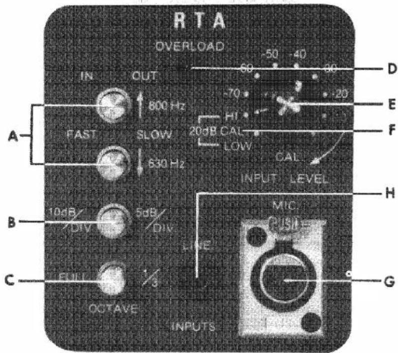
Fig. 3.3 RTA Section
RTA (See Fig. 3.3)
This segment of the unit provides jacks for the application of electrical signals to the analyzer circuitry. Furthermore, the controls and switches of the RTA segment affect the CRT display as follows:
fast/slow
The normal operating position (when displaying program signals) of these switches is IN. This setting allows viewing of the displayed signal with a minimum of averaging. Setting these switches to their OUT position selects detector time constants which provide averaging of the displayed signal such that equalization adjustments can be made with greater ease. The top switch of the two selects those frequencies from 800Hz to 20KHz, while the bottom switch selects frequencies from 16Hz to 630Hz. (Fig. 3.3A)
dB/division
When set to its IN position, the dB PER DIVISION switch selects a vertical CRT sensitivity of 10dB per division. A vertical sensitivity of 5dB per division is selected by releasing the switch to its OUT position. When calibrating the CRT graticule, it is most convenient to select the 10dB per division position.(Fig.3.3B)
full-1/3
You may choose to view the displayed signal in a full 1 octave format or a 1/3 octave format by engaging (IN) or releasing (OUT) the switch labeled FULL - 1/3. A full octave is selected by setting the switch to its IN position. When performing equalization adjustments, it is recommended to begin in the full format, using the 1/3 octave format for fine tuning. (Fig. 3.3C)
overload indicator
The red LED, indicating an overload condition, will glow whenever the amplitude of the input signal exceeds a level preset on a voltage regulator. Should the LED illuminate, a greater amount of attenuation should be selected via the INPUT LEVEL CONTROL.(Fig. 3.3D)
input level
Two portions of the INPUT LEVEL control offer selectable attenuation to all input signals. The outside control adds up to 70dB of attenuation in 10dB steps whereas the inside or vernier portion can further attenuate the signal by 40dB. (Fig.3.3E)

Fig. 3.4 Pink Noise Section
PINK NOISE
Access to the pink noise generator signal is made through either one of the front panel jacks (Fig. 3.4A,B) or the pin jack on the rear panel (Fig. 3.5). The pink noise generator is switched on by pulling the front panel output level control (Fig. 3.4C), while the intensity of the signal is controlled by rotating the same control. Also, for a 40dB reduction of signal strength (line level to mic level), the -40dB switch can be depressed. (Fig. 3.4D)
calibration
1. Purpose
A. Vertical Calibration - Vertical calibration causes the markings around the input level attenuator to be in agreement with the markings on the CRT graticule. Also, vertical calibration adjusts the gain of the vertical amplifier so that one vertical division is represented by 5dB or 10dB depending upon the position of the dB/DIV switch.
B. Horizontal calibration ensures that the numbers at the bottom of the CRT graticule will correctly identify frequency locations within the display.
II. Procedure
A. Vertical
- Set the pink noise output level control to three o'clock.
-
Adjust the vernier input level attenuator to CAL (fully clockwise).
-
Turn the stepped input level attenuator to LOW.
- With the vertical position control, position the trace at the bottom graticule line.
- Move the stepped input level attenuator to H1.
a. The trace will ascend when you move the stepped input level attenuator to HI. The vertical gain should be set so that the trace will ascend by 20dB. Twenty dB will be represented by 2 or 4 vertical divisions depending on the position of the dB/DIV switch.
Note: In the event where the trace does not ascend by the stated amount, repeat steps 3, 4 and 5.
B. Horizontal
- Set the stepped input level attenuator to either HI or LOW.
-
Set the OCTAVE switch to the one-third octave format (out).
-
Adjust the vertical position control so that the trace runs through one of the three sets of horizontal ditto marks.
- With the horizontal position control, position the trace in a manner whereby the output of the 16 Hz filter falls between the first two ditto marks.
- Using the horizontal gain control, set the right end of the trace to touch the first vertical line beyond 16KHz.

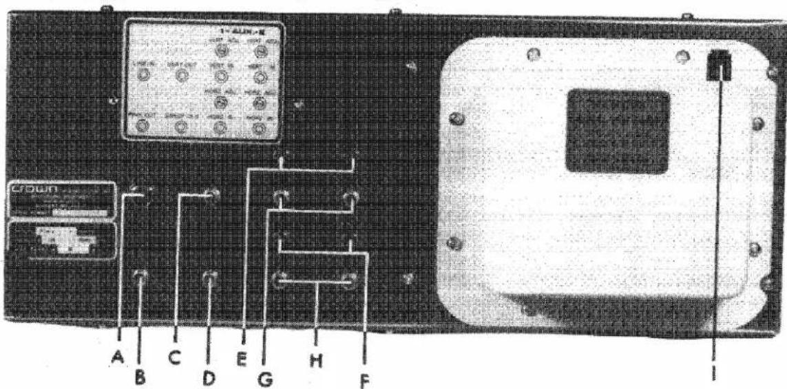
Fig. 3.5 Rear Panel
3.6 Rear Panel Controls and Connections
LINE IN
LINE LEVEL inputs accept voltages between approximately 75mv to 25v. This 14 " phone (Fig. 3.5A) jack will be overridden by the insertion of a plug into either one of the two front panel input jacks.
PINK OUT
This pin jack connector (Fig. 3.5B) along with the two front panel jacks, supplies pink noise whose intensity is controlled by the pink noise output level control.
VERT OUT
The vertical output jack (Fig. 3.5C) offers a means of connecting other instruments to the RTA-2 that require a vertical input. Example of this would include connecting the RTA-2 up to a storage scope.
SWEEP OUT
The 60Hz ramp voltage from this jack (Fig. 3.5D) can be used to drive the horizontal (X) input of an oscilloscope.
VERT ADJ-HORIZ ADJ
When viewing an x vs. y display, it may be necessary to increase the sensitivity of the vertical or horizontal input. This is done by turning the vertical or horizontal adjustment screw (Fig. 3.5E,F) with a small flat head screwdriver.
VERT & HORIZ IN
For an x vs. y display, the vertical and horizontal input jacks (Fig. 3.5G,H) are used. Two sets of these jacks are provided, and selected by a front panel control.
ASTIGMATISM
The astigmatism control, (Fig. 3.51) located at the upper right hand corner of the rear panel, is used together with the focus control to adjust the trace for optimum clarity.

natural_image
Close-up of electronic components including capacitors, resistors, and a motor (no visible text or symbols)Fig. 3.6 Pink Noise/Input Board
3.7 Phantom Power Supply
Some condenser microphones require a DC operating voltage. For this reason, a phantom power supply has been built into the RTA-2. This feature is standard on all units with serial number 20869 and above. For units below this number, a slight modification must be made. Referring to Fig. 3.6, locate the PINK NOISE & INPUT board on the underside of the RTA chassis and find jumper "A". Cut this jumper and insert a 14 watt 680 ohm resistor into the two PC board receptacles indicated by "B" of Fig. 3.6. 18 volts will now be available at the balanced input jack on the front panel.
Note: The above modification was based on an AKG451 (CK22) mic. Should any complications arise as a result of this modification, please contact the Crown Technical Services Department.
3.8 Modifying AC Mains Voltage
Fig. 3.7 shows the jumper arrangement for modifying the RTA-2 to operate on 100, 120, 200, 220, and 240 VAC.
* 100 volt operation - jumper A and D, B and E and move black wire to E.
* 120 volt operation - jumper A and D, C and F and move black wire to F.
* 200 volt operation - jumper B and D, and move black wire to E.
* 220 volt operation - jumper B and D, and move black wire to F.
* 240 volt operation - jumper C and D, and move black wire to F.
* Use 1/16A MDL fuse for 200V, 220V, 240V line.
* Use 1/8A MDL fuse for 100V, 120V line.
crown

Fig. 3.7 AC Voltages
SECTION 4 TECHNICAL ASPECTS OF UNIT
4.1 General
The RTA-2 Real Time Audio Analyzer came to be as a spin-off of the RTA-1 which, in turn, was a demonstration tool used in conjunction with the CROWN EQ-2 equalizer. Information contained in this section of the manual is by no means meant to be a troubleshooting guide, but merely a brief technical explanation of the unit for those interested.
4.2 Principles of the RTA-2
There are essentially three major sections in the makeup of the RTA-2: the pink noise generator, the oscilloscope, and the audio analyzer. Each are individual circuits within the RTA-2. The noise generator begins with a digitally derived source whose output voltage is white noise. Active filters provide the rolloff and the filtering to change the white noise into pink noise and limit the bandwidth of the signal. An unbalanced, pseudo random pink noise signal is then delivered to the unbalanced jacks while the same signal plus an inverted version is applied to the XLR connector to provide a balanced output signal. Front panel switches control the On/Off function and signal attenuation.
Input terminations to the oscilloscopic circuitry appear on the rear panel of the RTA-2. In addition to horizontal and vertical output connectors, there are two sets of auxiliary input jacks. Adjacent to these jacks are individual sensitivity controls. Signals introduced at either set of auxiliary input jacks are buffered and amplified before being applied to the deflection plates. Front panel controls serve to vary the intensity and focus of the trace; position the trace on the screen and adjust the gain of the horizontal and vertical amplifiers.
As sound is being picked up by a microphone, it is, at the same instant, being transformed into an electrical signal. Connecting this signal to the RTA-2, via an unbalanced or balanced input jack, introduces it to either one or two gain blocks (depending on the strength of the input signal). After the signal has been amplified sufficiently, it is directed to a filter bus and distributed among a group
of 32 filters. Each of the 32 filters is a bandpass filter tuned to a center frequency selected at 1/3 octave intervals across the audio band (20Hz - 20K Hz). Voltages appearing at the output of each filter are then fed to complex multiplexing circuitry which acts in conjunction with the sweep generator to direct the signals in their proper sequence to a logarithmic amplifier. Because the output of the multiplexing circuitry has some 60dB of dynamic range, the signals must be converted logarithmically so that they appear on the screen as linear (dB units).
4.3 Block Diagram Circuit Theory
A 491.5K Hz signal, generated by the master clock, is used to drive the pink noise generator and the frequency dividing network. The output of the pink noise generator is a pseudo-random pink noise signal and is used in testing and analyzing sound systems. (See Fig. 4.1) Signals of line level are introduced - via a front or rear panel jack - to the input attenuator and gain stage. In this stage, the input signal is amplified and sent on to the filters where it is broken down to 32 distinct output voltages according to frequency. A multiplexer has been incorporated along with a sweep generator to provide control voltages that will arrange the analyzed information on the CRT in proper sequence. A logarithmic amplifier is used to convert the multiplexer output signal before it is sent on to the deflection amplifiers. This is done so that the displayed information will appear linear. Vertical and horizontal deflection amplifiers boost the signal to a level of sufficient value for use by the deflection plates. A low voltage power supply provides +200 volts in addition to a positive and negative 15 volts while a high voltage supply utilizes a voltage multiplier circuit to furnish -1800 volts to the CRT. Whenever the RTA-2 is in an auxiliary mode and no input signal is being applied, the beam gate circuitry reduces the intensity of the trace to prevent CRT phosphor burns.

flowchart
graph TD
    A["MASTER CLOCK 491.5 KHZ"] --> B["20 STAGE PSEUDO RANDOM BINARY GENERATOR"]
    B --> C["VAR OUT"]
    C --> D["3 dB/OCTV. PINK FILTER"]
    D --> E["40 KHz 1 dB CHEBY. LP FILTER"]
    E --> F["10 Hz 1 dB CHEBY. HP FILTER"]
    F --> G["40 dB ATTEN. SW."]
    G --> H["BALANCED PINK NOISE OUT"]

    I["○"] --> J["BALANCED INPUT MIC AMP"]
    J --> K["LINE IN"]
    K --> L["40 dB INPUT ATTEN."]
    L --> M["+1"]
    M --> N["0-20 dB AMF"]
    N --> O["VAR GAIN"]
    O --> P["3.5-13.5 dB"]
    P --> Q["BANDPASS FILTER NO.1"]
    Q --> R["AC - DC CONV. NO. 1"]
    R --> S["SPEED SW. LP FILTER NO. 1"]
    S --> T["1/3 - 1 OCTV. SW NO.1"]
    T --> U["32 INPUT MPX 1 OUT"]
    U --> V["TO LOG AMP"]

    W["LOW VOLTAGE POWER SUPPLY"] --> X["+200"]
    X --> Y["OVERLOAD INDICATOR"]
    Y --> Z["±15"]

    AA["FROM MPX"] --> AB["LOG AMP"]
    AB --> AC["AMP & BASELINE CLIPPER"]
    AC --> AD["RTA"]
    AD --> AE["VERT. GAIN"]
    AE --> AF["VERT. POS"]
    AF --> AG["VERT DEF. AMP"]
    AG --> AH["CRT"]
    AH --> AI["HOR DEFL."]
    AI --> AJ["HOR GAIN"]
    AJ --> AK["60 Hz RAMP GENERATOR"]
    AK --> AL["SWEEP OUT"]
    AL --> AM["26 dB"]

    AN["AUX 1 VERT."] --> AO["26 dB"]
    AP["AUX 2 VERT."] --> AQ["26 dB"]

    AR["AVL D"] --> AS["OVL D"]

    AT["AVL D"] --> AU["OVL D"]

    AV["AVL D"] --> AW["OVL D"]

    AX["AVL D"] --> AY["OVL D"]

    AZ["AVL D"] --> BA["OVL D"]

    BB["AVL D"] --> BC["OVL D"]

    BD["AVL D"] --> BE["OVL D"]

    BF["AVL D"] --> BG["OVL D"]

    BH["AVL D"] --> BI["OVL D"]

    BJ["AVL D"] --> BK["OVL D"]

    BL["AVL D"] --> BM["OVL D"]

    BN["AVL D"] --> BO["OVL D"]

    BP["AVL D"] --> BQ["OVL D"]

    BQ --> BR["AVL D"]

    BS["AVL D"] --> BT["OVL D"]

    BU["AVL D"] --> BV["OVL D"]

    BW["AVL D"] --> BX["OVL D"]

    BY["AVL D"] --> BZ["OVL D"]

    CA["AVL D"] --> CB["OVL D"]

    CC["AVL D"] --> CD["OVL D"]

    CE["AVL D"] --> CF["OVL D"]

    CG["AVL D"] --> CH["OVL D"]

    CI["AVL D"] --> CJ["OVL D"]

    CK["AVL D"] --> CL["OVL D"]

    CM["AVL D"] --> CN["OVL D"]

    CO["AVL D"] --> CP["OVL D"]

    CEI["AVL D"] --> CEII["OVL D"]

    CEJ["AVL D"] --> CEK["OVL D"]

    CEK --> CELI["OVL D"]

    CELE["AVL D"] --> CEM["OVL D"]

    CEM --> CEMQ["OVL D"]

    CEMQ --> CEMQ1["OVL D"]

    CEMQ1 --> CEMQ2["OVL D"]

    CEMQ2 --> CEMQ3["OVL D"]

    CEMQ3 --> CEMQ4["OVL D"]

    CEMQ4 --> CEMQ5["OVL D"]

    CEMQ5 --> CEMQ6["OVL D"]

    CEMQ6 --> CEMQ7["OVL D"]

    CEMQ7 --> CEMQ8["OVL D"]

    CEMQ8 --> CEMQ9["OVL D"]

    CEMQ9 --> CEMQ10["OVL D"]

    CEMQ10 --> CEMQ11["OVL D"]

    CEMQ11 --> CEMQ12["OVL D"]

    CEMQ12 --> CEMQ13["OVL D"]

    CEMQ13 --> CEMQ14["OVL D"]

    CEMQ14 --> CEMQ15["OVL D"]

    CEMQ15 --> CEMQ16["OVL D"]

    CEMQ16 --> CEMQ17["OVL D"]

    CEMQ17 --> CEMQ18["OVL D"]

    CEMQ18 --> CEMQ19["OVL D"]

    CEMQ19 --> CEMQ20["OVL D"]

    CEMQ20 --> CEMQ21["OVL D"]

    CEMQ21 --> CEMQ22["OVL D"]

    CEMQ22 --> CEMQ23["OVL D"]

    CEMQ23 --> CEMQ24["OVL D"]

    CEMQ24 --> CEMQ25["OVL D"]

    CEMQ25 --> CEMQ26["OVL D"]

    CEMQ26 --> CEMQ27["OVL D"]

    CEMQ27 --> CEMQ28["OVL D"]

    CEMQ28 --> CEMQ29["OVL D"]

    CEMQ29 --> CEMQ30["OVL D"]

    CEMQ30 --> CEMQ31["OVL D"]

    CEMQ31 --> CEMQ32["OVL D"]

    CEMQ32 --> CEMQ33["OVL D"]

    CEMQ33 --> CEMQ34["OVL D"]

    CEMQ34 --> CEMQ35["OVL D"]

    CEMQ35 --> CEMQ36["OVL D"]

    CEMQ36 --> CEMQ37["OVL D"]

    CEMQ37 --> CEMQ38["OVL D"]

    CEMQ38 --> CEMQ39["OVL D"]

    CEMQ39 --> CEMQ40["OVL D"]

    CEMQ40 --> CEMQ41["OVL D"]

    CEMQ41 --> CEMQ42["OVL D"]

    CEMQ42 --> CEMQ43["OVL D"]

    CEMQ43 --> CEMQ44["OVL D"]

    CEMQ44 --> CEMQ45["OVL D"]

    CEMQ45 --> CEMQ46["OVL D"]

    CEMQ46 --> CEMQ47["OVL D"]

    CEMQ47 --> CEMQ48["OVL D"]

    CEMQ48 --> CEMQ49["OVL D"]

    CEMQ49 --> CEMQ50["OVL D"]

    CEMQ50 --> CEMQ51["OVL D"]

    CEMQ51 --> CEMQ52["OVL D"]

    CEMQ52 --> CEMQ53["OVL D"]

    CEMQ53 --> CEMQ54["OVL D"]

    CEMQ54 --> CEMQ55["OVL D"]

    CEMQ55 --> CEMQ56["OVL D"]

    CEMQ56 --> CEMQ57["OVL D"]

    CEMQ57 --> CEMQ58["OVL D"]

    CEMQ58 --> CEMQ59["OVL D"]

    CEMQ59 --> CEMQ60["OVL D"]

    CEMQ60 --> CEMQ61["OVL D"]

    CEMQ61 --> CEMQ62["OVL D"]

    CEMQ62 --> CEMQ63["OVL D"]

    CEMQ63 --> CEMQ64["OVL D"]

    CEMQ64 --> CEMQ65["OVL D"]

    CEMQ65 --> CEMQ66["OVL D"]

    CEMQ66 --> CEMQ67["OVL D"]

    CEMQ67 --> CEMQ68["OVL D"]

    CEMQ68 --> CEMQ69["OVL D"]

    CEMQ69 --> CEMQ70["OVL D"]

    CEMQ70 --> CEMQ71["OVL D"]

    CEMQ71 --> CEMQ72["OVL D"]

    CEMQ72 --> CEMQ73["OVL D"]

    CEMQ73 --> CEMQ74["OVL D"]

    CEMQ74 --> CEMQ75["OVL D"]

    CEMQ75 --> CEMQ76["OVL D"]

    CEMQ76 --> CEMQ77["OVL D"]

    CEMQ77 --> CEMQ78["OVL D"]

    CEMQ78 --> CEMQ79["OVL D"]

    CEMQ79 --> CEMQ80["OVL D"]

    CEMQ80 --> CEMQ81["OVL D"]

    CEMQ81 --> CEMQ82["OVL D"]

    CEMQ82 --> CEMQ83["OVL D"]

    CEMQ83 --> CEMQ84["OVL D"]

    CEMQ84 --> CEMQ85["OVL D"]

    CEMM["VOLTAGE POWER SUPPLY"] --> AD
Fig. 4.1 Block Diagram
4.4 Detailed Circuit Theory
Balanced microphone signals entering the RTA-2 through J1 are fed to the gates of FETs C-100A and C-100B. The mic gain is adjusted with C-R135. Both sides of the balanced signal meet at buffer C-IC105D, whose non-inverting input is the arm of the common-mode-rejection trimmer pot C-R143. The now unbalanced output of C-IC105D appears at pin 14 and is applied to the next stage of amplification.
Line input jacks J2 and J3 are both pin jacks; J2 is a front panel jack, J3 a rear panel jack. Because J2 and J3 are connected in series, plugging into the front panel jack will disconnect source devices connected to the rear panel jack.
Signals injected via the line input jacks, J2 and J3, are fed through blocking capacitor C-C126 and buffer C-IC106A to the input attenuator C-SW100A. C-IC106D changes the impedance to a low value before sending the signal on to the front panel input attenuator C-R155. C-R156 together with C-IC105C and a resistor pack make up an attenuation network which provides the proper level of attenuation as per the markings on the RTA-2 front panel. Finally, the output of C-IC105C delivers the signal to the next stage which is the filter bank.
Each of the 32 filters if fed from the filter input buss (J1P7), through buffer F-IC100A. The actual filter is made up of components F-R100, F-C100, F-R101, F-R102, F-C101, F-R103, and F-IC100B. F-R102 tunes the frequency of teh filter. F-C102 couples the AC signal through filter gain control F-R104 to the precision rectifier consisting of F-IC100C and diodes F-D101, and F-D102. At the output of the DC amplifier F-IC100D, a rectified and amplified version of the filter output appears and is stored on F-C106.
When a slower response time is desired, the front panel buttons labeled fast and slow may be released. Electrically this action turns FET 100 on which inserts capacitor F-C105 in parallel with F-C106 thus adding their values and slowing the integration time of the RC network. F-IC101A dn F-IC101B are CMOS switches. When the control gates of these switches are grounded by depressing the front panel octave switch, sets of three filters combine and deliver an average voltage to the input of its associated multiplexer.
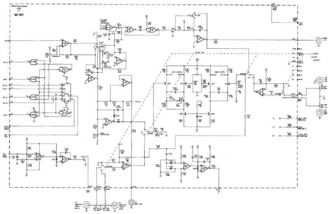
In order to get the information from the filters into the correct location on the CRT, multiplexing circuitry has been provided. The heart of the multiplexing circuitry is D-IC105 which is a dividing network. The same clock signal that is used by the pink noise generator is also used to drive D-IC105. Outputs of the counter are square wave pulse trains whose frequencies are divisions of the clock frequency (491.5KHz). As D-IC105 counts, it is essentially allowing the signals from the 32 filters to pass in sequence through F-IC132, F-IC133, F-IC134, and F-IC135 to the logarithmic amplifier.
The output signal from the multiplexer has over 60dB of possible dynamic range. Therefore, it is necessary to distribute the information across the CRT so that each filter's output will be discernable. The circuitry which improves the display dynamics of the filter output information is the logarithmic amplifier and consists of the semiconductors labeled D-Q108, D-IC102A, D-IC102B and D-IC102C. Also, surrounding components adjust linearity (D-R100), offset (D-R116) and gain (D-R108) respectively. Moving to D-IC102D, a precision limiter (base-line clamp), the signal is amplified and applied to the vertical deflection circuitry through SW100B.
Backing up a little, let's look at D-1C103C. Whenever it is desired to have the information being displayed on the RTA's screen also displayed on a second oscilloscopic instrument, the rear panel vertical output jack, (J7), is used. The vertical output signal is derived from the logarithmic amplifier, buffered by D-1C103C and applied to the vertical output jacks.
Signals injected through the horizontal and vertical input jacks are amplified and buffered by a section of D-IC103 (A or D) and applied through portions of SW100 to the vertical and horizontal deflection circuitry. D-R148 controls the vertical position of the trace, D-R149 controls the horizontal position and SW26 selects a vertical sensitivity of 5dB per division or 10dB per division. These adjustments all appear on the front panel.
D-IC104B and D-IC104C along with their associated componentry, make up a detector circuit whose function is to reduce the trace intensity during the absence of a vertical input signal. The reason for this circuitry is to eliminate the possibilities of burning holes in the CRT's phosphor coating.
D-IC104A and D-IC104D form a voltage comparator circuit. This circuit is set up so that anytime a voltage enters the RTA-2 that is greater than the voltage set at the input of the comparator, D-Q107 will be biased into operation thereby illuminating the front panel overload indicator LED-2. The low voltage power supplies provide the proper operating voltages to the RTA-2 circuitry and light the power-on indicator. The low voltage power supply furnishes plus and minus 15 volts as well as plus 200 volts while the high voltage supply uses several capacitors and diodes in a voltage multiplier configuration to supply -1800 volts to the anodes of the CRT.
ENERAL
CIRCUITS SHOWN START WITH SN20558
ALL COMPONENTS MOUNTED OFF BOARDS ARE NUM-
BERED 1-9 PER BOARD
ALL COMPONENTS ARE NUMBERED 100-199 PER BOARD
EACH BOARD HAS A CODE LETTER. THEY ARE LISTED
BELC
- LOW VOLTAGE POWER SUPPLY BOARD #9770
3 - ULTRA HIGH VOLTAGE
C - INPUT BOARD #9780
0 - DEFLECTION BOARD #6788
- LOW FILTER BOARD =6786
- HI FILTER BOARD 4678
ALL RESISTORS ARE IN OHME, CAPACITOR
FARADS UNLESS OTHERWISE DESIGNATED
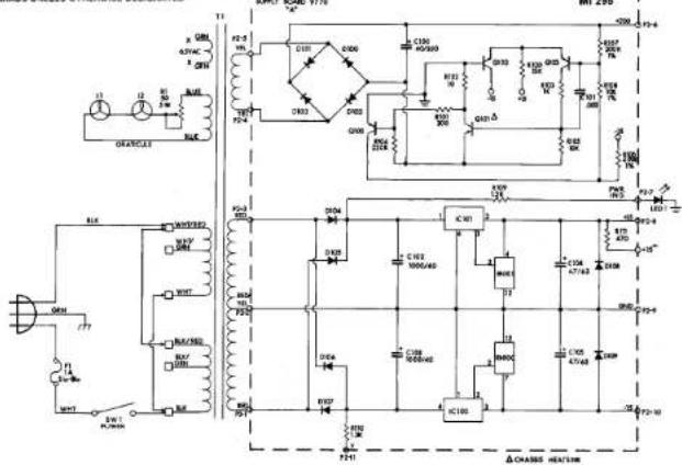
POWER SUPPLY
- CIRCUIT SHOWN WIRED FOR 120 YAC
- EWI SHOWN IN OFF POSITION
- EN DENOTES REGISTOR NETWORK
- AN DELETES RESISTOR NETWORK A DEMOTER CHASSIC HEATRINKED
- Y DENOTES CATHODE LEAD TO LED 2. OVLD INDICATOR
Fig. 4.2 RTA-2 Schematics Diagrams

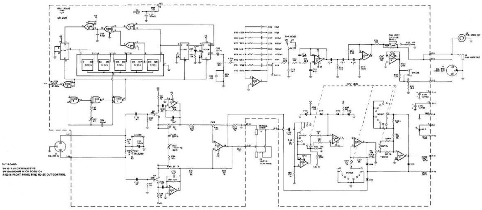


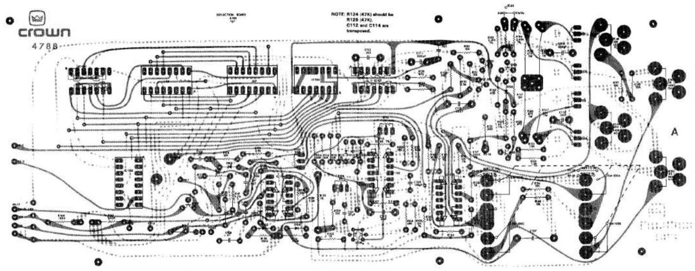
DEFLECTION BOARD
- J1-P CONNECTIONS GO TO THEIR RESPECTIVE CON
- SCORE SW100 SHOWN IN RTA POSITION


SECTION 5 PARTS LIST
5.1 General Information
This section contains parts lists for the RTA-2 real time analyzer. The information in this section will aid the service technician in rapidly and accurately identifying and replacing defective parts.
Reference designations correspond to those shown in the schematic diagrams in Sec. 4.
5.2 Standard and Special Parts
Many electrical and electronic parts and many attaching type parts used in the RTA-2 are standard items stocked by and available from electronic supply houses. However, some electronic parts that appear to be standard are actually special. This means that Crown has selected the item to meet specific requirements. A part ordered by the Crown part number will assure an acceptable replacement. Structural items such as covers and panels are available only from Crown.
5.3 Ordering Parts
When ordering parts for the RTA-2, be sure to give the model and serial number and include the part description and Crown part number from the parts list.
Note: All component designation numbers are preceded by board code letter -
| Schematic Designation | Description | Qty. | Crown Part No. | Other Information |
| RTA-2 High Low Voltage Module | 41989 | |||
| Resistors | ||||
| A-R100 | 15K ohm 1⁄2W 5% CF | 1 | 1064 | |
| A-R101 | 300 ohm 1⁄4W 5% CF | 1 | 3801 | |
| A-R102 | 10 ohm 1⁄4W 5% CF | 1 | 3753 | |
| A-R103 | 1K ohm 1⁄4W 5% CF | 1 | 2627 | |
| A-R104 | 220K ohm 1⁄4W 5% CF | 1 | 4219 | |
| A-R105 | 10K ohm 1⁄4W 5% CF | 1 | 2631 | |
| A-R106 | 4.99K ohm 1⁄4W 1% MF | 1 | 3686 | |
| A-R107 | 200K ohm 1⁄2W 5% MF | 1 | 3197 | |
| A-R108 | 10K ohm 1⁄2W 1% MF | 1 | 2343 | |
| A-R109, R110 | 1.3K ohm 1⁄2W 1% MF | 2 | 3114 | |
| A-R111 | 470 ohm 1⁄4W 5% CF | 1 | 2626 | |
| A-RN100, RN101 | Resistor trim network | 2 | 4445 | |
| Capacitors | ||||
| A-C100 | 40mF 450V | 1 | 4848 | |
| A-C101 | .001mF Cer Disc | 1 | 2288 | |
| A-C102, C103 | ||||
| C106, C107 | 1000mF 40V | 4 | 4303 | |
| A-C104, C105 | 4.7mF 63V | 2 | 4253 | |
| Diodes | ||||
| A-D100, D101, D102, D103, D104, D105, D106, D107 | 1N4004 | 8 | 2851 | |
| Integrated Circuits | ||||
| A-IC100 | 79MGT2C | 1 | C 5486-3 -Reg | |
| A-IC101 | 78MGT2C | 1 | C 4296-7 +Reg | |
| Transistors | C 5487-1 | |||
| A-Q100, Q102 | PN4250A PNP | 2 | 3786 | |
| A-Q101 | NDS128 NPN | 1 | C 4061-5 | |
| A-Q103 | MPSA93 PNP | 1 | 3578 | |
| Miscellaneous | ||||
| Power supply heat sink | 1 | 9756 | ||
| A | Power Supply Board | 1 | 9770 | *Not available for purchase |
| Int star lockwasher #4 | 4 | 1824 | ||
| 4-4OX .25 RHS screw | 4 | 1827 | ||
| 4-40 hex nut | 4 | 1938 | ||
| 7 cable tie | 3 | 1812 | ||
| 312 X 125 X 031 nylon washer | 4 | 4567 |
crown
| Schematic Designation | Description | Qty. | Crown Part No. | Other Information |
| Ultra High Voltage Module | 41988 | |||
| Resistors | ||||
| B-R100, R103 | 47K ohm 1W 5% Comp | 2 | 4866 | |
| B-R101, R102 | 10K ohm 1⁄4W 5% CF | 2 | 2631 | |
| B-R104 | 51K ohm 1⁄4W 5% | 1 | 2881 | |
| B-R105 | 5M ohm POT | 1 | 4779 | Focus control |
| B-R106, R107 | 7.5M ohm 1W 5% Comp | 2 | 4874 | 7323-6 |
| B-R108 | 1M ohm 1⁄4W 5% | 1 | 3198 | |
| B-R109 | 3.3M ohm 1⁄4W 5% CF | 1 | 4237 | |
| B-R110 | 250K POT | 1 | 4778 | Astig control |
| Capacitors | ||||
| B-C100, C101 | .001mF Cer Disc | 2 | 2288 | |
| B-C102, C103, C104, C105, C106, C107, C108, C109, C110, C111 | .02mF 500V Cer Disc | 10 | 4847 | |
| B-C112, C117 | .0047mF 3kV Cer Disc | 2 | 4845 | |
| B-C113, C114 | .01mF 1kV Cer Disc | 2 | 4846 | |
| B-C115, C118 | .1mF 200V Filmatic | 1 | 2938 | |
| B-C116 | 4.7mF 63V Vertical | 1 | 4253 | |
| Diodes | ||||
| B-D100, D101 | 1N4148 | 2 | 3181 | |
| B-D102, D103, D104, D105, D106, D107, D108, D109, D110, D111, D112, D113, D114, D115 | 1N4005 | 15 | 4842 | |
| Integrated Circuits | ||||
| B-IC-1 | 4060 Hex inverter | 1 | 4665 | |
| Transistors | ||||
| B-Q100, Q101, Q102, Q103 | NDS128 NPN | 4 | 4061 | |
| Miscellaneous | ||||
| B | RTA ultra hi voltage brd. | 1 | 9772 | *Not available for purchase |
| 14 Pin DIL IC socket | 1 | 3450 | ||
| RTA-2 Input Module | 41987 | |||
| Resistors | ||||
| C-R100, R130, R-137 | 1M ohm 1⁄4W 5% CF | 3 | 3198 | |
| C-R101 | 3.9K ohm 1⁄4W 5% CF | 1 | 2630 | |
| C-R102 | 2K ohm heli-pot trim | 1 | 3672 | Noise |
| C-R103 | 25K ohm audio | 1 | 4770 | Pink noise level |
| C-R104 | 150 ohm 1⁄4W 5% CF | 1 | 3799 | |
| C-R105 | 4.22K ohm 1⁄2W 1% MF | 1 | 4854 | |
| C-R106 | 8.45K ohm 1⁄2W 1% MF | 1 | 4857 | |
| C-R107 | 16.9K ohm 1⁄2W 1% MF | 1 | 4860 | |
| C-R108 | 34K ohm 1⁄2W 1% MF | 1 | 4864 | |
| C-R109 | 68.1K ohm 1⁄2W 1% MF | 1 | 4916 | |
| C-R110 | 137K ohm 1⁄2W 1% MF | 1 | 4869 | |
| C-R111 | 274K ohm 1⁄2W 1% MF | 1 | 4871 | |
| C-R112 | 330K ohm 1⁄4W 5% CF | 1 | 4222 | |
| C-R113, R115 | 4.2K ohm 1⁄4W 5% CF | 2 | 4855 | |
| C-R114 | 36K ohm 1⁄4W 5% CF | 1 | 4865 | |
| C-R116 | 12K ohm 1⁄4W 5% CF | 1 | 2878 | |
| C-R117 | 160K ohm 1⁄4W 5% CF | 1 | 4217 | |
| C-R118 | 3.3K ohm 1⁄4W 5% CF | 1 | 2629 | |
| C-R119, R124 | 300 ohm 1⁄4W 5% CF | 2 | 3801 | |
| C-R120, R123, R148, R149 | 10K ohm 1⁄4W 5% CF | 4 | 2631 | |
| C-R121, R125 | 2.21K ohm 1⁄2W 1% MF | 2 | 4906 | |
| C-R122, R126 | 25.5 ohm 1⁄2W 1% MF | 2 | 4905 | |
| C-R127 | Selected | 1 | ||
| C-R128, R129 | 1K ohm 1⁄2W 1% MF | 2 | 3194 | |
| C-R131 | 20K ohm 1⁄2W 1% MF | 1 | 3752 | |
| C-R132, R-134 | 10M ohm 1⁄4W 10% Comp | 2 | 3221 | |
| C-R135 | 5K ohm Helipot trim | 1 | 3670 | CCW log |
| C-R136 | 180 ohm 1⁄4W 5% CF | 1 | 2873 | |
| C-R139, R140 | 2K ohm 1⁄4W 1% MF | 2 | 4505 | |
| C-R141, R147, R133 | 10K ohm 1⁄4W 1% MF | 3 | 4859 | |
| C-R142, R144 | 9.9K ohm 1⁄4W 1% MF | 2 | 4858 | |
| C-R143 | 200 ohm Helipot trim | 1 | 3683 | |
| C-R145, R150 | 1K ohm 1⁄2W 1% MF | 2 | 4850 | |
| C-R146, | 1M ohm 1⁄2W 1% MF | 1 | 4872 | |
| C-R152, R138 | 20K 1⁄4W 1% MF | 2 | 4861 | |
| C-R153 | 200K ohm 1⁄4W 5% CF | 1 | 3622 | |
| C-R154 | 1.1K ohm 1⁄4W 1% MF | 1 | 4851 | |
| C-R155 | 25K ohm Audio | 1 | 4779 | |
| C-R156 | 13K ohm 1⁄4W 5% CF | 1 | 4300 | |
| C-RN100 | Resistor network | 1 | 4280 | |
| C-R157 | 100 ohm 1⁄4W 5% CF | 1 | 2872 | |
| C-R151 | 2K 1⁄4W 5% CF | 1 | 3804 | |
| Capacitors | ||||
| C-C100 | .1mF 12V Cer Disc | 1 | 2600 | |
| C-C101 | 470pF Mica | 1 | 2511 | |
| C-C102 | 33mF 50V | 1 | 3679 | |
| C-C103 | .015mF 200V Filmatic | 1 | 3288 | |
| C-C104 | 200pF Mica | 1 | 3411 | |
| C-C105, C106 | 917pF 63V 2.5 Styr | 2 | 4287 | |
| C-C107 | 1830pF 63V 2.5 Styr | 1 | 4286 | |
| C-C108 | 3660pF 63V 2.5 Styr | 1 | 4285 | |
| C-C109 | 7330pF 63V 2.5 Styr | 1 | 4284 | |
| C-C110 | 14,700pF 63V 2.5 Styr | 1 | 4283 | |
| C-C111 | .0293mF 200V 2.5 | 1 | 4293 | |
| C-C112 | .058mF 100V 2.5 | 1 | 4292 | |
| C-C113 | .001mF 200V Filmatic | 1 | 3480 | |
| C-C114 | .0012mF | 1 | 2406 | |
| C-C115 | 47pF Mica | 1 | 3409 | |
| C-C116, C117, C118 | 1.0mF 100V 5 polycrb | 3 | 4472 | |
| C-C119, C123 | .47mF 100V 5 Polycrb | 2 | 4119 | |
| C-C120, C124 | .22mF 100V 5 Polycrb | 2 | 4510 | |
| C-C121, C125 | 10pF Mica | 2 | 2821 | |
| C-C122 | 220mF 16V Vertical | 1 | 3796 | |
| C-C126 | .047mF 250V 5 Polycrb | 1 | 4404 | |
| C-C127 | 400mF 16V Vertical | 1 | 3729 | |
| C-C128, C129, C130 | 4.7mF 63V Vertical | 3 | 4253 | |
| Diodes | ||||
| C-D100, D103 | 1N961B 10V Zener | 2 | 3549 | |
| C-D101, D102, D104, D105, D106 | 1N4148 | 5 | 3181 | |
| Integrated Circuits | ||||
| C-IC100 | MC14070 | 1 | 4833 | |
| C-IC101, C103 | MC14013 Flip Flop | 2 | 4831 | |
| C-IC102 | 4011 Quad Two Input Nand | 1 | 4529 | |
| C-IC104, IC105, IC106 | TL074 | 3 | 4696 | |
| C-IC107 | MC14006 Div-By-N-Ctr | 1 | 4832 | |
| Transistors | ||||
| C-FET100 | E4111 Dual N-Ch JFET | 1 | 4015 | |
| Miscellaneous | ||||
| C | RTA Input Board | 1 | 9780 | *Not available for purchase |
| SW100 | DPDT DB SW W/O Brckt | 1 | 4923 | |
| Xistor Lead PC Recpt | 2 | 3519 | ||
| 14 Pin D/C IC Socket | 8 | 3450 | ||
| Deflection Module | 41986 | |||
| Resistors | ||||
| D-R100 | 100K ohm Cermet Trim | 1 | 4843 | |
| D-R101, R135, R136, R140, R165, R166, R167 | 100K ohm 1⁄4W 5% CF | 7 | 2883 | |
| D-R102 | 100 ohm 1⁄4W 5% CF | 1 | 2872 | |
| D-R103, R112, R118, R161 | 10K ohm 1⁄4W 1% MF | 4 | 4859 | |
| D-R104 | 68K ohm 1⁄4W 5% CF | 1 | 3620 | |
| D-R105 | 10 ohm 1⁄4W 5% CF | 1 | 3753 | |
| D-R106 | 150K ohm 1⁄4W 1% MF | 1 | 4870 | |
| D-R107 | 2.2K ohm 1⁄4W 2% MF | 1 | 3152 | |
| D-R108 | 2K ohm Helipot Trim | 1 | 3672 | |
| D-R109, R131 | 15K ohm 1⁄4W 5% CF | 2 | 2632 | |
| D-R110 | 1K ohm 3W Q-81 | 1 | 4876 | |
| D-R111 | 4.99K ohm 1⁄4W 1% MF | 1 | 3686 | |
| D-R113 | 3K ohm 1⁄4W 1% MF | 1 | 4853 | |
| D-R114 | 36K ohm 1⁄4W 5% CF | 1 | 4865 | |
| D-R115 | 22.6K ohm 1⁄4W 1% MF | 1 | 4146 | |
| D-R116 | 5K ohm Helipot Trim | 1 | 3670 | |
| D-R117, R162 | 30.1K ohm 1⁄4W 1% MF | 2 | 4862 | |
| D-R119, R163 | 510 ohm 1⁄4W 5% CF | 2 | 4849 | |
| D-R120, R164 | 1K ohm 1⁄4W 5% CF | 2 | 2627 | |
| D-R121, R133 | 560 ohm 1⁄4W 5% CF | 2 | 2874 | |
| D-R122 | 3M ohm 1⁄4W 5% CF | 1 | 4489 | |
| D-R123, R128, D-129 | 47K ohm 1⁄4W 5% CF | 3 | 2880 | |
| D-R124 | 18K ohm 1⁄4W 5% CF | 1 | 2633 | |
| D-R125 | 3.9K ohm 1⁄4W 5% CF | 1 | 2630 | |
| D-R126 | 2.4M ohm 1⁄4W 5% CF | 1 | 4600 | |
| D-R127, R130, R134, R168, R151 | 10K ohm 1⁄4W 5% CF | 5 | 2631 | |
| D-R132 | 5.1M ohm 1⁄2W 1% MF | 1 | 5035 | |
| D-R137, R138 | 10M ohm 1⁄4W 10% Comp | 2 | 3221 | |
| D-R139 | 5.1M ohm 1⁄4W 5% CF | 1 | 4126 | |
| D-R141 | 4.7K ohm 1⁄4W 5% CF | 1 | 3939 | |
| D-R142, R150 | 5K ohm Vrt+Hrz RTA | 2 | 4773 | |
| D-R143, R157 | 12K ohm 1⁄4W 5% CF | 2 | 2878 | |
| D-R144, R145, R146, R147 | 47K ohm 1W 5% Comp | 4 | 4866 | |
crown
| Schematic Designation | Description | Qty. | Crown Part No. | Other Information |
| D-R148 | 25K ohm Vert Pos RTA | 1 | 4774 | |
| D-R149 | 25K ohm Horz Pos RTA | 1 | 4775 | |
| D-R152, R153 | 1.8K ohm 1⁄4W 5% CF | 2 | 3807 | |
| D-R154 | 4.87K ohm 1% MF | 1 | 4856 | |
| D-R155, R156 | 2.49K ohm 1⁄4W 1% | 2 | 4852 | |
| D-R158, R160 | 470 ohm 1⁄4W 5% CF | 2 | 2626 | |
| D-R159 | 2K ohm 1⁄4W 1% MF | 1 | 4505 | |
| Capacitors | ||||
| D-C100 | 100pf Mica | 1 | 3410 | |
| D-C101, C102 | 27pf Mica | 2 | 2342 | |
| D-C103 | 470pf Mica | 1 | 2511 | |
| D-C104 | .01mF Cer Disc | 1 | 1751 | |
| D-C105 | .047mF 250V 5 Polycarb | 1 | 4404 | |
| D-C106, C108 | .47MFD 100V 5 Polycrb | 2 | 4119 | |
| D-C107 | .1MFD 200 V Filmatic | 1 | 2938 | |
| D-C109 | .544pF 63V 25 Styr | 1 | 4463 | |
| D-C110, C112 | .001MFD Cer Disc | 2 | 2288 | |
| D-C111 | 200pF Mica | 1 | 3411 | |
| D-C113 | .0047mF 200V 5 Poly | 1 | 3996 | |
| D-C114 | .001mF 200V Filmatic | 1 | 3480 | |
| Diodes | ||||
| D-D100, D101, D102, D103 D104, D105, D106 | 1N4148 | 7 | 3181 | |
| Integrated Circuits | ||||
| D-IC100 | 4011 Quad 2 Input Nand | 1 | 4529 | |
| D-IC101 | 4001 Quad 2 Input Nor | 1 | 4528 | |
| D-IC102, IC103 | TE074 | 2 | 4696 | |
| D-IC104 | LM339N Volt Comparatr | 1 | 4345 | |
| D-IC105 | 4020 Shift Register | 1 | 4829 | |
| D-IC106 | 4078 8 Input Nor Gate | 1 | 4830 | |
| Transistors | ||||
| D-Q100, Q107 | PN4250A PNP | 2 | 3786 | |
| D-Q101, Q102, Q103, Q104 | ND 128 NPN | 4 | 4061 | |
| D-Q105, Q106 | Sel 2N3859A NPN | 2 | 2961 | |
| D-FET 100 | 2N5459 N-Ch JFET | 1 | 3053 | |
| D-Q108 | Sel 1T129 NPN | 1 | 4838 | |
| Miscellaneous | ||||
| D | RTA-2 Deflection Board | 1 | 4788 | *Not available for purchase |
| 14 Pin Dil IC Socket | 6 | 3450 | ||
| 16 Pin Dil IC Socket | 3 | 4508 | ||
| PC Mount Post Mod 1 | 2 | 4729 | ||
| 1P 3 Pos Scope 1NP SW | 1 | 4772 | ||
| General Miscellaneous | ||||
| Back Panel Assembly | ||||
| J2 | N112A 2 Could. HI-D Jack | 1 | 3631 | Line in |
| J4 | 350 1FP Panel Pin Jack | 1 | 1533 | Pinkout |
| J7 | 350 1FP Panel Pin Jack | 1 | 1533 | Vert out |
| J8 | 350 1FP Panel Pin Jack | 1 | 1533 | Sweep out |
| J9 | 350 1FP Panel Pin Jack | 1 | 1533 | Aux 1 Vert In |
| J10 | 350 1FP Panel Pin Jack | 1 | 1533 | Aux 1 Horz In |
| J11 | 350 1FP Panel Pin Jack | 1 | 1533 | Aux 2 Vert In |
| J12 | 350 1FP Panel Pin Jack | 1 | 1533 | Aux 2 Horz In |
| R9 | 33K ohm Pot VA2632 | 1 | 3307 | Aux 1 Vert Adj |
| R7 | 33K ohm Pot VA2632 | 1 | 3307 | Aux 1 Horz Adj |
| R8 | 33K ohm Pot VA2632 | 1 | 3307 | Aux 2 Vert Adj |
| R6 | 33K ohm VA2632 | 1 | 3307 | Aux 2 Horz Adj |
| CRT 14 Pin Socket | 1 | 4839 | ||
| 3823-1 Fuse Block | 1 | 3776 | ||
| E1 | 3A6 1A Slow Blow | 1 | 4875 | |
| T1 | 11939 RTA XFMR | 1 | 4762 | |
| CRT 1 | 5 DEP-31F CRT | 1 | 4757 | |
| Front Panel Assembly | ||||
| J1j | XLR3-32 Panel M Cannon | 1 | 1525 | Pink noise, Balanced out |
| J6 | XLR3-31 Panel F Cannon | 1 | 4902 | Mic Input |
| J3, J5 | N112A 2 Cond. Hi-D Jack | 2 | 3631 | Mic line inputPink noise output |
| R5 | 250K ohm Astig | 1 | 4778 | Astigmatism control |
| R2 | 25K ohm Audio HKX450 | 1 | 4771 | Intensity control |
| R1 | 50 ohm AW45 | 1 | 4776 | Illum control |
| SW1 | 1 Pos Rotary Prw Sw | 1 | 3492 | Power on/off |
| Led 1 | Amber LED MV5153 | 1 | 4342 | Power on light |
| LED 2 | Red LED MV5053 | 1 | 4341 | Overload indicator |
| SW2 a,b,c,d | 4 St-Pushbutton Sw | 1 | 4765 | a) Octaveb) 10dB/SDBC) Hi Fast/Slowd) Lo Fast/Slow |
| Q1 | MPSA43 | 1 | 3810 | |
crown
| Schematic Designation | Description | Crown Qty. Part No. | Other Information | |
| Low Filter #1 | ||||
| Resistors | ||||
| E-RN162 | Resistor Network | 1 | 4713 | |
| E-RN163 | Resistor Network | 1 | 4712 | |
| E-R389 | 1K ohm Helipot Trim | 1 | 3669 | Frequency Adjust |
| E-R390 | 5K ohm Helipot Trim | 1 | 3670 | Filter Gain Adjust |
| E-R391, R392 | 1M ohm 1⁄4W 5% CF | 2 | 3198 | |
| E-R393, R394 | 1.5M ohm 1⁄4W 5% CF | 2 | 4234 | |
| E-R395 | 10K ohm 1⁄2W 5% CF | 1 | 2631 | |
| E-R396 | 7.5M ohm 1⁄4W 5% CF | 1 | 4915 | |
| E-R397 | 1M ohm Horz Trimpot | 1 | 4844 | |
| Capacitors | ||||
| E-C328, C329 | .94mF 200V | 2 | 4288 | |
| E-C330, C334 | 4.7mF 35V | 2 | 4019 | |
| E-C331, C332 | .01mF | 2 | 1751 | |
| E-C333 | 33mF 50V Vertical | 1 | 3679 | |
| Diodes | ||||
| E-D193, D194, D195 | 1N4148 | 3 | 3181 | |
| Integrated Circuits | ||||
| E-IC131 | TL074 | 1 | 4696 | |
| E-IC141 | MC14016 Quad Switch | 3/brd | C4834~5 | |
| E-IC135 | MC14051 8 Ch Multiplexer | 2/brd | 4835 | |
| Transistors | ||||
| E-FET131 | 2N5459 N-Ch FET | 1 | 3053 | |
| Low Filter #2 | ||||
| Resistors | ||||
| E-RN160 | Resistor Network | 1 | 4714 | |
| E-RN161 | Resistor Network | 1 | 4712 | |
| E-R380 | 1K ohm Helipot Trim | 1 | 3669 | Frequency Adjust |
| E-R381 | 5K ohm Helipot Trim | 1 | 3670 | Filter Gain Adjust |
| E-R382, R383 | 1M ohm 1⁄4W 5% CF | 2 | 3198 | |
| E-R384, R385 | 1.5M ohm 1⁄4W 5% CF | 2 | 4234 | |
| E-R386 | 10K ohm 1⁄2W 5% CF | 1 | 2631 | |
| E-R387 | 7.5M ohm 1⁄4W 5% CF | 1 | 4915 | |
| E-R388 | 1M ohm Horz Trimpot | 1 | 4844 | |
| Schematic Designation | Description | Crown | ||
| Qty. | Part No. | Other Information | ||
| Capacitors | ||||
| E-C321, C322 | .94mF 200V | 2 | 4288 | |
| E-C323, C327 | 4.7mF 35V | 2 | 4019 | |
| E-C324, C325 | .01mF | 2 | 1751 | |
| E-C326 | 33mF 50V Vertical | 1 | 3679 | |
| Diodes | ||||
| E-D190, D191 | ||||
| D192 | 1N4148 | 3 | 3181 | |
| Integrated Circuits | ||||
| E-IC130 | TL074 | 1 | 4696 | |
| E-IC141 | MC14016 Quad Switch | 3/brd | 4834 | |
| E-IC135 | MC14051 8 Ch Multiplexer | 2/brd | 4835 | |
| Transistors | ||||
| E-FET130 | 2N5459 N-Ch FET | 1 | 3053 | |
| Low Filter #3 | ||||
| Resistors | ||||
| E-RN158 | Resistor Network | 1 | 4715 | |
| E-RN159 | Resistor Network | 1 | 4712 | |
| E-R371 | 1K ohm Helipot Trim | 1 | 3669 | Frequency Adjust |
| E-R372 | 5K ohm Helipot Trim | 1 | 3670 | Filter Gain Adjust |
| E-R373, R374 | 1M ohm 1⁄4W 5% CF | 2 | 3198 | |
| E-R375, R376 | 1.5M ohm 1⁄4W 5% CF | 2 | 4234 | |
| E-R377 | 10K ohm 1⁄2W 5% CF | 1 | 2631 | |
| E-R378 | 7.5M ohm 1⁄4W 5% CF | 1 | 4915 | |
| E-R379 | 1M ohm Horz Trimpot | 1 | 4844 | |
| Capacitors | ||||
| E-C314, C315 | .47mF 200V | 2 | 4289 | |
| E-C316, C320 | 4.7mF 35V | 2 | 4019 | |
| E-C317, C318 | .01mF | 2 | 1751 | |
| E-C319 | 33mF 50V Vertical | 1 | 3679 | |
| Diodes | ||||
| E-D187, D188, | ||||
| D189 | 1N4148 | 3 | 3181 | |
| Integrated Circuits | ||||
| E-IC129 | TL074 | 1 | 4696 | |
| E-IC141 | MC14016 Quad Switch | 3/brd | 4834 | |
| E-IC135 | MC14051 8 Ch Multiplexer | 2/brd | 4835 | |
| Transistors | ||||
| E-FET129 | 2N5459 N-Ch FET | 1 | 3053 | |
| Schematic Designation | Description | Crown Qty. Part No. | Other Information | |
| Low Filter #4 | ||||
| Resistors | ||||
| E-RN156 | Resistor Network | 1 | 4713 | |
| E-RN157 | Resistor Network | 1 | 4712 | |
| E-R361 | 1K ohm Helipot Trim | 1 | 3669 | Frequency Adjust |
| E-R362 | 5K ohm Helipot Trim | 1 | 3670 | Filter Gain Adjust |
| E-R363, R364 | 1M ohm 1⁄4W 5% CF | 2 | 3198 | |
| E-R365, R366 | 1.5M ohm 1⁄4W 5% CF | 2 | 4234 | |
| E-R367 | 10K ohm 1⁄2W 5% CF | 1 | 2631 | |
| E-R368 | 7.5M ohm 1⁄4W 5% CF | 1 | 4915 | |
| E-R369 | 1M ohm Horz Trimpot | 1 | 4844 | |
| E-R370 | 5.6K ohm 1⁄4W 5% CF | 1 | 3220 | |
| Capacitors | ||||
| E-C306, C307 | .47mF 200V | 2 | 4289 | |
| E-C308, C312, E-C313 | 4.7mF 35V | 2 | 4019 | |
| E-C309, C310 | .01mF | 2 | 1751 | |
| E-C311 | 33mF 50V Vertical | 1 | 3679 | |
| Diodes | ||||
| E-D184, D185, D186 | 1N4148 | 3 | 3181 | |
| Integrated Circuits | ||||
| E-IC128 | TL074 | 1 | 4696 | |
| E-IC141 | MC14016 Quad Switch | 3/brd | 4834-S | |
| E-IC135 | MC14051 8 Ch Multiplexer | 2/brd | 4835 | |
| Transistors | ||||
| E-FET128 | 2N5459 N-Ch FET | 1 | 3053 | |
| Low Filter #5 | ||||
| Resistors | ||||
| E-RN154 | Resistor Network | 1 | 4714 | |
| E-RN155 | Resistor Network | 1 | 4712 | |
| E-R352 | 1K ohm Helipot Trim | 1 | 3669 | Frequency Adjust |
| E-R353 | 5K ohm Helipot Trim | 1 | 3670 | Filter Gain Adjust |
| E-R354, R355 | 1M ohm 1⁄4W 5% CF | 2 | 3198 | |
| E-R356, R357 | 1.5M ohm 1⁄4W 5% CF | 2 | 4234 | |
| E-R358 | 10K ohm 1⁄2W 5% CF | 1 | 2631 | |
| E-R359 | 7.5M ohm 1⁄4W 5% CF | 1 | 4915 | |
| E-R360 | 1M ohm Horz Trimpot | 1 | 4844 | |
| Schematic Designation | Description | Qty. | Crown Part No. | Other Information |
| Capacitors | ||||
| E-C299, C300 | .47mF 200V | 2 | 4289 | |
| E-C301, C305 | 4.7mF 35V | 2 | 4019 | |
| E-C302, C303 | .01mF | 2 | 1751 | |
| E-C304 | 33mF 50V Vertical | 1 | 3679 | |
| Diodes | ||||
| E-D181, D182, D183 | 1N4148 | 3 | 3181 | |
| Integrated Circuits | ||||
| E-IC127 | TL074 | 1 | 4696 | |
| E-IC141 | MC14016 Quad Switch | 3/brd | 4834 | |
| E-IC135 | MC14051 8 Ch Multiplexer | 2/brd | 4835 | |
| Transistors | ||||
| E-FET127 | 2N5459 N-Ch FET | 1 | 3053 | |
| Low Filter #6 | ||||
| Resistors | ||||
| E-RN152 | Resistor Network | 1 | 4715 | |
| E-RN153 | Resistor Network | 1 | 4712 | |
| E-R343 | 1K ohm Helipot Trim | 1 | 3669 | Frequency Adjust |
| E-R344 | 5K ohm Helipot Trim | 1 | 3670 | Filter Gain Adjust |
| E-R345, R346 | 1M ohm 1⁄4W 5% CF | 2 | 3198 | |
| E-R347, R348 | 1.5M ohm 1⁄4W 5% CF | 2 | 4234 | |
| E-R349 | 10K ohm 1⁄2W 5% CF | 1 | 2631 | |
| E-R350 | 7.5M ohm 1⁄4W 5% CF | 1 | 4915 | |
| E-R351 | 1M ohm Horz Trimpot | 1 | 4844 | |
| Capacitors | ||||
| E-C292, C293 | .234mF 200V | 2 | 4290 | |
| E-C294, C298 | 4.7mF 35V | 2 | 4019 | |
| E-C295, C296 | .01mF | 2 | 1751 | |
| E-C297 | 33mF 50V Vertical | 1 | 3679 | |
| Diodes | ||||
| E-D178, D179, D180 | 1N4148 | 3 | 3181 | |
| Integrated Circuits | ||||
| E-IC126 | TL074 | 1 | 4696 | |
| E-IC140 | MC14016 Quad Switch | 3/brd | 4834 | |
| E-IC135 | MC14051 8 Ch Multiplexer | 2/brd | 4835 | |
| Transistors | ||||
| E-FET126 | 2N5459 N-Ch FET | 1 | 3053 | |
crown
| Schematic Designation | Description | Qty. | Crown Part No. | Other Information |
| Low Filter #7 | ||||
| Resistors | ||||
| E-RN150 | Resistor Network | 1 | 4713 | |
| E-RN151 | Resistor Network | 1 | 4712 | |
| E-R333 | 1K ohm Helipot Trim | 1 | 3669 | Frequency Adjust |
| E-R334 | 5K ohm Helipot Trim | 1 | 3670 | Filter Gain Adjust |
| E-R335, R336 | 1M ohm 1⁄4W 5% CF | 2 | 3198 | |
| E-R337, R338 | 1.5M ohm 1⁄4W 5% CF | 2 | 4234 | |
| E-R339 | 10K ohm 1⁄2W 5% CF | 1 | 2631 | |
| E-R340 | 7.5M ohm 1⁄4W 5% CF | 1 | 4915 | |
| E-R341 | 1M ohm Horz Trimpot | 1 | 4844 | |
| E-R342 | 5.6K ohm 1⁄4W 5% CF | 1 | 3220 | |
| Capacitors | ||||
| E-C284, C285 | .234mF 200V | 2 | 4290 | |
| E-C286, C290 | ||||
| C291 | 4.7mF 35V | 3 | 4019 | |
| E-C287, C288 | .01mF | 2 | 1751 | |
| E-C289 | 33mF 50V Vertical | 1 | 3679 | |
| Diodes | ||||
| E-D175 D176, D177 | 1N4148 | 3 | 3181 | |
| Integrated Circuits | ||||
| E-IC125 | TL074 | 1 | 4696 | |
| E-IC140 | MC14016 Quad Switch | 3/brd | 4834 | |
| E-IC135 | MC14051 8 Ch Multiplexer | 2/brd | 4835 | |
| Transistors | ||||
| E-FET125 | 2N5459 N-Ch FET | 1 | 3053 | |
| Low Filter Board #8 | ||||
| Resistors | ||||
| E-RN148 | Resistor Network | 1 | 4714 | |
| E-RN149 | Resistor Network | 1 | 4712 | |
| E-R324 | 1K ohm Helipot Trim | 1 | 3669 | Frequency Adjust |
| E-R325 | 5K ohm Helipot Trim | 1 | 3670 | Filter Gain Adjust |
| E-R326, R327 | 1M ohm 1⁄4W 5% CF | 2 | 3198 | |
| E-R328, R329 | 1.5M ohm 1⁄4W 5% CF | 2 | 4234 | |
| E-R330 | 10K ohm 1⁄2W 5% CF | 1 | 2631 | |
| E-R331 | 7.5M ohm 1⁄4W 5% CF | 1 | 4915 | |
| E-R332 | 1M ohm Horz Trimpot | 1 | 4844 | |
| Capacitors | ||||
| E-C277, C278 | .234mF 200V | 2 | 4290 | |
| E-C279, C283 | 4.7mF 35V | 2 | 4019 | |
| E-C280, C281 | .01mF | 2 | 1751 | |
| E-C282 | 33mF 50V Vertical | 1 | 3679 | |
| Diodes | ||||
| E-D172, D173, D174 | 1N4148 | 3 | 3181 | |
| Integrated Circuits | ||||
| E-IC124 | TL074 | 1 | 4696 | |
| E-IC140 | MC14016 Quad Switch | 3/brd | 4834 | |
| E-IC135 | MC14051 8 Ch Multiplexer | 2/brd | 4835 | |
| Transistors | ||||
| E-FET124 | 2N5459 N-Ch FET | 1 | 3053 | |
| Low Filter #9 | ||||
| Resistors | ||||
| E-RN146 | Resistor Network | 1 | 4715 | |
| E-RN147 | Resistor Network | 1 | 4712 | |
| E-R315 | 1K ohm Helipot Trim | 1 | 3669 | Frequency Adjust |
| E-R316 | 5K ohm Helipot Trim | 1 | 3670 | Filter Gain Adjust |
| E-R317, R318 | 1M ohm 1⁄4W 5% CF | 2 | 3198 | |
| E-R319, R320 | 1.5M ohm 1⁄4W 5% CF | 2 | 4234 | |
| E-R321 | 10K ohm 1⁄2W 5% CF | 1 | 2631 | |
| E-R322 | 7.5M ohm 1⁄4W 5% CF | 1 | 4915 | |
| E-R323 | 1M ohm Horz Trimpot | 1 | 4844 | |
| Capacitors | ||||
| E-C270, C271 | .117mF 200V | 2 | 4291 | |
| E-C272, C276 | 4.7mF 35V | 2 | 4019 | |
| E-C273, C274 | .01mF | 2 | 1751 | |
| E-C275 | 33mF 50V Vertical | 1 | 3679 | |
| Diodes | ||||
| E-D169, D170, D171 | 1N4148 | 3 | 3181 | |
| Integrated Circuits | ||||
| E-IC123 | TL074 | 1 | 4696 | |
| E-IC140 | MC14016 Quad Switch | 3/brd | 4834 | |
| E-IC134 | MC14051 8 Ch Multiplexer | 2/brd | 4835 | |
| Transistors | ||||
| E-FET123 | 2N5459 N-Ch FET | 1 | 3053 | |
| Schematic Designation | Description | Crown | ||
| Qty. | Part No. | Other Information | ||
| Low Filter #10 | ||||
| Resistors | ||||
| E-RN144 | Resistor Network | 1 | 4713 | |
| E-RN145 | Resistor Network | 1 | 4712 | |
| E-R305 | 1K ohm Helipot Trim | 1 | 3669 | Frequency Adjust |
| E-R306 | 5K ohm Helipot Trim | 1 | 3670 | Filter Gain Adjust |
| E-R307, R308 | 1M ohm 1⁄4W 5% CF | 2 | 3198 | |
| E-R309, R310 | 1.5M ohm 1⁄4W 5% CF | 2 | 4234 | |
| E-R311 | 10K ohm 1⁄2W 5% CF | 1 | 2631 | |
| E-R312 | 7.5M ohm 1⁄4W 5% CF | 1 | 4915 | |
| E-R313 | 1M ohm Horz Trimpot | 1 | 4844 | |
| E-R314 | 5.6K ohm 1⁄4W 5% CF | 1 | 3220 | |
| Capacitors | ||||
| E-C262 | .117mF 200V | 2 | 4291 | |
| E-C264, C268, C269 | 4.7mF 35V | 3 | 4019 | |
| E-C265, C266 | .01mF | 2 | 1751 | |
| E-C267 | 33mF 50V Vertical | 1 | 3679 | |
| Diodes | ||||
| E-D166, D167 | ||||
| D168 | 1N4148 | 3 | 3181 | |
| Integrated Circuits | ||||
| E-IC122 | TL074 | 1 | 4696 | |
| E-IC140 | MC14016 Quad Switch | 3/brd | 4834 | |
| E-IC134 | MC14051 8 Ch Multiplexer | 2/brd | 4835 | |
| Transistors | ||||
| E-FET122 | 2N5459 N-Ch FET | 1 | 3053 | |
| Low Filter #11 | ||||
| Resistors | ||||
| E-RN142 | Resistor Network | 1 | 4714 | |
| E-RN143 | Resistor Network | 1 | 4712 | |
| E-R296 | 1K ohm Helipot Trim | 1 | 3669 | Frequency Adjust |
| E-R297 | 5K ohm Helipot Trim | 1 | 3670 | Filter Gain Adjust |
| E-R298, R299 | 1M ohm 1⁄4W 5% CF | 2 | 3198 | |
| E-R300, R301 | 1.5M ohm 1⁄4W 5% CF | 2 | 4234 | |
| E-R302 | 10K ohm 1⁄2W 5% CF | 1 | 2631 | |
| E-R303 | 7.5M ohm 1⁄4W 5% CF | 1 | 4915 | |
| E-R304 | 1M ohm Horz Trimpot | 1 | 4844 | |
| Schematic Designation | Description | Qty. | Crown Part No. | Other Information |
| Capacitors | ||||
| E-C255, C256 | .117mF 200V | 2 | 4291 | |
| E-C257, C261 | 4.7mF 35V | 2 | 4019 | |
| E-C258, C259 | .01mF | 2 | 1751 | |
| E-C260 | 33mF 50V Vertical | 1 | 3679 | |
| Diodes | ||||
| E-D163, D164, D165 | 1N4148 | 3 | 3181 | |
| Integrated Circuits | ||||
| E-IC121 | TL074 | 1 | 4696 | |
| E-IC140 | MC14016 Quad Switch | 3/brd | 4834 | |
| E-IC134 | MC14051 8 Ch Multiplexer | 2/brd | 4835 | |
| Transistors | ||||
| E-FET121 | 2N5459 N-Ch FET | 1 | 3053 | |
| Low Filter #12 | ||||
| Resistors | ||||
| E-RN140 | Resistor Network | 1 | 4715 | |
| E-RN141 | Resistor Network | 1 | 4712 | |
| E-R287 | 1K ohm Helipot Trim | 1 | 3669 | Frequency Adjust |
| E-R288 | 5K ohm Helipot Trim | 1 | 3670 | Filter Gain Adjust |
| E-R289, R290 | 1M ohm 1⁄4W 5% CF | 2 | 3198 | |
| E-R291, R292 | 1.5M ohm 1⁄4W 5% CF | 2 | 4234 | |
| E-R293 | 10K ohm 1⁄2W 5% CF | 1 | 2631 | |
| E-R294 | 7.5M ohm 1⁄4W 5% CF | 1 | 4915 | |
| E-R295 | 1M ohm Horz Trimpot | 1 | 4844 | |
| Capacitors | ||||
| E-C248, C249 | .058mF 100V | 2 | 4292 | |
| E-C250, C254 | 4.7mF 35V | 2 | 4019 | |
| E-C251, C252 | .01mF | 2 | 1751 | |
| E-C253 | 33mF 50V Vertical | 1 | 3679 | |
| Diodes | ||||
| E-D160, D161, D162 | 1N4148 | 3 | 3181 | |
| Integrated Circuits | ||||
| E-IC120 | TL074 | 1 | 4696 | |
| E-IC139 | MC14016 Quad Switch | 3/brd | 4834 | |
| E-IC134 | MC14051 8 Ch Multiplexer | 2/brd | 4835 | |
| Transistors | ||||
| E-FET120 | 2N5459 N-Ch FET | 1 | 3053 | |
crown
| Schematic Designation | Description | Qty. | Crown Part No. | Other Information |
| Low Filter #13 | ||||
| Resistors | ||||
| E-RN138 | Resistor Network | 1 | 4713 | |
| E-RN139 | Resistor Network | 1 | 4712 | |
| E-R277 | 1K ohm Helipot Trim | 1 | 3669 | Frequency Adjust |
| E-R278 | 5K ohm Helipot Trim | 1 | 3670 | Filter Gain Adjust |
| E-R279, R280 | 1M ohm 1⁄4W 5% CF | 2 | 3198 | |
| E-R281, R282 | 1.5M ohm 1⁄4W 5% CF | 2 | 4234 | |
| E-R283 | 10K ohm 1⁄2W 5% CF | 1 | 2631 | |
| E-R284 | 7.5M ohm 1⁄4W 5% CF | 1 | 4915 | |
| E-R285 | 1M ohm Horz Trimpot | 1 | 4844 | |
| E-R286 | 5.6K ohm 1⁄4W 5% CF | 1 | 3220 | |
| Capacitors | ||||
| E-C240, C241 | .058mF 100V | 2 | 4292 | |
| E-C242, C246, C247 | 4.7mF 35V | 3 | 4019 | |
| E-C243, C244 | .01mF | 2 | 1751 | |
| E-C245 | 33mF 50V Vertical | 1 | 3679 | |
| Diodes | ||||
| E-D157, D158, D159 | 1N4148 | 3 | 3181 | |
| Integrated Circuits | ||||
| E-IC119 | TL074 | 1 | 4696 | |
| E-IC139 | MC14016 Quad Switch | 3/brd | 4834 | |
| E-IC134 | MC14051 8 Ch Multiplexer | 2/brd | 4835 | |
| Transistors | ||||
| E-FET119 | 2N5459 N-Ch FET | 1 | 3053 | |
| Low Filter #14 | ||||
| Resistors | ||||
| E-RN136 | Resistor Network | 1 | 4714 | |
| E-RN137 | Resistor Network | 1 | 4712 | |
| E-R268 | 1K ohm Helipot Trim | 1 | 3669 | Frequency Adjust |
| E-R269 | 5K ohm Helipot Trim | 1 | 3670 | Filter Gain Adjust |
| E-R270, R271 | 1M ohm 1⁄4W 5% CF | 2 | 3198 | |
| E-R272, R273 | 1.5M ohm 1⁄4W 5% CF | 2 | 4234 | |
| E-R274 | 10K ohm 1⁄2W 5% CF | 1 | 2631 | |
| E-R275 | 7.5M ohm 1⁄4W 5% CF | 1 | 4915 | |
| E-R276 | 1M ohm Horz Trimpot | 1 | 4844 | |
| Capacitors | ||||
| E-C233, C234 | .058mF 100V | 2 | 4292 | |
| E-C235, C239 | 4.7mF 35V | 2 | 4019 | |
| E-C236, C237 | .01mF | 2 | 1751 | |
| E-C238 | 33mF 50V Vertical | 1 | 3679 | |
| Diodes | ||||
| E-D154, D155, D156 | 1N4148 | 3 | 3181 | |
| Integrated Circuits | ||||
| E-IC118 | TL074 | 1 | 4696 | |
| E-IC139 | MC14016 Quad Switch | 3/brd | 4834 | |
| E-IC134 | MC14051 8 Ch Multiplexer | 2, brd | 4835 | |
| Transistors | ||||
| E-FET118 | 2N5459 N-Ch FET | 1 | 3053 | |
| Low Filter #15 | ||||
| Resistors | ||||
| E-RN134 | Resistor Network | 1 | 4715 | |
| E-RN135 | Resistor Network | 1 | 4712 | |
| E-R259 | 1K ohm Helipot Trim | 1 | 3669 | Frequency Adjust |
| E-R260 | 5K ohm Helipot Trim | 1 | 3670 | Filter Gain Adjust |
| E-R261, R262 | 1M ohm 1⁄4W 5% CF | 2 | 3198 | |
| E-R263, R264 | 1.5M ohm 1⁄4W 5% CF | 2 | 4234 | |
| E-R265 | 10K ohm 1⁄2W 5% CF | 1 | 2631 | |
| E-R266 | 7.5M ohm 1⁄4W 5% CF | 1 | 4915 | |
| E-R267 | 1M ohm Horz Trimpot | 1 | 4844 | |
| Capacitors | ||||
| E-C226, C227 | .0293mF 200V | 2 | 4293 | |
| E-C228, C232 | 4.7mF 35V | 2 | 4019 | |
| E-C229, C230 | .01mF | 2 | 1751 | |
| E-C231 | 33mF 50V Vertical | 1 | 3679 | |
| Diodes | ||||
| E-D151, D152, D153 | 1N4148 | 3 | 3181 | |
| Integrated Circuits | ||||
| E-IC117 | TL074 | 1 | 4696 | |
| E-IC139 | MC14016 Quad Switch | 3/brd | 4834 | |
| E-IC134 | MC14051 8 Ch Multiplexer | 2/brd | 4835 | |
| Transistors | ||||
| E-FET117 | 2N5459 N-Ch FET | 1 | 3053 | |
crown
| Schematic Designation | Description | Crown Qty. Part No. | Other Information | |
| Low Filter Board #16 | ||||
| Resistors | ||||
| E-RN132 | Resistor Network | 1 | 4713 | |
| E-RN133 | Resistor Network | 1 | 4712 | |
| E-R249 | 1K ohm Helipot Trim | 1 | 3669 | Frequency Adjust |
| E-R250 | 5K ohm Helipot Trim | 1 | 3670 | Filter Gain Adjust |
| E-R251, R252 | 1M ohm 1⁄4W 5% CF | 2 | 3198 | |
| E-R253, R254 | 1.5M ohm 1⁄4W 5% CF | 2 | 4234 | |
| E-R255 | 10K ohm 1⁄2W 5% CF | 1 | 2631 | |
| E-R256 | 7.5M ohm 1⁄4W 5% CF | 1 | 4915 | |
| E-R257 | 1M ohm Horz Trimpot | 1 | 4844 | |
| E-R258 | 5.6K ohm 1⁄4W 5% CF | 1 | 3220 | |
| Capacitors | ||||
| E-C218, C219 | .0293mF 200V | 2 | 4293 | |
| E-C220, C224, C225 | 4.7mF 35V | 3 | 4019 | |
| E-C221, C222 | .01mF | 2 | 1751 | |
| E-C223 | 33mF 50V Vertical | 1 | 3679 | |
| Diodes | ||||
| E-D148, D149, D150 | 1N4148 | 3 | 3181 | |
| Integrated Circuits | ||||
| E-IC116 | TL074 | 1 | 4696 | |
| E-IC139 | MC14016 Quad Switch | 3/brd | 4834 | |
| E-IC134 | MC14051 8 Ch Multiplexer | 2/brd | 4835 | |
| Transistors | ||||
| E-FET116 | 2N5459 N-Ch FET | 1 | 3053 | |
| Miscellaneous | ||||
| RTA-2 Low Freq Filter Mod | 1 | 42007 | ||
| 14 Pin DIL IC Socket | 19 | 3450 | ||
| 16 Pin DIL IC Socket | 2 | 4508 | ||
| E | Low Filter Board | 1 | 4786 | *Not available for purchase |
| Schematic Designation | Description | Crown | Other Information | |
| Qty. | Part No. | |||
| High Filter #17 | ||||
| Resistors | ||||
| F-RN130 | Resistor Network | 1 | 4714 | |
| F-RN131 | Resistor Network | 1 | 4712 | |
| F-R240 | 1K ohm Helipot Trim | 1 | 3669 | Frequency Adjust |
| F-R241 | 5K ohm Helipot Trim | 1 | 3670 | Filter Gain Adjust |
| F-R242, R243 | 1M ohm 1⁄4W 5% CF | 2 | 3198 | |
| F-R244, R245 | 1.5M ohm 1⁄4W 5% CF | 2 | 4234 | |
| F-R246 | 10K ohm 1⁄2W 5% CF | 1 | 2631 | |
| F-R247 | 7.5M ohm 1⁄4W 5% CF | 1 | 4915 | |
| F-R248 | 1M ohm Horz Trimpot | 1 | 4844 | |
| Capacitors | ||||
| F-C211, C212 | .0293mF 200V | 2 | 4293 | |
| F-C213, C217 | 4.7mF 35V | 2 | 4019 | |
| F-C214, C215 | .01mF | 2 | 1751 | |
| F-C216 | 33mF 50V Vertical | 1 | 3679 | |
| Diodes | ||||
| F-D145, D146, D147 | 1N4148 | 3 | 3181 | |
| Integrated Circuits | ||||
| F-IC115 | TL074 | 1 | 4696 | |
| F-IC139 | MC14016 Quad Switch | 3/brd | 4834 | |
| F-IC133 | MC14051 8 Ch Multiplexer | 2/brd | 4835 | |
| Transistors | ||||
| F-FET115 | 2N5459 N-Ch FET | 1 | 3053 | |
| High Filter #18 | ||||
| Resistors | ||||
| F-RN128 | Resistor Network | 1 | 4715 | |
| F-RN129 | Resistor Network | 1 | 4712 | |
| F-R231 | 1K ohm Helipot Trim | 1 | 3669 | Frequency Adjust |
| F-R232 | 5K ohm Helipot Trim | 1 | 3670 | Filter Gain Adjust |
| F-R233, R234 | 1M ohm 1⁄4W 5% CF | 2 | 3198 | |
| F-R235, R236 | 1.5M ohm 1⁄4W 5% CF | 2 | 4234 | |
| F-R237 | 10K ohm 1⁄2W 5% CF | 1 | 2631 | |
| F-R238 | 7.5M ohm 1⁄4W 5% CF | 1 | 4915 | |
| F-R239 | 1M ohm Horz Trimpot | 1 | 4844 | |
| Capacitors | ||||
| F-C204, C205 | 14700pF 63V | 2 | 4283 | |
| F-C206, C210 | 4.7mF 35V | 2 | 4019 | |
| F-C207, C208 | .01mF | 2 | 1751 | |
| F-C209 | 33mF 50V Vertical | 1 | 3679 | |
| Schematic Designation | Description | Crown | ||
| Qty. | Part No. | Other Information | ||
| Diodes | ||||
| F-D142, D143 | ||||
| D144 | 1N4148 | 3 | 3181 | |
| Integrated Circuits | ||||
| F-IC114 | TL074 | 1 | 4696 | |
| F-IC138 | MC14016 Quad Switch | 3/brd | 4834 | |
| F-IC133 | MC14051 8 Ch Multiplexer | 2/brd | 4835 | |
| Transistors | ||||
| F-FET114 | 2N5459 N-Ch FET | 1 | 3053 | |
| High Filter #19 | ||||
| Resistors | ||||
| F-RN126 | Resistor Network | 1 | 4713 | |
| F-RN127 | Resistor Network | 1 | 4712 | |
| F-R221 | 1K ohm Helipot Trim | 1 | 3669 | Frequency Adjust |
| F-R222 | 5K ohm Helipot Trim | 1 | 3670 | Filter Gain Adjust |
| F-R223, R224 | 1M ohm 1⁄4W 5% CF | 2 | 3198 | |
| F-R225, R226 | 1.5M ohm 1⁄4W 5% CF | 2 | 4234 | |
| F-R227 | 10K ohm 1⁄2W 5% CF | 1 | 2631 | |
| F-R228 | 7.5M ohm 1⁄4W 5% CF | 1 | 4915 | |
| F-R229 | 1M ohm Horz Trimpot | 1 | 4844 | |
| F-R230 | 5.6K ohm 1⁄4W 5% CF | 1 | 3220 | |
| Capacitors | ||||
| F-C196, C197 | 14700pF 63V | 2 | 4283 | |
| F-C198, C202, C203 | 4.7mF 35V | 3 | 4019 | |
| F-C199, C200 | .01mF | 2 | 1751 | |
| F-C201 | 33mF 50V Vertical | 1 | 3679 | |
| Diodes | ||||
| F-D139, D140, D141 | 1N4148 | 3 | 3181 | |
| Integrated Circuits | ||||
| F-IC113 | TL074 | 1 | 4696 | |
| F-IC138 | MC14016 Quad Switch | 3/brd | 4834 | |
| F-IC133 | MC14051 8 Ch Multiplexer | 2/brd | 4835 | |
| Transistors | ||||
| F-FET113 | 2N5459 N-Ch FET | 1 | 3053 | |
| Schematic Designation | Description | Qty. | Crown Part No. | Other Information |
| High Filter #20 | ||||
| Resistors | ||||
| F-RN124 | Resistor Network | 1 | 4714 | |
| F-RN125 | Resistor Network | 1 | 4712 | |
| F-R212 | 1K ohm Helipot Trim | 1 | 3669 | Frequency Adjust |
| F-R213 | 5K ohm Helipot Trim | 1 | 3670 | Filter Gain Adjust |
| F-R214, R215 | 1M ohm 1⁄4W 5% CF | 2 | 3198 | |
| F-R216, R217 | 1.5M ohm 1⁄4W 5% CF | 2 | 4234 | |
| F-R218 | 10K ohm 1⁄2W 5% CF | 1 | 2631 | |
| F-R219 | 7.5M ohm 1⁄4W 5% CF | 1 | 4915 | |
| F-R220 | 1M ohm Horz Trimpot | 1 | 4844 | |
| Capacitors | ||||
| F-C189, C190 | 14700pF 63V | 2 | 4283 | |
| F-C191, C195 | 4.7mF 35V | 2 | 4019 | |
| F-C192, C193 | .01mF | 2 | 1751 | |
| F-C194 | 33mF 50V Vertical | 1 | 3679 | |
| Diodes | ||||
| F-D136, D137, D138 | 1N4148 | 3 | 3181 | |
| Integrated Circuits | ||||
| F-IC112 | TL074 | 1 | 4696 | |
| F-IC138 | MC14016 Quad Switch | 3/brd | 4834 | |
| F-IC133 | MC14051 8 Ch Multiplexer | 2/brd | 4835 | |
| Transistors | ||||
| F-FET112 | 2N5459 N-Ch FET | 1 | 3053 | |
| High Filter #21 | ||||
| Resistors | ||||
| F-RN122 | Resistor Network | 1 | 4715 | |
| F-RN123 | Resistor Network | 1 | 4712 | |
| F-R203 | 1K ohm Helipot Trim | 1 | 3669 | Frequency Adjust |
| F-R204 | 5K ohm Helipot Trim | 1 | 3670 | Filter Gain Adjust |
| F-R205, R206 | 1M ohm 1⁄4W 5% CF | 2 | 3198 | |
| F-R207, R208 | 1.5M ohm 1⁄4W 5% CF | 2 | 4234 | |
| F-R209 | 10K ohm 1⁄2W 5% CF | 1 | 2631 | |
| F-R210 | 7.5M ohm 1⁄4W 5% CF | 1 | 4915 | |
| F-R211 | 1M ohm Horz Trimpot | 1 | 4844 | |
| Capacitors | ||||
| F-C182, C183 | 7330pF 63V | 2 | 4284 | |
| F-C184, C188 | 4.7mF 35V | 2 | 4019 | |
| F-C185, C186 | .01mF | 2 | 1751 | |
| F-C187 | 33mF 50V Vertical | 1 | 3679 | |
| Schematic Designation | Description | Crown | Other Information | |
| Qty. | Part No. | |||
| Diodes | ||||
| F-D133, D134, D135 | 1N4148 | 3 | 3181 | |
| Integrated Circuits | ||||
| F-IC111 | TL074 | 1 | 4696 | |
| F-IC137 | MC14016 Quad Switch | 3/brd | 4834 | |
| F-IC133 | MC14051 8 Ch Multiplexer | 2/brd | 4835 | |
| Transistors | ||||
| F-FET111 | 2N5459 N-Ch FET | 1 | 3053 | |
| High Filter #22 | ||||
| Resistors | ||||
| F-RN120 | Resistor Network | 1 | 4713 | |
| F-RN121 | Resistor Network | 1 | 4712 | |
| F-R193 | 1K ohm Helipot Trim | 1 | 3669 | Frequency Adjust |
| F-R194 | 5K ohm Helipot Trim | 1 | 3670 | Filter Gain Adjust |
| F-R195, R196 | 1M ohm 1⁄4W 5% CF | 2 | 3198 | |
| F-R197, R198 | 1.5M ohm 1⁄4W 5% CF | 2 | 4234 | |
| F-R199 | 10K ohm 1⁄2W 5% CF | 1 | 2631 | |
| F-R200 | 7.5M ohm 1⁄4W 5% CF | 1 | 4915 | |
| F-R201 | 1M ohm Horz Trimpot | 1 | 4844 | |
| F-R202 | 5.6K ohm 1⁄4W 5% CF | 1 | 3220 | |
| Capacitors | ||||
| F-C174, C175 | 7330pF 63V | 2 | 4284 | |
| F-C176, C180, C181 | 4.7mF 35V | 3 | 4019 | |
| F-C177, C178 | .01mF | 2 | 1751 | |
| F-C179 | 33mF 50V Vertical | 1 | 3679 | |
| Diodes | ||||
| F-D130, D131, D132 | 1N4148 | 3 | 3181 | |
| Integrated Circuits | ||||
| F-IC110 | TL074 | 1 | 4696 | |
| F-IC137 | MC14016 Quad Switch | 3/brd | 4834 | |
| F-IC133 | MC14051 8 Ch Multiplexer | 2/brd | 4835 | |
| Transistors | ||||
| F-FET110 | 2N5459 N-Ch FET | 1 | 3053 | |
| Schematic Designation | Description | Crown | ||
| Qty. | Part No. | Other Information | ||
| High Filter #23 | ||||
| Resistors | ||||
| F-RN118 | Resistor Network | 1 | 4714 | |
| F-RN119 | Resistor Network | 1 | 4712 | |
| F-R184 | 1K ohm Helipot Trim | 1 | 3669 | Frequency Adjust |
| F-R185 | 5K ohm Helipot Trim | 1 | 3670 | Filter Gain Adjust |
| F-R186, R187 | 1M ohm 1⁄4W 5% CF | 2 | 3198 | |
| F-R188, R189 | 1.5M ohm 1⁄4W 5% CF | 2 | 4234 | |
| F-R190 | 10K ohm 1⁄2W 5% CF | 1 | 2631 | |
| F-R191 | 7.5M ohm 1⁄4W 5% CF | 1 | 4915 | |
| F-R192 | 1M ohm Horz Trimpot | 1 | 4844 | |
| Capacitors | ||||
| F-C167, C168 | 7330pF 63V | 2 | 4284 | |
| F-C169, C173 | 4.7mF 35V | 2 | 4019 | |
| F-C170, C171 | .01mF | 2 | 1751 | |
| F-C172 | 33mF 50V Vertical | 1 | 3679 | |
| Diodes | ||||
| F-D127, D128, D129 | 1N4148 | 3 | 3181 | |
| Integrated Circuits | ||||
| F-IC109 | TL074 | 1 | 4696 | |
| F-IC137 | MC14016 Quad Switch | 3/brd | 4834 | |
| F-IC133 | MC14051 8 Ch Multiplexer | 2/brd | 4835 | |
| Transistors | ||||
| F-FET109 | 2N5459 N-Ch FET | 1 | 3053 | |
| High Filter Board #24 | ||||
| Resistors | ||||
| F-RN116 | Resistor Network | 1 | 4715 | |
| F-RN117 | Resistor Network | 1 | 4712 | |
| F-R175 | 1K ohm Helipot Trim | 1 | 3669 | Frequency Adjust |
| F-R176 | 5K ohm Helipot Trim | 1 | 3670 | Filter Gain Adjust |
| F-R177, R178 | 1M ohm 1⁄4W 5% CF | 2 | 3198 | |
| F-R179, R180 | 1.5M ohm 1⁄4W 5% CF | 2 | 4234 | |
| F-R181 | 10K ohm 1⁄2W 5% CF | 1 | 2631 | |
| F-R182 | 7.5M ohm 1⁄4W 5% CF | 1 | 4915 | |
| F-R183 | 1M ohm Horz Trimpot | 1 | 4844 | |
| Capacitors | ||||
| F-C160, C161 | 3660pF 63V | 2 | 4285 | |
| F-C162, C166 | 4.7mF 35V | 2 | 4019 | |
| F-C163, C164 | .01mF | 2 | 1751 | |
| F-C165 | 33mF 50V Vertical | 1 | 3679 | |
crown
| Schematic Designation | Description | Crown Qty. Part No. | Other Information | |
| Diodes | ||||
| F-D124, D125, D126 | 1N4148 | 3 | 3181 | |
| Integrated Circuits | ||||
| F-IC108 | TL074 | 1 | 4696 | |
| F-IC137 | MC14016 Quad Switch | 3/brd | 4834 | |
| F-IC133 | MC14051 8 Ch Multiplexer | 2/brd | 4835 | |
| Transistors | ||||
| F-FET108 | 2N5459 N-Ch FET 1 | 3053 | ||
| High Filter #25 | ||||
| Resistors | ||||
| F-RN114 | Resistor Network | 1 | 4713 | |
| F-RN115 | Resistor Network | 1 | 4712 | |
| F-R165 | 1K ohm Helipot Trim | 1 | 3669 | Frequency Adjust |
| F-R166 | 5K ohm Helipot Trim | 1 | 3670 | Filter Gain Adjust |
| F-R167, R168 | 1M ohm 1⁄4W 5% CF | 2 | 3198 | |
| F-R169, R170 | 1.5M ohm 1⁄4W 5% CF | 2 | 4234 | |
| F-R171 | 10K ohm 1⁄2W 5% CF | 1 | 2631 | |
| F-R172 | 7.5M ohm 1⁄4W 5% CF | 1 | 4915 | |
| F-R173 | 1M ohm Horz Trimpot | 1 | 4844 | |
| F-R174 | 5.6K ohm 1⁄4W 5% CF | 1 | 3220 | |
| Capacitors | ||||
| F-C152, C153 | 3660pF 63V | 2 | 4285 | |
| F-C154, C158, C159 | 4.7mF 35V | 3 | 4019 | |
| F-C155, C156 | .01mF | 2 | 1751 | |
| F-C157 | 33mF 50V Vertical | 1 | 3679 | |
| Diodes | ||||
| F-D121, D122, D123 | 1N4148 | 3 | 3181 | |
| Integrated Circuits | ||||
| F-IC107 | TL074 | 1 | 4696 | |
| F-IC137 | MC14016 Quad Switch | 3/brd | 4834 | |
| F-IC132 | MC14051 8 Ch Multiplexer | 2/brd | 4835 | |
| Transistors | ||||
| F-FET107 | 2N5459 N-Ch FET | 1 | 3053 | |
| Schematic Designation | Description | Crown | Other Information | |
| Qty. | Part No. | |||
| High Filter #26 | ||||
| Resistors | ||||
| F-RN112 | Resistor Network | 1 | 4714 | |
| F-RN113 | Resistor Network | 1 | 4712 | |
| F-R156 | 1K ohm Helipot Trim | 1 | 3669 | Frequency Adjust |
| F-R157 | 5K ohm Helipot Trim | 1 | 3670 | Filter Gain Adjust |
| F-R158, R159 | 1M ohm 1⁄4W 5% CF | 2 | 3198 | |
| F-R160, R161 | 1.5M ohm 1⁄4W 5% CF | 2 | 4234 | |
| F-R162 | 10K ohm 1⁄2W 5% CF | 1 | 2631 | |
| F-R163 | 7.5M ohm 1⁄4W 5% CF | 1 | 4915 | |
| F-R164 | 1M ohm Horz Trimpot | 1 | 4844 | |
| Capacitors | ||||
| F-C145, C146 | 3660pF 63V | 2 | 4285 | |
| F-C147, C151 | 4.7mF 35V | 3 | 4019 | |
| F-C148, C149 | .01mF | 2 | 1751 | |
| F-C150 | 33mF 50V Vertical | 1 | 3679 | |
| Diodes | ||||
| F-D118, D119 | ||||
| D120 | 1N4148 | 3 | 3181 | |
| Integrated Circuits | ||||
| F-IC106 | TL074 | 1 | 4696 | |
| F-IC137 | MC14016 Quad Switch | 3/brd | 4834 | |
| F-IC132 | MC14051 8 Ch Multiplexer | 2/brd | 4835 | |
| Transistors | ||||
| F-FET106 | 2N5459 N-Ch FET | 1 | 3053 | |
| High Filter #27 | ||||
| Resistors | ||||
| F-RN110 | Resistor Network | 1 | 4715 | |
| F-RN111 | Resistor Network | 1 | 4712 | |
| F-R147 | 1K ohm Helipot Trim | 1 | 3669 | Frequency Adjust |
| F-R148 | 5K ohm Helipot Trim | 1 | 3670 | Filter Gain Adjust |
| F-R149, R150 | 1M ohm 1⁄4W 5% CF | 2 | 3198 | |
| F-R151, R152 | 1.5M ohm 1⁄4W 5% CF | 2 | 4234 | |
| F-R153 | 10K ohm 1⁄2W 5% CF | 1 | 2631 | |
| F-R154 | 7.5M ohm 1⁄4W 5% CF | 1 | 4915 | |
| F-R155 | 1M ohm Horz Trimpot | 1 | 4844 | |
| Capacitors | ||||
| F-C137, C138 | 1830pF 63V | 2 | 4286 | |
| F-C139, C143 | 4.7mF 35V | 2 | 4019 | |
| F-C140, C141 | .01mF | 2 | 1751 | |
| F-C142 | 33mF 50V Vertical | 1 | 3679 | |

crown
| Schematic Designation | Description | Crown | Other Information | |
| Qty. | Part No. | |||
| Diodes | ||||
| F-D115, D116, D117 | 1N4148 | 3 | 3181 | |
| Integrated Circuits | ||||
| F-IC105 | TL074 | 1 | 4696 | |
| F-IC136 | MC14016 Quad Switch | 3/brd | 4834 | |
| F-IC132 | MC14051 8 Ch Multiplexer | 2/brd | 4835 | |
| Transistors | ||||
| F-FET105 | 2N5459 N-Ch FET | 1 | 3053 | |
| High Filter #28 | ||||
| Resistors | ||||
| F-RN108 | Resistor Network | 1 | 4713 | |
| F-RN109 | Resistor Network | 1 | 4712 | |
| F-R137 | 1K ohm Helipot Trim | 1 | 3669 | Frequency Adjust |
| F-R138 | 5K ohm Helipot Trim | 1 | 3670 | Filter Gain Adjust |
| F-R139, R140 | 1M ohm 1⁄4W 5% CF | 2 | 3198 | |
| F-R141, R142 | 1.5M ohm 1⁄4W 5% CF | 2 | 4234 | |
| F-R143 | 10K ohm 1⁄2W 5% CF | 1 | 2631 | |
| F-R144 | 7.5M ohm 1⁄4W 5% CF | 1 | 4915 | |
| F-R145 | 1M ohm Horz Trimpot | 1 | 4844 | |
| F-R146 | 5.6K ohm 1⁄4W 5% CF | 1 | 3220 | |
| Capacitors | ||||
| F-C129, C130 | 1830pF 63V | 2 | 4286 | |
| F-C131, C135, C136 | 4.7mF 35V | 3 | 4019 | |
| F-C132 | .01mF | 2 | 1751 | |
| F-C133 | 33mF 50V Vertical | 1 | 3679 | |
| Diodes | ||||
| F-D112, D113, D114 | 1N4148 | 3 | 3181 | |
| Integrated Circuits | ||||
| F-IC104 | TL074 | 1 | 4696 | |
| F-IC136 | MC14016 Quad Switch | 3/brd | 4834 | |
| F-IC132 | MC14051 8 Ch Multiplexer | 2/brd | 4835 | |
| Transistors | ||||
| F-FET104 | 2N5459 N-Ch FET | 1 | 3053 | |
| Schematic Designation | Description | Crown | ||
| Qty. | Part No. | Other Information | ||
| High Filter #29 | ||||
| Resistors | ||||
| F-RN106 | Resistor Network | 1 | 4714 | |
| F-RN107 | Resistor Network | 1 | 4712 | |
| F-R128 | 1K ohm Helipot Trim | 1 | 3669 | Frequency Adjust |
| F-R129 | 5K ohm Helipot Trim | 1 | 3670 | Filter Gain Adjust |
| F-R130, R131 | 1M ohm 1⁄4W 5% CF | 2 | 3198 | |
| F-R132, R133 | 1.5M ohm 1⁄4W 5% CF | 2 | 4234 | |
| F-R134 | 10K ohm 1⁄2W 5% CF | 1 | 2631 | |
| F-R135 | 7.5M ohm 1⁄4W 5% CF | 1 | 4915 | |
| F-R136 | 1M ohm Horz Trimpot | 1 | 4844 | |
| Capacitors | ||||
| F-C122, C123 | 1830pF 63V | 2 | 4286 | |
| F-C124, C128 | 4.7mF 35V | 2 | 4019 | |
| F-C125, C126 | .01mF | 2 | 1751 | |
| F-C127 | 33mF 50V Vertical | 1 | 3679 | |
| Diodes | ||||
| F-C109, D110, D111 | 1N4148 | 3 | 3181 | |
| Integrated Circuits | ||||
| F-IC103 | TL074 | 1 | 4696 | |
| F-IC136 | MC14016 Quad Switch | 3/brd | 4834 | |
| F-IC132 | MC14051 8 Ch Multiplexer | 2/brd | 4835 | |
| Transistors | ||||
| F-FET103 | 2N5459 N-Ch FET | 1 | 3053 | |
| High Filter #30 | ||||
| Resistors | ||||
| F-RN104 | Resistor Network | 1 | 4715 | |
| F-RN105 | Resistor Network | 1 | 4712 | |
| F-R119 | 1K ohm Helipot Trim | 1 | 3669 | Frequency Adjust |
| F-R120 | 5K ohm Helipot Trim | 1 | 3670 | Filter Gain Adjust |
| F-R121, R122 | 1M ohm 1⁄4W 5% CF | 2 | 3198 | |
| F-R123, R124 | 1.5M ohm 1⁄4W 5% CF | 2 | 4234 | |
| F-R125 | 10K ohm 1⁄2W 5% CF | 1 | 2631 | |
| F-R126 | 7.5M ohm 1⁄4W 5% CF | 1 | 4915 | |
| F-R127 | 1M ohm Horz Trimpot | 1 | 4844 | |
| Capacitors | ||||
| F-C115, C116 | 917pF 63V | 2 | 4287 | |
| F-C117, C121 | 4.7mF 35V | 2 | 4019 | |
| F-C118, C119 | .01mF | 2 | 1751 | |
| F-C120 | 33mF 50V Vertical | 1 | 3679 | |
| Schematic Designation | Description | Crown Qty. Part No. | Other Information | |
| Diodes | ||||
| F-D106, D107, D108 | 1N4148 | 3 | 3181 | |
| Integrated Circuits | ||||
| F-IC102 | TL074 | 1 | 4696 | |
| F-IC136 | MC14016 Quad Switch | 3/brd | 4834 | |
| F-IC132 | MC14051 8 Ch Multiplexer | 2/brd | 4835 | |
| Transistors | ||||
| F-FET102 | 2N5459 N-Ch FET | 1 | 3053 | |
| High Filter #31 | ||||
| Resistors | ||||
| F-RN102 | Resistor Network | 1 | 4713 | |
| F-RN103 | Resistor Network | 1 | 4712 | |
| F-R109 | 1K ohm Helipot Trim | 1 | 3669 | Frequency Adjust |
| F-R110 | 5K ohm Helipot Trim | 1 | 3670 | Filter Gain Adjust |
| F-R111, R112 | 1M ohm 1⁄4W 5% CF | 2 | 3198 | |
| F-R113, R114 | 1.5M ohm 1⁄4W 5% CF | 2 | 4234 | |
| F-R115 | 10K ohm 1⁄2W 5% CF | 1 | 2631 | |
| F-R116 | 7.5M ohm 1⁄4W 5% CF | 1 | 4915 | |
| F-R117 | 1M ohm Horz Trimpot | 1 | 4844 | |
| F-R118 | 5.6K ohm 1⁄4W 5% CF | 1 | 3220 | |
| Capacitors | ||||
| F-C107, C108 | 917pF 63V | 2 | 4287 | |
| F-C109, C113, C114 | 4.7mF 35V | 3 | 4019 | |
| F-C110, C111 | .01mF | 2 | 1751 | |
| F-C112 | 33mF 50V Vertical | 1 | 3679 | |
| Diodes | ||||
| F-D103, D104, D105 | 1N4148 | 3 | 3181 | |
| Integrated Circuits | ||||
| F-IC101 | TL074 | 1 | 4696 | |
| F-IC136 | MC14016 Quad Switch | 3/brd | 4834 | |
| F-IC132 | MC14051 8 Ch Multiplexer | 2/brd | 4835 | |
| Transistors | ||||
| F-FET101 | 2N5459 N-Ch FET | 1 | 3053 | |
| Schematic Designation | Description | Qty. | Crown Part No. | Other Information |
| High Filter Board #32 | ||||
| Resistors | ||||
| F-RN100 | Resistor Network | 1 | 4714 | |
| F-RN101 | Resistor Network | 1 | 4712 | |
| F-R100 | 1K ohm Helipot Trim | 1 | 3669 | Frequency Adjust |
| F-R101 | 5K ohm Helipot Trim | 1 | 3670 | Filter Gain Adjust |
| F-R102, R103 | 1M ohm 1⁄4W 5% CF | 2 | 3198 | |
| F-R104, R105 | 1.5M ohm 1⁄4W 5% CF | 2 | 4234 | |
| F-R106 | 10K ohm 1⁄2W 5% CF | 1 | 2631 | |
| F-R107 | 7.5M ohm 1⁄4W 5% CF | 1 | 4915 | |
| F-R108 | 1M ohm Horz Trimpot Capacitors | 1 | 4844 | |
| F-C100, C101 | 917pF 63V | 2 | 4287 | |
| F-C102, C106 | 4.7mF 35V | 2 | 4019 | |
| F-C103, C104 | .01mF | 2 | 1751 | |
| F-C105 | 33mF 50V Vertical | 1 | 3679 | |
| Diodes | ||||
| F-D100, D101, D102 | 1N4148 | 3 | 3181 | |
| Integrated Circuits | ||||
| F-IC100 | TL074 | 1 | 4696 | |
| F-IC136 | MC14016 Quad Switch | 3/brd | 4834 | |
| F-IC132 | MC14051 8 Ch Multiplexer | 2/brd | 4835 | |
| Transistors | ||||
| F-FET100 | 2N5459 N-Ch FET | 1 | 3053 | |
| Miscellaneous | ||||
| RTA-2 High Freq Filter Mod | 1 | 42006 | ||
| 14 Pin DIL IC Socket | 19 | 3450 | ||
| 16 Pin DIL IC Socket | 2 | 4508 | ||
| F | High Filter Board | 1 | 4787 | *Not available for purchase |
- INSTRUCTION MANUAL
- WARNING
- TO PREVENT SHOCK OR FIRE HAZARD DO NOT EXPOSE TO RAIN OR MOISTURE!
- TABLE OF CONTENTS
- Section 1 General Information
- Section 2 Specifications and Performance
- Section 3 Installation and Operation
- Section 4 Technical Aspects of Unit
- Section 5 Parts List
- LIST OF ILLUSTRATIONS
- Introduction
- Purpose of Equipment
- Units and Accessories Supplied
- Required - Not Supplied
- Service Policy
- Glossary of Terms
- crown
- Specifications
- Inputs:
- NOISE GENERATOR
- DISPLAY CRT
- Performance Graphs
- Function
- Unpacking and Inspecting
- PLEASE, DO NOT SHIP THE UNIT WITHOUT THE ORIGINAL PACKING MATERIALS!
- Installation
- Operating Precautions
- Operation and Control Functions
- SCOPE (See Fig. 3.2)
- RTA (See Fig. 3.3)
- fast/slow
- dB/division
- full-1/3
- overload indicator
- input level
- PINK NOISE
- calibration
- Purpose
- Procedure
- Vertical
- Horizontal
- Rear Panel Controls and Connections
- LINE IN
- PINK OUT
- VERT OUT
- SWEEP OUT
- VERT ADJ-HORIZ ADJ
- VERT & HORIZ IN
- ASTIGMATISM
- Phantom Power Supply
- Modifying AC Mains Voltage
- General
- Principles of the RTA-2
- Block Diagram Circuit Theory
- Detailed Circuit Theory
- General Information
- Standard and Special Parts
- Ordering Parts
Brand : CROWN
Model : RTA-2
Category : Analyseur audio