
IREdit - Infrared remote AMX - Free user manual and instructions
Find the device manual for free IREdit AMX in PDF.


| Product Type | Remote Control / Programming Interface |
| Brand | AMX |
| Model | IREdit |
| Dimensions (W x H x D) | 150 mm x 80 mm x 20 mm |
| Weight | 200 g |
| Power Source | USB 5V DC or 2x AAA batteries |
| Power Consumption | 0.5 W (idle), 1.5 W (active) |
| Wireless Technology | Infrared (IR) at 38 kHz |
| Range | Up to 10 meters (line of sight) |
| Programmable Buttons | 12 backlit buttons |
| Memory | 4 MB flash for custom commands |
| Operating Temperature | 0°C to 50°C |
| Storage Temperature | -20°C to 60°C |
| Humidity Tolerance | 10% to 90% (non-condensing) |
| Maintenance | Wipe with a dry cloth; avoid solvents |
| Cleaning | Use a soft, lint-free cloth slightly dampened with water |
| Safety | Do not expose to moisture or extreme heat; keep away from children |
| Spare Parts Availability | Battery compartment cover and replacement IR emitters available from AMX |
| Repairability | Battery contacts and IR LED are replaceable; user-serviceable |
| Compatibility | Works with AMX control systems and most IR-controlled devices |
Frequently Asked Questions - IREdit AMX
User questions about IREdit AMX
0 question about this device. Answer the ones you know or ask your own.
Ask a new question about this device
Download the instructions for your Infrared remote in PDF format for free! Find your manual IREdit - AMX and take your electronic device back in hand. On this page are published all the documents necessary for the use of your device. IREdit by AMX.
USER MANUAL IREdit AMX
IMPORTANT SAFETY INSTRUCTIONS
-
READ these instructions.
-
KEEP these instructions.
-
HEED all warnings.
-
FOLLOW all instructions.
-
DO NOT use this apparatus near water.
-
CLEAN ONLY with dry cloth.
-
DO NOT block any ventilation openings. Install in accordance with the manufacturer's instructions.
-
DO NOT install near any heat sources such as radiators, heat registers, stoves, or other apparatus (including amplifiers) that produce heat.
-
DO NOT defeat the safety purpose of the polarized or grounding type plug. A polarized plug has two blades with one wider than the other. A grounding type plug has two blades and a third grounding prong. The wider blade or the third prong are provided for your safety. If the provided plug does not fit into your outlet, consult an electrician for replacement of the obsolete outlet.
-
PROTECT the power cord from being walked on or pinched, particularly at plugs, convenience receptacles, and the point where they exit from the apparatus.
-
ONLY USE attachments/accessories specified by the manufacturer.

-
USE ONLY with a cart, stand, tripod, bracket, or table specified by the manufacturer, or sold with the apparatus. When a cart is used, use caution when moving the cart/apparatus combination to avoid injury from tip-over.
-
UNPLUG this apparatus during lightning storms or when unused for long periods of time.
-
REFER all servicing to qualified service personnel. Servicing is required when the apparatus has been damaged in any way, such as power-supply cord or plug is damaged, liquid has been spilled or objects have fallen into the apparatus, the apparatus has been exposed to rain or moisture, does not operate normally, or has been dropped.
-
DO NOT expose this apparatus to dripping or splashing and ensure that no objects filled with liquids, such as vases, are placed on the apparatus.
-
To completely disconnect this apparatus from the AC Mains, disconnect the power supply cord plug from the AC receptacle.
-
Where the mains plug or an appliance coupler is used as the disconnect device, the disconnect device shall remain readily operable.
-
DO NOT overload wall outlets or extension cords beyond their rated capacity as this can cause electric shock or fire.

The exclamation point, within an equilateral triangle, is intended to alert the user to the presence of important operating and maintenance (servicing) instructions in the literature accompanying the product.

The lightning flash with arrowhead symbol within an equilateral triangle is intended to alert the user to the presence of uninsulated "dangerous voltage" within the product's enclosure that may be of sufficient magnitude to constitute a risk of electrical shock to persons.

ESD Warning: The icon to the left indicates text regarding potential danger associated with the discharge of static electricity from an outside source (such as human hands) into an Integrated circuit, often resulting in damage to the circuit.
WARNING: To reduce the risk of fire or electrical shock, do not expose this apparatus to rain or moisture.
WARNING: No naked flame sources - such as lighted candles - should be placed on the product.
WARNING: Equipment shall be connected to a MAINS socket outlet with a protective earthing connection.
WARNING: To reduce the risk of electric shock, grounding of the center pin of this plug must be maintained.
COPYRIGHT NOTICE
AMX© 2016, all rights reserved. No part of this publication may be reproduced, stored in a retrieval system, or transmitted, in any form or by any means, electronic, mechanical, photocopying, recording, or otherwise, without the prior written permission of AMX. Copyright protection claimed extends to AMX hardware and software and includes all forms and matters copyrightable material and information now allowed by statutory or judicial law or herein after granted, including without limitation, material generated from the software programs which are displayed on the screen such as icons, screen display looks, etc. Reproduction or disassembly of embodied computer programs or algorithms is expressly prohibited.
LIABILITY NOTICE
No patent liability is assumed with respect to the use of information contained herein. While every precaution has been taken in the preparation of this publication, AMX assumes no responsibility for error or omissions. No liability is assumed for damages resulting from the use of the information contained herein. Further, this publication and features described herein are subject to change without notice.
AMX WARRANTY AND RETURN POLICY
The AMX Warranty and Return Policy and related documents can be viewed/downloaded at www.amx.com.
Table of Contents
IREdit IR Library Management ....6
Overview 6
Supported Platforms 6
The IREdit Work Area 7
IREdit Windows 8
Working With Dockable Windows 8
IR Document Window 8
Properties Window 9
Templates 9
Waveform Window.... 10
Navigator Window 10
Search Window.... 11
Search Results Window.... 11
Quick List Window 12
Basic Operations 13
Creating a New IR Database.... 13
Creating a New Hand Control File 13
Using the New Hand Control Wizard.... 14
Advanced Hand Control Wizard Dialog.... 16
Identify Dialog.... 17
Using Identify 17
Searching for IR Hand Control Files.... 18
Cut, Copy And Paste Databases .... 18
Paste Special.... 19
Viewing an IR Waveform 19
Editing IR Files.... 19
Editing IR Properties 19
Category Manager 20
Adding a Category Via Category Manager 20
Deleting a Category Via Category Manager 20
Model Manager 21
Adding an IR Property 21
Deleting An IR Property 21
Capturing An IR File 22
IRIS Infrared/Serial Data Capture Unit.... 22
Capture Communication Settings 22
Capture IR Wizard.... 22
Table of Contents
Discrete IR Hex Codes 23
Importing Discrete IR Hex Codes.... 23
Importing IR Files.... 24
Exporting IR Files 25
Actuate IR.... 25
Actuating an IR Function.... 26
Restore Default Window Settings 26
IR Update Wizard.... 26
AMX IR Database Update 27
Web Update 28
Navigating using the Windows dialog 28
To Activate a Window 28
To Close a Window.... 28
Printing Files 28
Advanced Operations 29
Custom Toolbars And Commands.... 29
Customizing The Toolbars 29
Creating A New Custom Toolbar 29
Modifying Properties for Existing Toolbar Buttons 29
Assigning Shortcuts to Commands 29
Setting Preferences.... 30
Undo/Redo Support.... 30
Preserving Spaces for Copied Functions.... 30
Save Window Settings 30
Enabling Restore Workspace on Startup.... 30
Auto Template Capture.... 30
Skip Finish Page 31
Communications and File Transfers 32
Communications Settings 32
TCP/IP Settings dialog 33
Serial Port Settings dialog 33
Modem Port Settings dialog 34
Virtual NetLinx Master Settings dialog 34
Sending an IR File.... 35
Virtual NetLinx Master Transfers.... 35
Configure the Touch Panel for Virtual NetLinx Master Transfers.... 36
Configuring IREdit for Virtual NetLinx Master Transfers.... 37
Powering Up and Connecting the Panel 37
Transferring Files Using a Virtual NetLinx Master Connection 37
Receiving an IR File 38
Get Available Memory.... 39
Table of Contents
| Verifying IR...... | 40 |
| Setting Program Preferences...... | 42 |
| Customizing The Toolbars...... | 42 |
| Toolbars Tab...... | 42 |
| Commands Tab...... | 42 |
| Options Tab...... | 43 |
| Customize Keyboard Dialog...... | 43 |
IREdit IR Library Management
Overview
The IREdit application provides the ability to edit IR hand control files (.IRL, .IRV, or IR information contained within a .IRN database file) for use on Axcess and NetLinx platforms. You may rename and/or rearrange functions within a hand control, or combine functions from various hand control files into a single file.
IREdit implements a database file type, .IRN, that can also be used in NetLinx Studio. An .IRN database file is created when you create a new user database within IREdit. IREdit also provides the (read-only) AMX database containing IR files for many popular devices.
Supported Platforms
IREdit operates on:
- Windows XP® Professional (service pack 1 or greater, running on a Pentium 233 MHZ processor (minimum requirement); 300 MHZ or faster recommended, at least 96 MB of installed memory).
- Windows XP® Home (service pack 1 or greater, running on a Pentium 233 MHZ processor (minimum requirement); 300 MHZ or faster recommended, at least 96 MB of installed memory).
Once the .NET framework has been installed, you may follow the steps below to change your OS settings so that no login is required when the machine is booted up.
- While logged on with an account that has administrator rights, click Start | Run and type "CONTROL USERPASSWORDS2"
- Once the dialog comes up, remove the check next to "Users must enter a username and password" and click Apply.
- Windows 2000® (service pack 3 or greater) Professional (running on a Pentium 233 MHZ processor (minimum requirement); 300 MHZ or faster recommended, with at least 96 MB of installed memory).
- Windows NT 4.0® Workstation (service pack 6A or greater, with at least 64 MB of installed memory).
NOTE: If you are installing NetLinx Studio on a Windows NT or Window 2000 machine, you must have Administrator rights to install and run all required System files.
- Windows 98® SE (with at least 48 MB of installed memory).
Other PC requirements:
- Windows-compatible CD-ROM drive.
- Windows-compatible mouse (or other pointing device).
- At least 250 MB of free disk space.
The IREdit Work Area
FIG. 1 indicates the main components of the IREdit work area:
![Menu Bar Toolbar IREdit File Edit View Tools Window Help Navigator window AMX IR 3M ADA Adaptive Micro Systems Adcom A/V Receiver Audio Equipment Audio Process 01 02 Compact Disc Changes Compact Disc Player Digital Video Disc Preampifier Surround Sound Proce Tuner-Preampifier Admiral Quick List (Read Only) Chen Function 1 PLAY > 2 STOP [] 3 PAUSE [] 4 TRACK>> 5 TRACK! 6 7 8 9 ROOM ON/OFF 10 11 1 12 2 13 3 14 4 15 5 16 6 17 7 Pattern: 1 Carrier: 37kHz First Pulse Time: 8996uS Unique Times Length: 92 8396uS 1692uS Repeat Count: Continuous 560uS 23132uS Total Repeat Time: 216.3ms 94152uS Waveform window Search window Find Results 10:46 AM OVR](/content/2026/05/982654/images/0332cf9ef8a9f1bd17f519c3ee8d4162fe95f8868c0b9b54340bf4cda1ff7fc9.jpg)
FIG. 1 IREdit Work Area
The IREdit work area consists of individual windows which are able to be docked, moved and resized as desired. Below are the common windows found during a session.
| IREdit Work Area Components | |
| Item Description | |
| IR Document Window | This is the main window for editing IR codes. The IR Document Window contains a table indicating up to 255 IR channels and their corresponding function names. There is one IR document window per IR hand control record. |
| Navigator Window | This window allows navigation through the list of IR hand controls contained within the open database. The navigator window is set up as a tree with the IR hand controls being the leaf nodes.User codes are contained under a user designated and named node.You can have up to 50 user databases open at one time. |
| Quick List Window | The Quick List Window displays the available functions for the currently selected IR navigator node. Only slots containing data are displayed. This list is read only. |
| Properties Window | The Properties Window gives access to all the header information for a given IR record. Use this window to edit all the attributes that pertain to the overall record including hand control name, device and notes. The Notes field is edited via a popup dialog containing an edit box for typing. |
| Search Window | This feature allows you to search a database by Manufacturer, Category, Model, Hand Control, Version, Function Name, or Function Number for a specific IR file. |
| Search Results Window Displays the results of the last search operation. | |
| Menu Bar | Click on any of the main menu items to open the associated drop-down menu. The menu bar consists of File, Edit, View, Tools, Window and Help. |
| Tool Bar Click any of the icons for a shortcut to commonly used functions. | |
IREdit Windows
Working With Dockable Windows
All windows are both collapsible and able to be docked, moved and resized:
- Click on the thumb tack button located in the top right of each window to collapse the window down to a tab located on the side of the screen (FIG. 2):

FIG. 2 Thumb Tack button and Window tab
- To return the window back from the tab form click on the icon with the tack turned upon its side. Clicking on the tab, in collapsed form, will activate the window until another part of the application receives focus (FIG. 3).

FIG. 3 Window tab - Thumb Tack button
- Selecting the "x" n the top right will close the window.
IR Document Window
The IR Document window contains a list of 255 channels with the names of the functions that occupy any of those functions (FIG. 4).
| "POLYCOM1"-1 | |||
| Chan | Function | Template | |
| 42 | |||
| 43 | CALL / HANG-UP | ||
| 44 | AUTO | ||
| 45 | NEAR | ||
| 46 | FAR | ||
| 47 | SLIDES | ||
| 48 | cursor^ | ||
| 49 | CURSOR v | ||
| 50 | CURSOR > | ||
| 51 | cursor < | ||
| 52 | SELECT | ||
| 53 | ZOOM + | ||
| 54 | ZOOM - | ||
| 55 | SNAPSHOT | ||
| 56 | * | ||
| 57 | # | ||
| 58 | MENU | ||
FIG. 4 IR Document Window
There is one IR document window per IR hand control file. This is the main window for editing IR files.
- If a template has been applied to the IR file, the corresponding value appears in the Template column.
- Tabs with the hand control file's names are present at the top of the IR Document window, allowing you to easily switch between hand control files when more than one are open.
- Right-click on a slot within the IR Document window to open the IR Document context menu:
IR Document Context Menu
| Cut • Cuts the selected slot to the clipboard. | |
| Copy • Copies the selected slot to the clipboard. | |
| Paste • Pastes the selected slot from the clipboard to the new slot location. | |
| Delete • Deletes the selected slot. | |
| Properties | • Shows the properties for the selected hand control file in the Properties window. |
Properties Window
Use the Properties window to view all of the pertinent header information for a given hand control file (FIG. 5):

FIG. 5 Properties Window
Some fields accept text, while others have pull-down menus or activate an edit dialog (as with the Note field).
- The Properties window updates based upon selections made in the Navigator and IR Documents window.
- The Properties window can be sorted either by Category or alphabetically.
- All bold fields can be edited.
Right-click within a field in the Properties window to open the Properties Window context menu:
Properties Window Context Menu
| Undo • Simple undo support for cut, paste and deletion of text fields. | |
| Cut • Cuts the selected text to the clipboard. | |
| Copy • Copies the selected text to the clipboard. | |
| Paste • Pastes the selected text from the clipboard to the new text field location. | |
| Delete • Deletes the selected text. | |
| Select All | • Selects all text within the field. |
Templates
Within the Properties window you can select to apply a template. Choose templates for categories of equipment to allow them to comply with applications such as Design Xpress.
- Within the Properties window under the category of Hand Control is the field for template. The default value is (None).
- Clicking in this field will give you a drop down menu from which to select a template.
- Select your template. This will fill and lock particular slots in the IR Document window.
- The value of the channel is displayed in the Template column of the IR Document window.
- All fields generally necessary for the template, not properly entered appear red. All fields appropriately entered appear green.
Waveform Window
Select View > Waveform to open the Waveform window (FIG. 6):

FIG. 6 Waveform Window
The Waveform window provides detailed information on the IR pulse associated with the selected function.
- Use the Zoom In/Out toolbar buttons to adjust the view on the Waveform view.
- Use the drop down menu to select other pulse patterns in the Waveform view. This option is only available if the selected function contains more than one pulse pattern.
To view other waveforms in the file, select another slot to update the Waveform view.
Navigator Window
This window allows navigation through the list of IR hand controls contained within the open database. The navigator window is set up as a tree with the IR hand controls being the leaf nodes.
- User codes are contained under a user designated and named node.
- You can have up to 50 user databases open at one time.
Each manufacturer folder contains a list of categories, and each category folder contains a list of models. Within each model folder is a listing of hand controls, and each hand control folder contains at least one hand control record. Some hand control folders contain multiple hand control records.
Double-clicking on a hand control file will open the file in an IR Document window.

FIG. 7 Navigator Window
Right-click within a field in the Properties window to open the Properties Window context menu:
| Navigator Context Menu | |
| Expand Expands the database one level down. | |
| Expand All Expands the database down completely. | |
| Note: The AMX database can only Expand All from the model level down; user databases can only Expand All from the category level down. | |
| Close Closes the selected database. | |
| Cut Cuts a database to the clipboard. Note: The AMX database is read-only; therefore, cannot be cut. | |
| Copy Copies a database to the clipboard. | |
| Paste Pastes a database from the clipboard to a user database. | |
| Paste Special | Pastes any level of an IR directory into another and has the opportunity to insert the missing information. |
| Delete Deletes a selected user database. | |
Search Window
Select View > Search to show the Search window (FIG. 8).

FIG. 8 Search Window
The Search window allows you to search for an IR hand control file within a specified database by Manufacturer, Category, Model, Hand Control, Version, Function Name, and/or Function Number.
Search Results Window
The matches from the search operations are displayed in the Search Results window (FIG. 9).
| Manufacturer | Category | Model | Hand Control | Version | Indentify |
| Proton | A/V Receiver | AT300 | AS30R | 1 | |
| Proton | A/V Receiver | AT300 | AS30R | 2 | |
| Proton | A/V Receiver | AT300 | AS30R | 3 | |
| Proton | A/V Receiver | AV300 | AS30R | 1 | |
| Proton | A/V Receiver | AV300 | AS30R | 2 | |
| Proton | A/V Receiver | AV300 | AS30R | 3 | |
| Proton | Cassette Deck | CD300 | AS30R | 1 | |
| Proton | Cassette Deck | CD300 | AS30R | 2 | |
| Proton | Cassette Deck | CD300 | AS30R | 3 | |
| Proton | Compact Disc Changer | AC425 | AH482 | 1 | |
| Proton | Compact Disc Changer | AC425 | AH482 | 2 | |
| Proton | Compact Disc Player | AC422 | AH482 | 1 | |
| Proton | Compact Disc Player | AC422 | AH482 | 2 |
FIG. 9 Search Results Window
You can access the desired IR file by double-clicking it from this list.
Search Results Columns
| Manufacturer The name of the function's matching manufacturers. | |
| Category The categories for the matching functions. | |
| Model The model names for the matching functions. | |
| Hand Control The name of the matching hand control. | |
| Version The version number for the matching hand control. | |
| Identify | Enables the Identify dialog found in Tools > Identify. |
Quick List Window
The Quick List window provides a read-only list of available functions for the currently selected hand control file.

FIG. 10 Quick List Window
- This list is displayed automatically (as long as the Quick List window is activated via the View menu), and does not require that the hand control file be open in a IR Document window.
- Only channels that contain functions are displayed.
Basic Operations
Creating a New IR Database
The AMX database is read only. If you want to construct or edit any IR hand controls you must first create a new database file.
- Select File > New > New Database to launch the New File dialog (FIG. 11).

FIG. 11 New File Dialog
- Specify a name and target directory for the new database file. Select Save.
- The new database will now appear in the Navigator window (FIG. 12):

FIG. 12 Navigator window - New Project added
- Populate the new database by copying and pasting IRLs from the AMX database, importing your own hand control files, or creating new hand control files.
• See the Importing IR Files section on page 24.
• See the Creating a New Hand Control File section on page 13.
Creating a New Hand Control File
IREdit utilizes wizards to step assist in creating new IR files. Select File > New > Hand Control to access the New Hand Control Wizard (FIG. 13):

FIG. 13 New Hand Control Wizard - Welcome dialog
NOTE: You must have a user-created Database file open in the Navigator to enable the
File > New > Hand Control option. See the Creating a New IR Database section on page 13 for details.
- Read the information on the initial Wizard dialog, and click Next to proceed with the New Hand Control Wizard.
- Select the Please take me to the advanced screen option, and click Next to open the Advanced Wizard dialog, which allows you to manually enter information for the file in a single dialog.
Using the New Hand Control Wizard
The New Hand Control Wizard steps you through the process of creating a new hand control file:
- Select File > New Hand Control to open the "Welcome" dialog (see FIG. 13).
NOTE: Check the Please take me to the advanced screen option to use the advanced wizard options (intended for advanced users). This option allows you to enter all of the information at once. See the Advanced Hand Control Wizard Dialog section on page 16 for details.
- Click Next to proceed to the Manufacturer dialog (FIG. 14):

FIG. 14 New Hand Control Wizard - Manufacturer dialog
Select the manufacturer of the hand control from the scrolling list.
- Click Next to proceed to the Category dialog (FIG. 15):

FIG. 15 New Hand Control Wizard - Category dialog
Select a device category that matches the device to control with the selected hand control. Alternatively, you can type a new category in the text field above the list, if none of the listed categories adequately describe the target device type.
- Click Next to proceed to the Model dialog (FIG. 16):

FIG. 16 New Hand Control Wizard - Model dialog
Enter the model number of the device that the selected hand control will control in the text field.
- Click Next to proceed to the Hand Control dialog (FIG. 17):

FIG. 17 New Hand Control Wizard - Hand Control dialog
Enter the model number of the selected hand control in the text field.
- Click Next to proceed to the Finished dialog (FIG. 18):

FIG. 18 New Hand Control Wizard - Finished dialog
The Finished dialog displays the selections made in the previous dialogs. Each of these fields can be edited if necessary.
- Click Finish to save the changes, generate the hand control file and add it to the User Database file, visible in the Navigator window (FIG. 19).

FIG. 19 New Hand Control added to Navigator window
Advanced Hand Control Wizard Dialog
The Advanced dialog of the Hand Control Wizard allows you to create a new hand control file in a single dialog (FIG. 20 on page 16):
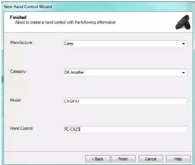
FIG. 20 Advanced Hand Control Wizard dialog
- Select File > New Hand Control to open the Welcome dialog (see FIG. 13 on page 13).
-
Check the Please take me to the advanced screen option to use the advanced wizard dialog:
-
Manufacturer: Select the manufacturer of the hand control from the drop-down list. If the desired manufacturer is not included in the drop-down list, you can manually enter a name in the text field.
- Category: Select the category of the device to be controlled by the selected hand control hand control from the drop-down list. If no device category in the drop-down list adequately describes the device type, you can manually enter a category name in the text field.
- Model: Enter the model number of the device that the selected hand control will control in this text field.
-
Hand Control: Enter the model number of the selected hand control in this text field.
-
Once all fields are populated with information, the Finish button is enabled. Click Finish to save the changes and close the New Hand Control Wizard (Advanced options) dialog.
The hand control file is generated and added to the open User Database file (visible in the Navigator window).
Identify Dialog
Select one or more hand controls in the Search Results window and click Tools > Identify to open the Identify dialog (FIG. 21):

FIG. 21 Identify Dialog
The Identify dialog contains a listing of selected table columns:
| Identify Dialog Options |
| Manufacturer The name of the function's matching manufacturers. |
| Category The categories for the matching functions. |
| Model The model names for the matching functions. |
| Hand Control The name of the matching hand control. |
| Function The function description for the matching function. |
| Channel The corresponding channel for the matching function. |
| Hits The number of times the function has made a match. |
Click on any of the column heading to arrange the fields in either ascending or descending order
The captured function will display in green. Hand controls that have at least one hit but did not match in the current capture will display in blue.
- Capture - This button initiates the Identify session and readies the IRIS to receive functions.
- Remove No Hit - This button will remove all rows that currently contain zero hits.
- Open - This button will open a selected hand control.
- Close - This button closes the Identify dialog.
Using Identify
The Identify feature allows functions to be identified from a list of hand controls. An IRIS connected to the serial port is necessary in order to utilize this feature.
- Perform a search in the Search window (see FIG. 8 on page 11).
- Within the Search Results window, under the Identify column, click on the functions to be added to the Identify list (FIG. 22):
| Manufacturer | Category | Model | Hand Control | Version | Identify |
| Proton | A/V Receiver | AT300 | AS30R | 1 | √ |
| Proton | A/V Receiver | AT300 | AS30R | 2 | √ |
| Proton | A/V Receiver | AT300 | AS30R | 3 | √ |
| Proton | A/V Receiver | AV300 | AS30R | 1 | √ |
| Proton | A/V Receiver | AV300 | AS30R | 2 | √ |
| Proton | A/V Receiver | AV300 | AS30R | 3 | |
| Proton | Cassette Deck | CD300 | AS30R | 1 | |
| Proton | Cassette Deck | CD300 | AS30R | 2 | |
| Proton | Cassette Deck | CD300 | AS30R | 3 | |
| Proton | Compact Disc Change | AC425 | AH482 | 1 | |
| Proton | Compact Disc Change | AC425 | AH482 | 2 |
FIG. 22 Search Results window
- After all desired functions have been selected, select Tools > Identify... to open the Identify dialog.
- Click on the Capture button to begin the identification session (FIG. 23):


FIG. 23 Identify dialog - Capture and remove Not Hit buttons
-
Begin sending functions to IREdit via the IRIS.
-
As the functions are received, found functions will be moved to the top of the list.
- The next function captured will increment the number of hits column and display in green.
- Hand controls with a minimum of one hit but not found in the current capture will display in blue.
- Clicking on the Remove No Hit button will remove all rows that contain no hits.
- Select a hand control and click the Open button to open it into the IR Document window.
Searching for IR Hand Control Files
In addition to using the Navigator window to find an IR hand control file, you can search through a selected directory and open the IR from the Search Results window.
- Select View > Search to show the Search window (see FIG. 8 on page 11).
- In the Navigator window, select a Database directory to search.
- Enter your search criteria into the Search window.
- Click the Search button.
- All matching results will be displayed in the Search Results window. You can scroll through the list to find your desired IR hand control file.
- Upon finding your IR hand control file you can double-click and open it into an IR Document window (see the IR Document Window section on page 8) and populate the Quick List window (see the Quick List Window section on page 12).
NOTE: Use " _ " as a single character wildcard and "%" as a multiple character wildcard. The "_ " symbol will match any single character, and the "%" symbol will match any number of characters.
Cut, Copy And Paste Databases
User defined databases can be both cut and pasted into other user defined databases. Conversely, the AMX database can only be copied.
NOTE: If you are pasting into a new database an entire product hierarchy must first be established.
- Select the hand control file you wish to Copy or Cut.
- Select either Edit > Copy or Edit > Cut.
- Select the user defined database you wish to paste into.
- Select Paste from Edit Menu.
- The new IR node then appears in the user defined database.
NOTE: If you are pasting a complete manufacturer line from the AMX database, it may take a long time, so be patient.
Paste Special
The options in the Paste Special dialog allow you to paste any level of an IR directory into another, with the opportunity to insert any missing information (FIG. 24):

FIG. 24 Paste Special Dialog
- Select the IR, Hand Control Model, Device Model or Category you want to copy in the Navigator window.
- Select Edit > Copy.
- Select the new directory into which you want to paste the selection.
- Select Edit > Paste Special to open the Paste Special dialog. All fields must be filled before you can select OK.
- Either type or select from a drop down menu the Manufacturer and Category information. Type the Device Model and Hand Control Model information.
- Select OK to complete the paste operation.
Viewing an IR Waveform
Select View > Waveform to access the Waveform view box, containing a graphical representation of the waveform associated with the selected IR function.
See the Waveform Window section on page 10 for details.
Editing IR Files
IREdit allows you to edit up to 255 functions within user-created IR files.
NOTE: IR files contained within the AMX Database cannot be edited.
- Values from other hand controls can be cut or copied and then pasted into any one of the 255 function slots.
- After you have made all of your changes you can export your .IRL hand control file. See the Exporting IR Files on Exporting IR Files section on page 25 for more details.
- Double-click on any .IRL file within the Navigator window to open and populate the Properties and IR Document windows.
Editing IR Properties
Right-click on one of the bold items in the Properties window to edit a hand control.
- The Category Name, Template and Manufacturer Name fields provide you with drop down lists to choose from.
- Select one of the items listed or select New and type your own in the window and select OK.
- The Note field is the only one that can be left blank.
NOTE: When the insert key is on, you will see a INS in the lower right corner of the application window. In this mode, existing functions will be moved down when pasting in new functions. When insert is off, OVR will be displayed in the lower right corner of the application window. In this mode, existing functions will be overwritten when new functions are pasted.
Category Manager
Use the Category Manager to manage your categories without expanding the database.
Adding a Category Via Category Manager
- Select a user database file in the Navigator window.
- Select Edit > Categories to open the Category Manager dialog (FIG. 25):

FIG. 25 Category Manager Dialog
- Click Add. This action adds a new (empty) entry to the list of Categories (FIG. 26):
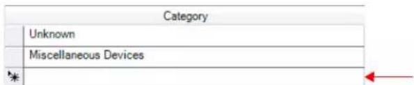
FIG. 26 Category Manager Dialog - New Category Entry
- Place the cursor in the Category field and type the information.
- Once finished, click on the Close button. The new directory will appear in the selected database.
NOTE: Categories can be sorted by clicking on column headers. An arrow appears in the header to indicate ascending or descending order.
Deleting a Category Via Category Manager
- Select a user database file in the Navigator window.
- Select Edit > Categories to open the Category Manager dialog.
- Select the category you want to delete.
- Click on the Delete button.
- Once finished, click on the Close button.
NOTE: Deleting a category will also delete all information contained therein.
Model Manager
Use the Model Manager to manage models without expanding the database.
Adding an IR Property
- Within the Properties window select Model Name.
- Model Name provides a drop-down button, when selected will open the Model Manager dialog (FIG. 27):

FIG. 27 Model Manager Dialog
NOTE: You can only edit directories you have created. The AMX database is read-only.
- Select Add and a new model line will appear (FIG. 28):
| Model | Description | Manufacturer | Category | |
| AT300 | Amplifier/Receiv | Proton | Miscellaneous Devices | |
| Proton | Miscellaneous Devices | |||
FIG. 28 Model Manager Dialog - New Model Entry
- Place the cursor in the Model field and enter a model name.
- Place the cursor in the Description field to enter a description of this model (optional).
- Place the cursor in the Manufacturer field to select from a menu populated with the manufacturers located in your user database.
- Place the cursor in the Category field to select a category from the menu populated with the categories located in your user database.
- Click OK.
Deleting An IR Property
- Within the Properties window select Model Name.
- Model Name provides a drop-down button, when selected will open the Model Manager Dialog.
- Within the Model Manager select the model line to be deleted.
- Select Delete.
- You will be prompted to confirm your selection. Click Yes.
- Afterwards you are returned to Model Manager. Click OK.
Capturing An IR File
With the use of an IRIS, IREdit can capture IRs into hand control functions specified by you.
IRIS Infrared/Serial Data Capture Unit
The IRIS Infrared Capture Unit is a stand-alone, self-contained unit captures infrared (IR) or wired-IR function signals from an IR hand control. For operating instructions on the IRIS, refer to the IRIS Infrared Capture Unit Instruction Manual.
Capture Communication Settings
The connected IRIS must be identified to IREdit.
- Select Tools > Comm Settings to open the Communication Settings dialog (see FIG. 44 on page 32).
- Open the Capture tab (FIG. 29):
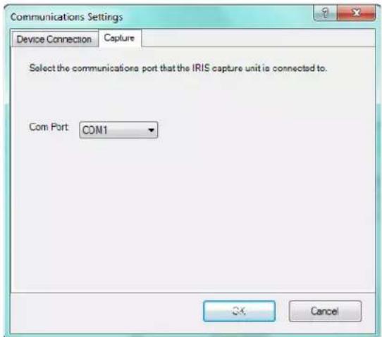
FIG. 29 Communication Settings dialog - Capture tab
- Click the down arrow to open a menu where you can choose between any number of COM ports.
- Click OK.
Capture IR Wizard
- Select Tools > Comm Settings > Capture Tab to set the port location of the IRIS. Select OK.
- In the IR Document window, select the channel into which you want to capture.
- Select Tools > Capture. This will launch the IR Capture Wizard (FIG. 30):

FIG. 30 IR Capture Wizard - Function Name dialog
- Enter the function name and select Next.
- Capture the IR from the hand control:
a. Hold the hand control approximately three inches from the IR capture window.
b. Press and hold down the first key on the hand control to capture the first function.
c. The SIGNAL LED will start blinking.
d. Hold just until the READY LED goes off.
e. When the READY LED comes back on, repeat this step to confirm the IR signal.
- Push the Send button on the IRIS.
- The IR Capture Wizard will confirm the information sent to the slot.
- Click Finish.
Discrete IR Hex Codes
Hex format codes are available only online. Therefore, hex format codes cannot be captured from a manufacturer's remote by an IRIS and added into an .IRN or .IRL/.IRV file.
IREdit utilizes the base format (raw oscillated code) of the hex codes (available at www.remotecentral.com).
Discreet hex codes can be imported into IREdit files via the Discrete IR Hex Codes Wizard.
- Select Tools > Discrete IR Hex Codes to open the Discrete IR Hex Codes Wizard dialog (FIG. 31):

FIG. 31 Discrete IR Hex Codes Wizard dialog
- Enter a function name in the text field and click Next to proceed to the Enter hex format IR code dialog (FIG. 32).
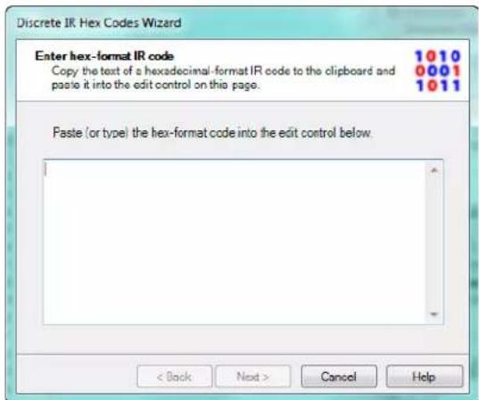
FIG. 32 Discrete IR Hex Codes Wizard - Enter Hex-Format IR Code dialog
- Click Next to proceed to the to the Discrete IR Hex Code Import Complete dialog.
- Click Finish to close the Wizard.
Importing Discrete IR Hex Codes
Discrete IR Hex Codes cannot be captured; therefore, they have to be imported into IREdit projects.
- Open the document view containing the IR file to be edited.
- Select a particular (target) function in the IR document view in order to enable the discrete IR hex import feature.
- Click on Tools > Discrete IR Hex Codes.
- The first page of the wizard prompts for a name for the function. Then click Next.
- The next page of the wizard is a window to enter the Discreet IR Hex codes-format text.
- Paste the code into the text edit field provided by the wizard.
NOTE: The Discrete IR Hex-format code can also be typed in verbatim.
-
When text has been entered into the edit control, the page's Next button will then become enabled. No validation will be performed on the text until the Next button is pressed, which launches the translation process.
-
Click Next to begin translation to AMX-format.
When translating the discrete IR hex-format text, all blank, carriage-return, and line-feed characters will be removed first, so spacing and line arrangement are irrelevant. Since all hex-format codes are composed of four-byte blocks, the number of remaining digit characters must be evenly divisible by four. All digits must be in the hex range 0-9 and A-F (or a-f).
If the input text fails to translate, the program will present an error message box and allow the user to re-enter or edit the input text and try again.
IREdit will attempt to translate the text into the AMX proprietary IR format and write it to the selected function in the .IRN/.IRV file in the same manner as the IRIS capture functionality currently operates.
If the translation operation is successful, the wizard will then proceed to the final page and display the result of the operation.
-
Use the Back button to redo the process or click the Finish button to exit the wizard.
-
Repeat process to add more discrete IR hex code functions.
NOTE: Discreet IR hex-format codes must be either raw oscillated code (first four-byte block = 0000) or raw unmodulated code (first four-byte block = 0100) in order to be translated into the AMX proprietary format.
Importing IR Files
You have the option of importing any of your preexisting .IRL files into a user defined database
- Select the destination database in the Navigation window for the .IRL files.
- Select File Menu > Import IR File(s).... This launches the Import IR dialog (FIG. 33):
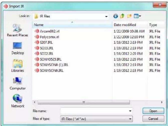
FIG. 33 Import IR dialog
- Select the .IRL files you wish to import and click Open.
- The new .IRL files appears under the database in the Navigator window. Next is the product name, then Imported File. Then the hand control model. Followed by category and finally the address (FIG. 34).

FIG. 34 IRL in Navigator Window
NOTE: Each product name can have an Imported File directory in a given database.
Exporting IR Files
Once you have edited your IR hand control file, you must elect to export it to .IRL format in order to use it in a control device. From there you can bring it into a NetLinx Studio session.
- Select the user defined database file to be exported from the Navigator window.
- Select File Menu > Export IR File(s)...to open the Export dialog (FIG. 35):

FIG. 35 Export dialog
-
You can select exporting by either:
-
the default method of Generated Filename. (Manufacturer,Device,HandcontrolModel,Category,version.irl)
-
use the DOS filename (only available when exporting from the AMX database)
• or naming the file yourself. -
In the Directory to export to field, designate a target directory for the exported.IRL file (browse to a new directory by selecting the browse button).
-
After you have decided the method and directory for export, select OK.
NOTE: When you export in DOS you will only get as many IR files as there are hand controls for that manufacturer. Conversely, when you export via Generated Filename you get as many IR files as there are leaf nodes.
Actuate IR
Select Tools > Actuate to open the Actuate IR dialog (FIG. 36):

FIG. 36 Actuate IR Dialog
| Actuate IR dialog | |
| Device | |
| • Connection Information | Provides basic information on the current device connection |
| • Device:Port:System | Specify Device, Port and System address information in the text fields. |
| • Connection Status Indicates the status of the current device connection. | |
| Channel | |
| • Channel List Select a channel to test from this scrolling list. | |
| • Pulse The Pulse section sets the actuate to pulse OFF and ON at a set interval.• Click Pulse to cause the corresponding LED to flash.• Pulse Interval time field (range is 1 to 100 in tenths of a second). | |
| • Toggle Press to manually actuate the selected IR function from OFF to ON.Click the Off button to turn on the corresponding LED at the master. | |
Actuating an IR Function
You can select a downloaded IR function and then actuate it at the master to confirm a successful download.
- After you have downloaded the IR file to the master, select one of the functions to actuate.
- Select Tools > Actuate to open the Actuate IR dialog.
- Confirm all information listed in the Device section is correct.
- Select one of the Channels in the Channel field.
- Click the Off button. It will then switch to on and the corresponding LED at the master will illuminate.
You can select Pulse to have the master's LED flash at the intervals of the waveform.
The interval between when the channel ON command is sent to the target device and when the channel OFF command is sent can be set in the Pulse interval time field.
The field will accept any value between 1 and 100. The time is measured in tenths of a second.
- Click Close when finished.
NOTE: To actuate other ports, exit back to the IREdit work area and repeat the process.
This restore feature returns all of IREdit's dockable windows to the default arrangement.
Go to View >Restore Default Window Settings to reset the dockable windows.
IR Update Wizard
The IR Update Wizard takes you through the steps necessary to downloading available updates for the AMX IR database. An internet connection is required
- Select Help > AMX IR Update to open the IR Update Wizard (FIG. 37):
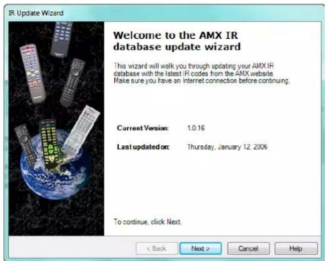
FIG. 37 IR Update Wizard - Welcome dialog
The Welcome dialog indicates the Current Version of the IR database as well as the last date on which the database was updated.
- Click Next to proceed to the Check for Updates dialog (FIG. 38):

FIG. 38 IR Update Wizard - Check For Updates dialog
- The following updates are available - Within this window the IR Update Wizard displays the Manufacturer, Category and Model name of available updates for the database.
-
No updates available at this time - This message is displayed only in the event there are no new updates to the database.
-
Click Next to proceed to the Updating dialog (FIG. 39):

FIG. 39 IR Update Wizard - Updating dialog
The status bar displays the progress of the download and update of the IR files.
- When the update is complete, click Finish to close the wizard.
AMX IR Database Update
AMX is constantly adding IR codes to the database. The database can be updated via AMX IR Update.
- Go to Help > AMX IR Update to launch the IR Update Wizard Dialog.
- Click Next to begin searching for updates.
- If updates are available they will be displayed. Click Next.
- The updates will then begin downloading. Once complete, the Finish button will be available.
- Click Finish.
NOTE: After the update is complete, the AMX IR database will collapse.
Web Update
Newer versions of IREdit can now be acquired via the internet. The Web Update utility accesses the AMX web site with the application ID and version number and searches for updates.
NOTE: The Web Update application is installed separately from IREdit. The install file for Web Update is available to download from www.amx.com.
- Go to Help > Web Update to check for updates.
- If updates are available for the installed version of IREdit they will be downloaded at this time.
- After the download is complete Web Update will close IREdit and the updates will be added.
Navigating using the Windows dialog
Once 10 or more IR hand controls are open the Windows function will be enabled.
To Activate a Window
- Go to Window > Windows... to open the Windows dialog (FIG 40).

FIG. 40 Windows dialog
- Select the hand control under Name.
- Click the Activate button.
To Close a Window
- Go to Window > Windows... to open the Windows dialog.
- Select the hand control(s) under Name.
- Click the Close Window(s) button.
- Click the Close button.
Printing Files
You can print the active IR file using File > Print:
- Choose File > Print Preview to open the Print Preview window (FIG. 41), to preview the file as it will be printed (if necessary).

FIG. 41 Print Preview window
- Choose File > Print to print the file.
Advanced Operations
Custom Toolbars And Commands
Customizing The Toolbars
To add/remove commands from the toolbars (including the Standard toolbar), and any custom toolbars that have been created): Right-click in the toolbar area and selecting Customize from the Customize context menu to open the Customize dialog.
-
Open the Toolbars tab of the Customize dialog. Use the checkboxes next to each toolbar in the list to show/hide the toolbars.
-
To add a toolbar button to a toolbar:
a. Open the Commands tab of the Customize dialog.
b. Select a command Category (on the left side of the tab).
c. Select a Command (on the right side of the tab), and drag-and-drop the selected command onto the toolbar that you want to add it to.
- To remove toolbar buttons from a toolbar, click on any toolbar button, and drag it out of the toolbar area.
Creating A New Custom Toolbar
To create a new custom toolbar:
- Right-click in the toolbar area and selecting Customize from the Customize context menu to open the Customize dialog.
- Open the Toolbars tab of the Customize dialog. Use the checkboxes next to each toolbar in the list to show/hide the toolbars.
- Click the New command button to open the New Toolbar dialog.
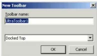
FIG. 42 New Toolbar Dialog
- Enter a name for the new toolbar in the Toolbar Name field.
- Select a placement option from the drop-down list (Docked Top, Docked Bottom, Docked Left, Docked Right, or Floating). The default setting is Docked Top.
- Click OK to save the changes and close the New Toolbar dialog.
- The new (empty) toolbar appears in the workspace according to the placement option specified.
To add commands to the new toolbar refer to Customizing the Toolbars.
Modifying Properties for Existing Toolbar Buttons
To modify various properties of individual toolbar buttons:
- Right-click on the toolbar area and select Customize from the Customize context menu.
- Select the Commands tab in the Customize Dialog.
-
Select a toolbar button (in the Toolbar area of the work area) to enable the Modify Selection drop down menu. The options in this menu allow you to make any of the following modifications to the selected toolbar button:
-
Reset - Returns all values of the command to the default settings.
- Delete - Removes the command from the toolbar.
- Name - Change the name associated with the command. Mouse over Name and it will enable the text field to the right. Now highlight and edit the text.
- Default Style - Toolbar appearance is icon and text description is provided upon mouse over.
- Text Only (Always) - Toolbar appearance is text description only.
- Text Only (in Menus) - Text description only in drop down menus.
- Image and Text - Toolbar appearance is icon and text description.
- Begin a Group - Places a division marker at the beginning and then at the end of a user specified group of commands.
-
Recently Used - Default is to show the recently used file name. Remove check to turn off selection.
-
Once you have made all of your changes, select Close.
Assigning Shortcuts to Commands
Use the options in the Customize Keyboard dialog to assign shortcut keys to commands.
- Right-click on the toolbar and select Customize from the Customize context menu.
-
Within the Customize Dialog select the Keyboard command button to open the Customize Keyboard dialog.
-
Select a category in the Categories view.
- Under Commands, find your selection.
- Choose the shortcut you would like to associate in the Specify a Shortcut drop down menu.
- Click Assign.
- Click Close.
Setting Preferences
The Preferences dialog allows for behavioral changes to be made to the application.

FIG. 43 Preferences Dialog
Undo/Redo Support
No undo/redo support is available unless it is enabled in the Preferences dialog. To enable:
- Go to Edit > Preferences...
- In the Undo/Redo Support section, place a check in the box next to Enable the Undo/Redo system.
- Under Number of Undo/Redo levels: place the amount of actions to track.
- Select OK.
Preserving Spaces for Copied Functions
By default, functions copied within a hand control or to another hand control will not keep spaces that may occur between the functions. For example, channels 1, 2 and 5 will be copied into channels 1, 2 and 3. Preserve spaces when copying functions must be enabled for the spaces to be included when copying functions. For example, channels 1, 2 and 5 will be copied into channels 1, 2 and 5. To enable Preserve spaces when copying functions see below:
- Go to Edit > Preferences... to open the Preferences dialog.
- Under Miscellaneous place a check in the box next to Preserve spaces when copying functions?
- Click the OK button.
Save Window Settings
When this function is enabled the dockable window arrangements will stay intact. To enable Save windows settings on exit see below:
- Go to Edit > Preferences... to open the Preferences dialog.
- Under Window/Workspace Settings place a check in the box next to Save window settings on exit?
- Click the OK button.
Enabling Restore Workspace on Startup
When enabled, documents that were previously open in the Navigator window will reopen upon startup of IREdit. To enable:
- Go to Edit > Preferences... to open the Preferences dialog.
- Under Window/Workspace Settings place a check in the box next to Restore workspace on startup?
- Click the OK button.
Auto Template Capture
When enabled IREdit will automatically advance to the next function in the template after a successful IR capture.
- Go to Edit > Preferences...
- Under IRCapture place a check in the box next to Auto Template Capture.
- Click the OK button.
Skip Finish Page
When enabled IREdit will skip the Finish page of the IR capture process and instead return to the Start page of IR capture.
- Go to Edit > Preferences...
- Under IR Capture place a check in the box next to Skip Finish Page.
- Click the OK button.
Communications and File Transfers
Communications Settings
Use the options in the Communications Settings dialog to specify communication settings for transfer operations:
- Select Tools > Comm Settings... to open the Communications Settings dialog (FIG. 44):

FIG. 44 Communications Settings Dialog
- Select NetLinx Master (default setting) or Axcess Master as the Platform Selection.
- Select TCP/IP, Serial, Modem or Virtual NetLinx Master as the Transport Connection Option.
-
Click Settings to open the appropriate Settings dialog (based on the selected Transport Connection Option):
-
TCP/IP Settings dialog - see page 33.
-
Serial Port Settings dialog - see page 33.
• Modem Port Settings dialog - see page 34.
• Virtual NetLinx Master Settings dialog - see page 34. -
If the target NetLinx Master requires authentication to connect, select Authentication Required. This selection activates the User Name and Password button - click to open the Master Controller User Name and Password dialog (FIG. 45):

FIG. 45 Master Controller User Name and Password dialog
Enter the required login credentials and click OK.
TCP/IP Settings dialog
With TCP/IP selected as the Transport Connection Option, click Settings in the Communications Settings dialog to open the TCP/IP Settings dialog (FIG. 46):
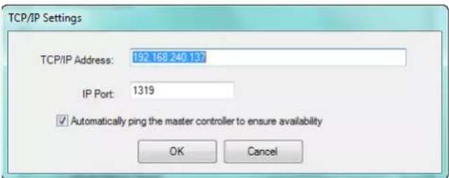
FIG. 46 TCP/IP Settings dialog
| TCP/IP Settings dialog Options | |
| TCP/IP Address Enter a valid target TCP/IP Address. | |
| IP Port The IP Port assignment defaults to 1319.You should not change the IP Port number. | |
| Automatically ping the master controller to ensure availability | This option prompts the program to ping the target IP address to ensure that the Master is available. |
| OK Click to save changes and close this dialog. | |
| Cancel Click to discard changes and close this dialog. | |
Serial Port Settings dialog
With Serial selected as the Transport Connection Option, click Settings in the Communications Settings dialog to open the Serial Port Settings dialog (FIG. 47):

FIG. 47 Serial Port Settings dialog
| Serial Port Settings dialog Options | |
| Com Port Click | the down arrow to open a menu where you can choose between available COM ports. |
| Baud Rate | Click the down arrow to open a menu where you can choose the baud rate of your COM port from the list (suggested setting = 38400). |
| Data Bits Click | the down arrow to open a menu where you can choose the Data Bits (suggested setting = 8). |
| Parity Click the | down arrow to open a menu where you can choose the parity (suggested setting = none). |
| Stop Bits Click | the down arrow to open a menu where you can choose the Stop bit(s) (suggested setting = 1). |
| Flow Control Click | the down arrow to open a menu where you can choose the Flow Control (suggested setting = none). |
| OK Click to save changes and close this dialog. | |
| Cancel Click to | discard changes and close this dialog. |
Modem Port Settings dialog
With Modem selected as the Transport Connection Option, click Settings in the Communications Settings dialog to open the Modem Port Settings dialog (FIG. 48):

FIG. 48 Modem Port Settings dialog
| Modem Port Settings dialog Options | |
| Com Port Click the down arrow to open a menu where you can choose between available COM ports. | |
| Baud Rate | Click the down arrow to open a menu where you can choose the baud rate of your COM port from the list (suggested setting = 38400). |
| Data Bits Click the down arrow to open a menu where you can choose the Data Bits (suggested setting = 8). | |
| Parity Click the down arrow to open a menu where you can choose the parity (suggested setting = none). | |
| Stop Bits Click the down arrow to open a menu where you can choose the Stop bit(s) (suggested setting = 1). | |
| Flow Control Click the down arrow to open a menu where you can choose the Flow Control (suggested setting = none). | |
| Phone Number Enter the phone number to be dialed for connection. | |
| OK Click to save changes and close this dialog. | |
| Cancel Click to discard changes and close this dialog. | |
Virtual NetLinx Master Settings dialog
With Virtual NetLinx Master selected as the Transport Connection Option, click Settings in the Communications Settings dialog to open the Virtual NetLinx Master Settings dialog (FIG. 48):

FIG. 49 Virtual NetLinx Master Settings dialog
| Virtual NetLinx Master Settings dialog Options | |
| VNM System Number Set the system number to a value between 1 and 65535. | |
| OK Click to save changes and close this dialog. | |
| Cancel Click to discard changes and close this dialog. |
Sending an IR File
- Select an IR File in the Navigator window (FIG. 50):

FIG. 50 IR File selected in the Navigator window
- Select Tools > Send or click the toolbar button. This action prompts IREdit to make the device connection specified in the Communications Settings dialog (FIG. 51).

FIG. 51 Connecting dialog
- Once the connection has been established, the Send IR dialog is opened (FIG. 52):

FIG. 52 Send IR dialog
- Enter the address information for Device, Port and System.
- Click Start to begin the transfer operation.
Virtual NetLinx Master Transfers
IREdit supports direct connection to G4 panels (via USB), for situations where the target panel is not connected to a NetLinx Master. In this situation, you can use your PC's USB connection to connect directly to the panel, using your PC as a Virtual NetLinx Master. There are three basic steps to Virtual NetLinx Master file transfers:
- Configuring the Touch Panel for Virtual NetLinx Master Transfers
- Configure IREdit for Virtual NetLinx Master transfers
- Transfer the Files Using a Virtual NetLinx Master connection
Configure the Touch Panel for Virtual NetLinx Master Transfers
If it is not already powered up and connected, apply power to the touch panel and verify that it is connected to USB connector on the panel. To configure the panel for Virtual NetLinx Master transfers:
- Press and hold the Front Setup Access button (below the touch screen) for 3 seconds to access the Setup page (FIG. 53):

FIG. 53 Touch Panel Setup Page
- Press the Protected Setup button to access the Protected Setup page (FIG. 54):

FIG. 54 Touch Panel Protected Setup Page
- Use the on-screen keyboard to enter the password (default password = 1988).
- Press the System Connection button to access the System Connection Setup page (FIG. 55):

FIG. 55 Touch Panel System Settings Page
- Under Master Connection. select USB as the Type.
- Press the Back button to return to the Protected Setup page and press the Reboot button to reboot the panel. After several seconds, the panel should appear in the online device tree, listed as Virtual NetLinx Master. Once you can see the device online, you may transfer panel files to the G4 device without the need for an intermediate NetLinx master.
Configuring IREdit for Virtual NetLinx Master Transfers
- Select Tools > Comm Settings... to open the Communications Settings dialog.
- Select the Virtual NetLinx Master radio button.
- Click the Settings button to access the Virtual NetLinx Master Settings dialog (see FIG. 49 on page 34).
- Enter the system number and select OK.
Powering Up and Connecting the Panel
- Verify that an USB cable is connected to the panel.
- Connect the terminal end of the PSN6.5 power cable to the 12 VDC power connector on the rear/side of the touch panel.
Transferring Files Using a Virtual NetLinx Master Connection
Once you have configured both the touch panel and IREdit for Virtual NetLinx Master Transfers, you are ready to transfer files to the panel without the need for an intermediate master:
- With your IR file selected in the Navigator window, select Tools > Send, to open the Send IR dialog (see FIG. 52 on page 35).
- Enter the information for Device, Port and System.
- After you have all the necessary information listed, click Start.
- Once it is done sending you can select Close.
NOTE: Panels cannot send IR data to IREdit via USB.
Receiving an IR File
You can transfer a preexisting IR file from either an Axcess or NetLinx Master directly into IREdit.
- First select a user database in the Navigator window. If you do not have a user database you must create one.
- Select Tools >Receive to open the Receive IR Wizard (FIG 56):

FIG. 56 Receive IR Wizard - Welcome dialog
- Click Next to proceed to the Select Device dialog (FIG. 57):

FIG. 57 Receive IR Wizard - Select Device dialog
- Confirm the connection information in the Device field, and enter the Device, Port and System number.
- Click Next to request the IR data from the targeted device (FIG 58):
NOTE: Place a check next to Please take me to the advanced screen to proceed to the final screen of the wizard after a successful transfer.

FIG. 58 Receive IR Wizard - Transferring IR Data dialog
- Click Next when the wizard reads File transfer complete.
- Enter the name of the Manufacturer or select from the list and click Next.
- Enter the name of the Category or select from the list and click Next.
- Enter the name of the Hand Control Model and click Next.
- Enter the name of the Model and click Next.
- Confirm all information listed on the Finished screen
- Click Finish.
Get Available Memory
When sending an IR file to a master you can first check the available memory of that port via the Get Available Memory function:
- Select Tools > Send...
- In the Send IR dialog, select Get Available Memory.
- If the port is functioning properly you will receive an amount of available memory.
NOTE: The first 4 ports and the last 4 ports of a NetLinx system share memory. The available memory reported from the Get Available Memory is a reflection of all 4 ports. All ports share the same available memory in Axcess.
NI-series devices (NI-2000, NI-3000, NI-4000) always return the value 32768 in response to a "Get Available Memory" request, regardless of the port queried.
Verifying IR
Verifying is a means of ensuring no corruption occurred to your hand control file during the sending to the Master. Verify will compare all functions in the hand control file on the Master's port to the functions listed in IREdit's hand control selected in the Navigator window. In order to verify you must first send a hand control file.
- Select Tools > Verify. This launches the Verify IR Wizard (FIG. 59):
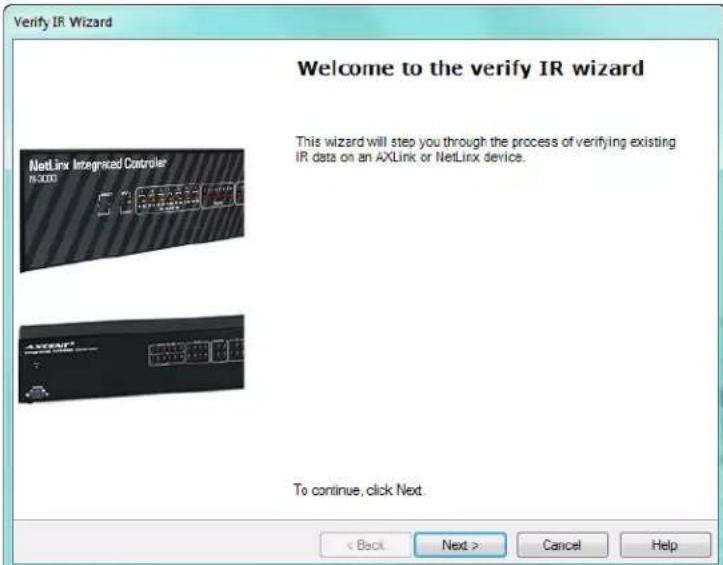
FIG. 59 Verify IR Wizard - Welcome dialog
- Select Next to proceed to the Select Device dialog (FIG. 60):

FIG. 60 Verify IR Wizard - Select Device dialog
- Designate the Device, Port and System.
- Select Next to proceed to the Transferring IR Data dialog (FIG 61):
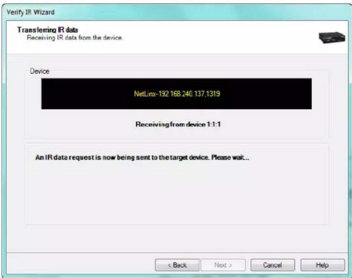
FIG. 61 Verify IR Wizard - Transferring IR Data dialog
- Confirm the proper hand control is selected in the Navigator window.
- Select Next.
- The hand control is received from the Master.
- Select Next to proceed to the Finished dialog. This dialog lists the Manufacturer, Category, Device Model and Hand Control Model. The message screen below will read either, "Verification Successful" or "Verification Failed."
Setting Program Preferences
Customizing The Toolbars
You can customize the toolbar by right-clicking on the standard toolbar area and selecting Customize from the Customize context menu. The three tabs available in the Customize dialog are:
- Toolbars Tab
- Commands Tab
- Options Tab
Too I b ars Tab
The Toolbars Tab of the Customize dialog allows you to create a new toolbar populated with commonly used tasks. You can control which toolbars are visible in addition to managing them.

FIG. 62 Toolbars Tab within Customize Dialog
To access the Customize dialog right-click anywhere on the standard toolbar area to open the customize context menu. Select the Customize option. Use the options in this dialog to create and manage toolbar properties.
- Select New to initiate a new toolbar which will then prompt you to name it. After that you can designate the functions to be found on the toolbar.
- Select Rename to change the name of your customized toolbar. The standard toolbar cannot be renamed.
- Select Delete to delete custom toolbars. The standard toolbar cannot be deleted.
- Reset will return selected toolbars to default settings.
Click the Keyboard command button to customize your own quick key strokes for commonly used functions.
Commands Tab
Functions for populating the toolbars are located on the Commands Tab of the Customize dialog.

FIG. 63 Commands Tab within Customize Dialog
Right-click and select Customize from the Customize context menu to access this dialog. You can toggle the view from All Commands, File (related functions), Unassigned (functions outside of Edit, File and View), and View (functions related to the setup of the work area).
The related commands are located in the Commands window to the right of the Categories field. Selecting Description when a command is highlighted will provide information for that particular function. If the function contains additional parameters, the Modify Selection option will be enabled when a particular command is highlighted.
Options Tab
The Options Tab of the Customize dialog allows you to alter the look of the toolbar including the size of the icons that populate it.

FIG. 64 Options Tab within Customize Dialog
Personalized Menus and Toolbars
- Always show full menus - When checked, drop down menus will show all available commands.
- Show full menus after a short delay - used in conjunction with Always show full menus, checked will display all available commands within a drop down menu after a delay.
- Reset my usage data - select this button to restore default appearances of the toolbars. This will not remove any custom toolbars. You will be prompted to confirm this change.
Other
- Large Icons on Menus - When checked, large icons will appear inside the drop down menus.
- Large Icons on Toolbars - When checked, large icons will appear on the toolbar.
- Show Screen Tips on toolbars - When selected, text description will appear when you mouse over commands.
- Show shortcut keys in Screen Tips - When selected, if there is a shortcut key associated with the command it will appear upon mouse over.
- Floating Toolbar Fade Delay (in milliseconds) - Toolbars not docked will fade partially out after your designated time and return to view when selected
- Menu Animations - You can choose from Fade, Slide, Unfold, Random and None for Menu Animations.
Customize Keyboard Dialog
Shortcut keys can be assigned and reassigned to user specified commands.
![Customize Keyboard Specify a Command Categories: All Commands File View Commands: Close Exit Export... Import... Open... Specify a Shortcut Ctrl+O Currently assigned to: [unassigned] Description Assign Remove Reset All... Close](/content/2026/05/982654/images/58d7de3058e8186c1535096978aba365dd454671d227b6e654a05c082937789b.jpg)
FIG. 65 Customize Keyboard Dialog
Categories:
- All Commands - This selection will display all commands under the Commands view.
- Edit - This selection will display only the commands associated with the Edit menu in the Commands view.
- File - This selection will display only the commands associated with the File menu in the Commands view.
- Help - This selection will display only the commands associated with the Help menu in the Commands view.
- Tools - This selection will display only the commands associated with the Tools menu in the Commands view.
- View - This selection will display only the commands associated with the View menu in the Commands view.
- Window - This selection will display only the commands associated with the Window menu in the Commands view.
Commands - List of commands associated with a shortcut.
Specify a Shortcut - A drop down list of shortcuts that can be associated to the commands.
Currently assigned to: - In the event a shortcut is already assigned to the shortcut it will be displayed.
Description - A read-only message of attributes associated with the selected command.
- Assign - Confirms changes made to commands.
- Remove - Deletes shortcut associated to command.
- Reset All - Deletes all changed shortcuts and returns them to the default settings.
- Close - Closes the Customize Keyboard dialog.
- IMPORTANT SAFETY INSTRUCTIONS
- COPYRIGHT NOTICE
- LIABILITY NOTICE
- AMX WARRANTY AND RETURN POLICY
- Table of Contents
- IREdit IR Library Management ....6
- Basic Operations 13
- Advanced Operations 29
- Communications and File Transfers 32
- IREdit IR Library Management
- Overview
- Supported Platforms
- IREdit operates on:
- Other PC requirements:
- The IREdit Work Area
- IREdit Windows
- Working With Dockable Windows
- IR Document Window
- Properties Window
- Templates
- Waveform Window
- Navigator Window
- Search Window
- Search Results Window
- Quick List Window
- Basic Operations
- Creating a New IR Database
- Creating a New Hand Control File
- Using the New Hand Control Wizard
- Advanced Hand Control Wizard Dialog
- Identify Dialog
- Using Identify
- Searching for IR Hand Control Files
- Cut, Copy And Paste Databases
- Paste Special
- Viewing an IR Waveform
- Editing IR Files
- Editing IR Properties
- Category Manager
- Adding a Category Via Category Manager
- Deleting a Category Via Category Manager
- Model Manager
- Adding an IR Property
- Deleting An IR Property
- Capturing An IR File
- IRIS Infrared/Serial Data Capture Unit
- Capture Communication Settings
- Capture IR Wizard
- Discrete IR Hex Codes
- Importing Discrete IR Hex Codes
- Importing IR Files
- Exporting IR Files
- Actuate IR
- Actuating an IR Function
- IR Update Wizard
- AMX IR Database Update
- Web Update
- Navigating using the Windows dialog
- To Activate a Window
- To Close a Window
- Printing Files
- Advanced Operations
- Custom Toolbars And Commands
- Customizing The Toolbars
- Creating A New Custom Toolbar
- Modifying Properties for Existing Toolbar Buttons
- Assigning Shortcuts to Commands
- Setting Preferences
- Undo/Redo Support
- Preserving Spaces for Copied Functions
- Save Window Settings
- Enabling Restore Workspace on Startup
- Auto Template Capture
- Skip Finish Page
- Communications and File Transfers
- Communications Settings
- TCP/IP Settings dialog
- Serial Port Settings dialog
- Modem Port Settings dialog
- Virtual NetLinx Master Settings dialog
- Sending an IR File
- Virtual NetLinx Master Transfers
- Configure the Touch Panel for Virtual NetLinx Master Transfers
- Configuring IREdit for Virtual NetLinx Master Transfers
- Powering Up and Connecting the Panel
- Transferring Files Using a Virtual NetLinx Master Connection
- Receiving an IR File
- Get Available Memory
- Verifying IR
- Setting Program Preferences
- Too I b ars Tab
- Commands Tab
- Options Tab
- Customize Keyboard Dialog
- Categories:
Brand : AMX
Model : IREdit
Category : Infrared remote