
4K22A-HS - Video projector Christie - Free user manual and instructions
Find the device manual for free 4K22A-HS Christie in PDF.


| Product Type | Video Projector |
| Brand | Christie |
| Model | 4K22A-HS |
| Display Technology | 3DLP |
| Native Resolution | 4K UHD (3840 x 2160) |
| Brightness | 22,000 Lumens |
| Light Source | Laser Phosphor |
| Lamp Life | 20,000 hours (typical) |
| Contrast Ratio | 2,000,000:1 |
| Dimensions (W x D x H) | 24.0 x 20.5 x 8.7 inches (610 x 520 x 221 mm) |
| Weight | 55.1 lbs (25 kg) |
| Power Consumption | 1,500 W (max) |
| Inputs | HDMI x2, DisplayPort, HDBaseT, 3G-SDI |
| Outputs | 3G-SDI, USB for service |
| Control Interface | Ethernet, RS232, IR, Wired Remote |
| Lens Compatibility | Interchangeable lenses (optional) |
| 3D Capability | Yes (active shutter) |
| Operating Temperature | 40°F to 104°F (5°C to 40°C) |
| Recommended Maintenance | Clean air filters every 500 hours; replace laser module at end of life |
| Spare Parts Availability | Authorized service centers; key modules (laser, power supply) replaceable |
| Safety Certifications | Class 4 laser product; CE, FCC, UL listed |
Frequently Asked Questions - 4K22A-HS Christie
User questions about 4K22A-HS Christie
0 question about this device. Answer the ones you know or ask your own.
Ask a new question about this device
Download the instructions for your Video projector in PDF format for free! Find your manual 4K22A-HS - Christie and take your electronic device back in hand. On this page are published all the documents necessary for the use of your device. 4K22A-HS by Christie.
USER MANUAL 4K22A-HS Christie
Christie HS Series 4K
CHRISTIE®
NOTICES
COPYRIGHT AND TRADEMARKS
Copyright © 2023 Christie Digital Systems USA, Inc. All rights reserved.
All brand names and product names are trademarks, registered trademarks or trade names of their respective holders.
GENERAL
Every effort has been made to ensure accuracy, however in some cases changes in the products or availability could occur which may not be reflected in this document. Christie reserves the right to make changes to specifications at any time without notice. Performance specifications are typical, but may vary depending on conditions beyond Christie's control such as maintenance of the product in proper working conditions. Performance specifications are based on information available at the time of printing. Christie makes no warranty of any kind with regard to this material, including, but not limited to, implied warranties of fitness for a particular purpose. Christie will not be liable for errors contained herein or for incidental or consequential damages in connection with the performance or use of this material. Our centers of excellence for manufacturing in Kitchener, Ontario, Canada and in Shenzhen, China are ISO 9001:2015 Quality Management System-certified.
Christie is committed to making our documents free from language bias; however, we are not responsible for the language used on any linked or third-party documentation.
For the most current technical documentation and office contact information, visit www.christiedigital.com.
WARRANTY
Products are warranted under Christie's standard limited warranty, the details of which are available at https://www.christiedigital.com/help-center/warranties/ or by contacting your Christie dealer or Christie.
PREVENTATIVE MAINTENANCE
Preventative maintenance is an important part of the continued and proper operation of your product. Failure to perform maintenance as required, and in accordance with the maintenance schedule specified by Christie, will void the warranty.
REGULATORY (if applicable)
The product has been tested and found to comply with the limits for a Class A digital device, pursuant to Part 15 of the FCC Rules. These limits are designed to provide reasonable protection against harmful interference when the product is operated in a commercial environment. The product generates, uses, and can radiate radio frequency energy and, if not installed and used in accordance with the instruction manual, may cause harmful interference to radio communications. Operation of the product in a residential area is likely to cause harmful interference in which case the user will be required to correct the interference at the user's own expense. Changes or modifications not expressly approved by the party responsible for compliance could void the user's authority to operate the equipment.
CAN ICES-003 (A) / NMB-003 (A)
The product is designed and manufactured with high-quality materials and components that can be recycled and reused. This symbol × means that electrical and electronic equipment, at their end-of-life, should be disposed of separately from regular waste. Please dispose of the product appropriately and according to local regulations. In the European Union, there are separate collection systems for used electrical and electronic products.
If printing this document, consider printing only the pages you need and select the double-sided option.
Please help us to conserve the environment we live in!
NOTATION
Learn the hazard and information symbols used in the product documentation.

Danger! If not avoided, the following could result in death or serious injury.

Warning! If not avoided, the following could result in death or serious injury.

Caution! If not avoided, the following could result in minor or moderate injury.

Notice. If not avoided, the following may result in equipment or property damage.
Content
Introduction 8
Models 8
Safety and warning guidelines 8
AC/power precautions 9
Installation safety and warning guidelines 9
Laser safety precautions 9
Light intensity hazard distance 10
Product labels 12
Projector overview 14
Contact your dealer 14
Key features 14
How the projector works 15
List of components 15
Product documentation 16
Related documentation 16
Technical support 16
Additional information 17
Installation and setup 18
Site requirements 18
Physical operating environment 18
Power connection 18
Projector components 19
Front view 19
Rear view 19
Left view 20
Right view 20
Built-in keypad 21
Input/output (I/O) panel 22
IR remote keypad 23
Positioning the display 25
Turning on the projector 26
Turning off the projector 26
LED status indicator 27
Status LED 27
Shutter LED 27
Adjusting the size and position 28
Setting the image size preset 28
Setting the digital size of display image 29
Setting the digital position of display image 29
Geometry correction 29
Enabling geometry correction 29
Saving geometry correction 29
Applying geometry correction 30
Enabling basic image blending 30
Blending multiple images 31
Downloading a blend from the projector memory 31
Adjusting horizontal keystone 32
Adjusting the vertical keystone 32
Adjusting horizontal pincushion 32
Adjusting vertical pincushion 33
Adjusting 4-corner 33
Enabling auto warp filter 33
Adjusting warp filter 34
Resetting geometry correction setting 34
Configuring warp and blend 34
Warping an image 34
Downloading a warp from the projector memory 35
Performing auto warp and blend 35
Adjusting the image settings 36
Adjusting the brightness 36
Adjusting the contrast 36
Adjusting the color space 36
Adjusting the image sharpness 37
Setting up 3D display 37
Setting 3D mode 37
Setting 3D format 37
Inverting 3D signal 38
Selecting the 3D sync input signal 38
Setting the 3D sync output signal 39
Setting the frame delay 39
Setting the sync delay 39
Configuring the video settings 39
Adjusting black and white video 39
Adjusting the color balance 40
Configuring picture settings 40
Applying customized user configuration setting 41
Editing customized picture setting 41
Setting the contrast ratio 42
Enabling the image freeze 42
Setting the high dynamic range 43
Adjust the color of the image 43
Adjusting primary colors 44
Setting the wall color 45
Setting the wall color automatically 45
Adjusting the image settings automatically 45
Adjusting the image with automatic focus 45
Setting the wall color automatically 46
Balancing the image color automatically 46
Adjusting advanced image settings 47
Adjusting the color value based on gamma setting 47
Adjusting the white peaking 47
Adjusting the color temperature 47
Saving user settings for data recovery 48
Configuring system settings 49
Changing the language 49
Adjusting lens settings 49
Viewing the lens type 49
Aligning the image with focus, zoom, and auto focus ....50
Adjusting the image with automatic focus 50
Adjusting lens position 50
Saving lens setting 51
Applying the previous lens setting 51
Locking the lens motor 51
Resetting the lens to home position 51
Selecting screen image orientation 52
Adjusting on-screen display menus 52
Determining the on-screen display position 52
Showing messages 52
Setting the transparency of the on-screen display position 53
Changing the splash screen 53
Setting time out for on-screen display 53
Setting up password protection ....54
Changing password 54
Setting up power mode 54
Setting the standby mode 54
Setting the AC power 55
Setting the time for auto shutdown 55
Setting the sleep timer 55
Enabling high altitude setting 55
Setting the projector communication 56
Enabling the 12V Trigger 56
Configuring communications 57
Setting network environment 57
Adjusting LAN setting 57
Using the web interface 58
Logging on to the web user interface .....58
Setting the system notification 58
Using the RS-232C interface 59
Re-connecting the network 59
Adjusting WLAN setting 60
Adjusting network setting 60
Setting serial port baud rate 60
Enabling serial port echo 60
Setting the projector address 61
Adjusting the back light settings 61
Setting the hot key 61
Configuring date and time settings 62
Scheduling events 62
Setting up a schedule 63
Configuring light settings 65
Setting light source mode 65
Adjusting the light power 66
Diagnostic tools 67
Viewing projector information 67
Selecting a test pattern 67
Restoring factory default settings 68
Configuring input settings 69
Setting main input source 69
Setting second input source 69
Enabling second input source 69
Swapping main input and second input source 70
Setting the size of second input source 70
Setting up the display layout with two input sources 70
Input sources layout and size 70
Setting the timing detection mode 71
Setting the input searching method 71
Setting up the backup input 72
Adjusting the sub image 72
Enabling low latency mode 72
Configuring the EDID setting 73
Configuring the HDMI output 73
Signal connectivity specifications 74
HDMI1/HDMI2 video formats 75
Display Port video formats 78
12G-SDI video formats 81
HDBaseT video formats 82
Picture-in-picture/picture-by-picture (PIP/PBP) compatibility 85
Regulatory 86
Safety 86
Laser safety 86
Electro-magnetic compatibility 86
Emissions 86
Immunity 87
California law on security 87
Environmental 87
Introduction
This manual is intended for Christie-qualified installers and trained operators of the projector.
For complete HS Series 4K product documentation and technical support, go to www.christiedigital.com.
This projector is intended for use in a non-cinema environment.
Models
The following models are supported for the HS Series 4K.
• 4K13-HS
• 4K13A-HS
- 4K22-HS
- 4K22A-HS
Safety and warning guidelines
This projector must be operated in an environment that meets the operating range specification. Use only the attachments and/or accessories recommended by Christie. Use of others may result in the risk of fire, shock, or personal injury.

Warning! If not avoided, the following could result in death or serious injury.
- Do not expose the product to moisture.
- Do not operate the product without all of its covers in place.
- This product must be installed within a restricted access location not accessible by the general public.
- Only personnel who are trained on the precautions for the restricted access location can be granted entry to the area.
- FIRE HAZARD! Keep hands, clothes, and all combustible material away from the concentrated light beam of the projector.
- TRIP OR FIRE HAZARD! Position all cables where they cannot contact hot surfaces, be pulled, be tripped over, or damaged by persons walking on or objects rolling over the cables.
- SHOCK HAZARD! Disconnect the product from AC before installing, moving, servicing, cleaning, removing components, or opening any enclosure.
- A minimum of two people or appropriately rated lift equipment is required to safely lift, install, or move the product.
- OPTICAL RADIATION HAZARD! Disconnect the power plug from the AC outlet if the product is not being used for an extended period of time.
- Do not allow anything to rest on the power cord.
• Always provide proper ventilation for the product to prevent overheating.

Caution! If not avoided, the following could result in minor or moderate injury.
- Only Christie-qualified technicians are permitted to open product enclosures.
- All procedures must be performed by Christie-qualified technicians.

Notice. If not avoided, the following may result in equipment or property damage.
- Always use a lens plug when installing or moving the product. This prevents contaminants from entering the product.
- Only use cleaning solutions recommended by Christie. All other cleaning solutions may cause product damage and void the warranty.
AC/power precautions
Read all safety and warning guidelines before powering on the projector.

Warning! If not avoided, the following could result in death or serious injury.
- FIRE HAZARD! Do not use a power cord, harness, or cable that appears damaged.
- FIRE OR SHOCK HAZARD! Do not overload power outlets and extension cords.
- SHOCK HAZARD! Only use the AC power cord provided with the product or recommended by Christie.
- FIRE AND SHOCK HAZARD! Do not attempt operation unless the power cord, power socket, and power plug meet the appropriate local rating standards.
- SHOCK HAZARD! Do not attempt operation if the AC supply is not within the specified voltage and current, as specified on the license label.
- SHOCK HAZARD! The AC power cord must be inserted into an outlet with grounding.
- SHOCK HAZARD! Disconnect the product from AC before installing, moving, servicing, cleaning, removing components, or opening any enclosure.
- Install the product near an easily accessible AC receptacle.
Installation safety and warning guidelines
Read all safety and warning guidelines before installing the projector.
Laser safety precautions
Read all safety and warning guidelines before installing or operating the projector.

Warning! If not avoided, the following could result in death or serious injury.
- LASER RADIATION HAZARD! This projector has a built-in Class 4 Laser module. Never attempt to disassemble or modify the laser module.
- Any operation or adjustment not specifically instructed in the User manual creates the risk of hazardous laser radiation exposure.
- Do not operate the product without all of its covers in place.
- Do not look directly into the lens when the light source is on. The extremely high brightness can cause permanent eye damage.
- Only Christie-qualified technicians who are knowledgeable about the hazards associated with laser use, high-voltage, and high temperatures generated by the product are authorized to assemble, install, and service the Christie Laser Projection System.
- Do not look directly into the lens when the light source is on. The extremely high brightness can cause permanent eye damage. Class 1 laser product of IEC/EN 60825-1:2014 and Risk Group 2 according to IEC 62471-5:2015.

Warning! If not avoided, the following could result in death or serious injury.
- Install the product so users and the audience cannot enter the restricted area at eye level.
- Install the product out of reach.
- LASER RADIATION! Do not look directly into the laser beam of the remote.
- Complies with 21 CFR 1040.10 and 1040.11 except for conformance as a Risk Group 2 LIP as defined in IEC 62471-5:Ed. 1.0. For more information see Laser Notice No. 57, dated May 8, 2019. IEC 60825-1:2014: CLASS 1 LASER PRODUCT - RISK GROUP 2.
- For 4K13-HS, 4K13A-HS, 4K22-HS, and 4K22A-HS, no direct exposure to the beam shall be permitted, RG3 IEC 62471-5 when installed with 140-110103-XX lens (throw ratio 1.5-2.0) or of a higher Throw ratio lens.
Light intensity hazard distance
This projector has been classified as Risk Group 3 according to the IEC 62471-5:2015 standard due to possible hazardous optical and thermal radiation being emitted.

Warning! If not avoided, the following could result in death or serious injury.
- PERMANENT/TEMPORARY BLINDNESS HAZARD! No direct exposure to the beam must be permitted.
- PERMANENT/TEMPORARY BLINDNESS HAZARD! Operators must control access to the beam within the hazard distance or install the product preventing potential exposure of the spectators' eyes from being in the hazard distance. Hazard zone shall be no lower than 3.0 meters (9.8 feet) above the floor. In addition, horizontal clearance to the hazard zone shall be a minimum 2.5 meters (8.2 feet).
- EXTREME BRIGHTNESS! Do not place reflective objects in the product light path.
The following diagram shows the zones for optical and skin hazard distances:
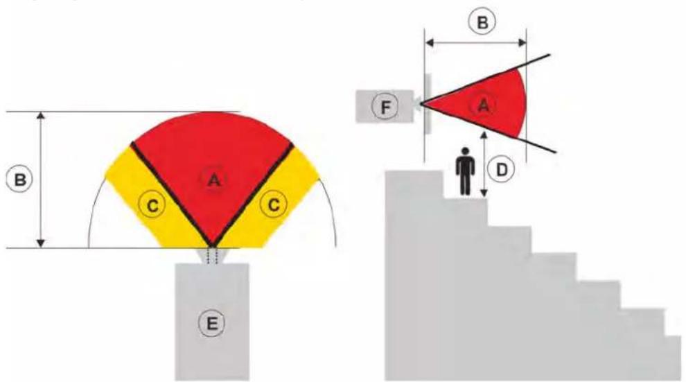
- A—Hazard zone. The region of space where the projection light from the laser illuminated projector is above emission limits for Risk Group 3. The light intensity may cause eye damage after a momentary or brief exposure (before a person can avert his or her eyes away from the light source). The light may cause skin burns to occur.
- B—Hazard distance. Operators must control access to the beam within the hazard distance or install the product preventing potential exposure of the spectators' eyes from being in the hazard distance.
- C—No access zone. Horizontal clearance of the no access zone shall be a minimum of 2.5 meters (8.2 feet).
- D—Vertical distance to hazard zone. The hazard zone shall be no lower than 3.0 meters (9.8 feet) above the floor.
• E—Represents the top view of the projector. - F—Represents the side view of the projector.
For information detailing the hazard distance for each lens, refer to the Christie HS Series 4K Installation and Setup Guide (P/N: 020-002055-XX).
For installations in the United States
The following must be in place for laser-illuminated projector installations in the United States:
- Any human access to the hazard zone, if applicable, must be restricted by barriers to enforce the no access zone.
-
Permanent show installations containing Risk Group 3 laser-illuminated projectors must meet the following conditions:
-
Installed by Christie or by Christie-authorized and trained installers. Refer to the EXTERNAL - Laser safety awareness training (Course code: CS-ELSA-01) on the http://www.christieuniversity.com site.
- Performed according to instructions provided by Christie.
- Ensure the projection system is securely mounted or immobilized to prevent unintended movement or misalignment of the projections.
- Temporary show installations containing Risk Group 3 laser-illuminated projectors may be installed by Christie or sold or leased only to valid laser light show variance holders (laser light show manufacturers) for image projection applications. Such manufacturers may currently hold a valid variance for production of Class IIIb and IV laser light shows and/or for incorporation of the Risk Group 3 laser-illuminated projectors into their shows. This requirement applies also to dealers and distributors of these laser-illuminated projectors.
- The Christie Laser Projection System Installation Checklist must be fully completed after the installation and sent to lasercompliance@christiedigital.com. A copy can remain on-site. This checklist can be found as a separate document in the accessory box with the manual.
- Certain US states have additional laser regulatory requirements. Go to www.christiedigital.com for further information.
Product labels
Learn about the labels that may be used on the product. Labels on your product may be yellow or black and white.
General hazards
Hazard warnings also apply to accessories once they are installed in a Christie product that is connected to power.
Fire and Shock Hazard
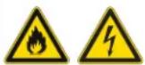
To prevent fire or shock hazards, do not expose this product to rain or moisture.
Do not alter the power plug, overload the power outlet, or use it with extension Cords.
Do not remove the product enclosure.
Only Christie-qualified technicians are authorized to service the product.
Electrical Hazard

Risk of electric shock.
Do not remove the product enclosure.
Only Christie-qualified technicians are authorized to service the product.

General hazard.

Electric shock hazard. To avoid personal injury, disconnect all power sources before performing maintenance or service.

Electrocution hazard. To avoid personal injury, always disconnect all power sources before performing maintenance or service procedures.

Fire hazard. To avoid personal injury and property damage, follow the instructions provided in this document.

Hot surface hazard. To avoid personal injury, allow the product to cool for the recommended cool down time before performing maintenance or service.

Burn hazard. To avoid personal injury, allow the product to cool for the recommended cool down time before performing maintenance or service.

Moving parts hazard. To avoid personal injury, keep hands clear and loose clothing tied back.

Fan hazard. To avoid personal injury, keep hands clear and loose clothing tied back. Always disconnect all power sources before performing maintenance or service procedures.

Voltage hazard. To avoid personal injury, always disconnect all power sources before performing maintenance or service procedures.

Not for household use.
Mandatory action

Consult the service manual.

Disconnect all power sources before performing maintenance or service procedures.
Electrical labels

Indicates the presence of an earth ground.
Laser labels

This projector has been classified as Class 1 Laser Product-Risk Group 2 according to the IEC 60825-1:2014 and IEC 62471-5:2015 standard. Indicates a light hazard. Do not look directly into the lens. The extreme high brightness can cause permanent eye damage.
Class 1 Laser Product-Risk Group 2 according to Class 1 IEC 60825-1:2014 and IEC 62471-5:2015.
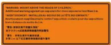
Mount above the heads of children. When within 1 m of the product, avoid eye exposure to avoid temporary or permanent eye damage.
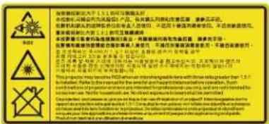
4K22-HS and 4K22A-HS may become RG3 when an interchangeable lens with throw ratio greater from 1.5-2.0:1 is installed.
4K13-HS and 4K13A-HS may become RG3 when an interchangeable lens with throw ratio greater from 2.0-4.0:1 is installed.
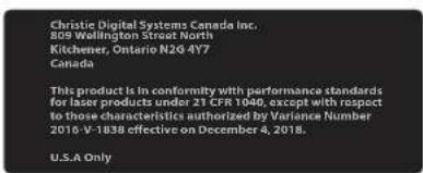
FDA laser variance (US projectors only).
This product is in conformity with performance standards for laser products under 21 CFR 1040, except with respect to those characteristics authorized by Variance Number 2016-V-1838 effective on December 4, 2018.
Additional safety hazard
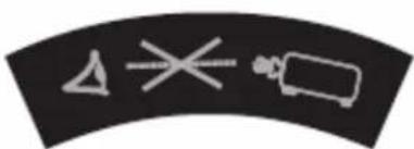
natural_image
Abstract curved line with three white geometric shapes on black background (no text or symbols)Do not look directly into the lens. The extremely high brightness can cause permanent eye damage.
Projector overview
The HS Series 4K is a high brightness, high-resolution video graphics one-chip laser-based projector. The projector is available in 4K resolution and uses Digital Light Processing (DLP™) technology from Texas Instruments. It is primarily designed for fixed installation and secondary applications including rental-staging and LBE (Location Based Entertainment). This product is used for professional applications and is not for domestic use.
Contact your dealer
Record the information about your projector and keep this information with your records to assist with the servicing of your projector. If you encounter a problem with your Christie projector, contact your dealer.
Purchase record
| Dealer: |
| Dealer or Christie Sales/Service contact phone number: |
| Projector serial number:The serial number can be found on the license label located on the display panel |
| Purchase date: |
| Installation date: |
Ethernet settings
| Default gateway | |
| Projector IP address | |
| Subnet mask |
Key features
• 4K 3840 x 2160 resolution
• High picture quality with superb brightness performance
- Lens suite options for installation flexibility
- Powered lens adjustment with lens memory function
- Projection lens compatibility:
• 360 degrees projection
• 3D blending and auto warping
• Supports fog filter as an optional accessory
• Full HD 3D technology with frame sequential up to 120 Hz
• Support 4K 3D dual pipe
• Support 1920 x 1080@240Hz
- Christie Twist™ and Mystique™ allows for easy and quick blending and warping. Support for Mystique™ camera based alignment system (sold separately)
- A wide range of connectivity including HDMI, HDBaseT, and 3D inputs
- Integrated HDBaseT solution supports 4K video streaming through RJ45
• SNMP traps and email notifications
• 10-bit image processor electronics with modular design
- All video formats can be resized to full screen either horizontally or vertically while maintaining aspect ratio.
• The projector can be operated using any of the following:
- The built-in keypad, the infrared (IR) remote keypad, a wired remote keypad, or a PC/device using serial communications (Ethernet or RS232)
- A web page using Ethernet, or from a PC or device using a wireless USB dongle (optional)
How the projector works
The HS Series 4K projectors accept a variety of input signals for a wide range of commercial projection applications.
Designed with solid-state illumination light sources and phosphor technology, the red, green and blue color elements are segmented through a phosphor wheel and modulated by one Digital Micromirror Device (DMD) panel responding to incoming data streams of digitized red, green, and blue color information. As these digital streams flow from the source, light from the responding on pixels of the DMD panel is reflected, converged, and projected to the screen through projection lenses, where all pixel reflections are superimposed in sharp full-color images.
List of components
This projector comes with all the items listed below. Check to make sure your package is complete. If anything is missing, contact your dealer.
- AC power cord
• I R rem o t e k e y p a d
• Product Safety Guide
Product documentation
For installation, setup, and user information, see the product documentation available on the Christie Digital Systems USA Inc. website at www.christiedigital.com. Read all instructions before using or servicing this product.
- Access the documentation from the Christie website:
- Go to this URL: http://bit.ly/2JtghsE or https://www.christiedigital.com/en-us/business/products/projectors/1-chip-dlp/hs-series
- Scan the QR code using a QR code reader app on a smartphone or tablet.

- On the product page, select the model and switch to the Downloads tab.
Related documentation
Additional information on the projector is available in the following documents.
• HS Series 4K Installation and Setup Guide (P/N: 020-002055-XX)
• HS Series 4K Product Safety Guide (P/N: 020-002052-XX)
• HS Series 4K Service Manual (P/N: 020-002054-XX)
• HS Series 4K Serial Commands Technical Reference (P/N: 020-103737-XX)
- Twist User Guide (P/N: 020-101380-XX)
- Mystique Operate Instruction Sheet (P/N: 020-102382-XX)
Technical support
Technical support for Christie Enterprise products is available at:
• North and South America: +1-800-221-8025 or Support.Americas@christiedigital.com
• Europe, Middle East, and Africa: +44 (0) 1189 778111 or Support.EMEA@christiedigital.com
• Asia Pacific (support.apac@christiedigital.com):
• Australia: +61 (0)7 3624 4888 or tech-Australia@christiedigital.com
• China: +86 10 6561 0240 or tech-supportChina@christiedigital.com
- India: +91 (80) 6708 9999 or tech-India@christiedigital.com
• Japan: 81-3-3599-7481
• Singapore: +65 6877-8737 or tech-Singapore@christiedigital.com
- South Korea: +82 2 702 1601 or tech-Korea@christiedigital.com
• Christie Professional Services: +1-800-550-3061 or NOC@christiedigital.com
Additional information
Lens type for 4K (4K22-HS, 4K22A-HS, 4K13-HS, 4K13A-HS).
| Lens type 140-142108-XX | 140-144100-XX | 140-115108-XX | 140-109101-XX | 140-110103-XX | 140-111104-XX | 140-116109-XX | 140-145101-XX | |
| Throw Ratio 0.38 | 0.65 - 0.75 1.02 - 1 | 1.36 1.2 - 1.5 1.5 - 2 | 0 2.0 - 4.0 4.0 - 7.2 | 7.2 - 10.8 | ||||
| Projection Lens | Ultra Short Throw | Short Throw | Wide Zoom | Wide Zoom | Standard | Long Zoom | Ultra-Long Zoom | Ultra-Long Throw |
| Zoom Ratio | No Zoom | 1.15X | 1.33X | 1.25X | 1.33X | 2X | 1.8X | 1.5X |
Installation and setup
Learn how to install, connect, and optimize the projector display.
Site requirements
To safely install and operate the projector, the installation location must have restricted access for authorized personnel only and meet these minimum requirements.
Physical operating environment
Provides specifications for the operating environment.
Item Specification
| Ambient temperature (operating) 0 to | 40°C (32 to 104°F) for 0 to 762 meters (0 to 2500 feet) |
| 0 to 35°C (32 to 95°F) for 762 to 1524 meters (2500 to 5000 feet) | |
| 0 to 30°C (32 to 86°F) for 1524 to 3048 meters (5000 to 10,000 feet) | |
| Storage temperature range -10 to 60°C (14 to 140°F) | |
| Humidity range 10% to 85% RH (maximum), non condensing | |
| Storage humidity range 5% to 90% RH (maximum), non condensing | |
| Operating altitude 3048 meters (10,000 feet) maximum | |
Power connection
The projector uses an AC power system allowing the projector to operate at full brightness with a power supply of 100 to 240 VAC. Operating the device outside of the voltage range may cause unsatisfactory operation or damage to the projector. To ensure safety operation, only use the AC power cord provided with the product or recommended by Christie.
Model name Power requirements
| 4K13-HS, 4K13A-HS • 100-240 VAC, | 50/60Hz, 11 A• 100-120 VAC, 50/60Hz, 11 A• 220-240 VAC, 50/60Hz, 5 A |
| 4K22-HS, 4K22A-HS • 100-240 VAC, | 50/60Hz, 13.5 A• 100-120 VAC, 50/60Hz, 13.5 A• 220-240 VAC, 50/60Hz, 8.5 A |
Projector components
Identify the main components of the projector.
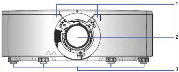
Front view
Identify the main components on the front of the projector.
ID Part name Description
| 1 | Front IR sensor | Receives signals from the IR remote keypad. Keep the signal path to the sensor unobstructed for uninterrupted communication with the projector. |
| 2 | Projection lens | Allows automated lens control and adjustment: vertical and horizontal offsets, zoom, and focus. |
| 3 Adjustable feet Raises or lowers the feet to level the projector. | ||
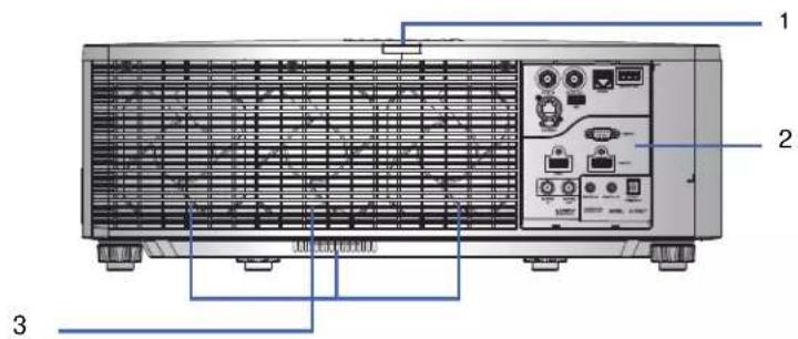
Rear view
Identify the main components on the rear of the projector.
ID Part name Description
| 1 Rear | IR sensor Receives signals from the IR remote keypad. Keep the signal path unobstructed for uninterrupted communication with the projector. |
| 2 Input/Output (I/O) panel Connects the projector to external devices. | |
| 3 Cooling air vents (exhaust) Provides cooling to the projector. Keep these vents unobstructed to prevent the projector from overheating. | |
Left view
Identify the main components on the left side of the projector.
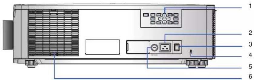
ID Part name Description
| 1 Built-in keypad Controls the projector. | |
| 2 AC input Connects to the supplied power adapter. | |
| 3 Power button Powers the projector on or off. | |
| 4 Kensington lock Secures the projector to counter tops, tables, and so on. | |
| 5 Fuse • 4K13-HS/4K13A-HS: T15A/250VAC• 4K22-HS/4K22A-HS: T20A/250VAC | |
| 6 Cooling air vents (intake) Provides cooling to the projector. Keep these vents unobstructed to prevent the projector from overheating. |
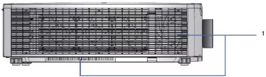
Right view
Identify the main component on the right side of the projector.
natural_image
Technical line drawing of a heat exchanger or cooling unit with internal grid structure and mounting base (no text or symbols)ID Part name Description
1 Cooling air vents (intake) Provides cooling to the projector. Keep these vents unobstructed to prevent the projector from overheating.
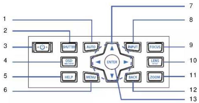
Built-in keypad
The built-in keypad controls the projector.
flowchart
graph TD
    A["1"] --> B["SHUTTER"]
    C["2"] --> B
    D["3"] --> E["OUTPUT"]
    F["4"] --> G["OXD WITHROOM"]
    H["5"] --> I["HELP"]
    J["6"] --> K["MENU"]
    L["7"] --> M["INPUT"]
    N["8"] --> O["FOCUS"]
    P["9"] --> Q["LENS WITH"]
    R["10"] --> S["ZOOM"]
    T["11"] --> U["BACK"]
    V["12"] --> W["ENTER"]
    X["13"] --> W
    style W fill:#f9f,stroke:#333,stroke-width:2px
ID Button Description
| 1 AUTO Automatically optimizes an image. | |
| 2 SHUTTER Displays or blanks the video image. | |
| 3 POWER Turns the projector on or off. | |
| 4 | OSD HIDE/SHOW Hides or shows the on-screen display (OSD) menus. |
| 5 HELP Displays the instructions for source connection. | |
| 6 | M E N U D i s p l a y s t h |
| 7 Arrow Keys Adjusts a setting up or down, or navigate within a menu. | |
| 8 | INPUT Selects an input for the main or picture in picture/picture by picture (PIP/PBP) image. |
| 9 FOCUS Adjusts the focus. | |
| 10 | LENS OFFSET Adjusts the lens vertical or horizontal offset setting. |
| 11 | ZOOM Adjusts the zoom. |
| 12 | BACK Returns to the previous level or exits the menus if at top level. |
| 13 | ENTER Confirms the item selection. |
Input/output (I/O) panel
Identify the components of the Input/Output (I/O) panel.
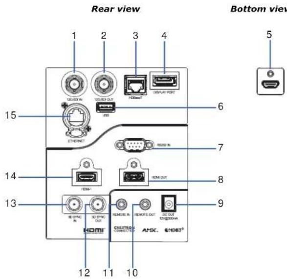
ID Connector name ID Connector name
| 1 12G-SDI IN 9 DC OUT | |||||||||||
| 2 12G-SDI OUT 10 REMOTE OUT | |||||||||||
| 3 HDBaseT 11 REMOTE IN | |||||||||||
| 4 DISPLAY PORT 12 3D SYNC OUT | |||||||||||
| 5 | H | D | M | I | - | 2 | 1 | 3 | 3 | D | S |
| 6 USB (5 V/500 mA) 14 HDMI-1 | |||||||||||
| 7 RS232 IN | 15 ETHERNET (10/100 Mbps) | ||||||||||
| 8 | H | D | M | I | O | U | T | ||||
Y N C I N
IR remote keypad
The IR remote keypad communicates with the projector by way of wireless communications.
If you choose to use a cable, not supplied, it must be 20 m (65.6 feet) or less. If the length of cable exceeds 20 m (65.6 feet), the IR remote keypad may not work correctly.
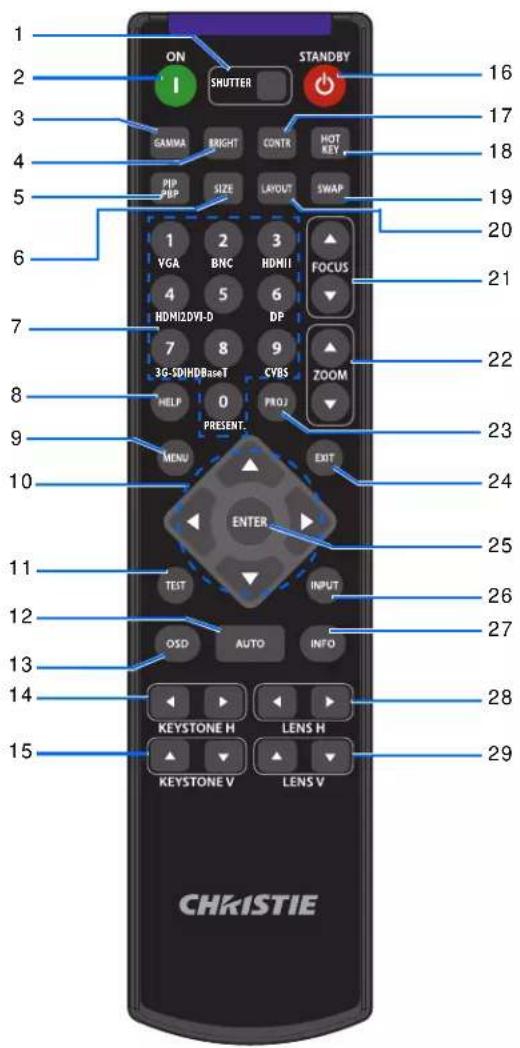
ID Button Description
| 1 SHUTTER Displays or blanks the video image. | |
| 2 ON Turns the projector on. | |
| 3 GAMMA Adjusts the mid-range levels. | |
| 4 BRIGHT Adjusts the amount of light in the image. |
| ID | Button Description | |
| 5 | PIP | Turns picture -in-picture/picture-by-picture (PIP/PBP) on or off. |
| PBP | ||
| 6 SIZE | Adjusts the PIP/PBP size. | |
| 7 | Number Keys | Enter a number, such as a channel, value, and so on. The on-screen display (OSD) indicates if a function is not supported. |
| 8 HELP | Displays the instructions for source connection. | |
| 9 | M E | N U D i s p l a y s t h |
| 10 Arrow Keys Adjusts a setting up or down to navigate within a menu. | ||
| 11 TEST Displays a test pattern. | ||
| 12 AUTO Automatically optimizes an image. | ||
| 13 OSD | Hides or shows OSD menus. | |
| 14 KEYSTONE H | Adjusts the horizontal keystone. | |
| 15 KEYSTONE V | Adjusts the vertical keystone. | |
| 16 STANDBY | Turns the projector off. | |
| 17 CONTR | Adjusts the difference between dark and light. | |
| 18 HOT KEY | Selects your preset key quickly. | |
| 19 SWAP | Swaps the main and PIP/PBP images. | |
| 20 LAYOUT | Adjusts the PIP/PBP layout. | |
| 21 FOCUS | Adjusts the focus to improve image clarity as required. | |
| 22 ZOOM | Adjusts the zoom to achieve a required image size. | |
| 23 PROJ Changes the IR remote keypad ID. | ||
| 24 EXIT | Returns to the previous level or exits menus if at the top level. | |
| 25 | ENTER | Selects a highlighted menu item, or changes or accepts a value. |
| 26 INPUT | Selects an input for the main or PIP/PBP image. | |
| 27 INFO Displays the projector information. | ||
| 28 LENS H | Adjusts the position of the image horizontally. | |
| 29 LENS V | Adjusts the position of the image vertically. | |
Positioning the display
When you select a position for the projector, consider the size and shape of your screen, the location of your power outlets, and the distance between the projector and the rest of your equipment. Follow these general guidelines:
- Position the projector on a flat surface at a right angle to the screen. The projector (with the standard lens) must be at least 1.6 m (5.2 feet) from the projection screen.
- Position the projector to the required distance from the screen. The distance from the lens of the projector to the screen, the zoom setting, and the video format determine the size of the projected image.
- Determine the lens throw ratio.
For more information detailing the throw ratio for each lens, refer to the HS Series 4K Lens Throw Ratios Technical Reference (P/N: 020-103738-XX).
• 360 degree free orientation operation
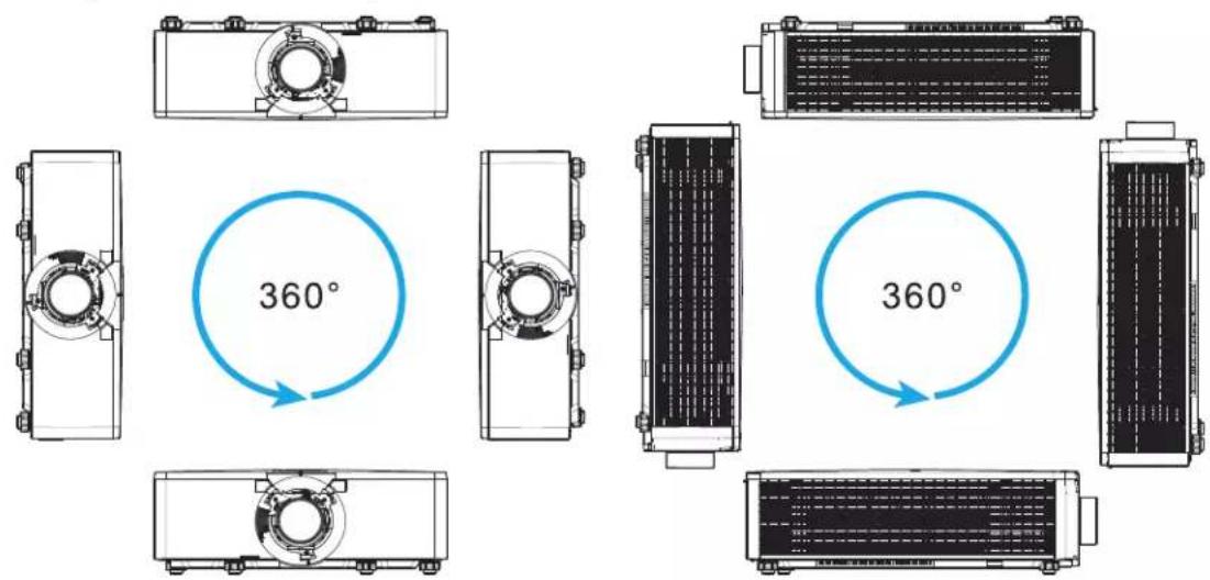

When installing the projector in portrait orientation, Christie recommends the built in keypad and power inputs face upwards. This allows access to the built in keypad and power connections during operation.
Turning on the projector
The projector cables must be securely connected before turning the power on.

Warning! Failure to comply with the following could result in death or serious injury.
- Do not look into the projector lens when the laser is on. The bright light may result in permanent eye damage.
-
Installing or replacing a lens must be done by a Christie-qualified service technician to avoid exposure to dangerous emission levels.
-
Plug the projector in to AC power.
The Power button on the built in keypad is illuminated when the power cables are connected.
- Ensure the lens has been installed in the projector by a Christie-qualified service technician.
- Ensure no one or no objects are in the beam path before turning on the projector.
- To turn on the projector, on the IR remote keypad on the built-in keypad select ⏻
The status LED is green with a long blink.
- To select an input source and turn it on, on the IR remote keypad select INPUT.
Available input sources are HDMI1, HDMI2, Display Port, 12G-SDI, and HDBaseT.
The projector detects the source you selected and displays the image.
- If using the projector for the first time, select a preferred language from the Main Menu after the startup screen is displayed.
Turning off the projector
Power off the projector in preparation for inspection or maintenance.
- To turn the projector off, on the IR remote keypad or built-in keypad select
A warning message appears on the displayed image.
- To confirm your selection, select again.
If you do not select again, the warning message disappears after three seconds and the projector remains on.
LED status indicator
LED status indicator helps identify the projector state. LEDs are defined below.
Status LED
Identify the LED state colors and meaning.
LED status Projector state
| Off AC power is off (without AC plugged in). | |
| Green (flashing) Projector is starting up. | |
| Green (solid) System is operating normally. | |
| Blue (flashing) Projector is cooling down. | |
| Blue (solid) Projector is in standby mode. | |
| Yellow (flashing) A problem exists with the projector that does not cause it to shut down.Examples of warnings include: filter needs changing, one of the pumps is damaged, or a fan is operating at full speed due to over temperature of laser diode (LD) driver. | |
| Yellow (solid) The end user is turning off the projector while it is in a warning state. | |
| Red (flashing) An error with the projector exists causing it to shut down.Examples of errors include: fan failure, over temperature, wrongly installed filter, or color wheel (CW) failure. | |
| Red (solid) The user is turning off the projector while it is in an error state. | |
| White (flashing) | Projector is in Firmware Upgrade Mode. |
Shutter LED
Identify the shutter LED state colors and meaning.
LED status Projector state
| Off Projector is on and Magenta (solid) | an image is displayed. Shutter is open. |
| Projector is on and the image is blank. Shutter is closed. |
Adjusting the size and position
Adjust the projector's size and position. Christie recommends warming the lens before completing these procedures as focus may change as the lens warms.
Setting the image size preset
Set the image size preset to display the image in its native resolution or to resize by maximizing the height, width, both height and width, or to the maximum size while keeping the original aspect ratio.
-
Select Menu > Size & Position > Size Presets.
-
Select the appropriate size preset:
• Auto—Displays with the detected size.
- Native—Displays in its native resolution.
• 4:3—Retains 4:3 aspect ratio.
- Letterbox—Makes the active content enlarge to the full screen.
• Full Size—Fills the screen, regardless of the source.
• Full Width—Fills display width and keep aspect ratio.
• Full Height—Fills display height and keep aspect ratio.
- Custom—Stretches the display horizontally and vertically without cutting the image display.
• 3D Mode—Displays 3D content. All other items are grayed out, if 3D Mode is selected.
- To confirm the selection, select ENTER.
Setting the digital size of display image
These functions are similar technologies as in-camera image processing. Use Digital Horz Zoom or Digital Vert Zoom to enlarge or to compress the display image horizontally or vertically.
- Select Menu > Size & Position > Digital Horz Zoom or Digital Vert Zoom.
- Adjust the slider by arrow keys or select ENTER to input the value you selected.
- After inputting the value, select ENTER to apply.
Setting the digital position of display image
Change the position of the projector's display image horizontally or vertically.

Digital Horz Shift is only available after adjusting the Digital Horz Zoom, and Digital Vert Shift is only available after adjusting the Digital Vert Zoom.
- Select Menu > Size & Position > Digital Horz Shift or Digital Vert Shift.
- Adjust the slider by arrow keys or select ENTER to input the value you selected.
- After inputting the value, select ENTER to apply.
Geometry correction
Modify the geometry of the display image directly on the projector.
Connecting to Christie Twist and Mystique grays out the geometry correction settings on the projector. Uploading warp and blend from Twist and Mystique overwrites the currently applied geometry correction settings. See Configuring warp and blend on page 34 for more details.
Enabling geometry correction
Enable or disable the geometry correction function including Warp, Blend, Keystone, Pincushion, 4-Corner, Auto Warp Filter, and Manual Warp Filter.
- Select Menu > Size & Position > Geometry Correction > Geometry Enable.
- To enable the setting, select ENTER.
Saving geometry correction
Save the warp and blend settings to the projector memory. The blend memory saves the edge blend settings, while the warp memory saves the settings of Keystone, Pincushion, 4-Corner, Manual Warp Filter, and image warp.
- Select Menu > Size & Position > Geometry Correction > Warp Memory > Save Warp or Blend Memory > Save Blend.
- To save the geometry setting, select a record.
One projector can save up to four warps and four blends. - To confirm the selection, select ENTER.
Applying geometry correction
Apply the previously saved geometry setting to the projector.
- Before applying the previous geometry setting, save the geometry setting to the projector.
See Saving geometry correction on page 29 for further information. - Select Menu > Size & Position > Geometry Correction > Warp Memory > Apply Warp or Blend Memory > Apply Blend.
- To apply the specific geometry setting, select the required record.
- To confirm the selection, select ENTER.
- To erase the applied geometry setting, select Off.
Enabling basic image blending
Configure blends directly on the projector to increase or decrease the borders of an individual image, so it blends with a neighboring image to create a single, seamless image.
You can set blends on a projector when not using Christie Twist and Mystique. Connecting to Twist and Mystique grays out the blend settings on the projector. Applying blends from Twist and Mystique overwrites the blends directly set on the projectors.
- Select Menu > Size & Position > Geometry Correction > Blend Area.
- Choose a side to blend in with the other projectors.
- To set up the starting position, select Start Pixel.
- Adjust the slider by arrow keys or select ENTER to input the starting position.
- After inputting the starting position, select ENTER.
- To set up the size of blend area, select Pixel Height.
- Adjust the slider by arrow keys or select ENTER to input the width of blend area.
- After inputting the size of blend area, select ENTER.
- To set the gamma value of the blend area, select Blend Gamma.
- After selecting a gamma value, select ENTER.
- To apply the settings, select Enable.
- Select ENTER.
- To save the blend setting, select Menu > Size & Position > Geometry Correction > Blend Memory > Save Blend.
- To set up the other side of blend area, repeat step 2 to 13.
Blending multiple images
Use Christie Twist to manually configure edge blends and apply them to the projectors.
Christie Twist Premium and Twist Pro offer advanced blending options. Refer to the Christie website (www.christiedigital.com) for product information and documentation.
- Connect the projector and computer to the same network and subnet.
- To add a projector to a computer, from the Twist menu, select Home > Add.
- To manually connect the projector with Twist, use port 3003.
- Connecting to Twist grays out the Geometry Correction settings on the projector.
- To manually connect the projector with Twist, use port 3003.
-
Connecting to Twist grays out the Geometry Correction settings on the projector.
-
Select a record number to save the blend setting.
You can save up to four blend settings.
- In Twist, configure edge blend settings.
Use the test patterns in Twist to assist in adjusting the blend area.
For more information about creating blend files in Twist, refer to Twist User Guide (P/N: 020-101380-XX).
-
To send the blend settings to the projector, on the canvas, right-click a projector window and select Send Blend.
-
Repeat step 2 to 5 for the remaining projectors.
For multiple projectors, use Twist to identify the projectors.
- To save the warp file on the projector, select File > Save or Save As.
When removing the projector from Twist, or closing the program, the projector automatically saves the currently applied blend settings to its blend memory.
- To change the name when saving blends on the projector, or update the memory location of the blend, select Properties.
The changed name shows on both Twist and the projector.
Downloading a blend from the projector memory
Use Twist to download the blend file saved on the projector memory.
- Before downloading the previous blend file, save the blend setting to the projector memory.
- On the canvas, click a projector window.
- Select File > Blend/Mask/B.U.
- In the Download Blend dialog, select the required record.
- To download the selected blend setting, select OK.
- To apply the blend setting to the projector, on the canvas, right-click a projector window and select Send Blend.
Adjusting horizontal keystone
Use horizontal keystone to correct a keystoned image shape in which the left and right borders of the image are unequal in length, and the top and bottom are slanted to one of the sides.
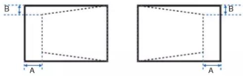
- Select Menu > Size & Position > Geometry Correction > Keystone > Horz Keystone.
- To adjust the horizontal keystone, adjust the slider by arrow keys or select ENTER to input the value you selected.
- After inputting the value, select ENTER to apply.
Adjusting the vertical keystone
Use vertical keystone to correct a keystoned image shape in which the top and bottom borders of the image are unequal in length, and both sides of the image are inclined toward the top or bottom edge.
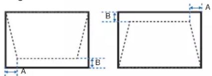
- Select Menu > Size & Position > Geometry Correction > Keystone > Vert Keystone.
- To adjust the vertical keystone, adjust the slider by arrow keys or select ENTER to input the value you selected.
- After inputting the value, select ENTER to apply.
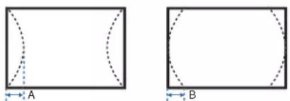
Adjusting horizontal pincushion
Use horizontal pincushion to correct a pinched image shape in which the horizontal straight lines are curved inwards or horizontal straight lines are curved outwards from the center.
natural_image
Two geometric diagrams showing a rectangle with dashed curved lines and labeled dimensions A and B (no text or symbols beyond labels)- Select Menu > Size & Position > Geometry Correction > Pincushion > Horz Pincushion.
- To adjust the horizontal pincushion, adjust the slider by arrow keys or select ENTER to input the value you selected.
- After inputting the value, select ENTER to apply.
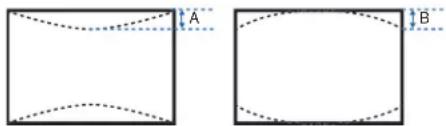
Adjusting vertical pincushion
Use vertical pincushion to correct a pinched image shape in which the vertical straight lines are curved inwards or vertical straight lines are curved outwards from the center.
natural_image
Two geometric diagrams showing a rectangle with dashed and solid lines, labeled A and B (no text or symbols within the shapes)- Select Menu > Size & Position > Geometry Correction > Pincushion > Vert Pincushion.
- To adjust the vertical pincushion, adjust the slider by arrow keys or select ENTER to input the value you selected.
- After inputting the value, select ENTER to apply.
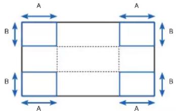
Adjusting 4-corner
Use 4-corner to correct the four corners of the projector's display image.
- Select Menu > Size & Position > Geometry Correction > 4-Corner.
- Select the corner and the direction to adjust.
- To move the corner, adjust the slider by arrow keys or select ENTER to input the value.
- After inputting the value, select ENTER to apply.
- To adjust the other corner or direction, repeat step 2 to 4.
Enabling auto warp filter
Improve the sharpness of the image and reduce the ghosting automatically after geometry correction, such as keystone, pincushion, 4-corner, and warping.
- Select Menu > Size & Position > Geometry Correction > Auto Warp Filter.
- To enable the setting, select ENTER.
Adjusting warp filter
Improve the sharpness of the image after geometry correction, such as keystone, pincushion, 4-corner, and warping. Adjust the warp filter manually to reduce the ghosting.
- Select Menu > Size & Position > Geometry Correction > Manual Warp Filter.
- To reduce the ghosting in different direction, select Horz Filter or Vert Filter.
- Adjust the slider by arrow keys or select ENTER to input the value.
- After inputting the value, select ENTER to apply.
Resetting geometry correction setting
Reset all geometry correction parameters back to default, including warp and blend settings.
- Select Menu > Size & Position > Geometry Correction > Reset to Default.
- Select ENTER.
Configuring warp and blend
By blending multiple images, you can combine several projectors to create a larger and seamless image. When the projection screen is not perfectly flat or rotated at an angle, warp the image to fit on the irregular surface.
Warping an image
Christie Twist offer various manual warping options to adjust the image shape with minimal performance impact. Refer to the Christie website (www.christiedigital.com) for product information and documentation.

Christie Twist can be upgraded to Twist Premium and Twist Pro that provides more advanced warping features. Refer to the Christie website (www.christiedigital.com) for product information and documentation.
- Connect the projector and computer to the same network and subnet.
- To add a projector to a computer, from the Twist menu, select Home > Add.
- To manually connect the projector with Twist, use port 3003.
-
Connecting to Twist grays out the Geometry Correction settings on the projector.
-
Select a record number to save the warp.
You can save up to four warp settings.
- In Twist, configure warp settings.
Use the test patterns in Twist to help with image shaping.
For more information about creating warp files in Twist, refer to Twist User Guide (P/N: 020-101380-XX).
-
To send the warp settings to the projector, on the canvas, right-click a projector window and select Send Warp.
-
To save the warp settings on the projector, select File > Save or Save As.
When removing the projector from Twist, or closing the program, the projector automatically saves the currently applied warp settings to its warp memory.
- To change the name when saving warps on the projector, or update the memory location of the warp, select Properties.
The changed name shows on both Twist and the projector.
Downloading a warp from the projector memory
Use Twist to download the warp file saved on the projector memory.
- Before downloading the previous warp file, save the warp setting to the projector memory.
- On the canvas, click a projector window.
- Select File > Warp.
- In the Download from Memory Location list, select the required record.
- To download the selected warp setting, select OK.
- To apply the warp setting to the projector, on the canvas, right-click a projector window and select Send Warp.
Performing auto warp and blend
Use Mystique (sold separately) to perform automatic warp, blend, and more advanced geometry settings. Mystique is an automated camera-based alignment and recalibration solution that lets you quickly stage, install, align, calibrate, and maintain multi-projection systems.
Refer to the Christie website (www.christiedigital.com) for product information and documentation.
Adjusting the image settings
Learn how to adjust the projector image.
Adjusting the brightness
Adjust the intensity of the image.
- Select Menu > Image Settings > Brightness.
- Adjust the slider by arrow keys or select ENTER to input the value.
- After inputting the value, select ENTER to apply.
Adjusting the contrast
Adjust the degree of difference between the lightest and darkest parts of the image and changes the amount of black and white in the image.
- Select Menu > Image Settings > Contrast.
- Adjust the slider by arrow keys or select ENTER to input the value.
- After inputting the value, select ENTER to apply.
Adjusting the color space
Determine how the color components are decoded for accurate color in the display.
- Select Menu > Image Settings > Color Space.
- If projector does not detect the correct input signal while Auto is enabled, disable Auto by selecting ENTER to select color space manually.
- To match up with the input signal, select appropriate color space:
- A u t o - RGB
- R G B F u l l
- R G B L i m i t e d
- YUV
- R E C 7 0 9
- R E C 6 0 1
- To confirm the selection, select ENTER.
Adjusting the image sharpness
Adjust the edge clarity of the image.
- Select Menu > Image Settings > Detail.
- Select the sharpness:
• M a x i m u m
- High
- Normal
- To confirm the selection, select ENTER.
Setting up 3D display
Use the functions in 3D Display menu to make the timing adjustment and environment necessary for displaying 3D images.
Setting 3D mode
Set up the 3D mode according to the 3D input signal.
- Select Menu > Image Settings > 3D Display > 3D Mode.
-
Select the appropriate 3D mode:
-
Active 3D
-
Passive 3D
-
To confirm the selection, select ENTER.
Setting 3D format
Set up the 3D format according to the 3D input signal.

- Projecting the image in 4K 3D/4K 3D Dual Pipe format may display a few jitter effects. This is considered as a normal behavior.
- 4K 3D Dual Pipe has limited warping options when processing image distortion correction such as keystone and pincushion.
-
4K 3D/4K 3D Dual Pipe format is supported only with HDMI 1 and HDMI 2 sources.
-
Select Menu > Image Settings > 3D Display > 3D Enable.
- Select the appropriate 3D format:
• Auto
- Frame Packing
- Side by Side
- Top and Bottom
- Frame Sequential
- Dual Pipe
• 4 K 3 D
- 4K 3D Dual Pipe
- Off
- To confirm the selection, select ENTER.
Inverting 3D signal
3D images consist of a series of images (frames) that alternate quickly between two slightly different view points, corresponding to our left and right eyes. When these frames are displayed fast enough and viewed with 3D glasses synchronized to the left/right (L/R) changes, the resulting image appears with the same depth and perspective that is sensed in the real world.
If the projector generates the sync internally and content is displayed without 3D sync in the cable connected to the projector, the content has a 50% chance of being displayed with the left/right eyes swapped. This function is used for swapping the sequence of the image to make the resulting image appear normally.
- Select Menu > Image Settings > 3D Display > 3D Invert.
- To swap, select ENTER.
Selecting the 3D sync input signal
This function is used for selecting the 3D sync input option.
- Select Menu > Image Settings > 3D Display > 3D Sync In Select.
- Select the appropriate 3D sync in setting.
- Auto—If an external 3D sync input is detected, the projector uses automatically the external sync input. If no external sync input is detected, the projector uses the internal 3D sync to display the content.
For multi-threaded applications, if the 3D enable function is set to Frame Sequential, Christie recommends to connect the source device to the projector using 3D Sync In port. The Frame Delay function makes sure a synchronized display for multiple projectors.
- Internal—The projector generates the 3D sync internally and content is displayed.
-
External—The projector uses an external 3D sync input to display the content.
-
To confirm the selection, select ENTER.
Setting the 3D sync output signal
This function is used for controlling and processing the 3D sync output signal.
- Select Menu > Image Settings > 3D Display > 3D Sync Out.
-
Select the appropriate 3D sync out setting.
-
To Emitter—If the 3D sync out port is connected to an emitter, select To Emitter to transmit 3D signal to emitter and give to 3D glasses.
-
To Next Projector—Multiple projectors 3D application only. Select To Next Projector when the 3D sync out port is not connected to an emitter.
-
To confirm the selection, select ENTER.
Setting the frame delay
Adjust the frame delay output through the projector.
It will introduce some delay, typically used in multi-machine synchronization for delay alignment.
- Select Menu > Image Settings > 3D Display > Frame Delay.
- Adjust the slider by arrow keys or select ENTER to input the value.
- After inputting the value, select ENTER to apply.
Setting the sync delay
Adjust the sync delay which eliminates the odd colors and cross talk caused by timing difference. Sync delay is the time difference between the first 3D signal being given and the result being executed from the current projector.
- Select Menu > Image Settings > 3D Display > Sync Delay.
- Adjust the slider by arrow keys or select ENTER to input the value.
- After inputting the value, select ENTER to apply.
Configuring the video settings
Configure the video settings to optimize the image performance, such as applying color to black and white videos, reducing luminance component noise, and so on.
Adjusting black and white video
Adjust a video image from black and white to fully saturated color. This feature is for video sources only.
- Select Menu > Image Settings > Video Options > Color.
- Adjust the slider by arrow keys or select ENTER to input the value.
- After inputting the value, select ENTER to apply.
Adjusting the color balance
Adjust the red-green color balance in NTSC video images. NTSC, named after the National Television System Committee, is the analog video color system used in North America and most of the South America countries. This feature is for NTSC video sources only.
- Select Menu > Image Settings > Video Options > Tint.
- Adjust the slider by arrow keys or select ENTER to input the value.
- After inputting the value, select ENTER to apply.
Configuring picture settings
Depending on display content, choose the most suitable picture settings. Different picture settings have different color temperature, brightness, and so on.
- Select Menu > Image Settings > Picture Settings.
-
Select the appropriate picture setting:
-
Video—Used for theater application. It sets the color temperature to 6000K with 70% of maximum brightness.
- Bright—Used for large size or high brightness application. It sets the color temperature to 7500K with 100% brightness.
- Enhanced—Used for images with richly saturated and vivid color. It is based on brightness mode.
- REC709—Used for high-definition television. It sets the color temperature to 6500K with 80% of the maximum brightness.
- DICOM SIM—Used for high contrast content, such as X-ray diagram. It sets the color temperature to 7500K with 65% brightness.
- Blending—Used for multiple projector application. It sets the color temperature to 7000K with 85% of maximum brightness.
- HDR—Used for displaying high dynamic range content for deepest blacks, brightest whites, and vivid cinematic color using REC.2020 color gamut.
- 3D—Used to display the 3D content. For more information on configuring 3D settings, see Setting up 3D display on page 37.
• High Frame Rate—Used for displaying 2D input signal at 240Hz. -
User—Customized picture setting. See Editing customized picture setting on page 41 for further details of creating a customized picture setting.
-
Select ENTER.
Applying customized user configuration setting
Apply the previously saved user customized picture setting to the projector.
- Before applying the customized picture setting, adjust the picture setting and save it using Menu > Image Settings > Picture Settings > User option.
-
Select Menu > Image Settings > Apply to User.
-
User Video
- User Bright
- User Enhanced
- User REC709
• User DICOMSIM - User Blending
• User HDR
• User 3 D -
User High Frame Rate
-
To apply the specific picture setting, select the required setting.
-
To confirm the selection, select ENTER.
Editing customized picture setting
Edit the previously saved customized picture setting.
- Select Menu > Image Settings > User configuration.
-
Select the customized image setting you want to modify:
-
User - Video
- User - Bright
- User-Enhanced
- User-REC709
• User - DICOMSIM - User - Blending
• User - HDR
• U s e r - 3 D -
User - High Frame Rate
-
Select ENTER.
Setting the contrast ratio
Use contrast enhancement function to raise the contrast ratio.
- Select Menu > Image Settings > Contrast Enhancement.
-
Select the appropriate calculation method for contrast ratio:
-
Dynamic Black ^TM —Adjusts the contrast ratio depending on the contents by minimizing the black levels in the projected image while electronically increasing the gain in the image. The result is enhanced detail and increased contrast ratio of 6500:1.
- Speed—Adjusts the speed of the light source correction. The value ranges from 1 to 15. A lower value makes the correction slower and less aggressive while a higher value results in the faster correction.
- Strength—Sets the strength of the dynamic contrast adjustment. The value ranges from 0 to 3, the higher the value the stronger the correction.
- Level—Adjusts the light source when the brightness level of the current content gets lower than the set value. The value ranges from 50 to 100, indicating 50% to 100% of the constant brightness. The higher the value, the larger the range to adjust the light source.
• Real Black—Turns off the laser light while projecting black content. - Lights Out Timer—Sets a timer for the laser light to turn off after detecting black content.
- Lights Out Signal Level—Sets a black level value as the threshold for the Real Black function. The value can be selected from 0 to 255, with 0 being the darkest black and 255 being the brightest.
- Lights On Threshold—Sets the lights on value to eliminate the Real Black effect. The function is activated when the screen brightness is higher than the value of both the Lights On Threshold and the Lights Out Signal Level. The Lights on Threshold value ranges from 0 to 127.
-
Reset to Default—Resets all contract enhancement settings to the default factory defaults.
-
To confirm the selection, select ENTER.
Enabling the image freeze
Pause the display screen despite any change in the source device.
- Select Menu > Image Settings > Image Freeze.
- To pause the screen, select Image Freeze.
- To unfreeze the screen, select any button on the keypad or remote control.
- Select Yes.
Setting the high dynamic range
High dynamic range (HDR) is set to increase the dynamic range which allows the full spectrum of the image to be seen. HDR significantly expands the range of contrast ratio and color to show a more realistic and natural image. After enabling this function, you can see details in the dark, at the same time, the bright part of the image is still visible.

- The HDR function only works when the projector is receiving signal from the HDMI input. You must set Picture Settings to Bright.
-
Enabling HDR disables the picture-in-picture/picture-by-picture (PIP/PBP) function.
-
Select Menu > Image Settings > HDR.
-
Select appropriate setting for HDR:
• Auto—Auto detect HDR content.
- Level—Select an appropriate HDR effect.
- HDR1—Low HDR effect, used for bright images to increase the color saturation.
-
HDR2—Medium HDR effect, used for standard images to make them look more realistic and natural.
• HDR3—Medium HDR effect, used for video content to improve image details.
• HDR4—Strong HDR effect, used to improve image details in dark scenes. -
To confirm the selection, select ENTER.
Adjust the color of the image
Calibrate the accuracy of primary colors and the wall color, which can change because of lighting and environmental factors. Lighting and other environmental factors may slightly change how these colors appear on your screen. While the change is negligible in most cases, you may prefer to recover the originally intended color performance before trying to match colors from several projectors.
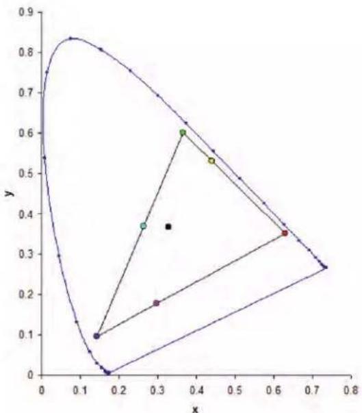
Adjusting primary colors
To achieve consistency use a color meter to measure the native primary colors-red, green, blue, and white, as they appear on the screen. Use hue, saturation and gain (HSG) to adjust each color component to essentially calibrate a projector to its surroundings, compensating for factors such as screen type, lamp and/or ambient lighting, and improves color accuracy and consistency in a group of projectors. It ensures a good starting point for further customizing and matching; however, is not critical for all installations.
line
| x | y | | ---- | ----- | | 0.15 | 0.10 | | 0.25 | 0.38 | | 0.35 | 0.60 | | 0.45 | 0.53 | | 0.65 | 0.35 |- Select Menu > Image Settings > Color Matching > HSG Adjustment.
- To view a specific color while adjusting, select ENTER to enable Auto Test Pattern.
- Select one primary color (red, green, blue, cyan, magenta, or yellow).
- To edit hue of the primary color, adjust the slider or enter the color values of the primary color component you selected until satisfied with the colors.
Hue values reflect the number of degrees of rotation around the wheel from the original color of the pixel. Increasing the value indicates counterclockwise rotation and decreasing the value indicates clockwise rotation.
- To confirm the selection, select ENTER.
- To edit saturation of the primary color, adjust the slider or enter the color values of the primary color component you selected until satisfied with the colors.
Saturation values reflect the color shifting away from the primary color or toward white.
- To confirm the selection, select ENTER.
- To edit gain of the primary, adjust the slider or enter the color values of the primary color component you selected until satisfied with the colors.
Increasing value indicates increasing the lightness, and decreasing the value indicates decreasing it to black.
- To confirm your selection, select ENTER.
- Repeat steps 3 to 9 for each primary color component, except white.
- To edit the color of white by three components—red, blue and green—adjust the slider or enter the values until you are satisfied with the white.
- To confirm your selection, select ENTER.
- To reset the primary colors to their defaults, select Reset to Default.
- To reset back to default setting, select ENTER.
Setting the wall color
Set the wall color so the projector can enhance the color performance customized for the specific wall.
- Select Menu > Image Settings > Color Matching > Wall Color.
-
Select the preferred setting:
-
White
• G r a y 1 3 0 -
Light Yellow
-
Select ENTER.
Setting the wall color automatically
Set the wall color automatically so the projector can enhance the color performance customized for the specific wall.

- Auto wall color option is disabled and grayed out if the picture mode is set to 3D or High Frame Rate with the current source or change to no source status. (The camera does not support 1x color wheel speed.)
-
Auto wall color option is also disabled and grayed out if the camera is not detected.
-
Select Menu > Image Settings > Color Matching > Auto Wall Color.
-
Select ENTER.
Adjusting the image settings automatically
Adjust various image settings automatically, including focus, wall color, and color uniformity.
Adjusting the image with automatic focus
Adjust the image focus automatically with camera kit.
- Display an image or test pattern that can be used to analyze image focus.
- Select Menu > Image Settings > Auto Image Settings > Auto Focus.
3. Select ENTER.

- Auto focus option is disabled and grayed out if the picture mode is set to 3D or High Frame Rate with the current source or change to no source status. (The camera does not support 1x color wheel speed.)
- Auto focus option is also disabled and grayed out if the camera is not detected or lens lock option is enabled.
Setting the wall color automatically
Set the wall color automatically so the projector can enhance the color performance customized for the specific wall.

- Auto wall color option is disabled and grayed out if the picture mode is set to 3D or High Frame Rate with the current source or change to no source status. (The camera does not support 1x color wheel speed.)
-
Auto wall color option is also disabled and grayed out if the camera is not detected.
-
Select Menu > Image Settings > Auto Image Settings > Auto Wall Color.
- Select ENTER.
Balancing the image color automatically
Balance the image color automatically with auto color uniformity.

- Image color calibration option is disabled and grayed out if the auto color uniformity option is disabled/unchecked and the picture mode is set to 3D or High Frame Rate with the current source or change to no source status. (The camera does not support 1x color wheel speed.)
-
Target selection and reset options are disabled and grayed out if the auto color uniformity option is disabled/unchecked.
-
Select Menu > Image Settings > Auto Image Settings > Auto Color Uniformity.
- Select appropriate option for image color uniformity:
- Enable—Enables or disables the auto color uniformity function.
- Calibration—Starts adjusting the image color.
- Target Selection—Selects a calibration target.
- Reset—Restores factory settings.
- Select ENTER.
Adjusting advanced image settings
Adjust the color value based on gamma, white peaking, color temperature, and save user settings for data recovery.
Adjusting the color value based on gamma setting
Adjust the color values to give a more detailed displayed image.
- Select Menu > Image Settings > Advanced Image Settings > Gamma.
- Select appropriate option:
• Video
- Film
- B r i g h t
- CRT
• D I C O M
- HDR—Only available if the picture mode is set to HDR.
- Select ENTER.
Adjusting the white peaking
Use white peaking to adjust the color of white. The maximum value of white peaking, 100, can increase the brightness of white to near 100%.
- Select Menu > Image Settings > Advanced Image Settings > White Peaking.
- Adjust the slider by arrow keys or select ENTER to input the value.
- Select ENTER.
Adjusting the color temperature
Adjust the color temperature as expressed in degrees Kelvin.
- Select Menu > Image Settings > Advanced Image Settings > Color Temperature.
-
Select appropriate color temperature:
-
Warmest—Sets the color temperature to 5500K.
- Warm—Sets the color temperature to 6500K.
-
Cool—Sets the color temperature to 7500K.
-
Select ENTER.
Saving user settings for data recovery
Create a recovery copy of all the user data. This information can be used later to recover settings if necessary.
- Select Menu > Image Settings > Advanced Image Settings > Backup Restore > Save.
- To save the user data, select an empty record.
One projector can save up to five backups.
- To confirm the selection, select ENTER.
- Select Menu > Image Settings > Advanced Image Settings > Backup Restore > Restore.
- To restore a specific backup, select the required record.
- To start restoring data, select ENTER.

- The recovery copy does not include information about the source and functions that can be operated directly from the remote control and do not save the value after the next power on. For example, Image Freeze.
-
All other function values are saved to the recovery copy, except for the following:
-
Configuration > Lens Settings
- Configuration > Communications > LAN/WLAN
- Size & Position > Geometry Correction
- Configuration > Menu Preferences > PIN Protect
- Configuration > Date and Time
- Configuration > Schedule
Configuring system settings
Learn how to configure the system settings.
Changing the language
Choose the language you want displayed on projector display panel and on-screen display.
- Select Menu > Configuration > Language.
You can also select Menu > Language.
-
Select the appropriate language.
-
Select ENTER.
Adjusting lens settings
Adjust various lens settings including focus, zoom, lens position, memorizing lens position and locking the lens motors.
Viewing the lens type
View the projector lens type:
- Undefined Lens
- TR 0.65 -0.75
- TR 1.02 - 1.36
• TR 1.2 - 1.5
- TR 1.5 - 2.0
- TR 2.0 - 4.0
- TR 4.0 - 7.2
- TR 7.2 - 10.8
• TR 0.38
Aligning the image with focus, zoom, and auto focus
Adjust the image focus automatically with camera kit.
- Adjust the image focus automatically with camera kit.
- Select FOCUS on keypad or remote control.
You can also select Menu > Configuration > Lens Settings > Focus.
- Use the up and down arrow keys to adjust the focus of the image.
- To exit the menu, select EXIT.
- To adjust the focus automatically, select Menu > Configuration > Lens Settings > Auto Focus.
- Select ENTER.
- Select ZOOM on keypad or remote control.
You can also select Menu > Configuration > Lens Settings > Zoom.
- Use the up and down arrow keys to zoom in or out of the image.
- To exit the menu, select EXIT.
- To refine your adjusts, repeat steps 2 to 7.
Adjusting the image with automatic focus
Adjust the image focus automatically with camera kit.

- Auto focus option is disabled and grayed out if the picture mode is set to 3D or High Frame Rate with the current source or change to no source status. (The camera does not support 1x color wheel speed).
-
Auto focus option is also disabled and grayed out if the camera is not detected or lens lock option is enabled.
-
Display an image or test pattern that can be used to analyze image focus.
- Select Menu > Configuration > Lens Settings > Auto Focus.
- Select ENTER.
Adjusting lens position
Shift the lens to the specific position.
- Display an image or test pattern that can be used to analyze image location.
- Select LENS on keypad or LENS H/LENS V on remote control.
You can also select Menu > Configuration > Lens Settings > Lens Shift.
- Use the arrow keys to adjust the lens position.
- To exit the menu, select EXIT.
Saving lens setting
Save the lens position. One projector can save maximum up to five lens settings.
- Select Menu > Configuration > Lens Settings > Lens Shift Memory > Save Current Settings.
- To save the lens setting, select an empty record.
- To confirm the selection, select ENTER.
Applying the previous lens setting
Apply the previously saved lens setting to the projector.
- Before applying the previous lens setting, you need to save the lens setting.
See Saving lens setting on page 51 for further details. - Select Menu > Configuration > Lens Settings > Lens Shift Memory > Apply Position.
- To apply specific lens setting, select the required record.
- To confirm the selection, select ENTER.
Locking the lens motor
Prevent all lens motors from moving. It disables the zoom, focus, and offset settings, locking out any changes and overriding all other lens features. This feature prevents accidental lens position changes in multiple projectors installations.
- Select Menu > Configuration > Lens Settings > Lock all Lens Motors.
- To enable locking of all lens motors, select Locked.
- To unlock all lens motors, select Allow.
- To confirm the selection, select ENTER.
Resetting the lens to home position
Set the lens offset back to the home position.

To make sure the lens shift is functioning properly, Christie recommends calibrating the lens every time the lens are changed.
-
Select Menu > Configuration > Lens Settings > Lens Calibration.
You can also select LENS on keypad or LENS H/LENS V on remote control. -
Select ENTER.
-
To start the lens calibration, select OK.
Selecting screen image orientation
Specify the orientation to use for the image. The projector supports front projection, rear projection, front projection inverted, or rear projection inverted.
- To invert the projection image, select Menu > Configuration > Ceiling Mount.
- Select appropriate ceiling mount settings:
- Off—Disables the ceiling mount setting.
- On—Enables the ceiling mount setting.
-
Auto—Detects the orientation automatically.
-
To confirm the image orientation, select ENTER.
-
To do a rear projection, select Menu > Configuration > Rear Projection.
-
To swap, select ENTER.
Adjusting on-screen display menus
Adjust various on-screen display (OSD) settings including the position, OSD transparency and timing for OSD to disappear.
Determining the on-screen display position
Adjust the location of the on-screen display (OSD) menus.
- Select MENU > Configuration > Menu Preferences > Menu Horz Offset or Menu Vert Offset.
- To determine the location on the screen where you want the OSD to appear, adjust the slider by arrow keys or select ENTER to input the value.
- After inputting the value, select ENTER to apply.
Showing messages
Enable or disable the on screen message dialogs. For example, input source, IP Address, Slot information, Gamma information, and so on.
- Select Menu > Configuration > Menu Preferences > Show Messages.
- To swap, select ENTER.
Setting the transparency of the on-screen display position
Change the on-screen display (OSD) menus background to be transparent. As the value increases, more of the image behind the menu is visible.

If the projector has not detected an input source, the Menu Transparency function is off.
- Select MENU > Configuration > Menu Preferences > Menu Transparency.
- Adjust the slider by arrow keys or select ENTER to input the value.
- After inputting the value, select ENTER to apply.
Changing the splash screen
Select splash screen which is the screen with no source is displayed.
-
Select Menu > Configuration > Menu Preferences > Splash Screen Setup.
-
Select the appropriate splash screen:
- Factory Logo
- Blue
- Black
- White
- Select ENTER.
Setting time out for on-screen display
Adjust the time for on-screen display to disappear.
-
Select Menu > Configuration > Menu Preferences > Menu Time Out.
-
Select the appropriate time:
- Off
- 1 M i n
- 3 M i n
- Select ENTER.
Setting up password protection
Protect your projector with a password. Once enabled, you must enter the password before you can project an image.
- Select Menu > Configuration > Menu Preferences > PIN Protect.
- Enter a password by number keys.
- To confirm the password, select OK.
Changing password
Change the current password to a new password.
- Select Menu > Configuration > Menu Preferences > Change PIN.
- Enter current password by number keys.
- Select OK.
- Enter new password by number keys.
- Select OK.
- To confirm the password, enter new password again by number keys.
- Select OK.
Setting up power mode
Adjust various projector's power settings including the shutdown time, sleep timer, and standby mode.
Setting the standby mode
Determine which standby mode the projector is in when AC power on.

Communication mode is the projector's default standby mode. After performing factory reset, manually set the standby mode to 0.5W mode to have less power consumption (<0.5W).
- Select Menu > Configuration > Power Management > Standby Mode.
- Select the appropriate mode:
- 0.5W mode—Less power consumption which does not have the ability to monitor the projector over a network cable in standby mode.
- Communication mode—More power consumption in standby mode which allows you to monitor the projector over a network cable.
- Select ENTER.
Setting the AC power
Enable or disable to power on the projector directly.
- Select Menu > Configuration > Power Management > AC Power On.
- To toggle, select ENTER.
Setting the time for auto shutdown
Set up a time for automatically turns off the projector after no signal is detected for a preset number of minutes. If an active signal is received before the projector powers down, the image is displayed.
- Select Menu > Configuration > Power Management > Auto Shutdown.
- Select the appropriate time to automatically turn off the projector when there is no signal.
- To confirm the selection, select ENTER.
Setting the sleep timer
Set up a time for automatically power off the projector, after it has been on for a specified amount of time.
- Select Menu > Configuration > Power Management > Sleep Timer.
- Select the appropriate time to automatically turn off the projector.
- To confirm the selection, select ENTER.
Enabling high altitude setting
Enable high altitude mode when altitudes > / = 2000m . The fan operates at high speed to ensure sufficient air flow for high altitudes; however, the noise level of the projector is increased.
- Select Menu > Configuration > High Altitude.
- To toggle, select ENTER.
Setting the projector communication
Enable the receivers and the wired keypad to communicate with the projector from the remote. The front and top IR sensors receive transmissions from the IR remote. Keep the transmission path to these sensors unobstructed for uninterrupted communications with the projector.
- Select Menu > Configuration > IR Control.
- To enable the top IR sensor, select Top.
- To confirm the selection, select ENTER.
- To enable the front IR sensor, select Front.
- To confirm the selection, select ENTER.
- To enable the signal from the HDBaseT Box, select HDBaseT.
- To confirm the selection, select ENTER.
Enabling the 12V Trigger
The 12V trigger is used for electrical projector screens. The projector screen is automatically lowered or raised when the projector is switched on or off.
- Select Menu > Configuration > 12V Trigger.
- To toggle, select ENTER.
Configuring communications
Define and control how single or multiple projectors are linked with each other and with controlling device.
Setting network environment
Determine the communication settings such as network setup, serial port information, and so on.
Adjusting LAN setting
Set up network configuration for wire networking.
- Select Menu > Configuration > Communications > LAN.
- Set up the appropriate setting:
• MAC Address—Displays the network MAC address value.
• Network Status—Displays the network status
• LAN Interface—Displays the LAN interface. Select either RJ-45 or HDBaseT and select ENTER to save.
- DHCP—Enables or disables the DHCP to automatically get IP address, subnet mask, and so on.
- IP Address—Assigns the network IP address.
- Subnet Mask—Assigns the network subnet mask.
- Default Gateway—Assigns the network default gateway.
• Primary DNS—Assigns the primary DNS.
• Secondary DNS—Assigns the secondary DNS.
- To apply the LAN settings, select Apply.
Using the web interface
To control the projector through the web interface, do the following:
- Start up the web browser on your computer or mobile devices.
- Enter the IP address set on the projector into the URL of the web browser.
- Enter the user name and password to login. After a successful login, you can control the projector over the web interface.
Logging on to the web user interface
Log into to the web user interface by following the steps below.
- Connect the projector to AC and power it on.
-
When the network is available, connect the projector and computer to the same network.
a. To check the projector address in a wired network, select Menu > Configuration > Communications > LAN > IP Address.
b. To check the projector address in a wireless network, select Menu > Configuration > Communications > WLAN > Default Gateway. -
If the network is unavailable, connect the projector to the computer with an RJ45 cable.
a. Set the Default Gateway and Subnet Mask of the computer to match the projector.
b. Set the IP address of the computer to match the first three numbers of the projector. For example, if the projector IP address is 192.168.000.100, set the computer IP address to 192.168.000.xxx, where xxx is not 100.
-
Open a web browser and type the projector address in the browser address bar.
-
In the Username field, enter the username.
The default username is admin.
- In the Password field, enter the password.
The default password is admin.
- Select Login.
Setting the system notification
Configure the Simple Network Management Protocol (SNMP) settings for receiving notifications from the system directly to the email. SNMP provides network administrators with a common way to manage their network devices from a single remote location. Administrators can use the SNMP interface to query a number of devices to see their current status or configuration. Operators can change configuration values and configure trap notifications to be sent when certain events occur (for example, loss of signal, power state change, and so on).
Emails are sent to the mail server configured in the projector settings. Up to two user email accounts can be selected. Important information regarding the event is located in the body content of the email.
SNMP traps are notifications sent from the projector. They are only received by a trap receiver (MIB Browser) in the computer.
- From the web user interface, select Network > Notification.
See Using the web interface on page 58 for further information.
-
Set up the appropriate SNMP setting:
-
SNMP Read Community—Plain text password that must also be entered in the MIB browser. This password allows various settings in the projector to be queried.
- SNMP Location—Use as a description to where a projector is located in a building. SNMP emails sent specify this location.
- Trap IP Address—Fill in this field with the IP address of the computer, on which you want to view received traps from the projector.
- Sender Email—Set the email account as the source of the system notifications.
- SMTP Server—Enter the IP address of the mail server.
-
Recipient—Enter up to two email accounts to receive the system notification.
-
Set the SNMP actions for the system events:
-
Disabled—Disable email notification
- SNMP Trap—Send the notification to the trap receiver (MIB Browser).
- Email—Send the notification to the email recipient.
-
SNMP Trap and Email—Send the notification to the trap receiver and the email recipient.
-
To apply the notification settings, select Save.
Using the RS-232C interface
To control the projector through the RS-232C interface, do the following:
- Connect your computer and the projector directly using the RS-232 cable.
- Set the same baud rate in both your computer and projector.
Use commands to control the projector.
Re-connecting the network
After the network is disconnected and timeout using RJ-45/HDBaseT/Wifi, the browser refreshes the page automatically and show HTTP404 (Not Found) error message.
If user wants to re-control the projector, the user must login in the control page with the account and password again.
Adjusting WLAN setting
Set up network configuration for wireless networking.
- Select Menu > Configuration > Communications > WLAN.
-
Set up the appropriate setting:
-
SSID—Displays the SSID of the wireless network.
- Enable—Enables or disables the wireless functionality.
- Start IP—Assigns the start IP address of the wireless network.
• End IP—Assigns the end IP address of the wireless network. - Subnet Mask—Assigns the subnet mask of the wireless.
-
Default Gateway—Assigns the gateway of the wireless.
-
To apply the WLAN settings, select Apply.
Adjusting network setting
Set up network configuration setting, such as reset back to default.
- Select Menu > Configuration > Communications > Network.
- Set up the appropriate network setting:
• Show Network Message—Enables or disables to display of the network message.
- Reset to Default—Resets the network configuration setting, including LAN setting and WLAN setting, to default.
- To apply the network configuration, select ENTER.
Setting serial port baud rate
Select the serial port and baud rate.
- Select Menu > Configuration > Communications > Serial Port Baud rate.
- Set up the appropriate baud rate.
- To confirm the selection, select ENTER.
Enabling serial port echo
Enable or disable to allow the CLI pass through.
- Select Menu > Configuration > Communications > Serial Port Echo.
- To swap, select ENTER.
Setting the projector address
Assign an address to the projector for IR remote connection.
- To set the projector address, select Menu > Configuration > Communications > Projector Address.
- Select specific number for this projector from 0 to 9.
- To match up with the projector address, select PROJ and specific number key. The projector responds to the IR remote set to the same address as the projector or to the IR remote set to address 0.
Adjusting the back light settings
Control the back light behavior and timeout setting for the keypad and status LED.
- Select Menu > Configuration > Backlight Preferences > Keypad Backlight.
- Select the appropriate setting for keypad backlight.
- To confirm the selection, select ENTER.
- Select Menu > Configuration > Backlight Preferences > Status LED.
- Select the appropriate setting for status LED.
- To confirm the selection, select ENTER.
Setting the hot key
To directly call out a function without going through the layers of the on-screen display (OSD) menus, select a specific function for a hot key. To access this function, select HOT KEY on the remote control.

When the hot key is set to Disable Warp/Blend, selecting the hot key once disables the currently applied warp and blend. Selecting the hot key again enables the function and returns the warp and blend to the screen.
-
Select Menu > Configuration > Hot-Key Settings.
-
Select the one function for the hot key:
-
Size Presets
- Picture Settings
- Default Value
• Detail - Contrast Enhancement
- Light Source Mode
- Image Freeze
- Information
-
Disable Warp/Blend
-
To set the selected function as the hot key, select ENTER.
Configuring date and time settings
Configure the date and time settings of the projector. Make sure these settings are accurate if you want to use the schedule feature.
- Select Menu > Configuration > Date and Time.
-
Set up the appropriate setting:
-
Clock Mode—Sets the clock mode to Local or Network. A NTP Server is required if the clock mode is set to Network.
- Date—Sets a date for the projector. The date format is Year/Month/Date.
- Time—Sets the time for the projector.
- Daylight Saving Time—Configures the daylight saving settings if required.
- NTP Server—Selects a NTP Server for the network clock mode.
- Time Zone—Selects an appropriate time zone for the network clock mode.
-
Update Interval—Sets the date and time update interval.
-
To apply the date and time settings, select Apply.
Scheduling events
Schedule feature allows you to schedule various projector functions at the given date and time.
- Select Menu > Configuration > Schedule.
-
View or set up the appropriate setting:
-
Date and Time—Adjusts the date and time for the projector.
-
Schedule Mode—Enables the schedule mode if you want to schedule projector functions.
• View Today—Displays events scheduled for the current day.
• Monday to Sunday—Sets up schedule for days of a week. -
Event 01-016—See step 5 in Setting up a schedule on page 63 for a full list of available actions.
- Copy Events To—If several days of a week have the same schedule, create a fully scheduled day, select Copy Events To, and select these days of the week where you want to copy the full schedule.
- Reset Schedule—Resets all of the schedule settings to the factory defaults.
Setting up a schedule
- Select Menu > Configuration > Schedule.
- Select the appropriate day of the week when you want to schedule events and select ENTER. The schedule table for the selected day is shown.
- Select the first event slot and select ENTER. The event submenu is shown.
- Select the Time when the chosen event must occur, for example at 11 AM.
- Select the appropriate action to take place:
- Power Settings
• O f f / O n
- Power On
• 0 . 5 W M o d e
- Communication Mode
- Input Source
- Off
• H D M I 1
• H D M I 2
• Display Port
• 12G-SDI
• H D B a s e T
- Light Source Mode
- Off
- Constant Power
- Constant Intensity
• E C O 1
· E C O 2
- Shutter
- Off
- Shutter On
-
Shutter Off
-
To confirm the selection, select ENTER.
-
Select EXIT and return to the schedule table of the selected day.
-
Repeat steps 2 to 7 to schedule more events for the selected day.
You can schedule up to 16 events per day. To access the events on the next page, select the arrow keys. -
To schedule events for other days, select EXIT to return to the main Schedule menu and repeat steps 2 to 8.
Configuring light settings
Learn how to configure the light settings.
Setting light source mode
Set up light source mode depending the environment.
-
Select Menu > Light Source > Light Source Mode.
-
Select appropriate light source mode:
- Constant Power—Enable Constant Power to set the projector brightness to a specific level controlled by the laser diode power. See Adjusting the light power on page 66 for further details of setting the laser diode power.
If constant power is enabled in the projector then this function is activated when the voltage is below 140 Vac. For example, if constant power in 4K22-HS is set to 77 then the projector will keep the laser diode power at 85% which is around \~1300W.
- Constant Intensity—After enabling Constant Power, select Constant Intensity to maintain current constant brightness and color settings. This function can remain at current setting for longer period of time than Constant Power mode and is used for long-term projecting or blending.
Perform light sensor calibration before enabling Constant Intensity.
When Constant Intensity is enabled, Dynamic Black and Real Black functions are automatically disabled.
When Picture Settings is changed under Constant Intensity, the light source mode automatically changes back to Constant Power..
• ECO 1 (80%)—Set the projector to 80% constant brightness and color settings.
• ECO 2 (50%)—Set the projector to 50% constant brightness and color settings.
- Select ENTER.
Adjusting the light power
Set the value of the laser diode power. The power levels can be managed to obtain the brightest picture or longest light source life. The minimum setting of the light power is 30% brightness and color setting, and the maximum is 100% brightness and color setting.
-
Select Menu > Light Source > Constant Power.
-
Adjust the slider by arrow keys or select ENTER to input the value you selected.
-
After inputting the value, select ENTER to apply.
Diagnostic tools
Follow these procedures to help diagnose issues with HS Series 4K projectors.
Viewing projector information
View the status of the projector, source information, light source information, and communication information. The information is read-only.
-
To view the status of the projector, such as model name, serial number, and so on, select Menu > Information > Status Info.
-
To view source information, such as active source, signal format, and so on, select Menu > Information > Source Info.
-
To view backup input information, such as backup input status, backup input change, and so on, select Menu > Information > Backup Input Info.
-
To view the communication information, such as network status, projector's IP address, subnet, and so on, select Menu > Information > Communications Info.
-
To view the light source information, such as total projector hours and laser diode (LD) hours, select Menu > Information > Light Source Info.
-
To view the firmware information, such as firmware (FW) version, and so on, select Menu > Information > Firmware Version Info.
Selecting a test pattern
Use the projector's test patterns to assist with configuration of the projector and to diagnose any issues that may occur.
- Select Test Pattern on remote control.
You can also select the test patterns from Menu > Test Pattern.
-
Scroll through the list of test patterns by left and right arrow keys on remote control.
-
Select the required test pattern.
-
To confirm your selection, select ENTER.
Restoring factory default settings
Restoring factory settings removes all custom device settings.

To avoid warranty violation, only Christie-qualified technicians can reset factory defaults.
- Select MENU > Configuration > Service.
- Enter the service password.
- Select Factory Reset.
All customized settings are set to the default factory settings.
- At the confirmation prompt, select OK.
Configuring input settings
Learn how to configure the input source and picture in picture (PIP)/picture by picture (PBP) settings.
Setting main input source
Set up the active input to be used as the main image.
-
Select Menu > Input Switching & PIP > Main Input.
-
To select the active input, select ENTER.
Setting second input source
Select an active input to be used as the picture in picture (PIP)/picture by picture (PBP). Before setting the second input source, make sure to enable PIP/PBP otherwise this item is disabled.
-
Select Menu > Input Switching & PIP > PIP/PBP Input.
-
To select another active input, select ENTER.
Enabling second input source
To activate the picture in picture (PIP)/picture by picture (PBP) setting, switch on this function.

To update the PIP/PBP mode, run the Input Switching & PIP > Auto Image Resync function. Auto Image Resync synchronizes the main input and the sub input sources simultaneously.
-
Select Menu > Input Switching & PIP > PIP/PBP Enable.
-
To swap, select ENTER.
Swapping main input and second input source
Switch the main input source with second input source. Before this action, make sure to enable picture-in-picture/picture-by-picture.
- Select Menu > Input Switching & PIP > Swap.
- To swap, select ENTER.
Setting the size of second input source
Set the size of picture-in-picture (PIP)/picture-by-picture (PBP). Before this action, make sure to enable PIP/PBP. See Input sources layout and size on page 70 for further details of the layout and size.
- Select Menu > Input Switching & PIP > Size.
- Select the appropriate size, small, medium or large, for PIP/PBP input source.
- To confirm the selection, select ENTER.
Setting up the display layout with two input sources
Set the display location for main input source and second input source on the screen. Before this action, make sure to enable PIP/PBP. See Input sources layout and size on page 70 for further details of the layout and size.
- Select Menu > Input Switching & PIP > Layout.
- Select the appropriate layout.
- To confirm the selection, select ENTER.
Input sources layout and size
A P indicates the primary source region (lighter color) and an asterisk (*) indicates both regions are the same size.
PIP/PBP layout PIP/PBP size
| Small Medium Large | |||
| PBP, Main Left |  |  |  |
| PBP, Main Top |  |  |  |
PIP/PBP layout PIP/PBP size
| Small Medium Large | |||
| PBP, Main Right |  |  |  |
| PBP, Main Bottom |  |  |  |
| PIP, Sub Bottom Right |  |  |  |
| PIP, Sub Bottom Left |  |  |  |
| PIP, Sub Top Left |  |  |  |
| PIP, Sub Top Right |  |  |  |
Setting the timing detection mode
Set timing detection mode to enhanced or normal to support additional PC timings. When the projected picture is not completed, this function is used to adjust the picture.
- Select Menu > Input Switching & PIP > Auto Image Resync.
-
Select the appropriate mode:
-
Normal—If the input signal source has been plugged to the same port on the projector and not been replugged, the projector can process the signal at a faster speed.
-
Enhanced—Every time the projector receives the signal, it analyzes the source signal and verifies the integrity of it. This ensures the optimal image quality but consumes more time.
-
To confirm the selection, select ENTER.
Setting the input searching method
Set the most suited method for searching input source.
- Select Menu > Input Switching & PIP > Input key.
- Select the appropriate searching method:
- Change Sources—Changes the source manually by selecting INPUT on the keypad or remote control.
-
List all Sources—Selects listing all the input sources available for selection.
• Auto Sources—Automatically searches the source. -
To confirm the selection, select ENTER.
Setting up the backup input
Use the Backup Input function to set up two input sources with the same timing specification using the HDMI switch/splitter. Upon loss of one input source due to the damaged cable, the projector automatically switches to the other source. The switching time is less than 1 second.

- The supported sources are HDMI 1, HDMI 2, Display Port, and HDBaseT.
- PIP/PBP, Auto Source, 3D, and 120Hz timing conditions are not supported.
-
The primary and secondary source must have the same Resolution, Horz Refresh/Frame Rate, and Color Space settings.
-
Select Menu > Input Switching & PIP > Backup Input.
- Set up the appropriate setting:
- Auto Switch—Selects the checkbox to enable automatically switch to backup input source when the current signal fails.
- Current Signal—Shows the current active signal.
- First Input—Selects the first input. When the selected source is activated, the on-screen display (OSD) menu displays the signal's Resolution, Horz Refresh, and Color Space.
- Second Input—Selects the second input. When the selected source is activated, the OSD menu displays the signal's Resolution, Horz Refresh, and Color Space.
Adjusting the sub image
Adjust the image related settings for the sub source in PIP mode.
-
Select Menu > Input Switching & PIP > Adjust Sub Image.
-
Select the appropriate color space for the sub source:
Enabling low latency mode
Enable the Low Latency Mode to minimize the input lag. This function is used for live broadcasting, streaming media, and similar installations.
- Select Menu > Input Switching & PIP > Low Latency Mode.
- Select the appropriate mode.
- Normal—No functional restrictions but longer delay time.
- Ultra—Reduces latency in 2D mode but sets restrictions when warping the image. Ultra does not support 3D, input timings outside the range of 60fps, 120fps and 240fps, PIP/PBP mode, and image freeze.
- To confirm the selection, select ENTER.
Configuring the EDID setting
Enable or disable the Extended Display Identification Data (EDID) for HDMI 2.0 to play videos from hardware devices, such as DVD players.
The most commonly used HDMI versions are HDMI 1.4 and 2.0, with differences in bandwidth. HDMI 1.4 has limited rate of 2K. 4K22-HS and 4K13-HS projectors are compatible with both HDMI 1.4 and HDMI 2.0.
When the projector is connected to a hardware device supporting HDMI 1.4 only, disable the EDID for HDMI 2.0 to play the videos properly.
- Select Menu > Input Switching & PIP > EDID.
- Select the HDMI 1, HDMI 2, or HDBaseT item where you want to enable EDID.
- Set 1.4 or 2.0.
- To confirm the setting, select ENTER.
Configuring the HDMI output
Set the default HDMI output port.

If multiple projectors are connected to each other in a daisy chain, the HDR signal output is determined by the first projector and PC handshake.
- Select Menu > Input Switching & PIP > HDMI Out put.
- Select HDMI 1 or HDMI 2 as the HDMI output.
- To confirm the setting, select ENTER.
Signal connectivity specifications
Identify the signal connectivity specifications for HS Series 4K projectors.
The list of formats listed below are not exhaustive and other formats may be supported. For more information, contact Christie Technical Support.
HDMI1/HDMI2 video formats
Identify the video formats for the HDMI1/HDMI2 input.
| Signal type | Signal format | Resolution Aspect ratio V sync (Hz) | RGB YCbCr 4:4:4 YCbCr | ||||||||
| 8 bit | 10 bit | 12 bit | 8 bit | 10 bit | 12 bit | 8 bit | |||||
| PC | XGA | 1024 x 768 | 1.33 | 4:3 | 60 | V | V | V | V | V | V |
| 70 | V | V | V | V | V | V | |||||
| XGA | 1024 x 768 | 75 | V | V | V | V | V | V | |||
| 85 | V | V | V | V | V | V | |||||
| 120 | V | V | V | V | V | V | |||||
| SXGA | 1152 x 864 | 75 | V | V | V | V | V | V | |||
| 1152 x 870 | 1.32 | 75 | V | V | V | V | V | V | |||
| WXGA | 1280 x 768 | 1.67 | 5:3 | 60 | V | V | V | V | V | V | |
| 75 | V | V | V | V | V | V | |||||
| 85 | V | V | V | V | V | V | |||||
| 1280 x 800 | 1.6 | 16:10 | 60 | V | V | V | V | V | V | ||
| 75 | V | V | V | V | V | V | |||||
| 85 | V | V | V | V | V | V | |||||
| SXGA | 1280 x 960 | 1.33 | 4:3 | 60 | V | V | V | V | V | V | |
| 85 | V | V | V | V | V | V | |||||
| 1280 x 1024 | 1.25 | 5:4 | 60 | V | V | V | V | V | V | ||
| 75 | V | V | V | V | V | V | |||||
| 85 | V | V | V | V | V | V | |||||
| WXGA | 1360 x 768 | 1.78 | 16:9 | 60 | V | V | V | V | V | V | |
| 1366 x 768 | V | V | V | V | V | X | |||||
| SXGA+ | 1400 x 1050 | 1.33 | 4:3 | V | V | V | V | V | V | ||
| WXGA+ | 1440 x 900 | 1.6 | 16:10 | 60 | V | V | V | V | V | V | |
| 75 | V | V | V | V | V | V | |||||
| 85 | V | V | V | V | V | V | |||||
| WXGA++ | 1600 x 900 | 1.78 | 16:9 | 60 | V | V | V | V | V | V | |
| UXGA | 1600 x 1200 | 1.33 | 4:3 | 50 | V | V | V | V | V | V | |
| 60 | V | V | V | V | V | V | |||||
| WSXGA+ | 1680 x 1050 | 1.6 | 16:10 | V | V | V | V | V | V | ||
| WUXGA RB | 1920 x 1200RB | 50 | V | V | V | V | V | V | |||
| 60 | V | V | V | V | V | V | |||||
| Signal type | Signal format | Resolution | Aspect ratio | V sync (Hz) | RGB | YCbCr 4:4:4 | YCbCr 4:2:2 | ||||
| 8 bit | 10 bit | 12 bit | 8 bit | 10 bit | 12 bit | 8 bit | |||||
| TV HDTV | (1080i) | 1920 x 1080 1.78 | 16:9 | 50 V V | V V V V | ||||||
| 59.94 V | V V V | V V V | |||||||||
| 6 | 0 | V | V | V | V | V | |||||
| HDTV (720p) | 1280 x 720 | 50 V V | V V V | V | |||||||
| 59.94 V | V V V | V V V | |||||||||
| 6 | 0 | V | V | V | V | V | |||||
| 120 V V | V V V | V V | |||||||||
| HDTV (1080p) | 1920 x 1080 | 23.98 V | V V V | V V V | |||||||
| 2 | 4 | V | V | V | V | V | |||||
| 2 | 5 | V | V | V | V | V | |||||
| 29.97 V | V V V | V V V | |||||||||
| 3 | 0 | V | V | V | V | V | |||||
| 5 | 0 | V | V | V | V | V | |||||
| 59.94 V | V V V | V V V | |||||||||
| 6 | 0 | V | V | V | V | V | |||||
| 120 V V | V V V | V V | |||||||||
| Mandatory 3D | Frame Packing (1080p) | 1920 x 1080 | 23.98 V | V V V | V V V | ||||||
| 2 | 4 | V | V | V | V | V | |||||
| Frame Packing (720p) | 1280 x 720 | 50 V V | V V V | V | |||||||
| 59.94 V | V V V | V V V | |||||||||
| 6 | 0 | V | V | V | V | V | |||||
| Side by Side (1080i) | 1920 x 1080 | 50 V V | V V V | V | |||||||
| 59.94 V | V V V | V V V | |||||||||
| 6 | 0 | V | V | V | V | V | |||||
| Side by Side (1080p) | 2 | 4 | V | V | V | V | V | ||||
| 5 | 0 | V | V | V | V | V | |||||
| 59.9 | V V V | V V V | |||||||||
| 6 | 0 | V | V | V | V | V | |||||
| Top and Bottom (720p) | 1280 x 720 | 50 V V | V V V | V | |||||||
| 59.94 V | V V V | V V V | |||||||||
| 6 | 0 | V | V | V | V | V | |||||
| Top and Bottom (1080p) | 1920 x 1080 | 23.98 V | V V V | V V V | |||||||
| 2 | 4 | V | V | V | V | V | |||||
| 59.9 | V V V | V V V | |||||||||
| 6 | 0 | V | V | V | V | V | |||||
| Signal type | Signal format | Resolution | Aspect ratio | V sync (Hz) | RGB | YCbCr 4:4:4 | YCbCr 4:2:2 | |||||
| 8 bit | 10 bit | 12 bit | 8 bit | 10 bit | 12 bit | 8 bit | ||||||
| Frame Sequential 3D | XGA 1024 x 7 | 68 1.33 4:3 120 V | V V V | V V V | ||||||||
| HDTV 1280 x | 720 1.78 16:9 V | V V V | V V | |||||||||
| 1080p 1920 x | 1080 V V V V V V | V | ||||||||||
| 60 | V | V | V | V | V | V | V | |||||
| WUXGA | 1920 x 1200 | 1.6 | 16:10 | V | V | V | V | V | V | V | ||
| 4K | 3840 x 2160 | 3840 x 2160 | 1.78 | 16:9 | 24 | V | V | V | V | V | V | V |
| 25 | V | V | V | V | V | V | V | |||||
| 30 | V | V | V | V | V | V | V | |||||
| 50 | V | X | X | V | X | X | V | |||||
| 60 | V | X | X | V | X | X | V | |||||
| 4096x2160 SMPTE | 4096 x 2160 | 1.90 | 24 V V | V V V V V | ||||||||
| 25 | V | V | V | V | V | V | V | |||||
| 30 | V | V | V | V | V | V | V | |||||
| 50 | V | X | X | V | X | X | V | |||||
| 60 | V | X | X | V | X | X | V | |||||
| Dual Pipe | 1080p | 1920x1080 | 1.78 | 16:9 | 60 | V | V | V | V | V | V | V |
| 4K 3D (Passive 3D) | 3840x2160 | 3840x2160 | V X X | V X X V | ||||||||
| 4K 3D Dual Pipe (Passive 3D) | 60 | V | X | X | V | X | X | V | ||||
| High Frame Rate | 1080p 1920x1 | 1080 | 240 | V X X V | X X V | |||||||
(V): Video format is supported.
(X): Video format is not supported.
Display Port video formats
Identify the video formats for the Display Port input.
| Signal type | Signal format | Resolution Aspect ratio V sync (Hz) | RGB YCbCr 4:4:4 YCbCr | ||||||||
| 8 bit | 10 bit | 12 bit | 8 bit | 10 bit | 12 bit | 8 bit | |||||
| PC | XGA | 1024 x 768 | 1.33 | 4:3 | 60 | V | V | V | V | V | V |
| 70 | V | V | V | V | V | V | |||||
| 75 | V | V | V | V | V | V | |||||
| 85 | V | V | V | V | V | V | |||||
| 120 | V | V | V | V | V | V | |||||
| SXGA | 1152 x 864 | 75 | V | V | V | V | V | V | |||
| 1152 x 870 | 1.32 | 75 | V | V | V | V | V | V | |||
| WXGA | 1280 x 768 | 1.67 | 5:3 | 60 | V | V | V | V | V | V | |
| 75 | V | V | V | V | V | V | |||||
| 85 | V | V | V | V | V | V | |||||
| 1280 x 800 | 1.6 | 16:10 | 60 | V | V | V | V | V | V | ||
| 75 | V | V | V | V | V | V | |||||
| 85 | V | V | V | V | V | V | |||||
| TV | SXGA | 1280 x 960 | 1.33 | 4:3 | 60 | V | V | V | V | V | V |
| 85 | V | V | V | V | V | V | |||||
| 1280 x 1024 | 1.25 | 5:4 | 60 | V | V | V | V | V | V | ||
| 75 | V | V | V | V | V | V | |||||
| 85 | V | V | V | V | V | V | |||||
| WXGA | 1360 x 768 | 1.78 | 16:9 | 60 | V | V | V | V | V | V | |
| 1366 x 768 | V | V | V | V | V | V | |||||
| SXGA+ | 1400 x 1050 | 1.33 | 4:3 | V | V | V | V | V | V | ||
| WXGA+ | 1440 x 900 | 1.6 | 16:10 | 60 | V | V | V | V | V | V | |
| 75 | V | V | V | V | V | V | |||||
| 85 | V | V | V | V | V | V | |||||
| WXGA++ | 1600 x 900 | 1.78 | 16:9 | 60 | V | V | V | V | V | V | |
| UXGA | 1600 x 1200 | 1.33 | 4:3 | 50 | V | V | V | V | V | V | |
| 60 | V | V | V | V | V | V | |||||
| WSXGA+ | 1680 x 1050 | 1.6 | 16:10 | V | V | V | V | V | V | ||
| WUXGA RB | 1920 x 1200RB | 50 | V | V | V | V | V | V | |||
| 60 | V | V | V | V | V | V | |||||
| Signal type | Signal format | Resolution | Aspect ratio | V sync (Hz) | RGB | YCbCr 4:4:4 | YCbCr 4:2:2 | |||||
| 8 bit | 10 bit | 12 bit | 8 bit | 10 bit | 12 bit | 8 bit | ||||||
| TV HDTV | (1080i) | 1920 x 1080 1.78 | 16:9 | 50 V V | V V V V V | |||||||
| 59.94 V | V V V | V V V | ||||||||||
| 6 | 0 | V | V | V | V | V | V | |||||
| HDTV (720p) | 1280 x 720 | 50 V V | V V V | V V | ||||||||
| 59.94 V | V V V | V V V | ||||||||||
| 6 | 0 | V | V | V | V | V | V | |||||
| 120 X X | X X X | X X | ||||||||||
| HDTV (1080p) | 1920 x 1080 | 23.98 V | V V V | V V V | ||||||||
| 2 | 4 | V | V | V | V | V | V | |||||
| 2 | 5 | V | V | V | V | V | V | |||||
| 29.97 V | V V V | V V V | ||||||||||
| 3 | 0 | V | V | V | V | V | V | |||||
| 5 | 0 | V | V | V | V | V | V | |||||
| 59.94 V | V V V | V V V | ||||||||||
| 6 | 0 | V | V | V | V | V | V | |||||
| 120 V V | V V V | V V | ||||||||||
| Mandatory 3D | Frame Packing (1080p) | 1920 x 1080 | 23.98 X | X X X | X X X | |||||||
| 2 | 4 | X | X | X | X | X | X | |||||
| Frame Packing (720p) | 1280 x 720 | 50 X X | X X X X X | |||||||||
| 59.94 X | X X X X | X X X | ||||||||||
| 6 | 0 | X | X | X | X | X | X | |||||
| Side by Side (1080i) | 1920 x 1080 | 50 X X | X X X X X | |||||||||
| 59.94 X | X X X X | X X X | ||||||||||
| 6 | 0 | X | X | X | X | X | X | |||||
| Side by Side (1080p) | 2 | 4 | X | X | X | X | X | X | ||||
| 5 | 0 | X | X | X | X | X | X | |||||
| 59.9 | X X X | X X X X | ||||||||||
| 6 | 0 | X | X | X | X | X | X | |||||
| Top and Bottom (720p) | 1280 x 720 | 50 X X | X X X X X | |||||||||
| 59.94 X | X X X X | X X X | ||||||||||
| 6 | 0 | X | X | X | X | X | X | |||||
| Mandatory 3D | Top and Bottom (1080p) | 1920 x 1080 1.78 | 16:9 | 23.98 X | X X X X | X X | ||||||
| 2 | 4 | X | X | X | X | X | X | |||||
| 59.9 | X X X | X X X X | ||||||||||
| 6 | 0 | X | X | X | X | X | X | |||||
| Frame Sequential 3D | XGA | 1024 x 768 | 1.33 | 4:3 | 120 | V | V | V | V | V | V | V |
| HDTV | 1280 x 720 | 1.78 | 16:9 | V V V V | V V V | |||||||
| 1080p | 1920 x 1080 | V V V | V V V V | |||||||||
| 6 | 0 | V | V | V | V | V | V | |||||
| WUXGA | 1920 x 1200 | 1.6 | 16:10 | V | V | V | V | V | V | V | ||
| 4K | 3840 x 2160 | 3840 x 2160 | 1.78 | 16:9 | 24 | V | X | X | V | X | X | V |
| 2 | 5 | V | X | X | V | X | X | |||||
| 3 | 0 | V | X | X | V | X | X | |||||
| 5 | 0 | V | X | X | V | X | X | |||||
| 6 | 0 | V | X | X | V | X | X | |||||
| 4096x2160 SMPTE | 4096 x 2160 1.90 | 24 | V X | X V X | X V | |||||||
| 2 | 5 | V | X | X | V | X | X | |||||
| 3 | 0 | V | X | X | V | X | ||||||
| 5 | 0 | V | X | X | V | X | ||||||
| 6 | 0 | V | X | X | V | X | ||||||
| 4K 3D (Passive 3D) | 3840x2160 | 3840x2160 | 1.78 | 16:9 | 60 | V | X | X | V | X | X | V |
| 4K 3D Dual Pipe (Passive 3D) | V | X | X | V | X | X | V | |||||
| High Frame Rate | 1080p | 1920x1080 | 240 V X | X V X | X V | |||||||
(V): Video format is supported.
(X): Video format is not supported.
12G-SDI video formats
Identify the video formats for the 12G-SDI input.
| Signal type | Signal format | Resolution | Aspect ratio | V sync (Hz) | YCbCr 4:2:210 bit | |
| SD-SDI SDTV (480i) | 720 x 480 1.5 3:2 59.94 V | |||||
| SDTV (576i) 720 x 576 1.25 5:4 50 V | ||||||
| HD-SDI HDTV (720p) | 1280 x 720 | 1.78 16:9 50 V | ||||
| 59.94 V | ||||||
| 60 | V | |||||
| HDTV (1080i) | 1920 x 1080 | 50 V | ||||
| 59.94 V | ||||||
| 60 | V | |||||
| HDTV (1080p) | 23.98 V | |||||
| 24 | V | |||||
| 25 | V | |||||
| 29.97 V | ||||||
| 30 | V | |||||
| 3GA-SDI | HDTV (1080p) | 50 V | ||||
| 59.94 V | ||||||
| 60 | V | |||||
| 12G-SDI(SMPTE ST-2082-10) | 3840x2160p | 3840x2160 | 24 V | |||
| 25 | V | |||||
| 30 | V | |||||
| 50 | V | |||||
| 60 | V | |||||
(V): Video format is supported.
(X): Video format is not supported.
HDBaseT video formats
Identify the video formats for the HDBaseT input.
| Signal type | Signal format | Resolution Aspect ratio V | Sync (Hz) | RGB YCbCr 4:4:4 YCbCr | 4:2:2 | |||||||
| 8 bit | 10 bit | 12 bit | 8 bit | 10 bit | 12 bit | 8 bit | ||||||
| PC | XGA | 1024 x 768 | 1.33 | 4:3 | 60 | V | V | V | V | V | V | V |
| 70 | V | V | V | V | V | V | V | |||||
| 75 | V | V | V | V | V | V | V | |||||
| 85 | V | V | V | V | V | V | V | |||||
| 120 | V | V | V | V | V | V | V | |||||
| SXGA | 1152 x 864 | 75 | V | V | V | V | V | V | V | |||
| 1152 x 870 | 1.32 | 75 | V | V | V | V | V | V | V | |||
| WXGA | 1280 x 768 | 1.67 | 5:3 | 60 | V | V | V | V | V | V | V | |
| 75 | V | V | V | V | V | V | V | |||||
| 85 | V | V | V | V | V | V | V | |||||
| 1280 x 800 | 1.6 | 16:10 | 60 | V | V | V | V | V | V | V | ||
| 75 | V | V | V | V | V | V | V | |||||
| 85 | V | V | V | V | V | V | V | |||||
| TV | SXGA | 1280 x 960 | 1.33 | 4:3 | 60 | V | V | V | V | V | V | V |
| 85 | V | V | V | V | V | V | V | |||||
| 1280 x 1024 | 1.25 | 5:4 | 60 | V | V | V | V | V | V | V | ||
| 75 | V | V | V | V | V | V | V | |||||
| 85 | V | V | V | V | V | X | V | |||||
| WXGA | 1360 x 768 | 1.78 | 16:9 | 60 | V | V | V | V | V | V | V | |
| 1366 x 768 | V | V | V | V | V | V | V | |||||
| SXGA+ | 1400 x 1050 | 1.33 | 4:3 | V | V | V | V | V | V | V | ||
| WXGA+ | 1440 x 900 | 1.6 | 16:10 | 60 | V | V | V | V | V | V | V | |
| 75 | V | V | V | V | V | V | V | |||||
| 85 | V | V | V | V | V | V | V | |||||
| WXGA++ | 1600 x 900 | 1.78 | 16:9 | 60 | V | V | V | V | V | V | V | |
| UXGA | 1600 x 1200 | 1.33 | 4:3 | 50 | V | V | V | V | V | V | V | |
| 60 | V | V | V | V | V | X | V | |||||
| WSXGA+ | 1680 x 1050 | 1.6 | 16:10 | V | V | V | V | V | V | V | ||
| WUXGA RB | 1920 x 1200RB | 50 | V | V | V | V | V | V | V | |||
| 60 | V | V | V | V | V | X | V | |||||
| Signal type | Signal format | Resolution | Aspect ratio | V Sync (Hz) | RGB | YCbCr 4:4:4 | YCbCr 4:2:2 | ||||
| 8 bit | 10 bit | 12 bit | 8 bit | 10 bit | 12 bit | 8 bit | |||||
| TV HDTV | (1080i) | 1920 x 1080 1.78 | 16:9 | 50 V V | V V V V | ||||||
| 59.94 V | V V V | V V V | |||||||||
| 6 | 0 | V | V | V | V | V | |||||
| HDTV (720p) | 1280 x 720 | 50 V V | V V V | V | |||||||
| 59.94 V | V V V | V V V | |||||||||
| 6 | 0 | V | V | V | V | V | |||||
| 120 V V | V V V | V V | |||||||||
| HDTV (1080p) | 1920 x 1080 | 23.98 V | V V V | V V V | |||||||
| 2 | 4 | V | V | V | V | V | |||||
| 2 | 5 | V | V | V | V | V | |||||
| 29.97 V | V V V | V V V | |||||||||
| 3 | 0 | V | V | V | V | V | |||||
| 5 | 0 | V | V | V | V | V | |||||
| 59.94 V | V V V | V V V | |||||||||
| 6 | 0 | V | V | V | V | V | |||||
| 120 V V | V V V | V V | |||||||||
| Mandatory 3D | Frame Packing (1080p) | 1920 x 1080 | 23.98 V | V V V | V V V | ||||||
| 2 | 4 | V | V | V | V | V | |||||
| Frame Packing (720p) | 1280 x 720 | 50 V V | V V V | V | |||||||
| 59.94 V | V V V | V V V | |||||||||
| 6 | 0 | V | V | V | V | V | |||||
| Side by Side (1080i) | 1920 x 1080 | 50 V V | V V V | V | |||||||
| 59.94 V | V V V | V V V | |||||||||
| 6 | 0 | V | V | V | V | V | |||||
| Side by Side (1080p) | 2 | 4 | V | V | V | V | V | ||||
| 5 | 0 | V | V | V | V | V | |||||
| 59.9 | V V V | V V V | |||||||||
| 6 | 0 | V | V | V | V | V | |||||
| Top and Bottom (720p) | 1280 x 720 | 50 V V | V V V | V | |||||||
| 59.94 V | V V V | V V V | |||||||||
| 6 | 0 | V | V | V | V | V | |||||
| Top and Bottom (1080p) | 1920 x 1080 | 23.98 V | V V V | V V V | |||||||
| 2 | 4 | V | V | V | V | V | |||||
| 59.9 | V V V | V V V | |||||||||
| 6 | 0 | V | V | V | V | V | |||||
| Signal type | Signal format | Resolution | Aspect ratio | V Sync (Hz) | RGB | YCbCr 4:4:4 | YCbCr 4:2:2 | |||||
| 8 bit | 10 bit | 12 bit | 8 bit | 10 bit | 12 bit | 8 bit | ||||||
| Frame Sequential 3D | XGA 1024 x 7 | 68 1.33 4:3 120 V | V V V | V V V | ||||||||
| HDTV 1280 x | 720 1.78 16:9 V | V V V | V V | |||||||||
| 1080p 1920 x | 1080 V V V V V | V | ||||||||||
| 60 | V | V | V | V | V | V | V | |||||
| WUXGA | 1920 x 1200 | 1.6 | 16:10 | V | V | V | V | V | V | V | ||
| 4K | 3840 x 2160 | 3840 x 2160 | 1.78 | 16:9 | 24 | V | V | V | V | V | V | V |
| 25 | V | V | V | V | V | V | V | |||||
| 30 | V | V | V | V | V | V | V | |||||
| 50 | V | X | X | V | X | X | V | |||||
| 60 | V | X | X | V | X | X | V | |||||
| 4096x2160 SMPTE | 4096 x 2160 | 1.90 | 24 V X X V X X V | |||||||||
| 25 | V | X | X | V | X | X | V | |||||
| 30 | V | X | X | V | X | X | V | |||||
| 50 | V | X | X | V | X | X | V | |||||
| 60 | V | X | X | V | X | X | V | |||||
| 4K 3D (Passive 3D) | 3840x2160 | 3840x2160 | 1.78 | 16:9 | 60 | V | X | X | V | X | X | V |
| 4K 3D Dual Pipe (Passive 3D) | V | X | X | V | X | X | V | |||||
| High Frame Rate | 1080p 1920x1 | 1080 | 240 | V X X V X X V | ||||||||
(V): Video format is supported.
(X): Video format is not supported.
Picture-in-picture/picture-by-picture (PIP/PBP) compatibility
The following table details the picture-in-picture/picture-by-picture (PIP/PBP) compatibility.
| HDMI-1 | HDMI-2 | Display Port | HDBaseT 12G-SDI | ||
| HDMI-1 | V | V | V | V | |
| HDMI-2 | V | V | V | V | |
| Display Port | V | V | V | V | |
| HDBaseT | V | V | V | V | |
| 12G-SDI | V | V | V | V | |
• ( v): PIP/PBP combinations are enabled.
Regulatory
This product conforms to the following regulations related to product safety, environmental requirements and electromagnetic compatibility (EMC).
Safety
- IEC 62368-1:2018 - Audio/Video, Information And Communication Technology Equipment - Part 1: Safety Requirements
- EN/BS 62368-1:2014 + A11: 2017 - Audio/Video, Information And Communication Technology Equipment - Part 1: Safety Requirements
- UL 62368-1:2018 - Audio/Video, Information And Communication Technology Equipment - Part 1: Safety Requirements
• CSA CAN/CSA-22.2 No. 62368-1:2018 - Audio/Video, Information And Communication Technology Equipment - Part 1: Safety Requirements
Laser safety
• IEC/EN 62471-5 - Photobiological safety of lamps and lamp systems - Part 5: Image projectors
- IEC/EN 60825-1: 2014 - Safety of Laser Products - Part 1: Equipment Classification and Requirements
Electro-magnetic compatibility
Emissions
• FCC CFR47, Part 15, Subpart B, Class A - Unintentional Radiators
• CAN ICES-003 (A) / NMB-003 (A)
- CISPR 32/EN 55032, Class A – Electromagnetic Compatibility of Multimedia Equipment – Emission Requirements
• IEC 61000-3-2/EN61000-3-2 - Limits for Harmonic Current Emissions
• IEC 61000-3-3/EN61000-3-3 - Limitations of Voltage Changes, Voltage Fluctuations, and Flicker
Immunity
- CISPR 35/EN 55035 Electromagnetic compatibility of multimedia equipment - Immunity requirements
California law on security
- California Law Requiring Internet Connected Devices To Include Reasonable Security Features (California Civil Code Section 1798.91.04)
Environmental
• EU Directive (2011/65/EU) on the restriction of the uses of certain hazardous substances (RoHS) in electrical and electronic equipment and the applicable official amendment(s)
- EU Directive (2012/19/EU) on waste and electrical and electronic equipment (WEEE) and the applicable official amendment(s)
- Regulation (EC) No 1907/2006 concerning the Registration, Evaluation, Authorization and Restriction of Chemicals (REACH) and the applicable official amendment(s)
- China Ministry of Information Industry Order No.39 (02/2006) on the control of pollution caused by electronic information products, hazardous substances concentration limits (SJ/T11363-2006), and the applicable product marking requirement (SJ/T11364-2006)

natural_image
Abstract geometric pattern with blue triangular shapes and a white diagonal line (no text or symbols)- Christie HS Series 4K
- NOTICES
- COPYRIGHT AND TRADEMARKS
- GENERAL
- WARRANTY
- PREVENTATIVE MAINTENANCE
- REGULATORY (if applicable)
- CAN ICES-003 (A) / NMB-003 (A)
- NOTATION
- Content
- Introduction 8
- Installation and setup 18
- Adjusting the size and position 28
- Adjusting the image settings 36
- Configuring system settings 49
- Configuring communications 57
- Configuring light settings 65
- Diagnostic tools 67
- Configuring input settings 69
- Signal connectivity specifications 74
- Regulatory 86
- Introduction
- Models
- Safety and warning guidelines
- AC/power precautions
- Installation safety and warning guidelines
- Laser safety precautions
- Light intensity hazard distance
- For installations in the United States
- Product labels
- General hazards
- Fire and Shock Hazard
- Electrical Hazard
- Mandatory action
- Electrical labels
- Laser labels
- Additional safety hazard
- Projector overview
- Contact your dealer
- Key features
- How the projector works
- List of components
- Product documentation
- Related documentation
- Technical support
- Additional information
- Installation and setup
- Site requirements
- Physical operating environment
- Power connection
- Projector components
- Front view
- Rear view
- Left view
- Right view
- ID Part name Description
- Built-in keypad
- Input/output (I/O) panel
- IR remote keypad
- Positioning the display
- Turning on the projector
- Turning off the projector
- LED status indicator
- Status LED
- Shutter LED
- Adjusting the size and position
- Setting the image size preset
- Setting the digital size of display image
- Setting the digital position of display image
- Geometry correction
- Enabling geometry correction
- Saving geometry correction
- Applying geometry correction
- Enabling basic image blending
- Blending multiple images
- Downloading a blend from the projector memory
- Adjusting horizontal keystone
- Adjusting the vertical keystone
- Adjusting horizontal pincushion
- Adjusting vertical pincushion
- Adjusting 4-corner
- Enabling auto warp filter
- Adjusting warp filter
- Resetting geometry correction setting
- Configuring warp and blend
- Warping an image
- Downloading a warp from the projector memory
- Performing auto warp and blend
- Adjusting the image settings
- Adjusting the brightness
- Adjusting the contrast
- Adjusting the color space
- Adjusting the image sharpness
- Setting up 3D display
- Setting 3D mode
- Setting 3D format
- Inverting 3D signal
- Selecting the 3D sync input signal
- Setting the 3D sync output signal
- Setting the frame delay
- Setting the sync delay
- Configuring the video settings
- Adjusting black and white video
- Adjusting the color balance
- Configuring picture settings
- Applying customized user configuration setting
- Editing customized picture setting
- Setting the contrast ratio
- Enabling the image freeze
- Setting the high dynamic range
- Adjust the color of the image
- Adjusting primary colors
- Setting the wall color
- Setting the wall color automatically
- Adjusting the image settings automatically
- Adjusting the image with automatic focus
- Select ENTER.
- Balancing the image color automatically
- Adjusting advanced image settings
- Adjusting the color value based on gamma setting
- Adjusting the white peaking
- Adjusting the color temperature
- Saving user settings for data recovery
- Configuring system settings
- Changing the language
- Adjusting lens settings
- Viewing the lens type
- Aligning the image with focus, zoom, and auto focus
- Adjusting lens position
- Saving lens setting
- Applying the previous lens setting
- Locking the lens motor
- Resetting the lens to home position
- Selecting screen image orientation
- Adjusting on-screen display menus
- Determining the on-screen display position
- Showing messages
- Setting the transparency of the on-screen display position
- Changing the splash screen
- Setting time out for on-screen display
- Setting up password protection
- Changing password
- Setting up power mode
- Setting the standby mode
- Setting the AC power
- Setting the time for auto shutdown
- Setting the sleep timer
- Enabling high altitude setting
- Setting the projector communication
- Enabling the 12V Trigger
- Configuring communications
- Setting network environment
- Adjusting LAN setting
- Using the web interface
- Logging on to the web user interface
- Setting the system notification
- Using the RS-232C interface
- Re-connecting the network
- Adjusting WLAN setting
- Adjusting network setting
- Setting serial port baud rate
- Enabling serial port echo
- Setting the projector address
- Adjusting the back light settings
- Setting the hot key
- Configuring date and time settings
- Scheduling events
- Setting up a schedule
- Configuring light settings
- Setting light source mode
- Adjusting the light power
- Diagnostic tools
- Viewing projector information
- Selecting a test pattern
- Restoring factory default settings
- Configuring input settings
- Setting main input source
- Setting second input source
- Enabling second input source
- Swapping main input and second input source
- Setting the size of second input source
- Setting up the display layout with two input sources
- Input sources layout and size
- Setting the timing detection mode
- Setting the input searching method
- Setting up the backup input
- Adjusting the sub image
- Enabling low latency mode
- Configuring the EDID setting
- Configuring the HDMI output
- Signal connectivity specifications
- HDMI1/HDMI2 video formats
- Display Port video formats
- 12G-SDI video formats
- HDBaseT video formats
- Picture-in-picture/picture-by-picture (PIP/PBP) compatibility
- Regulatory
- Safety
- Laser safety
- Electro-magnetic compatibility
- Emissions
- Immunity
- California law on security
- Environmental
Brand : Christie
Model : 4K22A-HS
Category : Video projector