Linear SHB173 - Cooker THETFORD - Free user manual and instructions
Find the device manual for free Linear SHB173 THETFORD in PDF.


| Product Type | Gas Hob with Grill |
| Brand | Thetford |
| Model | Linear SHB173 |
| Dimensions (W x D x H) | 580 x 510 x 150 mm |
| Weight | 18 kg |
| Gas Type | Butane / Propane |
| Number of Burners | 3 |
| Burner Power (each) | 2.5 kW |
| Grill Power | 2.0 kW |
| Ignition | Automatic Electronic Ignition |
| Safety Device | Flame Failure Device (FFD) |
| Control Knobs | Push-and-turn with child safety |
| Material | Stainless Steel Top |
| Cleaning | Removable pan supports and burner caps, wash with warm soapy water |
| Installation | Built-in for caravans and motorhomes |
| Spare Parts Availability | Burner caps, knobs, thermocouples, jets via Thetford dealers |
| Compliance | EN 30-2-2 |
| Warranty | 2 years (subject to registration) |
Frequently Asked Questions - Linear SHB173 THETFORD
User questions about Linear SHB173 THETFORD
0 question about this device. Answer the ones you know or ask your own.
Ask a new question about this device
Download the instructions for your Cooker in PDF format for free! Find your manual Linear SHB173 - THETFORD and take your electronic device back in hand. On this page are published all the documents necessary for the use of your device. Linear SHB173 by THETFORD.
USER MANUAL Linear SHB173 THETFORD
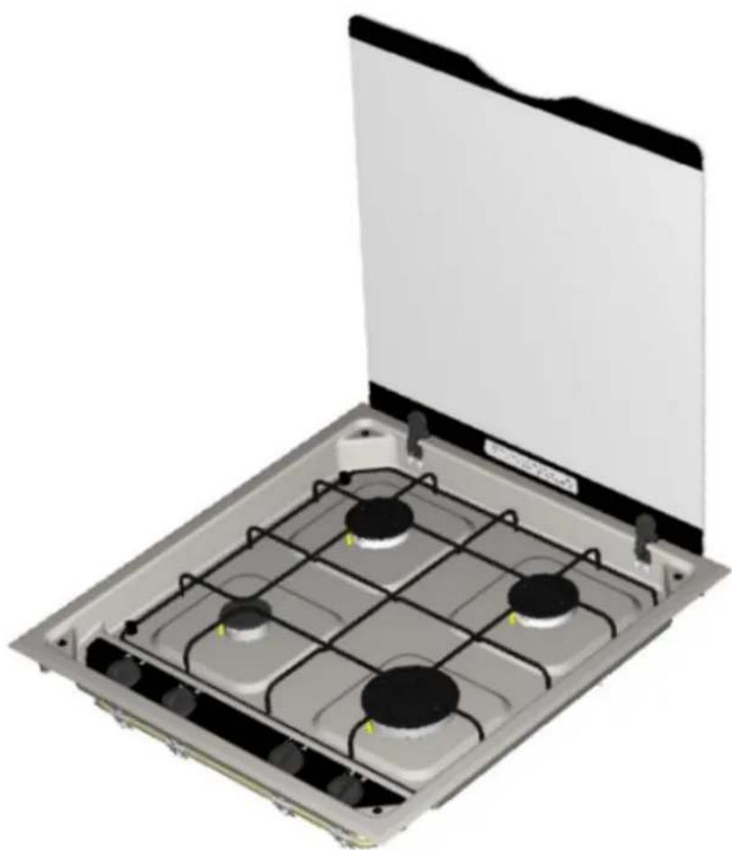
BUILD-IN COOKING HOB
FOR USE WITH LIQUIFIED PETROLEUM GAS
LINEAR Hob
SERIES 172, 173 & 174
All Gas & Dual Fuel Models
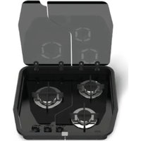
natural_image
3D rendering of a gas stove with four burners and a flat cover (no text or symbols visible)USER AND INSTALLATION INSTRUCTIONS
READ AND RETAIN FOR FUTURE REFERENCE
FOR USE IN
GAS MODELS: -
GB, BE, BG, CH, CY, CZ, DE, DK, EE, ES, FI, FR, GR, HR
HU, IE, IT, LT, LU, LV, MT, NL, NO, PT, RO, SE, SK, SI, TR
DUAL FUEL MODELS: -
GB, BE, CH, CY, CZ, DE, DK, ES, FI, FR, GR, HU
IE, IT, LT, LU, LV, MT, NL, PT, RO, SE, SK, SI
THETFORD LIMITED
Unit 6 Brookfields Way, Manvers
Rotherham S63 5DL. ENGLAND.

+ 44 (0) 844 997 1960

+ 44 (0) 844 997 1961

CAUTION

- Appliance and accessible parts become hot when in use, young children should be kept away. Avoid touching the heating elements or pan supports when in use.
- The use of a gas cooking appliance results in the production of heat, moisture and products of combustion in the room in which it is installed. Ensure that the kitchen is well ventilated especially when the appliance is in use. Keep natural ventilation holes open or install a mechanical ventilation device (mechanical extractor hood). Prolonged intensive use of the appliance may call for additional ventilation, for example opening of a window or more effective ventilation, for example increasing the level of mechanical ventilation where present.
- This appliance may be used by children aged from 8 years and above, persons with reduced physical, sensory or mental capabilities and/or lack of experience and knowledge only if they have been given supervision or instruction concerning use of the appliance in a safe way and understand the hazards involved.
- Children less than 8 years of age shall be kept away unless continuously supervised. Children shall not play with the appliance. Cleaning and user maintenance shall not be made by children without supervision.
- Unattended cooking on a hob with fat or oil can be dangerous and may result in fire. Do not leave the appliance unattended when in use.
- Never extinguish a cooking fire with water, switch off the appliance and cover the flames with a lid or fire blanket.
- Danger of Fire: Do not store items on the cooking surface.
- The use of inappropriate hob guards can cause accidents and may affect safe combustion of the appliance.
- This appliance must not be modified or adjusted unless such modification is authorized and carried out by the manufacturer or his representative. No parts other than those supplied by the manufacturer should be used on this appliance.
- Remove all spillage on surface of the glass lid before opening.
- Take care when closing the lid as the travel lock action of the hinges activates towards the end of lowering the lid.

CAUTION

- Do not allow cooking vessels to overlap the edges of the appliance – use the correct sizes of pans and position them centrally over the burners.
- Do not use harsh abrasive cleaners or sharp metal scrapers to clean the glass since they can scratch the surface, which may result in shattering of the glass.
- Do not use steam cleaners or pressure washers to clean the appliance. Refer to cleaning and maintenance instructions.
- This appliance is for cooking purposes only. It must not be used for any other purposes, for example room heating.
- Do not allow oil or fat to build up on the appliance – clean the appliance after each use.
natural_image
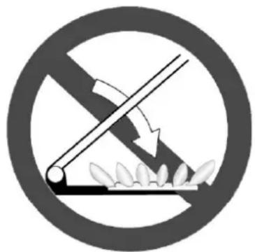
Prohibition sign showing a diagonal line crossing over plants, no text or symbols present- GLASS LID SYMBOL – Do not shut lid when burners are alight. Printed on the underside of the glass lid.
- Always make sure the control knobs are in the off position when you have finished using the hotplate burners and before closing the glass lid.
- If the supply cord is damaged, it must be replaced by the manufacturer, its service agent or similarly qualified persons in order to avoid a hazard. The appliance must be earthed.
- This appliance is not intended to be operated by means of an external timer or separate remote-control system.
| SERIES 174 | SERIES 173 | SERIES 172 | ||||||||||||
| S~HB17400 | S~HB17300 | S~HB17200 | ||||||||||||
| Metric (mm)W | H | W | D | H | W | D | H | W | D | |||||
| 110 | 520 | 550 | 110 | 520 | 550 | 110 | 520 | 550 | ||||||
| Identification: Manufacturers name on burner spreader & cup | kW | g/hr | Identification: Manufacturers name on burner spreader & cup | kW | g/hr | Identification: Manufacturers name on burner spreader & cup | kW | g/hr | ||||||
| 1x1.0kW | 0.52 | 72 | 1x1.0kW | 0.52 | 72 | |||||||||
| 2x1.5kW | 0.61 | 2x10⁸ | 2x1.5kW | 0.61 | 2x10⁸ | 1x1.5kW | 0.61 | 108 | ||||||
| 1x2.4kW | 0.77 | 173 | 1x2.4kW | 0.77 | 173 | 1x2.4kW | 0.77 | 173 | ||||||
| 1x800W 230-240V~50Hz | ||||||||||||||
| Σ kW | 6.4kW | 461 | Σ kW | 5.4kW | 389 | Σ kW | 4.9kW800W Electric | 353 | ||||||
| 12V dc | 12V dc | 12V dc | ||||||||||||
| kg | 10.0kg | kg | 9.7kg | kg | 12.0kg | |||||||||
CAT I3B/P(30)
BUTANE (G30) 30 mbar
PROPANE (G31) 30 mbar
Gas Category:
Fig.1 - Worktop Cutout

flowchart
graph TD
    A["A"] --> R1["R1"]
    B["B"] --> R1
    C["C"] --> R2["R2"]
    D["D"] --> R1
    G["G"] --> R1
    H["H"] --> R1
    R1 --> F["F"]
    R2 --> E["E"]
| A | 491mm |
| B | 475mm |
| C | 360mm |
| D | 57.5mm |
| E | 518mm |
| F | 505mm |
| G | 415mm |
| H | 52.5mm |
| R_1 | 5mm |
| R_2 | 20mm |
Fig. 2 – Minimum distance to combustible material

(A) 200mm minimum allowable distance to any adjoining combustible wall surface
(B) 510mm minimum allowable distance to any fitment above appliance.
(C) Not less than appliance width
Fig. 3 – Under hob shielding
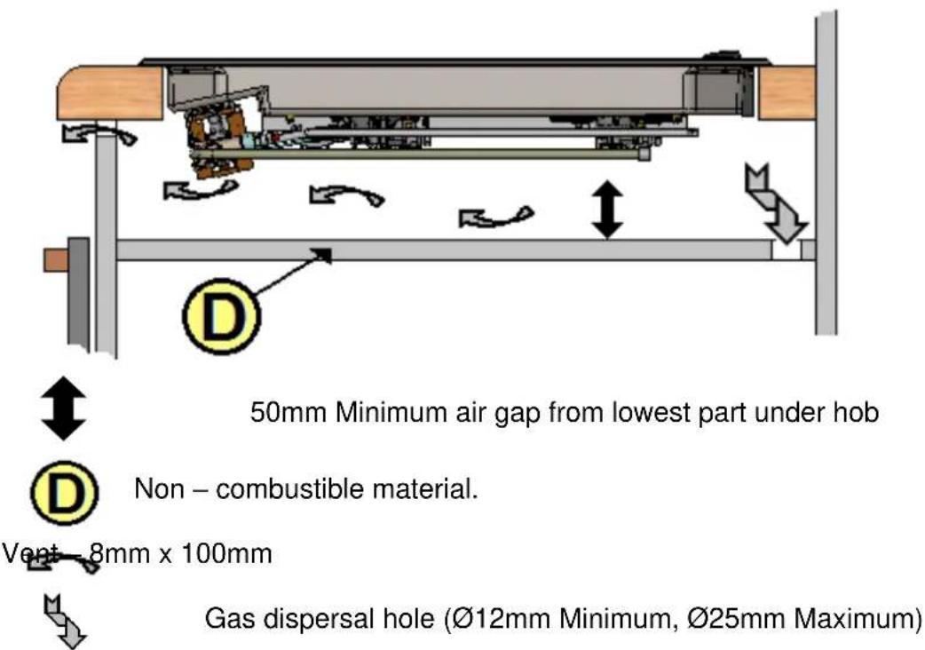
Fig. 4 – Control Positions

Fig. 5 – Wiring diagram
| 1 | GREEN & YELLOW | 2 | BLUE | 3 | BROWN | 4 | BLACK |
| 5 | RED | 6 | YELLOW | 7 | PURPLE | 8 | WHITE |
| 1 | CABLE CLAMP | 2 | ROTARY SWITCH | 3 | WARNING LAMP | 4 | HOTPLATE |
| 5 | EARTH (FASCIA) | 6 | EARTH (HOB) | 7 | HOTPLATE N^OS | ||

| Energy Consumption measurement and Calculations in Accordance with EN 60350-2 2013. | ||||
| Thetford Appliance Model Identification | Cooking Zones | Type of Hob (Watts) | Diameter of Cooking Zone | Energy Consumption EC_electric hob Wh/kg |
| Linear Dual-Fuel Hobs SHB172XX Series | 1 | 800W Solid Hotplate | 115 mm | 190.0 |
To reduce energy use on the hob whilst cooking;
- Use the correct size of pan – a pan which fits the hotplate will use less energy than one that is too large or too small.
- Use the minimum heat setting to maintain simmering or boiling – additional heat is just wasted.
- Cover pans or kettles with a lid whenever possible – this helps to retain heat.
- Do not use old, damaged or distorted pans, they will reduce efficiency.
INTRODUCTION
This appliance is designed for cooking foods, any other use is incorrect and dangerous. Failure to install the appliance correctly or improper use, will invalidate any warranty or liability claims. This appliance must be installed in accordance with the local, national and European regulations in force. Particular attention shall be given to the requirements regarding ventilation. Read the instructions before installing or using the appliance. The appliance MUST be installed by an approved competent person.
Our policy is one of continuous development and improvement. Specifications and illustrations may change subsequent to publication.
Provision of Ventilation
The use of a gas cooking appliance results in a production of heat and moisture in the room in which it is installed. Ensure that the kitchen is well ventilated: keep natural ventilation holes open or install a mechanical ventilation device, (mechanical extractor hood).
Prolonged intensive use of the appliance may call for additional ventilation, for example opening a window, or more effective ventilation, for example increasing the level of mechanical ventilation where present.
The room containing the cooker should have an air supply in accordance with local and national/European standards.
Position
This appliance must be positioned free from draughts, which may affect the combustion, and in a manner that will prevent the accumulation of unburnt gas. When in use ensure that air vents are not inadvertently blocked or shut off.

- Appliance should only be used with Liquefied Petroleum Gas (LPG)
- Use only the Gas Pressures specified
This appliance is approved for use with either Propane or Butane. We recommend using Propane for this appliance. - Butane may be used, although the appliance performance may be compromised when the ambient temperature is below 10^ .
- Butane should not be used when the ambient temperature is below 5 °C.
• This appliance MUST be earthed
OPERATION
The burners on the appliance have fixed aeration and no adjustment is required. The burners should flame as follows:-
Propane - The flames should burn quietly with a blue/green colour with no sign of yellow tips.
Butane - Normally on initial lighting, a small amount of yellow tipping will occur and then slightly increases as the burner heats up.
The burners are controlled individually and each is monitored by a thermocouple probe. In the event the burner flames are accidentally extinguished, turn off the burner control and do not attempt to re-ignite the burner for at least one minute.

Before first use, clean all surfaces with hot soapy water to remove any residual protective covering of oil the rinse and dry carefully.
Hob Burners
- Ensure gas supply is connected and turned on.
- Push in the control knob and turn anticlockwise to full rate – large flame (☐), see Fig 4.
- Continue depressing the knob whilst holding a lighted match or taper to the burner. For models fitted with 'Auto Spark' the procedure is similar except burner ignition is automatic whilst knob depressed.
- After the burner is lit continue depressing the knob for approximately 10 - 15 seconds.
- Release knob and turn to required heat setting.
- If burner has not lit within 15 seconds, release knob and wait at least 1 minute before repeating operations (2) to (5).
- To turn off, rotate the control knob until the line on the knob is aligned with dot on the control panel. Always make sure the control knob is in the off position when you have finished using the hotplate burners.
Electric Hotplate
- Ensure the electricity is switched on.
- The hotplate control is numbered from 1 (Low) to 6 (High). To turn on, rotate the knob either clockwise or anti-clockwise to the required position.
- To turn off, rotate the knob until the line or pointer on the knob lines up with the zero on the control panel.
The hotplate is a sealed construction and transfers heat through conduction. For maximum efficiency use the correct size pan with a flat heavy gauge base. The pan size should be the same or slightly larger than the hotplate (up to 1" / 2.5 cm oversize).
Before using your hotplate for the first time, we recommend that you prime and then season it.
To prime the hotplate:-
Switch on the hotplate for a short period, without a pan, to harden and burn off the coating. Use a medium to high setting for 3 – 5 minutes. A non toxic smoke may occur during this process. Allow it to cool, then season.
To season the hotplate:-
Heat the hotplate for 30 seconds on a medium setting, then switch off. Pour a minimal amount of unsalted vegetable oil onto a clean dry cloth or paper towel, and apply a thin coat of oil to the hotplate surface. Wipe off any excess oil, then heat the hotplate on a medium setting for 1 minute. Occasional seasoning will help to maintain the appearance.
OPERATION
DO'S AND DON'TS
DO Read the user instructions carefully before using the appliance for the first time.
DO Allow the burners to heat before using for the first time, in order to expel any smells before the introduction of food.
DO Clean the appliance regularly.
DO Remove spills as soon as they occur.
DO Turn pan handles away from the front so that they cannot be caught accidentally.
DO Check that controls are in the off position when finished.
DO NOT Allow children near the appliance when in use.
DO NOT Allow fats or oils to build up in the base of the hotplate.
DO NOT Use abrasive cleaners or powders that will scratch the surfaces of the hotplate.
DO NOT Under any circumstances use the appliance as a space heater.
DO NOT Exceed the pan size limits listed below.
| PERMITTED PAN SIZES | ||||
| Appliance Range | Burner Position | Burner Type | Minimum Diameter | Maximum Diameter |
| Series 172 | Front Left | Auxiliary | 100mm | 200mm |
| Rear Left | Hotplate | 110mm | 180mm | |
| Front Right | Rapid | 100mm | 200mm | |
| Rear Right | Semi-Rapid | 100mm | 180mm | |
| Series 173 | Front Centre | Rapid | 100mm | 200mm |
| Rear Left | Semi-Rapid | 100mm | 200mm | |
| Rear Right | Semi-Rapid | 100mm | 200mm | |
| Series 174 | Front Left | Auxiliary | 100mm | 180mm |
| Rear Left | Semi-Rapid | 100mm | 200mm | |
| Front Right | Rapid | 100mm | 200mm | |
| Rear Right | Semi-Rapid | 100mm | 180mm | |
Ensure there is a minimum 10mm gap between individual pans and to the edges of the hob. Ensure that the gas flame heats the bottom of the pan and not the sides.
GAS LEAKS
If a smell of gas becomes apparent, the supply should be turned off at the cylinder IMMEDIATELY. Extinguish naked lights including cigarettes and pipes. Do not operate electrical switches. Open all doors and windows to disperse any gas escape. Butane/Propane gas is heavier than air; any gas escaping will therefore collect at low level. The strong unpleasant smell of gas will enable the general area of the leak to be detected. Check that the gas is not escaping from an unlit appliance. Never check for leaks with a naked flame; leak investigation should be carried out using a leak detector spray.
INSTALLATION
Regulations and Standards
In your own interest of safety, it is law that all gas appliances are installed and serviced by an approved competent person, in accordance with the local and National/European standards in force Failure to install the appliance correctly could invalidate any warranty or liability claims and lead to prosecution. Particular attention shall be given to the requirements regarding ventilation. Read the instructions before installing or using this appliance.
Ventilation
This appliance is suitable for installation into Holiday Homes, Touring Caravans and Boats. In all cases the national standards with regard to ventilation for the particular vehicle into which the appliance is to be installed must be adhered to.
The European Standard EN1949 - "Specification for the installation of LPG systems in leisure and other road vehicles", specifies appliances be installed in accordance with the manufacturer's instructions, including the adequate provision to avoid the accumulation of unburnt gases. We recommend a floor vent, venting to the outside, with minimum size ∅12mm, maximum ∅25mm, which should be baffled to prevent direct draughts to the appliance.
Location of Appliance
This appliance may be installed in a kitchen/kitchen diner but NOT in a room containing a bath or a shower. LP gas appliances must not be fitted below ground level. e.g. in a basement.
Position
A cutout should be prepared as shown in the enclosed diagram – Fig. 1. We recommend the underside of the hob be shielded – see Fig. 3, particularly if this area is to be used for storage or the installation of another appliance. The shield should be fabricated from non-combustible material, but if the enclosure is manufactured from combustible material there should be a minimum air gap of 50mm between lowest part under hob and the shield. THIS AIR SPACE MUST BE WELL VENTILATED
The location of the cutout MUST comply with the dimensions shown and include a gas
dispersal hole venting to the outside, indicated by in the diagrams. We recommend the dispersal hole is baffled. A warning notice located near the dispersal hole with the following text is recommended.
WARNING
Under no circumstances should the gas dispersal hole be obstructed.
A horizontal distance of 200mm must exist between the edge of the burners and combustible material unless protected by a layer of non-combustible material. Unless the appliance is fitted with a glass lid a non-combustible heat shield (splash back) must be fitted onto the rear wall directly behind the appliance.
For models with a glass lid, the distance from the edge of the burner to the rear wall can be reduced to 110mm.
All combustible materials such as curtains and shelves must be kept well clear of the appliance. Any fitments such as a cupboard above the appliance must have a minimum clearance of 510mm between the fitment and the top of the pan support – see Fig. 2
The appliance should be fixed in place using the clamps provided. Make sure the appliance is fully home in the cabinet/aperture before fixing in place.
INSTALLATION
This appliance must be positioned free from draughts, which may affect the combustion, and in a manner that will prevent the accumulation of unburnt gas. When in use ensure that air vents are not inadvertently blocked or shut off. Ensure all combustible materials such as curtains and shelves are well clear of the appliance.
If other appliance/s are located below the hob we recommend conducting a temperature verification test to confirm any rise in temperature of the cabinet materials are within allowable limits and meet requirements specified in EN30-1-1, EN1949, EN1645-1, EN1646-1, EN1647, and EN721.
The performance of this appliance meets the requirements of the European Standard for Domestic Cooking Appliances (EN30) which specifies a maximum allowable temperature rise of the furniture into which the appliance is installed of 65^ C above the ambient temperature.
We recommend the installation follows the minimum dimensions shown in this manual as any deviation could result in excessive temperature rise. If minimum dimensions must be reduced, due to design constraints, a temperature rise test of all furniture fitted around the unit MUST be performed. The design is deemed permissible providing the results of this test comply with the allowable temperature rise specified above and with all standards in force. In addition comply with all requirements detailed within the furniture manufacturer's material specification. Where minimum dimensions are reduced we recommend protecting with non combustible material.
On completion of the installation a warning notice complying with EN721 Annex A should be affixed adjacent to the appliance.
Gas Connection
Prior to connection ensure the local conditions for gas type and gas pressure match the appliance specification. (Gas type and pressure for this appliance are printed on the databadge located on the base of appliance)
The ∅8mm gas inlet is located to the rear of the appliance. Prior to connection remove the plastic protection plug from the fitting. The appliance must be connected using metal pipe manufactured from either copper, seam welded steel, seamless steel or stainless steel, which complies with the requirements of EN1949, rubber tubing must not be used.

• After installation the appliance must be tested for soundness
- The gas supply pressure to which this appliance is connected must not rise or fall by more than 2.5mbar from nominal, when all appliances connected to the supply are operated simultaneously.
Electrical Connection
Spark Ignition (12V DC)
The spark ignition generator must only be connected to a suitable 12V DC supply. We recommend using sheathed spade connectors to connect the generator to the 12V battery.
INSTALLATION
Dual Fuel models (230-240V \~ 50Hz)
Models with power cord only
This appliance is supplied with a double insulated cord, type 227 IEC 53, HO5V V-F, which is suitable for use up to 4 amps. This should be connected to a double pole switched mains supply, with 3mm minimum contact separation at all poles in accordance with the wiring rules. Ensure that all electrical cables and wires are routed well clear of any heat source, including this appliance. Do not allow the cord to hang loose into the lower compartment. The switch must be accessible after installation.
Models with power cord and plug (UK only)
This appliance is supplied with a plug attached to the end of the power cord, for connection to a switched wall mounted socket. After connection ensure the power cord and any other electrical wires are routed well clear of any heat source, including this appliance. Do not allow the cord to hang loose into the lower compartment. The switched socket must be accessible after installation.

To ensure correct operation we recommend the following installation requirements:-
- Build the appliance into a self-contained cabinet which is not connected to externally vented chambers in adjacent furniture, other than correct size gas dropouts.
- Holes for cables & pipes have minimum clearance where possible
- A gas dispersal hole MUST be fitted, this must not exceed ∅25mm
- Cupboards below appliance MUST not allow gas to enter the living area.
• Air vents and gas dispersal holes MUST be kept clear - If this appliance is not installed in accordance with the instructions and tolerances detailed herein, we the manufacturer can not be held responsible for any problems that occur, or poor performance that is perceived/witnessed
MAINTENANCE
We recommend an annual service by an authorised service agent to maintain efficient appliance performance. In between annual service this appliance needs little maintenance other than cleaning. All parts should be cleaned using warm soapy water. Do not use abrasive cleaners, steel wool or cleansing powders. When cleaning the burner ring it is essential to ensure that the holes do not become blocked. The control knobs are a push fit and can be removed for cleaning. They are interchangeable without affecting the sense of operation.
The electrical components in this appliance are not user serviceable. In any event of damage, disconnect the appliance from the electrical supply and refer to an authorised Thetford Service Agent for replacement or repair.
SERVICING
All servicing must be carried out by an approved competent person. Before any service work is started the appliance should have been left to cool and be disconnected from both the gas and electrical supplies. After each service the appliance must be checked for gas soundness.
For service, please contact your authorised local Service Agent giving details of the model and serial number on the data badge plus date of purchase as shown below.
| Model Name & Series Number | |||
| G30G31 | CAT I_3 + (28/30-37)BUTANE 28-30mbarPROPANE 37mbar | CAT I_3 B/P(30)BUTANE 30mbar | THETFORD |
| Spark Ignition | |||
| ≤ Qn | Power kW (g/hr) | Voltage ~ 50Hz | |
| CE | Pin Number | Power kW | |
| Country Codes 1 | QC Pass Order No | ||
THETFORD
Unit 6 Brookfields Way, Manvers Rotherham, S63 5DL United Kingdom
Tel. +44(0) 844 997 1960
Fax. +44(0) 844 997 1961
www.thetford.eu
- BUILD-IN COOKING HOB
- LINEAR Hob
- USER AND INSTALLATION INSTRUCTIONS
- CAUTION
- To reduce energy use on the hob whilst cooking;
- INTRODUCTION
- Provision of Ventilation
- Position
- OPERATION
- Hob Burners
- Electric Hotplate
- To prime the hotplate:-
- To season the hotplate:-
- DO'S AND DON'TS
- GAS LEAKS
- INSTALLATION
- Regulations and Standards
- Ventilation
- Location of Appliance
- Gas Connection
- Electrical Connection
- Spark Ignition (12V DC)
- Dual Fuel models (230-240V \~ 50Hz)
- Models with power cord and plug (UK only)
- MAINTENANCE
- SERVICING
- THETFORD
Brand : THETFORD
Model : Linear SHB173
Category : Cooker