19R - Uncategorized ELO - Free user manual and instructions
Find the device manual for free 19R ELO in PDF.


| Product Type | 19-inch Touchscreen Monitor |
| Brand | Elo |
| Model | 19R |
| Display Size | 19 inches (viewable diagonal) |
| Resolution | 1280 x 1024 (typical) |
| Touch Technology | Resistive or surface acoustic wave (SAW) |
| Dimensions (W x H x D) | Approx. 445 x 360 x 200 mm |
| Weight | Approx. 5.5 kg |
| Power Supply | AC 100-240V, 50/60 Hz |
| Power Consumption | Less than 40W (typical) |
| Main Functions | Display, touch input, OSD controls |
| Cleaning and Maintenance | Wipe gently with a soft, dry cloth. Use mild cleaner if needed. Avoid abrasive materials. |
| Safety Instructions | Do not expose to liquids, avoid extreme temperatures, unplug during cleaning. |
| Spare Parts & Repairability | Contact Elo customer support for replacement parts. Limited user-serviceable parts. |
| General Information | Designed for commercial use, compatible with Windows and Linux via standard touch drivers. |
Frequently Asked Questions - 19R ELO
User questions about 19R ELO
0 question about this device. Answer the ones you know or ask your own.
Ask a new question about this device
Download the instructions for your Uncategorized in PDF format for free! Find your manual 19R - ELO and take your electronic device back in hand. On this page are published all the documents necessary for the use of your device. 19R by ELO.
USER MANUAL 19R ELO
Copyright © 2009 Tyco Electronics. All Rights Reserved.
No part of this publication may be reproduced, transmitted, transcribed, stored in a retrieval system, or translated into any language or computer language, in any form or by any means, including, but not limited to, electronic, magnetic, optical, chemical, manual, or otherwise without prior written permission of Elo TouchSystems.
Disclaimer
The information in this document is subject to change without notice. Elo TouchSystems makes no representations or warranties with respect to the contents hereof, and specifically disclaims any implied warranties of merchantability or fitness for a particular purpose. References in this publication to Elo TouchSystems products or services do not imply that Elo TouchSystems intends to make them available in all countries in which Elo TouchSystems operates. Elo TouchSystems reserves the right to revise this publication and to make changes from time to time in the content hereof without obligation of Elo TouchSystems to notify any person of such revisions or changes.
Trademark Acknowledgments
IntelliTouch, SecureTouch, AccuTouch, and MonitorMouse are trademarks of Elo TouchSystems. Other product names mentioned herein may be trademarks or registered trademarks of their respective companies. Elo TouchSystems claims no interest in trademarks other than its own.
Table of Contents
Setup 5
Unpacking Your Touchcomputer 5
Product Overview 6
Front View 6
Rear View 6
Side View 7
Base Bottom View 7
Display Orientation 8
Initial Connections 9
Standard Unit: 9
Advanced Unit: 9
Initial Power-On 10
Language Selection 10
Test Devices 11
Testing the Touchscreen 11
Time-zone selection 11
Operation 13
Side Panel Controls 14
OSD Control 14
OSD Menu 14
Headphone Jack 16
Power Control 17
Power Button 17
Using the I/O panel 18
Standard Unit: Intel® Desktop Board D945GCLF2 18
Advanced Unit: Intel® Desktop Board MS-9820 19
Short Base Mounting 21
Securing the Touchcomputer Base 21
Mounting To A Wall 21
Display Angle 22
Wall Mounted 22
Desktop 22
Maintenance 23
Care and Handling 23
Warning 24
Waste Electrical and Electronic
Equipment (WEEE) Directive 24
Technical Specifications 25
Touchcomputer Specifications 25
Dimensional Diagrams 25
Front 25
VESA 26
Rear 26
Base Mounting 27
General Information 28
Standard Unit: Intel® Desktop Board D945GCLF2 28
Advanced Unit: Intel® Desktop Board MS-9820 29
Display Specifications 33
Power Supply Specifications 33
Touchscreen Specifications 34
Environmental Specifications 34
Hard Disk Recovery 35
Materials required 35
General overview: 36
Begin: 36
Technical Support 45
Technical Assistance 45
Using the Touchcomputer 45
Using the Web 45
Using the Phone 45
Regulatory Information 46
Warranty 49
1
Setup
This chapter discusses how to set up and test your Touchcomputer and any included peripheral options.
Unpacking Your Touchcomputer
Check that the following items are present and in good condition:
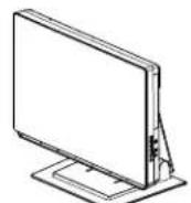
Touchcomputer
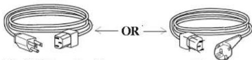
Power cable US/Canadian European power cable
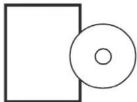
natural_image
Simple geometric diagram with a rectangle and a circle, no text or symbols presentQuick Install Guide & CD/DVD
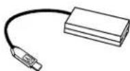
Power Adapter
Front View
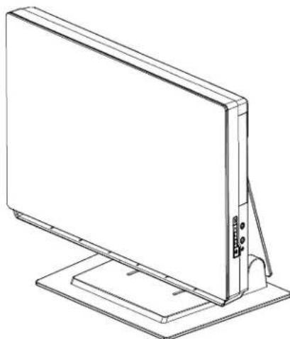
natural_image
Line drawing of a flat-screen monitor mounted on a stand (no text or symbols)Rear View
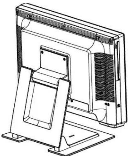
natural_image
Technical line drawing of a computer monitor with mounting base and side panel (no text or symbols)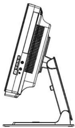
natural_image
Line drawing of a computer monitor with stand (no text or symbols)Base Bottom View
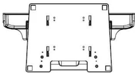
natural_image
Technical line drawing of a mechanical component with mounting brackets and internal features (no text or symbols)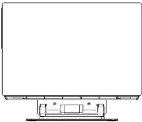
natural_image
Technical line drawing of a flat-panel electronic device with mounting base (no text or symbols)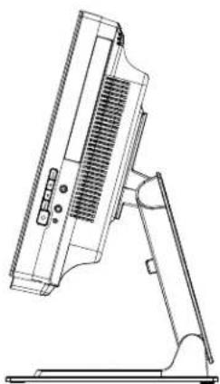
natural_image
Technical line drawing of a computer monitor with ventilation slots and stand (no text or symbols)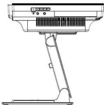
natural_image
Line drawing of a handheld electronic device with no visible text or symbolsInitial Connections
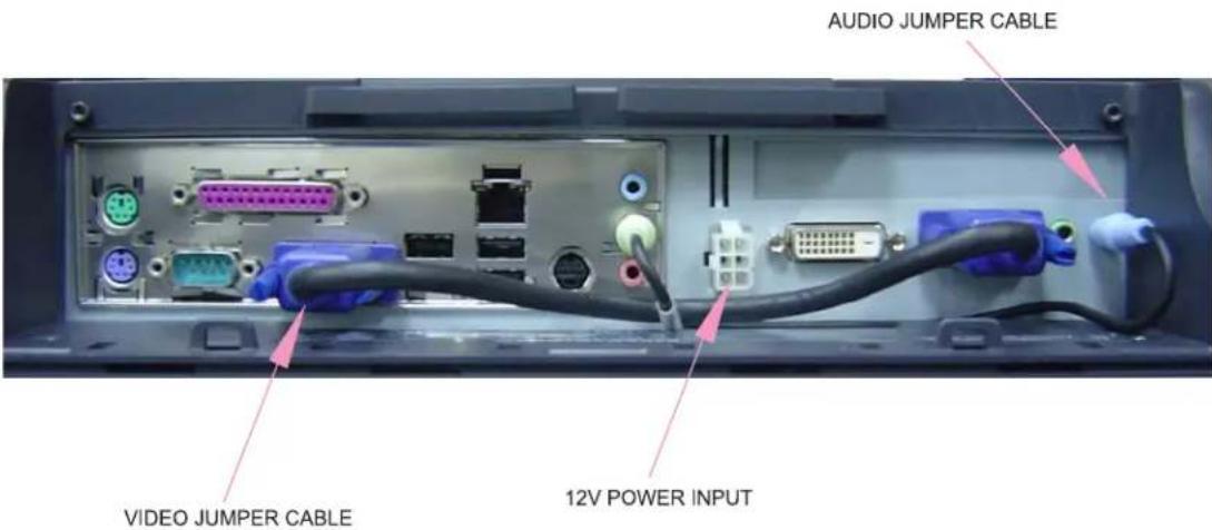
Prior to turning on your Touchcomputer you must take the power adapter and appropriate power cable from the accessories box. Plug the small round plug with four pins into the 12Vdc power input on the Touchcomputer. Plug the power cable into the power adapter and the other end into a suitable power outlet (mains). Make sure the audio jumper cable and video jumper cable are in place as shown below.
Standard Unit:
Intel: Integrated Dual-core Intel® Atom™ 1.6 GHz processor & 533 MHz system bus
Intel Core 2 Duo E5300 2.6 GHz, 800 MHz FSB, 2 MB L2 Cache
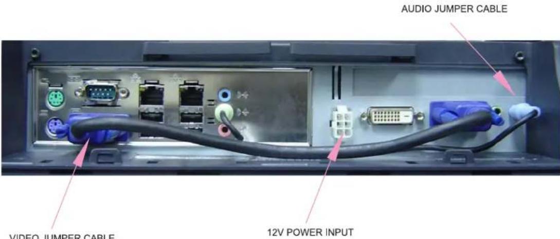
The initial setup of the operating system takes approximately 5-10 minutes. Additional time may be needed depending on touchcomputer hardware configuration and connected devices. To setup the Windows Operating System (OS) for the touchcomputer, turn on the touchcomputer and follow the instructions on the screen.
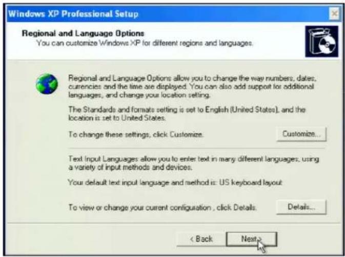
Language Selection
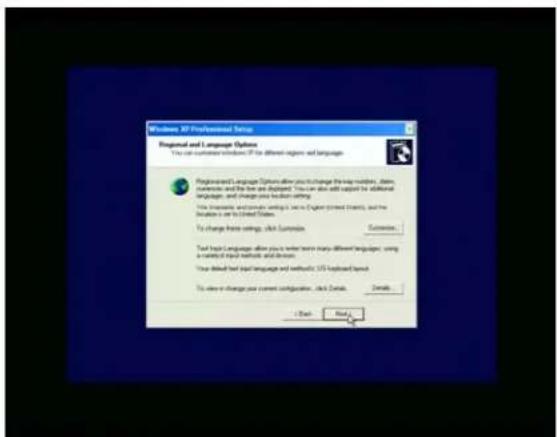
When the following window appears, you have the option of changing the language used in menus and dialogs.
Click Customize. The Regional and Language window shown below will appear.
Select the Language tab. The window shown below will appear.
Select the desired language in the drop-down list labeled Language used in menus and dialogs.
Time-zone selection
When the following window appears, you may change the time-zone, date, and/or time of the touchcomputer.
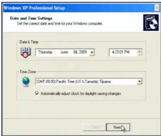
After making any changes, click Next to finish. Windows Setup will complete the initialization of the touchcomputer.
Test Devices
Testing the Touchscreen
The touchscreen is pre-calibrated for accurate touch response.
Calibration\*
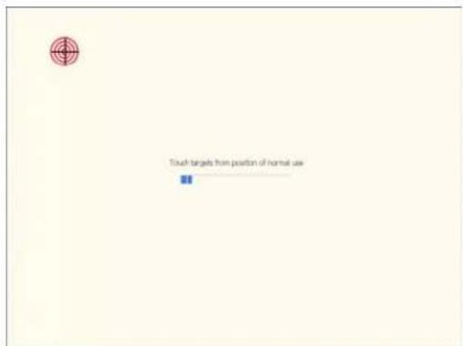
If for any reason the touchscreen needs to be re-calibrated, go to the control panel and double-click the Elo Touchscreen icon. The window shown below will open.
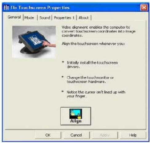
Click on the Align button. This launches the align/calibration program. A window similar to the one shown below will open. Follow the instructions to align/calibrate the touchscreen.
*The alignment/calibration procedure may vary between touch technologies.
2
Operation
This chapter shows the user how to: control the On-Screen Display (OSD) and Power buttons, use the I/O panel, securely mount the Touchcomputer and adjust the display head.
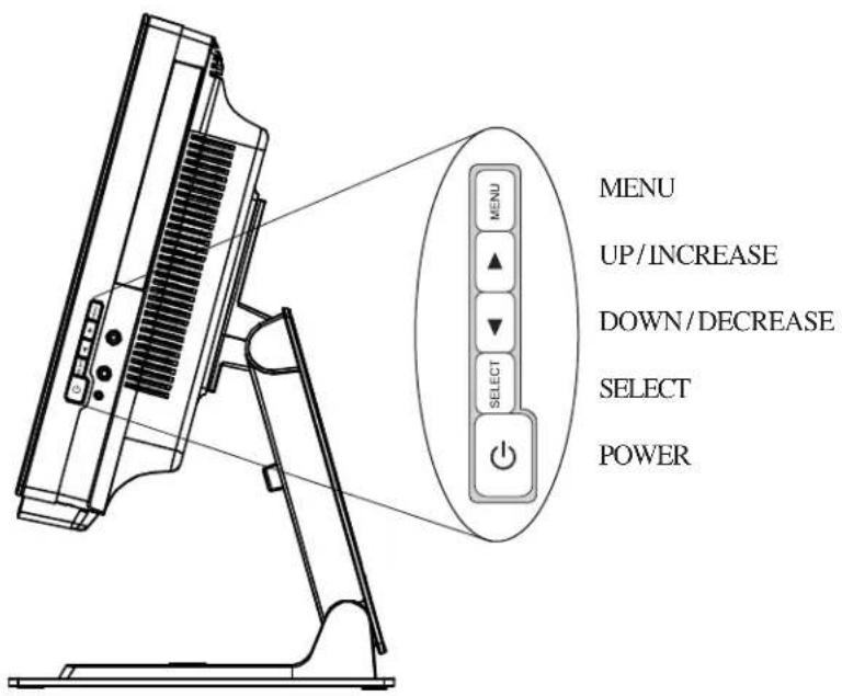
All adjustments made to the display via OSD and Power controls are automatically saved. User settings will remain unchanged after powering off/on or in the case of a power failure.
lortnoC noitcnuF
1 Menu/Exit Opens On Screen Display (OSD) / Exits the OSD menu.
2 Up

- Enter contrast adjustment.
- Increase value of the selected item.
- Move OSD selection clockwise.
3 Down

- Enter brightness adjustment.
- Decrease value of the adjustment item.
- Move OSD selection counter-clockwise.
4 Select
- VGA/DVI video source select.
- Selects the adjustment item from the OSD menu.
5 Power

- Press to turn on the computer.
- To turn off the computer use the operating system to shut down the computer. If unable to use the operating system for shutdown, press and hold the POWER button for 4-5 seconds.
OSD Control
OSD Menu
To display the OSD Menu, press the Menu button.
- Press the UP button or DOWN button to toggle and the SELECT button to select among the different OSD sub-menus and functions.
- When the function you want to change is shown, press the SELECT button.
To adjust the value of the function:
- Pressing the UP button increases the value of the selected OSD control option.
- Pressing the DOWN button decreases the value of the selected OSD control option.
The OSD shall control the following audio and screen characteristics:
| PARAMETER ADJUSTMENT | |
| Auto AdjustAutomatically adjusts the system clock to the input video signal. | |
| LuminanceBrightness Adjusts the Brightness signal from 0 (minimum brightness) to 100(maximum brightness). Default: 100 (maximum brightness)Contrast Adjusts the contrast of the video signal from 0 (minimum) to 100(maximum). Default: 50. | |
| Image settingH-position Moves the image horizontally in single-pixel increments on a scale from 0 to 100 using at least 100 discrete steps. Default: 50 (centered in the panel).V-position Moves the image vertically in single-pixel increments on a scale from 0 to 100 using at least 50 discrete steps. Default: 50 (centered in the panel).Clock Adjusts the ratio of dividing frequency of the dot clock on a scale from 0 to 100 using at least 100 discrete steps. Default:50Phase Adjust the phase of the panel dot clock with respect to panel data frequency from 0 to 100 using at least 25 discrete steps. Default:62 | |
| Color Adjusts color temperature. Color temperature options shall be 9300K,7500K, 6500K, 5500K, and User Color.Default: User Preset | |
| AudioMute Turn on or off the mute function. Default value: Not muted.Volume Adjusts the level of the audio signals to the Audio Output and PhoneOutput signals from 0 (minimum volume) to 100 (maximum volume) in 100 discrete steps. Default value: 50. | |
| OSDOSD V-Position Moves the OSD display vertically from the bottom edge to the top edge of the panel from 0 to 100. Default: 50 (centered in the panel).OSD H-Position Moves the OSD display horizontally from the left edge to the right edge of the panel from 0 to 100. Default: 50 (centered in the panel).OSD Timeout Adjusts the OSD timeout time. OSD setting changes made prior to the OSD timeout are kept and used. At a minimum, the user shall be able to select options between 5 to 60 seconds. Default: 15 seconds.OSD Language Selects which language the OSD information is displayed in. Options shall be: English, French, Italian, German, Spanish, Simplified Chinese, Traditional Chinese and Japanese. Default: English. | |
| RecallColor RecallRecall Defaults | Selecting “Color Recall” shall restore all factory default settings for the color temperature.Selecting “Recall Defaults” shall restore all factory default settings for the OSD. |
| MiscellaneousAspect Ratio Select between “Fill Screen” (input image is scaled to fill the LCD vertically and horizontally with no over- or under-scan) and “Fill to Aspect Ratio” (for input images with aspect ratio lower than the LCD panel’s aspect ratio of 16:10, input image is scaled to preserve input aspect ratio with no over-scan, & the unused portions of the panel will be black).Default: Fill Screen.Sharpness Adjusts sharpness of video signals on a scale from 1 to 5 using steps.DDCCI Function Enable or Disable DDCCI Function.Default: Enable |
| Exit Exits the OSD display. |
Shortcut keys
There are three shortcut buttons allowing the user to make quick adjustments. These shortcuts are available only when the OSD menu is NOT displayed.
- To adjust luminance, press the UP button.
- To adjust audio, press the DOWN button.
- To select video source, press the SELECT button.
OSD Lockout
The On Screen Display (OSD) feature can be locked out (disabled) if desired. To enable this feature, when the OSD is not present, simultaneously press the MENU and UP buttons until OSD LOCK appears on the screen (approximately 2 seconds). To re-enable the OSD function again, simultaneously press the MENU and UP buttons until OSD UNLOCK appears on the screen (approximately 2 seconds).
Headphone Jack
natural_image
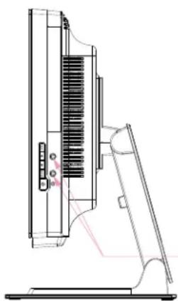
Technical line drawing of a mechanical device with internal components and a handle (no text or symbols)3.5mm stereo haedphone jack
Power Button
The power button function can be set by the operating system under:
Control Panel->Display Properties->Screen Saver->Power->Advanced->Power Buttons.
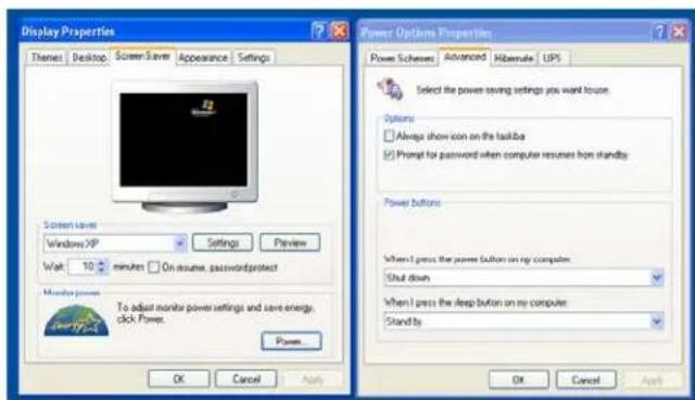
To override all Operating System settings and shut down the Touchcomputer, press and hold the power button for 4-5 seconds.
Note: On select models the delay to override the operating system is extended to 15 seconds.
The Touchcomputer provides the following I/O interfaces for connecting a wide variety of compliant devices.
Standard Unit: Intel® Desktop Board D945GCLF2
VGA
There is one VGA (HD-15) port (normally connected with supplied jumper cable to display VGA input).
USB
There are four USB 2.0 type A ports.
Ethernet
There is one RJ45 Ethernet port providing LAN capabilities.
Serial
There is one RS232 serial port.
Microphone Input
There is one 3.5 mm microphone input jack for connecting an external microphone.
Audio Output
There is one 3.5 mm stereo audio output jack for connecting headphones, normally connected with the supplied jumper cable to the audio input of the display.
PS/2 Keyboard
A PS/2 keyboard is functional when connected directly to the PS/2 keyboard port.
PS/2 Mouse
A PS/2 mouse may be connected to the PS/2 mouse port.
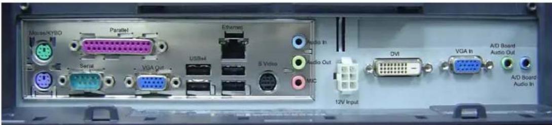
Intel® Desktop Board D945GCLF2
Advanced Unit: Intel® Desktop Board D MS9820
VGA
There is one VGA (HD-15) port (normally connected with supplied jumper cable to display VGA input).
USB
There are four USB 2.0 type A ports.
Ethernet
There are 2 RJ45 Ethernet ports providing LAN capabilities.
Serial
There is one RS232 serial port.
Microphone Input
There is one 3.5 mm microphone input jack for connecting an external microphone.
Audio Output
There is one 3.5 mm stereo audio output jack for connecting headphones, normally connected with the supplied jumper cable to the audio input of the display.
PS/2 Keyboard
A PS/2 keyboard is functional when connected directly to the PS/2 keyboard port.
PS/2 Mouse
A PS/2 mouse may be connected to the PS/2 mouse port.
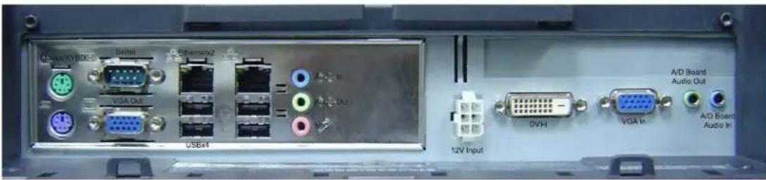
Intel® Desktop Board D MS9820
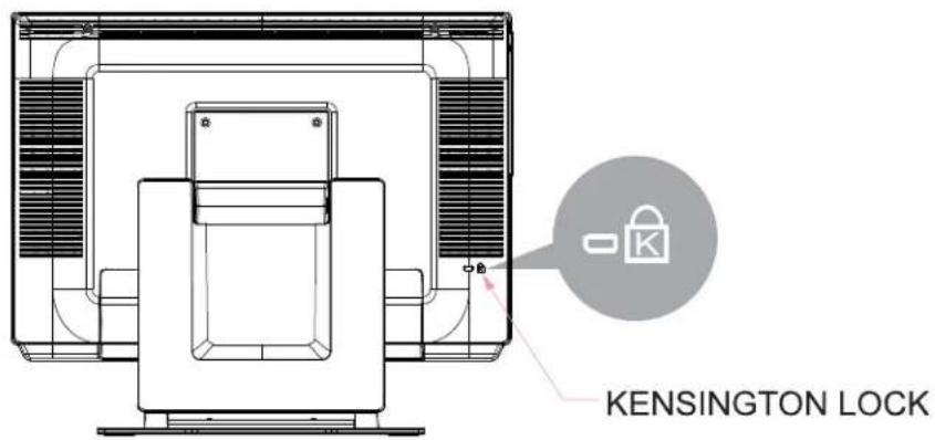
Kensington Lock
The Kensington lock is a security device that prevents theft. To find out more about this security device, look for Computer Locks on the Kensington website at: http://www.kensington.com.
Short Base Mounting
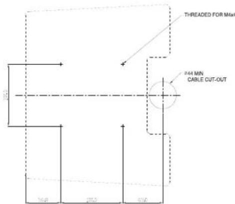
Dimensions are in millimeters.
Mounting To A Wall
-
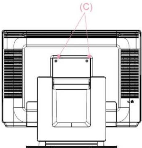
Remove the four screws (C), two are under the base assembly, in order to separate the stand from the computer.
-
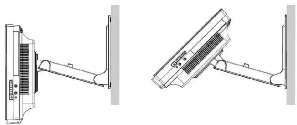
Rotate the monitor 180^ (so the monitor will not be upside down when mounted in the position shown).
-
Reinstall the four screws (C).
-
Route the cables through the cutout (if applicable) and mount the monitor to the wall using the templates provided.
natural_image
Technical line drawing of a mechanical or electrical component with no visible text, numbers, or symbols.Wall Mounted
natural_image
Technical line drawings of two mechanical components with no visible text or symbolsDesktop
natural_image
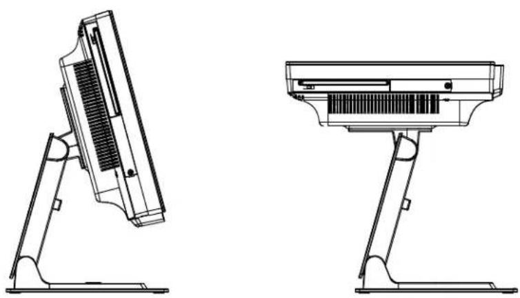
Technical line drawings of a computer monitor stand, showing front and side views (no text or symbols)For viewing clarity, you can tilt the desktop LCD from 30 to 75 degrees from vertical.
CAUTION In order to protect the LCD if no touchscreen is installed, be sure to hold the base when adjusting the LCD, and take care not to touch the LCD screen.
3
Maintenance
Care and Handling
The following tips will help keep your Elo Touchcomputer functioning at the optimal level.
- To avoid risk of electric shock, do not disassemble the power adapter or Touchcomputer cabinet. The unit is not user serviceable. Remember to unplug the computer from the power outlet before cleaning.
- Do not use alcohol (methyl, ethyl or isopropyl) or any strong solvent. Do not use thinner or benzene, abrasive cleaners or compressed air.
• To clean the computer cabinet, use a cloth lightly dampened with a mild detergent. - Avoid getting liquids inside your Touchcomputer. If liquid does get inside, have a qualified service technician check it before you power it on again.
- Do not wipe the screen with a cloth or sponge that could scratch the surface.
- To clean the touchscreen, use window or glass cleaner, apply the cleaner on a soft cloth, then wipe the touchscreen clean. Never apply the cleaner directly to the
touchscreen.

natural_image
Cartoon illustration of eight different characters, including a robot, a computer, and a sun (no text or symbols)Warning
This product consists of devices that may contain mercury, which must be recycled or disposed of in accordance with local, state, or federal laws (within this system, the backlight lamps in the monitor display contain mercury).

Waste Electrical and Electronic Equipment (WEEE) Directive
In the European Union, this label indicates that this product should not be disposed of with household waste. It should be deposited at an appropriate facility to enable recovery and recycling.
4
Technical Specifications
Touchcomputer Specifications
Note: Not all operating systems or options are supported in all regions. Please contact your local Elo TouchSystems representative for details.
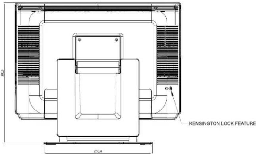
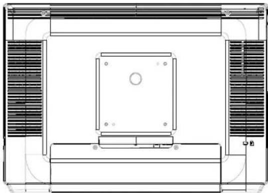
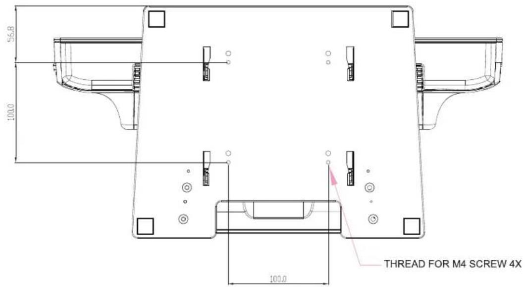
Dimensional Diagrams
Front
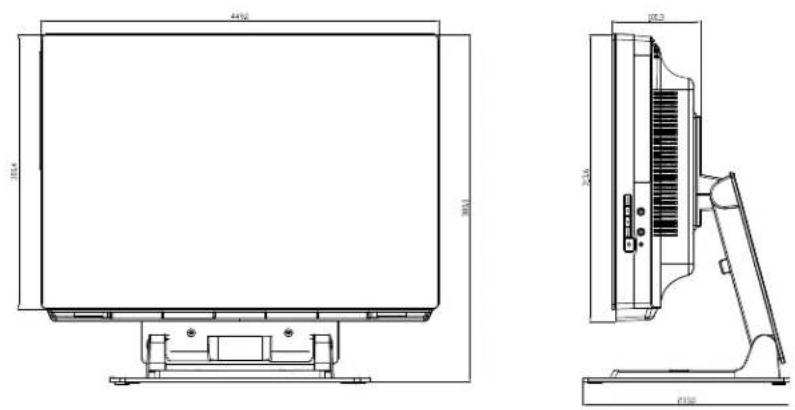
NOTE: Technical specifications are subject to change without notice.
Rear
VESA
natural_image
Technical line drawing of a room layout with ventilation grilles and a central rectangular component (no text or symbols)Base Mounting
General Information
Shipping box dimensions 555 mm x 455 mm x 260 mm (21.8 x 17.9 x 10.2 inches)
Backlight lamp life Min 40,000 hours to half brightness
Agency approvals UL/cUL (*recognized component), FCC, C-Tick, CE (EN60950)
Speakers (internal) Two-watt/channel speakers in display head
User controls Right side: Power and user display controls: turn on the Touchcomputer and adjust the display brightness, contrast and other features
Mounting options 100 mm VESA mount, removable base
Other features Adjustable Base
Energy save mode (less than 2 watts) Touchscreen sealed to bezel and LCD Security lock receptacle
Standard Unit: Intel® Desktop Board D945GCLF2
Processor Integrated dual-core Intel® Atom™ 1.6GHz processor with a 533 MHz system bus
RAM 1 GB DDR2 533/667 SDRAM, One 240-pin DIMM socket expandable to 2 GB max (not user serviceable)
Chipset Intel 82945GC Express Chipset Graphics and Memory Controller Hub (GMCH) Intel 82801GB I/O Controller Hub (ICH7)
Video Integrated graphics via the Intel® Graphics Media Accelerator 950 (Intel® GMA 950) & S-video output support
BIOS Intel BIOS
Operating system (optional) Windows XP Embedded, Microsoft Windows Embedded for Point of Service (WEPOS)
Rear I/O VGA: 1
S-Video: 1 (may not be present on some part numbers)
Ethernet: 1 (10/100/1000Base-T)
USB: 4 USB 2.0
Audio: Mic in, Line in, Line out
(Realtek ALC662 supports 5.1 CH HD Audio)
Parallel: 1
Serial: 1 (RS-232)
PS/2: 2 (1 x K/B and 1 x Mouse)
Additional Internal I/O Ports USB: 2 (USB 2.0) S/PDIF: 1, IDE: 1 (44 Pin), SATA: 2
(connectors on motherboard - not user serviceable)
Real Time clock Replaceable Lithium battery backed up real time clock
Hard Drive 1 x 2.5" SATA hard drive, 80GB
Power supply Type: External
Input (line) voltage: 100-240 VAC, 50-60 Hz, 2.0 Amp.
Output voltage/current: 12 V at 9.165 Amp. min.
110 watts minimum
Power dissipation 110 W Typical
Weight Actual: 20.1 lbs (9.14 kg)
Actual without stand: 13.9bs (6.34 kg)
Shipping: 29.6lbs (13.44 kg)
Advanced Unit: Intel® Desktop Board MS9820
Processor Intel Core 2 Duo 53002.6 GHz, 800 MHz FSB, 2MB
L2 Cache
RAM 2GB DDR2 667 SDRAM, Two 240-pin, DDR2 1.8 V
SDRAM Dual Inline Memory Module (DIMM)
sockets 800/667 MHz single or dual channel DDR2
SDRAM interface
Support for up to 4 GB of system memory (not user serviceable)
Chipset Intel 82Q35 Express Chipset Graphics and Memory
Controller Hub (GMCH)
Intel® 82801IO I/O Controller Hub (ICH9DO)
Graphics/Video Intel® Graphics Media Accelerator 3100 onboard
graphics subsystem
BIOS AMI BIOS
Operating system (optional) Microsoft Windows XP Embedded, Microsoft Windows Embedded for Point of Service (WEPOS)
Rear I/O VGA:1
Ethernet: 2 (10/100/1000Base-T)
USB: 4 USB 2.0
Audio: Mic in 1, Line in 1, Line out 1 (Realtek ALC888 supports 5.1 CH HD Audio)
Serial (RS232)
PS/2: 2 (1 x K/B and 1 x Mouse)
Additional Internal I/O Ports USB: 4 USB 2.0 via two headers (connectors on Moth-
erboard - some restrictions may apply - not user serviceable)
PCI Express X16: 1 (connectors on Motherboard - some restrictions may apply - not user serviceable)
Mini-PCIe: 1 (not user serviceable)
Serial: 1 serial port header (not user serviceable)
Real Time clock Replaceable Lithium battery backed up real time clock
Hard Drive 1 x 2.5" SATA hard drive, 160 GB
Power supply Type: External
Input (line) voltage: 100-240 VAC, 50-60 Hz, 2.0 Amp.
Output voltage/current: 12 V at 9.165 Amp. min.
110 watts min.
Power dissipation 110 W Typical
Weight Actual: 21 lbs (9.5 kg)
Actual without stand: 14.7lbs (6.7 kg)
Shipping: 30.3lbs (13.8 kg)
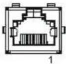
RJ45 connector Pin Definition
| Pin # T568A Wiring T568B Wiring | |||
| 1 Pair | 3 - white/green Pair 2 - white/orange | ||
| 2 Pair | 3 - green Pair 2 - orange | ||
| 3 Pair | 2 - white/orange | Pair | 3 - white/green |
| 4 | Pair 1 - blue | Pair 1 - blue | |
| 5 Pair | 1 - white/blue | Pair | 1 - white/blue |
| 6 Pair | 2 - orange | Pair | 3 - green |
| 7 | Pair 4 - white/brown | Pair 4 - white/brown | |
| 8 Pair | 4 - brown | Pair | 4 - brown |
DB9 connector Pin Definition
| Pin # | Signal Name |
| 1 | |
| 2 | Receive Data (RD) |
| 3 | Transmit Data (TD) |
| 4 | |
| 5 | Signal Ground |
| 6 | |
| 7 | Request to send (RTS) |
| 8 | Clear to Send (CTS) |
| 9 |
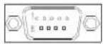
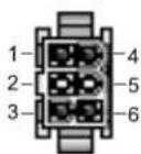
Power Input Pin Definition
| Pin # Signal | Name |
| 1+12V | |
| 2N.C | |
| 3 Ground | |
| 4+12V | |
| 5 N.C | |
| 6 Grand |
Model 19R series
LCD Display 19.0" TFT Active Matrix Panel
Display Size 408.24 (H) x 255.15 (V)
Pixel Pitch 0.2835 (H) x 0.2835 (W)
Display Mode 1680 x 1050 at 60Hz
1440 x 900 at 60 Hz
1366 x 768 at 60 Hz
1360 x 768 at 60 Hz
1280 x 1024 at 60 or 75 Hz
1280 x 960 at 60 Hz
1280 x 768 at 65 Hz
1152 x 864 at 75 Hz
1024 x 768 at 60, 65, 72 or 75 Hz
832 x 624 at 75 Hz
800 x 600 at 56, 60 or 72 Hz
720 x 400 at 70 Hz 720 x 350 at 70 Hz
640 x 480 at 60, 66 or 72 Hz
Native XGA 1440x 900
Contrast Ratio 800:1 (typical)
Brightness
LCD 3000 cd/m
^2 (Typical)
Acoustic Pulse Recognition 270 cd/m ^2 (Typical)
Response Time Tr = 3.6 ms, Tf = 1.4 ms typical
Display Color 16.7 million colors (RGB 6-bit + FRC data)
Viewing Angle (L/R) = -85° / +85° (typical),
(U/D) -80^ / + 80^ (typical)
Plug & Play DDC2B
Touch Panel Acoustic Pulse Recognition
The Touchcomputer shall be powered by 12 VDC from the power adapter supplied with the unit.
Standard unit: 12Vdc at 9.165 amps (Part number: E98499)
Touchscreen Specifications
Available with Acoustic Pulse Recognition (APR) technology. For detailed specifications, please visit our website at www.elotouch.com. Note: Touch options may vary depending on region.
Environmental Specifications
Temperature
Operating Temperature (Independent of altitude) 0^ C to 40^ C
Non-Operating Temperature (Independent of altitude) -20°C to 60°C
Humidity
Operating (noncondensing) 20% to 80%
Non-Operating (38.7 ^ C maximum wet bulb temperature) 5% to 95%
Altitude
Operating 0 to +12,000 feet [3,658 m]
Non-Operating 0 to +40,000 feet [12,192 m]
Equivalent to 14.7 to 10.1 psia
Equivalent to 14.7 to 4.4 psia
5
Hard Disk Recovery
Note: Back up all data. This procedure will erase all data from the hard drive. You will lose all previous work not backed up.
Materials required
•USB CD/DVD drive device
- USB cable
•Keyboard (PS2 or USB)
- Mouse
- Elo Recovery CD-ROM or DVD disc supplied with this computer
Note: The Elo Recovery CD supplied with the Elo Touchcomputer is specific to the 19R series Touchcomputer. Do not attempt recovery with a Recovery CD from another computer version. If do not have the correct recovery CD or you have questions about this process, contact Elo.
General overview:
- User boots off the CD.
- Select the option to recover operating system.
- The system restarts into mini setup.
- Follow the on screen instructions to enter required information by Windows setup.
- The system restarts and either touchscreen calibration/alignment is performed, or touchscreen drivers are installed and the calibration file is downloaded, and the computer restarts (Final restart).
- After the computer starts again it boots to a Windows desktop and is ready for the user to personalize.
Begin:
1. Boot off the Elo supplied recovery CD.
Turn the computer off.
Install the external USB CD/DVD drive as directed by the manufacturer.
Insert the Elo Recovery CD into the USB CD/DVD drive.
Turn on the Elo Touchcomputer.
When the screen below appears press the F10 key on the keyboard.
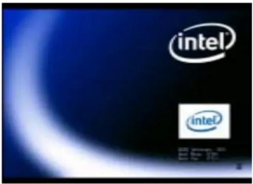
Wait until the screen below appears.
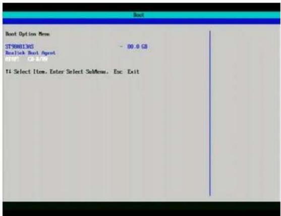
Using the Arrow UP or DOWN key(s) on the keyboard to select the CD/DVD drive you are using. When selected press ENTER.
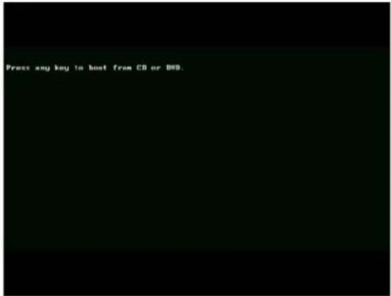
When prompted, press any key to boot from the CD.
The following two screens should appear.
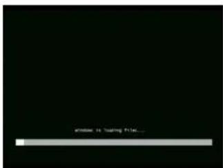
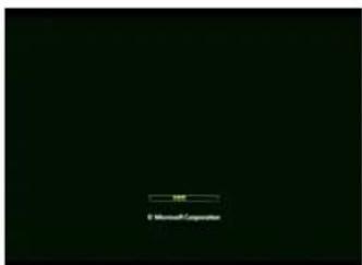
- Select the option to recover operating system.
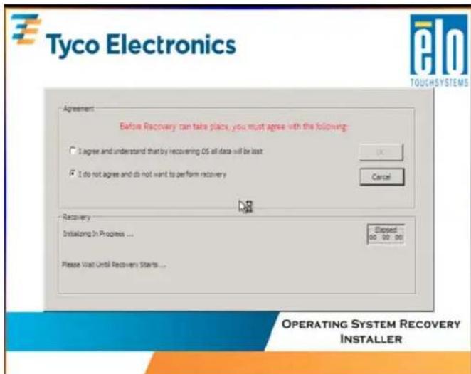
Note: By clicking, agree and understand..." and clicking OK on this screen, you are acknowledging this recovery process will erase all previous data from the hard drive. You will lose all previous work not backed up.
Click "I agree..." and then OK.
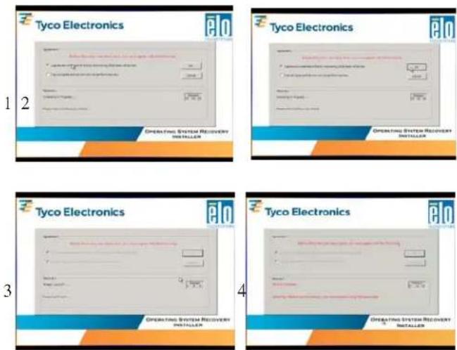
Unplug the USB device which contains the recovery software when directed to do so on the screen (see screen shot #4.)
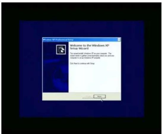
- The system restarts into mini setup.
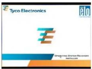
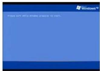
- Follow the on screen instructions.
Click NEXT.
Read and accept the End User License Agreement.
XP License Agreement
WEPOS License Agreement
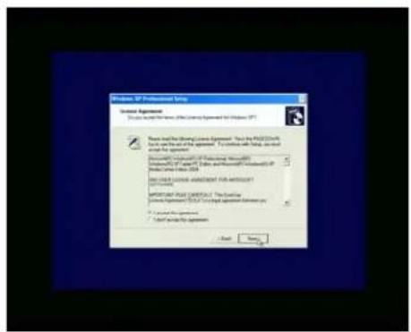
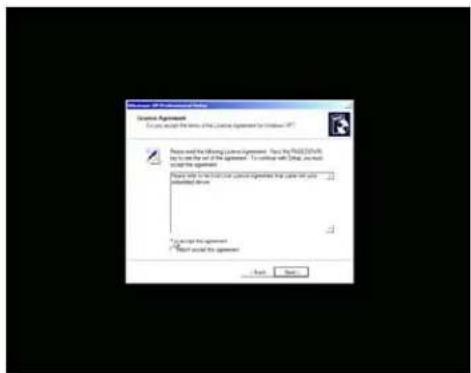
Follow the instructions on the screen.
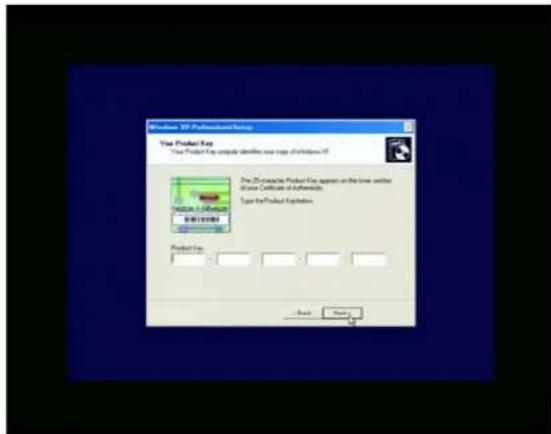
For Windows XP you will be required to enter the 25 digit product ID from the license on the back of the computer. You may have to remove the cable cover to see the license.
Note: This step not required for WEPOS.
Enter information as required.
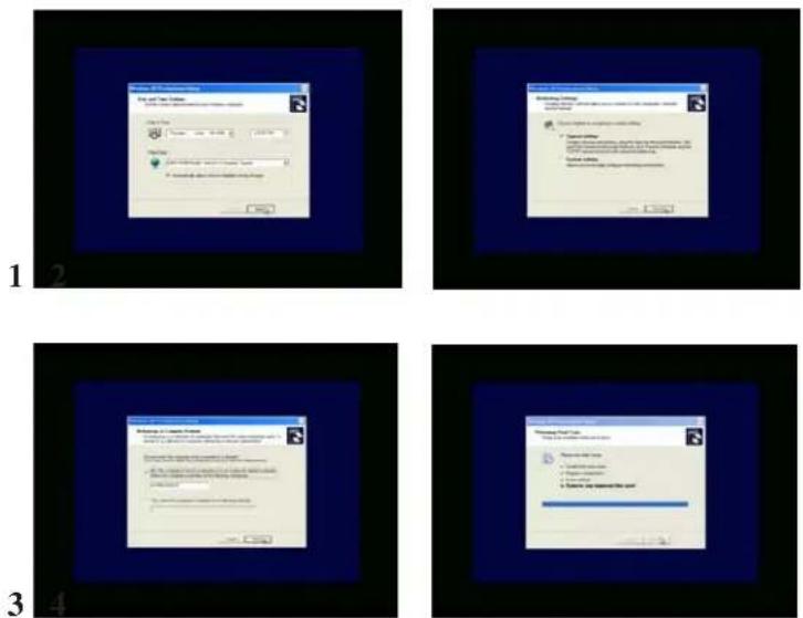
- The system will restart.
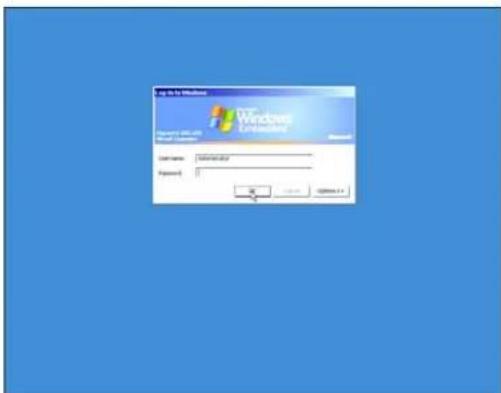
WEPOS will require you to log on to the administrator account. If you chose a password during Mini Setup you will be required to enter it now.
- Touchscreen calibration or alignment begins.
For APR (Acoustic Pulse Recognition) touch technology.
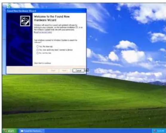
If the "Found New Hardware Window" pops up on the screen (see below)
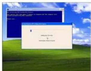
DO NOT interact with this window. It will close itself as the APR drivers load automatically.
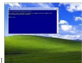
The APR drivers will load automatically. You will see the following two screens appear as the drivers load. Please wait until the computer reboots.
- Congratulations - your operating system has been restored to the original factory configuration and is ready for use.
Technical Support
Technical Assistance
There are three methods to obtain contact information for technical assistance on the Touchcomputer:
- The Touchcomputer.
• The web. - The phone.
Using the Touchcomputer
You can access the support information by going to the System Properties and clicking on the Support Information button. You can get to System Properties by either of the following methods:
- Right click "My Computer" and choose "Properties"
or - Click on the "Start Button" and select "Control Panel" and Double click on the "System" icon.
Using the Web
www.elotouch.com/go/contactsupport.
Using the Phone
Call toll-free 1-800-557-1458
Regulatory Information
I. Electrical Safety Information:
A) Compliance is required with respect to the voltage, frequency, and current requirements indicated on the manufacturer's label. Connection to a different power source than those specified herein will likely result in improper operation, damage to the equipment or pose a fire hazard if the limitations are not followed.
B) There are no operator serviceable parts inside this equipment. There are hazardous voltages generated by this equipment which constitute a safety hazard. Service should be provided only by a qualified service technician.
C) This equipment is provided with a detachable power cord which has an integral safety ground wire intended for connection to a grounded safety outlet.
1) Do not substitute the cord with other than the provided approved type. Under no circumstances use an adapter plug to connect to a 2-wire outlet as this will defeat the continuity of the grounding wire.
2) The equipment requires the use of the ground wire as a part of the safety certification, modification or misuse can provide a shock hazard that can result in serious injury or death.
3) Contact a qualified electrician or the manufacturer if there are questions about the installation prior to connecting the equipment to mains power.
II. Emissions and Immunity Information
A) Notice to Users in the United States: This equipment has been tested and found to comply with the limits for a Class A digital device, pursuant to Part 15 of FCC Rules. These limits are designed to provide reasonable protection against harmful interference in a residential installation. This equipment generates, uses, and can radiate radio frequency energy, and if not installed and used in accordance with the instructions, may cause harmful interference to radio communications.
B) Notice to Users in Canada: This equipment complies with the Class A limits for radio noise emissions from digital apparatus as established by the Radio Interference Regulations of Industry Canada.
C) Notice to Users in the European Union: Use only the provided power cords and interconnecting cabling provided with the equipment. Substitution of provided cords and cabling may compromise electrical safety or CE Mark Certification for emissions or immunity as required by the following standards:
This Information Technology Equipment (ITE) is required to have a CE Mark on the manufacturer's label which means that the equipment has been tested to the following Directives and Standards:
This equipment has been tested to the requirements for the CE Mark as required by
EMC Directive 2004/108/EC indicated in European Standard EN 55 022 Class A and the Low Voltage Directive 2006/95/EC as indicated in European Standard EN 60 950.
D) General Information to all Users: This equipment generates, uses and can radiate radio frequency energy. If not installed and used according to this manual the equipment may cause interference with radio and television communications. There is, however, no guarantee that interference will not occur in any particular installation due to site-specific factors.
1) In order to meet emission and immunity requirements, the user must observe the following:
a) Use only the provided I/O cables to connect this digital device with any computer.
b) To ensure compliance, use only the provided manufacturer's approved line cord.
c) The user is cautioned that changes or modifications to the equipment not expressly approved by the party responsible for compliance could void the user's authority to operate the equipment.
2) If this equipment appears to cause interference with radio or television reception, or any other device:
a) Verify as an emission source by turning the equipment off and on.
b) If you determine that this equipment is causing the interference, try to correct the interference by using one or more of the following measures:
i) Move the digital device away from the affected receiver.
ii) Reposition (turn) the digital device with respect to the affected receiver.
iii) Reorient the affected receiver's antenna.
iv) Plug the digital device into a different AC outlet so the digital device and the receiver are on different branch circuits.
v) Disconnect and remove any I/O cables that the digital device does not use. (Unterminated I/O cables are a potential source of high RF emission levels.)
vi) Plug the digital device into only a grounded outlet receptacle. Do not use AC adapter plugs. (Removing or cutting the line cord ground may increase RF emission levels and may also present a lethal shock hazard to the user.)
vii) If you need additional help, consult your dealer, manufacturer, or an experienced radio or television technician.
III. Safety Label
Agency marks and electrical ratings may vary by model. See the safety label on the back of your unit for this information. The following is an example of a safety label:

Battery Notice
CAUTION : Risk of Explosion if Battery is replaced by an Incorrect Type. Dispose of Used Batteries According to the Instructions.
Laser Notice
CAUTION: Laser radiation when open. DO NOT STARE INTO BEAM.
Warranty
Except as otherwise stated herein or in an order acknowledgment delivered to Buyer, Seller warrants to Buyer that the Product shall be free of defects in materials and workmanship. The warranty for the touchcomputer and components of the product is regional; please contact your regional office. For contact information, see page 53 or go to www.elotouch.com.
Seller makes no warranty regarding the model life of components. Seller suppliers may at any time and from time to time make changes in the components delivered as Products or components.
Buyer shall notify Seller in writing promptly (and in no case later than thirty (30) days after discovery) of the failure of any Product to conform to the warranty set forth above; shall describe in commercially reasonable detail in such notice the symptoms associated with such failure; and shall provide to Seller the opportunity to inspect such Products as installed, if possible. The notice must be received by Seller during the Warranty Period for such product, unless otherwise directed in writing by the Seller. Within thirty (30) days after submitting such notice, Buyer shall package the allegedly defective Product in its original shipping carton(s) or a functional equivalent and shall ship to Seller at Buyer's expense and risk.
Within a reasonable time after receipt of the allegedly defective Product and verification by Seller that the Product fails to meet the warranty set forth above, Seller shall correct such failure by, at Seller's options, either (i) modifying or repairing the Product or (ii) replacing the Product. Such modification, repair, or replacement and the return shipment of the Product with minimum insurance to Buyer shall be at Seller's expense. Buyer shall bear the risk of loss or damage in transit, and may insure the Product. Buyer shall reimburse Seller for transportation cost incurred for Product returned but not found by Seller to be defective. Modification or repair, of Products may, at Seller's option, take place either at Seller's facilities or at Buyer's premises. If Seller is unable to modify, repair, or replace a Product to conform to the warranty set forth above, then Seller shall, at Seller's option, either refund to Buyer or credit to Buyer's account the purchase price of the Product less depreciation calculated on a straight-line basis over Seller's stated Warranty Period.
THESE REMEDIES SHALL BE THE BUYER'S EXCLUSIVE REMEDIES FOR BREACH OF WARRANTY. EXCEPT FOR THE EXPRESS WARRANTY SET FORTH ABOVE, SELLER GRANTS NO OTHER WARRANTIES, EXPRESS OR IMPLIED BY STATUTE OR OTHERWISE, REGARDING THE PRODUCTS, THEIR FITNESS FOR ANY PUR-
POSE, THEIR QUALITY, THEIR MERCHANTABILITY, THEIR NONINFRINGEMENT, OR OTHERWISE. NO EMPLOYEE OF SELLER OR ANY OTHER PARTY IS AUTHORIZED TO MAKE ANY WARRANTY FOR THE GOODS OTHER THAN THE WARRANTY SETFORTH HEREIN. SELLER'S LIABILITY UNDER THE WARRANTY SHALL BE LIMITED TO A REFUND OF THE PURCHASE PRICE OF THE PRODUCT. IN NO EVENT SHALL SELLER BE LIABLE FOR THE COST OF PROCUREMENT OR INSTALLATION OF SUBSTITUTE GOODS BY BUYER OR FOR ANY SPECIAL, CONSEQUENTIAL, INDIRECT, OR INCIDENTAL DAMAGES.
Buyer assumes the risk and agrees to indemnify Seller against and hold Seller harmless from all liability relating to (i) assessing the suitability for Buyer's intended use of the Products and of any system design or drawing and (ii) determining the compliance of Buyer's use of the Products with applicable laws, regulations, codes, and standards. Buyer retains and accepts full responsibility for all warranty and other claims relating to or arising from Buyer's products, which include or incorporate Products or components manufactured or supplied by Seller. Buyer is solely responsible for any and all representations and warranties regarding the Products made or authorized by Buyer. Buyer will indemnify Seller and hold Seller harmless from any liability, claims, loss, cost, or expenses (including reasonable attorney's fees) attributable to Buyer's products or representations or warranties concerning same.
Index
A
Acoustic Pulse Recognition 43
Advanced Unit 9, 29
Agency approvals 28
See also Emissions; Regulatory Information; Safety Label
Align 12
Altitude 34
APR 43
Assistance 45
Audio
5.1 CH HD Audio 29,30
Audio Output 18, 19
audio signal level 15
Line in 29
Line in 1 30
Line out 29
Line out 1 30
Mic in 29,30
Realtek ALC888 29,30
Audio jumper cable 9
B
Backlight lamp life 28
Brightness 15
C
Calibration 12
Care and Handling 23
Color Reset 15
Color Temperature 15
Contrast 15
D
Disclaimer 3
Display Angle 22
Display Mode 33
E
Electrical Safety 46
Emissions 46
F
Factory Reset 15
H
Hard Disk Recovery 35
Hard Drive 29,31
Headphone 16
Humidity 34
|
Immunity 46
Information 15 Intel® Desktop Board D945GCLF2 18
K
Kensington Lock 20
L
Language 10
Language Selection 10
M
MSI Desktop Board MS-9820 19
Mounting To A Wall 21
N
Native 33
0
On-Screen Display (OSD) 13
Operation 13
OSD 14
Horizontal Position 15
Language 15
Menu 14
Orientation 15
OSD Vertical Position 15
time-out 15
OSD Lockout 16
P
Position Reset 15
Power Supply 33
R
Regulatory Information 46
S
S-Video 29
Safety Label 48
Setup 5
Sharpness 15
Shortcut keys 15
Speakers (internal) 28
Standard Unit 9, 18, 28
Surface Acoustic Wave 42
T
Technical Assistance 45
Technical Support 35, 45
Temperature 34
Testing the Touchscreen 11
Time-zone 11
Time-zone selection 11
Trademark 3
Turn-On 10
U
Unpacking 5
V
Video jumper cable 9
Viewing Angle 33
Volume 15
W
Warranty 49
Web 45
Weight 29
Check out Elo's Website!
www.elotouch.com
Get the latest...
• Product information
- Specifications
• News on upcoming events
- Press release
- Software drivers
- Touchmonitor Newsletter
Getting in Touch with Elo
To find out more about Elo's extensive range of touch solutions, visit our Website at www.elotouch.com or simply call the office nearest you:
| North America | Germany | Belgium | Asia-Pacific |
| Elo TouchSystems | Tyco Electronics Raychem GmbH | Tyco Electronics Raychem N.V. | Sun Hamada Bldg. 2F |
| 301 Constitution Drive | (Elo TouchSystems Division) | (Elo TouchSystems Division) | 1-19-20 ShinYokohama |
| Menlo Park, CA 94025 | Finsinger Feld 1 | Diestsesteenweg 692 | Kanagawa 222-0033 |
| USA | D-85521 Ottobrunn | B-3010 Kessel-Lo | Japan |
| Germany | Belgium | ||
| (800) ELO-TOUCH | Tel +49 (0)(89) 60822-0 | Tel +32(0)(16)35 21 00 | Tel +81(45)478-2161 |
| (800) 356-8682 | Fax +49(0)(89) 60822-180 | Fax +32(0)(16)35 21 01 | Fax +81(45)478-2180 |
| Tel 650-361-4800 | elosales@elotouch.com | elosales@elotouch.com | www.tps.co.jp |
| Fax 650-361-4722 | |||
| customerservice@elotouch.com |
- Copyright © 2009 Tyco Electronics. All Rights Reserved.
- Disclaimer
- Trademark Acknowledgments
- Table of Contents
- Setup 5
- 1
- Setup
- Unpacking Your Touchcomputer
- Front View
- Rear View
- Base Bottom View
- Initial Connections
- Standard Unit:
- Language Selection
- Time-zone selection
- Test Devices
- Testing the Touchscreen
- Calibration\*
- 2
- Operation
- lortnoC noitcnuF
- OSD Control
- OSD Menu
- Shortcut keys
- OSD Lockout
- Headphone Jack
- Power Button
- Standard Unit: Intel® Desktop Board D945GCLF2
- VGA
- USB
- Ethernet
- Serial
- Microphone Input
- Audio Output
- PS/2 Keyboard
- PS/2 Mouse
- Advanced Unit: Intel® Desktop Board D MS9820
- Kensington Lock
- Short Base Mounting
- Mounting To A Wall
- 3
- Maintenance
- Care and Handling
- The following tips will help keep your Elo Touchcomputer functioning at the optimal level.
- Warning
- Waste Electrical and Electronic Equipment (WEEE) Directive
- 4
- Technical Specifications
- Touchcomputer Specifications
- Dimensional Diagrams
- General Information
- Advanced Unit: Intel® Desktop Board MS9820
- Model 19R series
- Brightness
- Touchscreen Specifications
- Environmental Specifications
- Temperature
- Humidity
- Altitude
- 5
- Hard Disk Recovery
- Materials required
- General overview:
- Begin:
- Boot off the Elo supplied recovery CD.
- Technical Support
- Technical Assistance
- Using the Touchcomputer
- Using the Web
- Using the Phone
- Regulatory Information
- Electrical Safety Information:
- Emissions and Immunity Information
- Safety Label
- Battery Notice
- Laser Notice
- Warranty
- Index
- A
- B
- C
- D
- E
- F
- H
- |
- K
- L
- M
- N
- 0
- P
- R
- S
- T
- U
- V
- W
- Check out Elo's Website!
- www.elotouch.com
- Getting in Touch with Elo
Brand : ELO
Model : 19R
Category : Uncategorized