FLANGER HOAX - Effect pedal Electro Harmonix - Free user manual and instructions
Find the device manual for free FLANGER HOAX Electro Harmonix in PDF.


| Product Type | Flanger effect pedal |
| Brand | Electro-Harmonix |
| Model | Flanger Hoax |
| Dimensions | 4.5 x 2.75 x 2.0 inches (approx.) |
| Weight | 0.5 lb (approx.) |
| Power Supply | 9V DC center negative, 100mA minimum |
| Battery | 9V alkaline battery (optional) |
| Current Draw | Approximately 70mA |
| Input Impedance | 1 MΩ |
| Output Impedance | 1 kΩ |
| Controls | Rate, Depth, Regeneration, Blend, and a three-position Mode switch |
| Expression Pedal Input | For remote control of Rate or Depth |
| True Bypass | Yes, via mechanical relay |
| LED Indicator | Red LED shows effect on/off |
| Housing Material | Die-cast zinc alloy |
| Audio Quality | Analog signal path with digital control |
| Typical Uses | Guitar, bass, keyboards |
| Maintenance | Wipe with a dry, lint-free cloth. Do not use solvents or liquids. |
| Safety | Use only with specified power supply. No user-serviceable parts inside. |
| Spare Parts / Repairability | Not applicable; contact Electro-Harmonix for service. |
| Manual Availability | Free PDF download at notice-facile.com |
Frequently Asked Questions - FLANGER HOAX Electro Harmonix
User questions about FLANGER HOAX Electro Harmonix
0 question about this device. Answer the ones you know or ask your own.
Ask a new question about this device
Download the instructions for your Effect pedal in PDF format for free! Find your manual FLANGER HOAX - Electro Harmonix and take your electronic device back in hand. On this page are published all the documents necessary for the use of your device. FLANGER HOAX by Electro Harmonix.
USER MANUAL FLANGER HOAX Electro Harmonix
Congratulations on your purchase of the Electro-Harmonix Flanger Hoax! The Flanger Hoax is one of the most powerful modulation instruments ever designed. From shimmering static and active phasing to frequency adjustable flanging, you will find an exciting new palette of textures at your fingertips. The sheer number of variations available through both familiar and advanced modulation controls will present you with the ability to creatively shade as well as wildly animate your music in a way that really was never before possible at this price level. Your own creativity is your only limitation.
Connect your instrument or mixer's Effects Send Output to the Flanger Hoax's Input jack, and run a second cable from any or all of the three main outputs (Direct out, Blended out or Effect out). You will learn which outputs will serve your purposes the best in different situations. Hit the true bypass footswitch to activate, and get ready for a magically ethereal treat.
Please take a few minutes to familiarize yourself with the Flanger Hoax controls and how they work.
WARNING: Use only the 18VDC/500mA AC adapter supplied with the FLANGER HOAX. Do not use any other AC adapters. Using other AC adapters, even those made by Electro-Harmonix, could cause harm to the unit, the adapter or you. The FLANGER HOAX does not use batteries.
- BACKGROUND-
The Flanger Hoax is made up of two separate phaser sections and their associated Delay Lines. The phaser sections are the Fixed Phaser and Swept Phaser. The Fixed Phaser will shift the phase of your input signal by a set amount of 240o. The Swept Phaser is more like a traditional phaser, modulated by a low frequency sine wave called the Modulator. Each phaser circuit is followed by its own analog delay line, each of which can also be independently swept by the Modulator. Each phaser section can be bypassed to access the delay lines without any phase shift. To top it all off, there is a Feedback control that allows you to send the wet output of the pedal or the output of the Swept Phaser back into the phaser circuits.
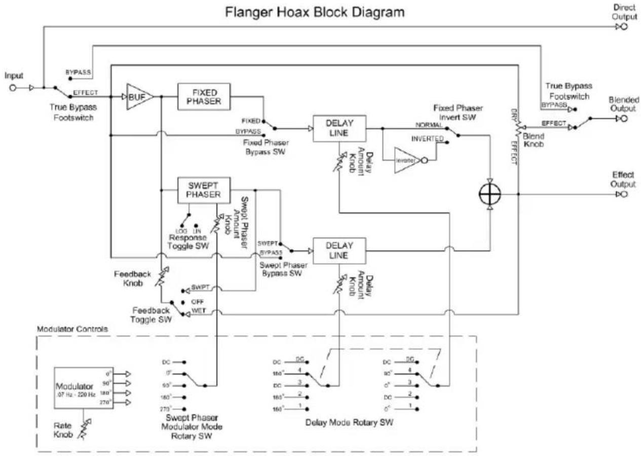
flowchart
graph TD
    A["Input"] --> B["True Bypass Footswitch"]
    B --> C["BUF"]
    C --> D["FIXED PHASER"]
    D --> E["DELAY LINE"]
    E --> F["NORMAL INVERTED"]
    F --> G["Blend Knob"]
    G --> H["Effect Output"]
    I["Modulator Controls"] --> J["Rate Knob"]
    J --> K["Swept Phaser Modulator Mode Rotary SW"]
    K --> L["Response Toggle SW"]
    L --> M["SWPT"]
    M --> N["SWPT Phase Shifter"]
    N --> O["Feedback Toggle SW"]
    O --> P["Feedback Knob"]
    P --> Q["SWPT"]
    Q --> R["SWPT Phase Shifter"]
    R --> S["Response Toggle SW"]
    S --> T["SWPT Phase Shifter"]
    T --> U["Response Toggle SW"]
    U --> V["SWPT Phase Shifter"]
    V --> W["Response Toggle SW"]
    W --> X["SWPT Phase Shifter"]
    X --> Y["Response Toggle SW"]
    Y --> Z["SWPT Phase Shifter"]
    Z --> AA["Response Toggle SW"]
    AA --> AB["SWPT Phase Shifter"]
    AB --> AC["Response Toggle SW"]
    AC --> AD["SWPT Phase Shifter"]
    AD --> AE["Response Toggle SW"]
    AE --> AF["SWPT Phase Shifter"]
    AF --> AG["Response Toggle SW"]
    AG --> AH["SWPT Phase Shifter"]
    AH --> AI["Response Toggle SW"]
    AI --> AJ["SWPT Phase Shifter"]
    AJ --> AK["Response Toggle SW"]
    AK --> AL["SWPT Phase Shifter"]
    AL --> AM["Response Toggle SW"]
    AM --> AN["SWPT Phase Shifter"]
    AN --> AO["Response Toggle SW"]
    AO --> AP["SWPT Phase Shifter"]
    AP --> AQ["Response Toggle SW"]
    AQ --> AR["SWPT Phase Shifter"]
    AR --> AS["Response Toggle SW"]
    AS --> AT["SWPT Phase Shifter"]
    AT --> AU["Response Toggle SW"]
    AU --> AV["SWPT Phase Shifter"]
    AV --> AW["Response Toggle SW"]
    AW --> AX["SWPT Phase Shifter"]
    AX --> AY["Response Toggle SW"]
    AY --> AZ["SWPT Phase Shifter"]
    AZ --> BA["Response Toggle SW"]
    BA --> BB["SWPT Phase Shifter"]
    BB --> BC["Response Toggle SW"]
    BC --> BD["SWPT Phase Shifter"]
    BD --> BE["Response Toggle SW"]
    BE --> BF["SWPT Phase Shifter"]
    BF --> BG["Response Toggle SW"]
    BG --> BH["SWPT Phase Shifter"]
    BH --> BI["Response Toggle SW"]
    BI --> BJ["SWPT Phase Shifter"]
    BJ --> BK["Response Toggle SW"]
    BK --> BL["SWPT Phase Shifter"]
    BL --> BM["Response Toggle SW"]
    BM --> BN["SWPT Phase Shifter"]
    BN --> BO["Response Toggle SW"]
    BO --> BP["SWPT Phase Shifter"]
    BP --> BQ["Response Toggle SW"]
    BQ --> BR["SWPT Phase Shifter"]
    BR --> BS["Response Toggle SW"]
    BS --> BT["SWPT Phase Shifter"]
    BT --> BU["Response Toggle SW"]
    BU --> BV["SWPT Phase Shifter"]
    BV --> BW["Response Toggle SW"]
    BW --> BX["SWPT Phase Shifter"]
    BX --> BY["Response Toggle SW"]
    BY --> BZ["SWPT Phase Shifter"]
    BZ --> CA["Response Toggle SW"]
    CA --> CB["SWPT Phase Shifter"]
    CB --> CC["Response Toggle SW"]
    CC --> CD["SWPT Phase Shifter"]
    CD --> CE["Response Toggle SW"]
    CE --> CF["SWPT Phase Shifter"]
    CF --> CG["Response Toggle SW"]
    CG --> CH["SWPT Phase Shifter"]
    CH --> CI["Response Toggle SW"]
    CI --> CJ["SWPT Phase Shifter"]
    CJ --> CK["Response Toggle SW"]
    CK --> CL["SWPT Phase Shifter"]
    CL --> CM["Response Toggle SW"]
    CM --> CN["SWPT Phase Shifter"]
    CN --> CO["Response Toggle SW"]
    CO --> CP["SWPT Phase Shifter"]
    CP --> CQ["Response Toggle SW"]
    CQ --> CR["SWPT Phase Shifter"]
    CR --> CS["Response Toggle SW"]
    CS --> CT["SWPT Phase Shifter"]
    CT --> CU["Response Toggle SW"]
    CU --> CV["SWPT Phase Shifter"]
    CV --> CW["Response Toggle SW"]
    CW --> CX["SWPT Phase Shifter"]
    CX --> CY["Response Toggle SW"]
    CY --> CZ["SWPT Phase Shifter"]
    CZ --> DA["Response Toggle SW"]
    DA --> DB["SWPT Phase Shifter"]
    DB --> DC
- CONTROLS -
-
BLEND Knob: Mixes between the effect and the dry signal. The counter-clockwise position is all dry, while the clockwise position is all effect. The result of the BLEND Control goes out the BLENDED OUTPUT Jack.
-
FEEDBACK CONTROLS:
FEEDBACK Knob: Sets the amount of signal that is fed back into both phase shift circuits. The counter-clockwise position gives you no feedback; the clockwise position yields maximum feedback.
WET Toggle Switch Position: In the WET position, the wet signal (which is at the EFFECT OUTPUT Jack) is fed back to the phaser circuits.
OFF Toggle Switch Position: All feedback is turned off, no matter where the FEEDBACK knob is set.
SWPT Toggle Switch Position: In the SWPT Position, the output of the Swept Phaser is fed back into the Phaser circuits.
- SWEPT PHASER CONTROL:
AMOUNT Knob: Controls the amount of modulation that sweeps the Swept Phaser. In the counter-clockwise position, there will be no modulation. In the clockwise position you will have maximum modulation. The total phase shift range of the Swept Phaser is 240o to 990o.
RESPONSE Rotary Switch: Determines how the Swept Phaser reacts to the modulation waveform. In LIN Mode, the Phaser reacts in a linear fashion, in LOG mode, it reacts in a logarithmic fashion. In the LOG mode, the Swept Phaser tends to sound more exaggerated.
MODULATOR MODE Rotary Switch: This switch steps through the different phases of the modulation waveform. When used in tandem with Delay modulation, interesting effects arise when the Swept Phaser modulation is in or out of phase with the Delay modulation. The rightmost position of this switch is DC Mode, in which the Swept Phaser becomes a fixed phaser and the amount of phase shift is controlled with the AMOUNT Knob.
4. MODULATOR
RATE Knob: Sets the frequency of the sine wave Modulator. The available frequency range is from 0.07 Hz (14 Seconds) to 220 Hz.
DELAY MODE Switch: Selects between different phase shift combinations for the modulating waveform that sweeps the Fixed Phaser Delay line and the Swept Phaser Delay line:
Fixed Phaser Delay Swept Phaser Delay
Mode 1: 0o Phase Shift 180o Phase Shift
Mode 2: DC 180o Phase Shift
Mode 3: 0o Phase Shift DC
Mode 4: 90o Phase Shift 180o Phase Shift
Mode 5: DC DC
In DC Mode, the delay time is set by the Delay Amount knobs, described in the following section.
- FIXED and SWEPT PHASER Sections: The Flanger Hoax has two independent phase shifter circuits: a FIXED Phaser and SWEPT Phaser. The FIXED Phaser is set to a phase shift of 240o. The SWEPT Phaser varies from 240o to 990o. These two phase shift sections run parallel to each other. The output of each phase shifter goes into its own Delay line circuit. The FIXED and SWEPT Phaser blocks on the right side of the Flanger Hoax have similar controls, though the SWEPT PHASER has additional controls in the SWEPT PHASER CONTROL Block:
DELAY AMOUNT: Controls the amplitude of the sine wave that modulates the delay time or when set to DC mode, sets the delay time. The DELAY MODE Switch in the MODULATOR section chooses between waveform modulation or DC (see the chart above). The range of delay time is 1 ms to 11 ms.
FIXED/BYPASS Toggle Switch: Either bypasses the FIXED Phaser circuit or enables it. When in Bypass, the audio signal will go around the FIXED Phaser circuit and then into its Delay line. When in Fixed mode, the audio signal goes through the FIXED Phaser and then into its Delay line.
SWEPT/BYPASS Toggle Switch: Either bypasses the SWEPT Phaser circuit or enables it. When in Bypass, the audio signal will go around the SWEPT Phaser circuit and then into its Delay line. When in Fixed mode, the audio signal goes through the SWEPT Phaser and then into its Delay line.
INVERT Toggle Switch: This switch inverts the output of the FIXED Phaser block after its Delay line circuitry. By enabling the INVERT Switch, you add 180o more phase shift to the FIXED Phaser output. The SWEPT Phaser does not have an invert switch.
All Electro-Harmonix accessories are compatible and modular. Any combination of units will give you an infinite variety of sounds limited only by your imagination.
- WARRANTY INFORMATION -
Please register online at http://www.ehx.com/product-registration or complete and return the enclosed warranty card within 10 days of purchase. Electro-Harmonix will repair or replace, at its discretion, a product that fails to operate due to defects in materials or workmanship for a period of one year from date of purchase. This applies only to original purchasers who have bought their product from an authorized Electro-Harmonix retailer. Repaired or replaced units will then be warranted for the unexpired portion of the original warranty term.
If you should need to return your unit for service within the warranty period, please contact the appropriate office listed below. Customers outside the regions listed below, please contact EHX Customer Service for information on warranty repairs at info@ehx.com or +1-718-937-8300. USA and Canadian customers: please obtain a Return Authorization Number (RA#) from EHX Customer Service before returning your product. Include with your returned unit: a written description of the problem as well as your name, address, telephone number, e-mail address, and RA#; and a copy of your receipt clearly showing the purchase date.
United States & Canada
EHX CUSTOMER SERVICE ELECTRO-HARMONIX c/o NEW SENSOR CORP. 47-50 33RD STREET LONG ISLAND CITY, NY 11101 Tel: 718-937-8300 Email: info@ehx.com
Europe
JOHN WILLIAMS ELECTRO-HARMONIX UK 13 CWMDONKIN TERRACE SWANSEA SA2 0RQ UNITED KINGDOM Tel: +44 179 247 3258 Email: electroharmonixuk@
This warranty gives a purchaser specific legal rights. A purchaser may have even greater rights depending upon the laws of the jurisdiction within which the product was purchased.
To hear demos on all EHX pedals visit us on the web at www.ehx.com
Email us at info@ehx.com
- FCC COMPLIANCE -
This device complies with part 15 of the FCC Rules. Operation is subject to the following two conditions: (1) This device may not cause harmful interference, and (2) this device must accept any interference received, including interference that may cause undesired operation. If the device is not installed and used in accordance with the instructions, it may cause harmful interference to radio communications and void the user's authority to guarantee the equipment.
Note: This equipment has been tested and found to comply with the limits for a Class B digital device, pursuant to part 15 of the FCC Rules. These limits are designed to provide reasonable protection against harmful interference in a residential installation. This equipment generates, uses and can radiate radio frequency energy and, if not installed and used in accordance with the instructions, may cause harmful interference to radio communications. However, there is no guarantee that interference will not occur in a particular installation. If this equipment does cause harmful interference to radio or television reception, which can be determined by turning the equipment off and on, the user is encouraged to try to correct the interference by one or more of the following m easures:
• Reorient or relocate the receiving antenna.
- Increase the separation between the equipment and receiver.
- Connect the equipment into an outlet on a circuit different from that to which the receiver is connected.
- Consult the dealer or an experienced radio/TV technician for help .
Modifications not expressly approved by the manufacturer could void the user's authority to operate the equipment under FCC rules.
Brand : Electro Harmonix
Model : FLANGER HOAX
Category : Effect pedal