B600 - Heating Blaze - Free user manual and instructions
Find the device manual for free B600 Blaze in PDF.


| Product Type | Electric Heater |
| Brand | Blaze |
| Model | B600 |
| Category | Heating |
| Dimensions (H x W x D) | 45 x 30 x 25 cm |
| Weight | 4.5 kg |
| Power Supply | 220-240 V, 50/60 Hz |
| Power Consumption | 2000 W |
| Heating Technology | Convection with Fan |
| Control Type | Electronic with Remote Control |
| Thermostat | Adjustable, 5-35°C |
| Timer | 1-24 hours |
| Safety Features | Overheat protection, Tip-over switch, Child lock |
| Modes | Fan only, Low heat, High heat |
| Noise Level | ≤ 45 dB |
| Material | Aluminum and ABS plastic |
| Color | White with gray accents |
| Maintenance | Clean air filter monthly with vacuum |
| Accessories Included | Remote control, User manual |
| Warranty | 2 years |
Frequently Asked Questions - B600 Blaze
User questions about B600 Blaze
0 question about this device. Answer the ones you know or ask your own.
Ask a new question about this device
Download the instructions for your Heating in PDF format for free! Find your manual B600 - Blaze and take your electronic device back in hand. On this page are published all the documents necessary for the use of your device. B600 by Blaze.
USER MANUAL B600 Blaze
Operating Instructions
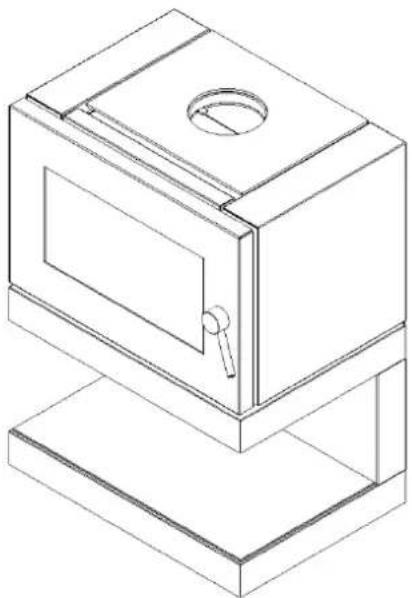
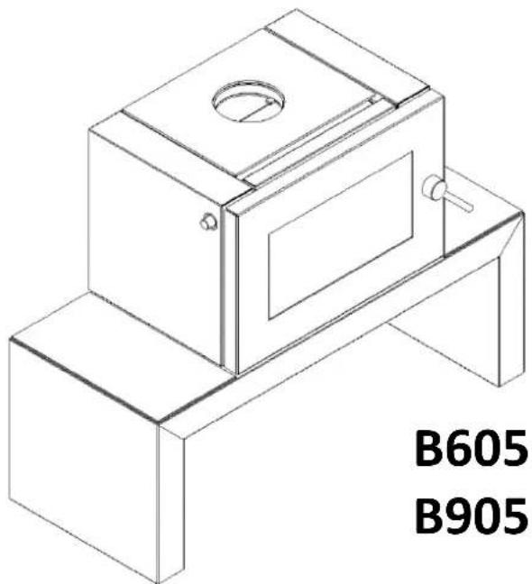
Contemporary and Stylish
natural_image
Isometric line drawing of a two-tiered cabinet or enclosure with a circular vent and handle (no text or symbols)B600
B900
natural_image
Isometric line drawing of a mechanical device with labeled B605 and B905 (no text or symbols on the diagram itself)B605
B905
Keep instructions for future reference

AUSTRALIAN HOME HEATING ASSOCIATION INC.

Glen Dimplex Australia proudly supports the activities of Landcare Australia through its membership of the AHHA
TABLE OF CONTENTS
USER INSTRUCTIONS
1.0 INTRODUCTION 2
2.0 USING APPLIANCE FOR FIRST TIME 3
3.0 RECOMMENDED FUELS 3
4.0 LIGHTING THE FIRE 3
5.0 RUNNING THE APPLIANCE 4
6.0 BURNING TIPS 4
7.0 ASH REMOVAL 5
8.0 FLUE/CHIMNEY FIRE 5
9.0 CLEANING PAINTWORK & GLASS 5
10.0 CLEANING THE FLUE 5
11.0 TROUBLESHOOTING TIPS 6
MAINTENANCE & SERVICING
1.0 REPLACEMENT OF FIREBRICKS 6
2.0 REPLACEMENT OF BAFFLE 7
3.0 REMOVING THE DOOR 7
4.0 ADJUSTING THE DOOR 7
5.0 FITTING A NEW DOOR GLASS 8
6.0 FITTING A NEW DOOR SEAL 8
7.0 DOOR HANDLE ADJUSTMENT 8
8.0 CHANGING FAN CONTROLLER FREQUENCY ..... 9
9.0 REPLACEMENT SPARE PARTS LIST 9
USER INSTRUCTIONS
1. INTRODUCTION
Before use of this appliance please read these instructions fully.
WARNING: ANY MODIFICATION OF THE APPLIANCE THAT HAS NOT BEEN APPROVED IN WRITING BY THE TESTING AUTHORITY IS CONSIDERED AS BREACHING AS/NZS 4013.
WARNING: DO NOT USE FLAMMABLE LIQUIDS OR AEROSOLS TO START OR REKINDLE THE FIRE.
WARNING: DO NOT USE FLAMMABLE LIQUIDS OR AEROSOLS IN THE VICINITY OF THIS APPLIANCE WHEN IT IS OPERATING.
WARNING: DO NOT STORE FUEL WITHIN HEATER INSTALLATION CLEARANCES.
WARNING: WHEN OPERATING THIS APPLIANCE AS AN OPEN FIRE USE A FIRE SCREEN.
WARNING: OPEN AIR CONTROL (AND DAMPER WHEN FITTED) BEFORE OPENING FIRING DOOR.
WARNING: DO NOT BURN WOOD THAT IS PAINTED; OR IS COATED WITH PLASTIC; OR HAS BEEN TREATED WITH ANY CHEMICAL.
CAUTION: THIS APPLIANCE SHOULD NOT BE OPERATED WITH A CRACKED GLASS.
CAUTION: THIS APPLIANCE SHOULD BE MAINTAINED AND OPERATED AT ALL TIMES IN ACCORDANCE WITH THESE INSTRUCTIONS.
The appliance or flue system should not be modified in any way without the written approval of the manufacturer.
Extractor fans or cooker hoods must not be placed in the same room or space as this can cause appliance to emit smoke into the room.
Our cleanburn technology promotes greater efficiency
Air Controls
The Blaze B600/B900 and B605/B905 range wood heaters feature a single air control system. It is designed to introduce oxygen into the base of the fire controlling the rate of combustion of the wood as well as oxygen being drawn into the upper firebox where combustion of the gases occurs.
The air control is operated by sliding the stainless steel cylindrical handle located on the top left side of the heater. Pulled all the way out offers maximum burn rate, while pushed all the way in offers minimum burn rate.
Secondary air holes in the rear of the firebox provide additional oxygen for a more complete combustion of the gases released from the burning wood.
Door Handle
Warning: the door handle may get hot if appliance has been left in High burn setting for an extended period of time. A stainless steel handle extension is supplied with the heater that can be inserted in the end of the door handle when opening and closing if too hot to handle.
Fan
The fan can be used to spread heat around the room quicker, as well as distribute heat into other rooms. It does not have to be on if not required.
Plug the lead from the rear of the heater into a power-point. B600 & B900 models have an override switch on the rear panel next to where the power lead exists the heater base. This must be switched on for the fan to run.
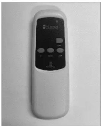
A remote control supplied with the heater is used to turn the fan on and determine the chosen speed.
If the radio frequency used by the remote control interferes with other frequencies in the home such as wireless internet or child monitor refer to "11. Change Fan Controller Frequency" in the Maintenance & Servicing section for details on changing the frequency.
natural_image
White remote control device with black display and control buttons (no visible text or symbols)2. USING APPLIANCE FOR FIRST TIME
- First few times the appliance is lit, it will give off some odorous fumes. This is caused by the paint curing.
- Do not touch the paint work while it is curing otherwise it can leave a permanent mark on the appliance.
- Once the paint has cured it will not re-occur.
- Keep the room well ventilated until these fumes have cleared.
3. RECOMMENDED FUELS
- Burn only seasoned hardwood timber with a moisture content of less than 20%.
- Newly cut wood should be allowed to dry/season for 12 to 18 months before use.
- Wood should be stored in an environment protected from the weather to minimise any potential moisture content.
- For best results, wood should not exceed 270mm in length and 150mm diameter. Any larger and appliance will not operate at its optimum. It is better to burn several smaller pieces of wood than one large single piece.
• Poor quality timber:
- Causes low combustion efficiency
○ Produces poor emissions (smokey)
Results in additional buildup of creosote (soot) in the flue which will then require regular cleaning and may result in a flue fire.
- Do not burn painted, impregnated/treated wood, manufactured board products or pallet wood.
4. LIGHTING THE FIRE
- Place firelighters or paper and dry kindling wood in the base of the firebox.
• Light the paper or firelighters. - Open the air control located on the top left corner of the appliance by pulling out from the appliance.
-
If necessary, leave the door slightly open as the fire establishes and the glass warms to avoid the build-up of condensation.
-
Add larger pieces of wood. Too many logs may smother the fire.
- Close the door.
• Do not leave fire unattended while door is not closed.
5. RUNNING THE APPLIANCE
Maximum Heat Output
- After establishing the fire and loading it with larger pieces of wood, leave it running with the air slide fully open (pulled all the way out).
• This setting will generate maximum heat output. - Running the appliance with the door open will not produce maximum heating in the room as it will draw a lot of already warmed air out of the room.
• Do not overload firebox with fuel. - Note that this setting is not the most energy efficient as some heat is lost up the flue instead of being transferred into the room. However, once fire has established, particulate emissions will be very low, i.e. no smoke, which is good.
- To further maximise heat output, once the firebox is hot turn the fan on to the high speed setting to spread the heat around the room.
Low Heat Output
- The heat output of the appliance can be reduced by closing the air slide which will restrict the oxygen supplied to the fire and slow down the rate at which the wood burns.
- This setting will provide the best energy efficiency as the wood burns for longer. However, if not operated correctly may result in higher particulate emissions.
- Prior to closing the air slide ensure that the fire is burning briskly. This may require opening the air slide fully for 5-10mins before shutting down.
- For the optimum between clean burning, and getting the best in efficiency, from the fully closed position, open the air slide 4-5mm.
- The air slide can be adjusted to any position so desired depending on wanted heat output versus burn time.
- Fan may be turned to low speed setting or off if the heater is putting out sufficient heat without the fan on.
Reload with more wood
1) Open air slide before opening door.
2) Rake / break up any existing coals.
3) Load the wood with the length orientated front to back.
4) Better results will be achieved by loading several smaller pieces of wood than one large piece.
5) Close door with air slide fully open, and leave for minimum of 10 minutes to allow the fresh wood to catch.
6) After 10 or more minutes, the air slide can be adjusted to the desired heat output setting.
6. BURNING TIPS
Fuel Quality
Use wood with a moisture content of less than 20%. Logs should not feel moist or damp, or have moss and fungal growths.
Symptoms related to wet wood:
• Difficulty starting and keeping a fire burning well.
• Smoke and only small flames.
• Dirty glass and/or fire bricks.
• Rapid creosote build-up in the flue/chimney.
- Low heat output.
- Short burn times, and blue/grey smoke from the flue/chimney outlet.
Run appliance at high heat output for a short period each day to avoid large build-up of tars and creosote within the appliance and flue.
Flue Draught
The flue has two main functions:
1) To safely remove smoke, gases and fumes from the appliance.
2) To provide a sufficient amount of draught (suction) in the appliance to ensure the fire keeps burning.
Draught is caused by the rising hot air in the flue when the fire has been lit.
The position, height and size of the flue can affect the performance of the flue draught. Refer to installation guide for details on flue installation.
Factors affecting the flue draught include:
• Insufficient flue height
• Trees or other buildings nearby causing turbulence
• High and gusty winds
• Outside temperature and weather conditions
- Blocked flue
For advice on the correction of persistent flue problems consult your supplier/installer for more detail.
7. ASH REMOVAL
Depending on the type of wood burnt and frequency, the ashes will need removing every 2 to 6 weeks.
Excess ashes should be removed when necessary, placed in a non-combustible container with a tightly fitting lid and moved outdoors immediately to a location clear of combustible materials.
8. FLUE/CHIMNEY FIRE
If a flue/chimney fire occurs:
- Shut air slide control fully to smother the fire
- Do not use the appliance after a flue fire until an accredited installer has assessed the cause and any resultant damage.
9. CLEANING PAINT WORK & GLASS
• The appliance, when cool, can be cleaned with a cloth.
• Over the years, the black paint will fade and can be touched up with Stove Bright metallic black paint.
- To clean the glass, we recommend using a household window cleaner or general purpose cleaner with a soft cloth.
• Do not use abrasive cleaner or scourer pads.
10. CLEANING THE FLUE
- Check inside of flue prior to each season for any build-up of creosote (wood tar). To do this:
- First remove the baffle (refer to "2. Replacement of Baffle" under Maintenance & Servicing section).
○ Using a small mirror and torch hold the mirror on an angle below the flue with the torch shining at it and look for black creosote build-up. If only a fine black powdery layer then that is normal, but if built up layers of creosote can be seen, then the flue needs cleaning.
- Refit the baffle if no cleaning is required.
• To clean the flue:
○ A flue cleaning brush can be purchased from most wood heater retail outlets or large hardware stores.
- The objective is to pull the brush down through the flue.
With the baffle removed, tie a rope to one end of the brush, and drop the rope from the top (outside on top of the roof) down the flue.
- Grab the end of the rope inside the firebox and pull the brush through.
- Check the inside of the flue with the mirror and torch. Repeat if necessary.
Once clean, remove any excess creosote from the firebox and replace the baffle.
- Alternatively, get a flue cleaning service to do the job for you (it's a dirty job).
- Check flue integrity by checking that the 900mm flue sections have not separated at the joins.
11. TROUBLESHOOTING TIPS
Glass in door blackening
This can have several possible causes:
- Burning unseasoned wood — if the wood is too wet, it will cause the glass to blacken.
- Appliance operated at low temperature — after an overnight burn where the air slide control has been fully closed, the glass may have blackened. When the fire is re-stoked and burning on the high heat setting, the blackened glass should self-clean.
- Problems with the flue — insufficient flue draught can cause the glass to blacken. If the flue is too short, not properly insulated, or in a position that results in a downdraught, then there will be insufficient flue draught. Contact the installer should this happen.
Trouble starting the fire
If all ash has been removed from the firebox, then it can upset the supply of air to the base of the fire. It can aid the fire by retaining some ash when cleaning out the firebox.
MAINTENANCE & SERVICING
1. REPLACEMENT OF FIREBRICKS
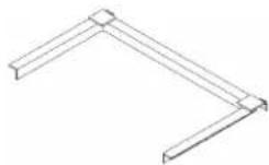
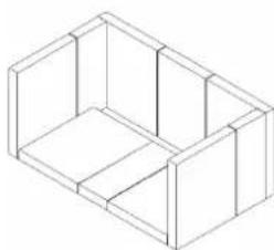
The purpose of the firebricks in the appliance is to increase thermal mass and to guarantee the longevity of the steel firebox. Over time the firebricks may become cracked and crumble away. If so, then they should be replaced soon after.
To replace the firebricks:
1) Move any ash away from the base of the bricks.
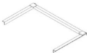
2) Remove the brick retainer and remove the bricks.
3) Replace with new bricks, and refit the retainer which holds the bricks in place.
B600 & B605 – Brick Layout
natural_image
Isometric line drawing of a 3D rectangular box structure (no text or symbols)B900 & B905 – Brick Layout
natural_image
Simple line drawing of a bent L-shaped structure (no text or symbols)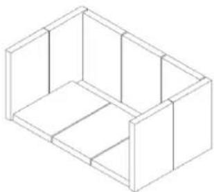
natural_image
Isometric line drawing of a rectangular box with internal compartments (no text or symbols)2. REPLACEMENT OF BAFFLE
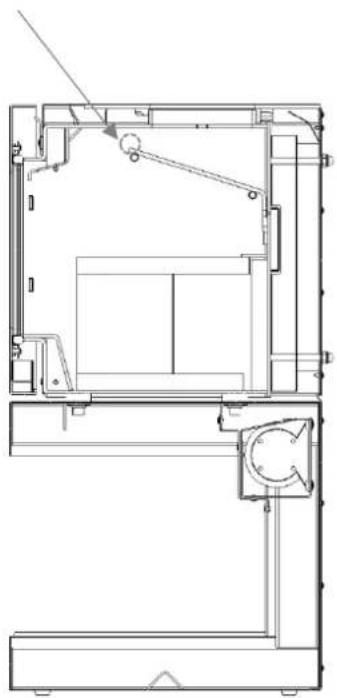
The 6mm thick steel baffle helps to retain the heat in the firebox by lengthening the path of the flame so that they do not go straight up the flue.
Over time, the baffle will begin to sag a little due to the excessive heat. This will not affect the way the fire burns.
Eventually the baffle will burn through (5+ years) and if so will need to be replaced.
To remove the baffle:
1) Lift the baffle up at the back enough to clear the rear support pegs.
2) With the rear of the baffle plate still elevated, slide it forward, up and over the front row of support pegs, and out.
3) Repeat steps 1 to 2 in reverse to replace with the new baffle.
The B900 & B905
baffle plate has an
additional fold in
this location
natural_image
Technical line drawing of a mechanical assembly with no visible text or symbols3. REMOVING THE DOOR
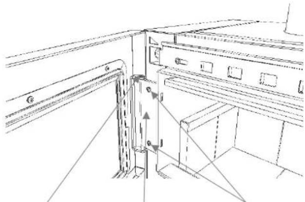
To remove the door:
1) Open the door until it rests against the door stop.
2) Lift the door up and over the top end of the vertical hinge rod.
3) Lower the door and slide off the bottom end of the hinge rod.
natural_image
Technical line drawing of a structural frame with mounting brackets and supports (no text or symbols)Hinge rod Hinge plate Adjusting screws
4. ADJUSTING THE DOOR
Over time the screws securing the door hinge plate to the heater may loosen resulting in the door dropping, i.e. visually appears on slight angle and no longer 100% horizontal. This can result in a poor door seal and unnecessary amounts of oxygen entering the firebox and wood burning too quickly.
To fix this and reposition the door:
1) With the supplied Allen key, loosen the two screws on the hinge plate.
2) With the door 90% closed, slowly lift the bottom right corner of the door until the door appears horizontal.
3) Keeping the door in that position relative to the hinge, open it and tighten the screws until firm.
4) Close the door to 90% again and make any final adjustments up or down by tapping the door on the right hand side until it appears parallel relative to the top and bottom surfaces of the heater.
5) Open door again and tighten screws fully.
5. FITTING A NEW DOOR GLASS
This task may be easier with the door removed from the appliance and laid horizontally on a work-bench.
1) Remove the six M6 size Allen key screws securing the glass retainer to the door with the supplied Allen key.
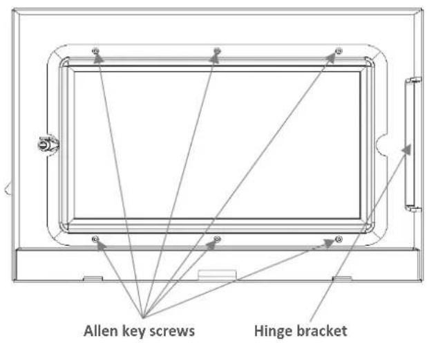
2) Gently lift the glass retainer up and out, taking careful note that the glass may still be intact in the retainer and potentially could fall out.
3) Flip the retainer over, remove the old glass panel.
4) The new door glass panel should have been supplied with a length of adhesive glass seal. Peel back the backing on the tape, and run it along the edges of the glass panel, folding it equally over each side so as to create a padded border around the edge of the glass.
5) Fit the new glass into the glass retainer, relocate the retainer so that all six threads can be seen through the holes, before fastening the six screws.
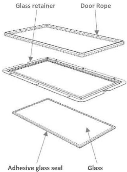
6) Dispose of the old glass in a responsible manner.
6. FITTING A NEW DOOR SEAL
This task may be easier with the door removed from the appliance and laid horizontally on a work-bench.
1) Remove any old seal from the door.
2) Clean out the groove in the door that the seal was bedded in using a flat-end screw driver or equivalent.
3) Run a thin bead of clear roof and gutter silicone along the groove.
4) Starting at one end, press the new door seal into the groove on the door.
5) Refit the door if it has been removed and close.
7. DOOR HANDLE ADJUSTMENT
Over time, the door seal can become compressed resulting in a less than adequate seal between the door and the front edge of the firebox. For example, if the wood burns unusually fast even with the air slide shut, it may mean that there is an air leak around the door.
In this situation, the door seal does not necessarily need replacing rather adjustment of the door handle can tighten the seal.
There are two ways to tighten the door:
1) Adjust door latch bracket – the bracket on the right side of the firebox upon which the door handle latches onto can be gently tapped with a hammer. Alternatively, loosen the two M6 Allen key screws, relocate the bracket into the desired location, and then fasten the two screws. Close the door to test if any improvement in the door closing firmly.
2) Remove washer from door handle assembly:
a) Remove the nut from the door handle shaft inside the door.
b) Remove the latch and remove one washer.
c) Replace the latch and then place the removed washer on the other side.
d) Refit the nut. Do not over tighten otherwise door handle will not turn easily.
If door seal is still not tight enough remove another washer or replace door seal.
The frequency used by the fan remote control can be changed if interferences are experienced in the home.
NOTE: Unplug the power lead before proceeding.
Remote Control Receiver
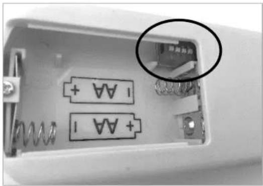
The remote control receiver has four tiny switches on the side, as seen in the photo below. Change the switch setting to something different than current setting. Remember this switch setting as it will need to be replicated on the fan controller.
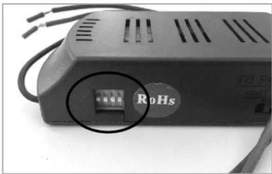
To access the remote control receiver: -
- B600 & B900 Models – located in the base unit, in the rear panel on the left hand side, removed via two screws with a M6 Allen key.
- B605 & B905 – located underneath at the rear of the base unit in a steel cabinet that can be removed via two screws with a M6 Allen key.
Fan Controller
Remove the battery cover and batteries. With a small screwdriver or equivalent, change the switch setting to be the same as that on the remote control receiver.
Replace the batteries and cover, plug in the power lead and test the fan with the different frequency setting. If interferences are still experienced, repeat the steps with another switch setting configuration.
natural_image
Close-up of an electronic device casing showing battery terminals and a close-up of its internal component (no visible text or symbols)9. REPLACEMENT SPARE PARTS LIST
Firebricks
| B600 & B605 | 6 @ 220mm x 175mm x 25mm |
| 1 @ 220mm x 140mm x 25mm | |
| 3 @ 220mm x 85mm x 25mm | |
| B900 & B905 | 10 @ 270mm x 175mm x 25mm |
Baffle Plate
| B600 & B605 | 480mm x 6mm |
| B900 & B905 | 580mm x 6mm |
Ash Deflector
| B600 & B605 | 495mm x 6mm |
| B900 & B905 | 595mm x 6mm |
Door Seal
| B600 & B605 | 1600mm x 16mm round |
| B900 & B905 | 1900mm x 16mm round |
Glass Seal
| B600 & B605 | 1550mm x 19mm x 3mm flat adhesive back |
| B900 & B905 | 1840mm x 19mm x 3mm flat adhesive back |
Brick Retainer
| B600 & B605 | 485mm x 290mm |
| B900 & B905 | 585mm x 350mm |
Door Glass
| B600 & B605 | 483mm x 253mm x 5mm pyro ceramic |
| B900 & B905 | 583mm x 303mm x 5mm pyro ceramic |
Handle Extension, Fan Remote Control, Fan Remote Control Receiver, Fan
GlenDimplex AUSTRALIA
Glen Dimplex Australia Pty Ltd
8 Lakeview Drive,
Scoresby Victoria 3179
Australia
T: 1300 556 816 | F: 1800 058 900
Email: sales@glendimplex.com.au
- Operating Instructions
- TABLE OF CONTENTS
- USER INSTRUCTIONS
- MAINTENANCE & SERVICING
- INTRODUCTION
- Air Controls
- Door Handle
- Fan
- USING APPLIANCE FOR FIRST TIME
- RECOMMENDED FUELS
- LIGHTING THE FIRE
- RUNNING THE APPLIANCE
- Maximum Heat Output
- Low Heat Output
- Reload with more wood
- BURNING TIPS
- Fuel Quality
- Flue Draught
- Factors affecting the flue draught include:
- ASH REMOVAL
- FLUE/CHIMNEY FIRE
- If a flue/chimney fire occurs:
- CLEANING PAINT WORK & GLASS
- CLEANING THE FLUE
- TROUBLESHOOTING TIPS
- Glass in door blackening
- Trouble starting the fire
- REPLACEMENT OF FIREBRICKS
- REPLACEMENT OF BAFFLE
- REMOVING THE DOOR
- ADJUSTING THE DOOR
- FITTING A NEW DOOR GLASS
- FITTING A NEW DOOR SEAL
- DOOR HANDLE ADJUSTMENT
- NOTE: Unplug the power lead before proceeding.
- Remote Control Receiver
- Fan Controller
- REPLACEMENT SPARE PARTS LIST
- GlenDimplex AUSTRALIA
Brand : Blaze
Model : B600
Category : Heating