
MTRTH - Clamping tool Panduit - Free user manual and instructions
Find the device manual for free MTRTH Panduit in PDF.


| Product Type | Cable Tie Mount |
| Material | Nylon 6.6 |
| Color | Natural (White) |
| Temperature Range | -40°C to 85°C |
| Flammability Rating | UL94 V-2 |
| Tensile Strength | 50 lbs (222 N) |
| Max Bundle Diameter | 1.5 in (38 mm) |
| Length | 6.3 in (160 mm) |
| Width | 0.5 in (12.7 mm) |
| Thickness | 0.04 in (1.0 mm) |
| Weight per Unit | 0.02 oz (0.5 g) |
| Mounting Type | Adhesive backed or screw mount |
| Adhesive Type | Acrylic foam tape |
| Operating Humidity | Up to 95% non-condensing |
| UV Resistance | Yes (UV stabilized) |
| RoHS Compliant | Yes |
| Halogen Free | No |
| Standards Met | UL Listed, CSA Certified |
| Installation Tool Required | Optional (Panduit GTH or similar) |
| Package Quantity | 100 pieces per bag |
| Manufacturer | Panduit Corp. |
| Model Number | MTRTH |
| Recyclable | Yes (check local facilities) |
Frequently Asked Questions - MTRTH Panduit
User questions about MTRTH Panduit
0 question about this device. Answer the ones you know or ask your own.
Ask a new question about this device
Download the instructions for your Clamping tool in PDF format for free! Find your manual MTRTH - Panduit and take your electronic device back in hand. On this page are published all the documents necessary for the use of your device. MTRTH by Panduit.
USER MANUAL MTRTH Panduit
MRT and MRS METAL CABLE TIE RETAINED TENSION INSTALLATION TOOLS OPERATION INSTRUCTIONS
The MTRTH Retained Tension Installation Tool is used for installing PANDUIT MRT and MRS Ball Lock Ties in widths of 5/16" (7.9mm) Heavy (H) cross-sections.
The MTRTLS Retained Tension Installation Tool is used for installing PANDUIT MRT and MRS Ball Lock Ties in widths of 3/16" (4.6mm) Standard (S) cross-sections. Included with this tool is an anvil, which can be changed for installing MRT and MRS ties in widths of 1/4" (6.4mm) Light-Heavy (LH) cross-sections.
Changeover Kits are available (listed on Page 7), which allow installation of all three cross-sections of MRT and MRS Ties with either tool.
Note: This tool is not intended for other uses such as cutting or tensioning other types of fastening devices.
SAFETY PRACTICES


ALWAYS wear safety glasses when using this tool.
DO NOT place fingers near cutting blade during tool actuation. Fingers may be pinched or injured by cutter blade.
DO NOT use tool on live electrical sources.
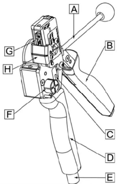
TOOL FEATURES
A. Ball Set / Cutting Handle Lever
B. Upper Handle
C. Tension Indicator Window
D. Tension Handle
E. Adjustment Knob
F. Tensioning Split Mandrel
G. Detent and Setshear Finger
H. Anvil
NOTE: In the interest of higher quality and value, PANDUIT products are continually being improved and updated.
Consequently, pictures may vary from the enclosed product.
Website: www.panduit.com
Technical Support: See back cover for contact information.
MTRTH and MTRTLS TOOL MAINTENANCE
TO INHIBIT CORROSION AND MAINTAIN PERFORMANCE OF THE TOOL, KEEP THE METAL SURFACES COATED WITH A LIGHT OIL (3-IN-ONE® OR EQUIVALENT).
| STRAP SIZE SETTING |  | |
| 3/16" (4.6mm) S | ||
| 1/4" (6.4mm) LH | ||
| 5/16" (7.9mm) H | ||
The tool must be set to the proper tension range based on ties to be installed. Per the above chart, turn the tension knob, so that mark is aligned with correct setting on Tension Setting Label (see above).
MTRTH and MTRTLS OPERATION INSTRUCTIONS
| STEP 1 STEP 2 | |
 | 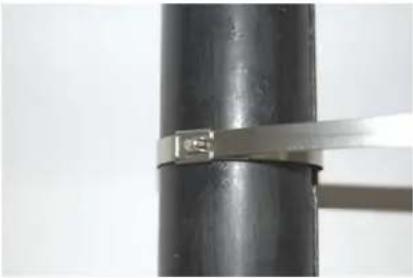 |
| With the tie surrounding the bundle, insert the end of the tie into the head/buckle on the tie. | Draw the tie up as tight as possible by hand. |
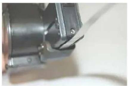
STEP 3

natural_image
Close-up of a mechanical component with a metallic tool inserted, showing no visible text or symbols.
natural_image
Close-up of a mechanical component with metallic parts and a lever (no visible text or symbols)Insert the end of the tie into the tool between Setshear Finger (#1) and Anvil (#2).
STEP 4

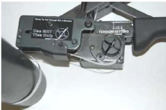
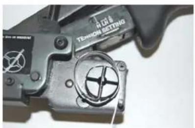
As the tie end is fed through the tool insert the tie end through the Tensioning Split Mandrel. Pull tool tight to bundle.

natural_image
Technical diagram of a mechanical device with circular components and a red wire, no visible text or symbols
CRITICAL: Tool Must Be In-line with the Tie Head

STEP 5

natural_image
Close-up of a mechanical clamp or crimping tool with visible components and no readable text or symbols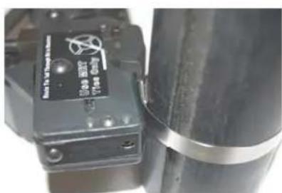
natural_image
Close-up of a black mechanical component with a metallic cylindrical body and a small labeled tag (no readable text or symbols)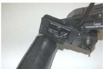
natural_image
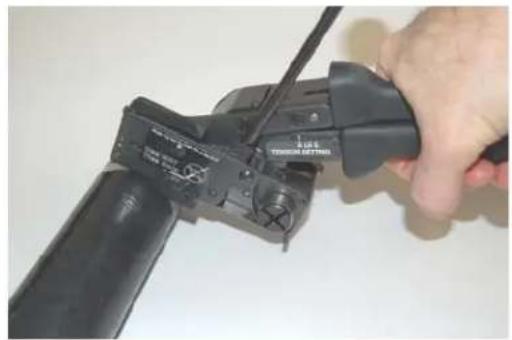
Close-up of a mechanical device with a black lever and adjustment knob (no visible text or symbols)STEP 5 (continued)
natural_image
Close-up of a hand using a handheld electrical crimping tool to adjust or install a device (no visible text or symbols)
natural_image
Close-up of a mechanical assembly with a metallic cylindrical component and connecting wires (no visible text or symbols)Actuate Tension Handle by squeezing the Tension Handle and Upper Handle together.
Continue to do so until the tie is drawn up tight against the bundle.
Continue to squeeze the Tension Handle.
There will be a noticeable click when the tool has reached the preset tension.
The handles will snap together. At this point, the tie is held in the preset tension.
STEP 6

natural_image
Close-up of a hand using a screwdriver to adjust or install a mechanical component (no visible text or symbols)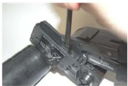
natural_image
Close-up of a hand using a screwdriver to adjust or install a mechanical component (no visible text or symbols)
natural_image
Close-up of a mechanical device with a black cylindrical body and a metallic sensor or connector (no visible text or symbols)Holding the handles together, grasp the Cutter Handle Lever and move it forward.
This action will set ball and cut off the excess tie length flush with the tie head.
STEP 7

natural_image
Close-up of a black cylindrical object with a metallic strap, no visible text or symbolsThis step completes the tie installation. If installed correctly, the tie should be tight on the bundle.

CAUTION: Cut Stainless Steel can have very sharp edges.
STEP 8

natural_image
Close-up of a hand holding a wire cable with a mechanical component (no visible text or symbols)
natural_image
Close-up of a robotic arm gripping a white, coiled cable against a plain background (no text or symbols visible)Remove the wound up excess tie length piece.
TO REPLACE ANVIL
Remove two screws holding Anvil onto the tool. A 3/32" Allen Wrench will be required. The screws may be very tight as they have been installed with Loctite®. Once the screws are removed, slide the Anvil towards the front of the tool and downward away from the tool. Set aside old Anvil. ** Place new Anvil onto bottom of the tool. The Anvil must straddle the two plates and have the slots toward the rear. When the Anvil is slid backwards, the slots must engage the pins. If done correctly, the hole on each side of the Anvil will align with a tapped mounting hole below. Replace the screws applying a drop of Loctite® to each screw. See pictures below.
** IF SETSHEAR FINGER IS TO BE REPLACED AS WELL, NOW IS THE TIME TO REPLACE PER THE INSTRUCTIONS BELOW.
TO REPLACE SETSHEAR FINGER
Remove a single screw holding the Setshear Finger up onto the Sliding Detent Assembly. Use a 1/16" Allen Wrench to remove the screw. The screw may be tight as it has been installed with Loctite®. Once the screw is removed, slide the Setshear Finger toward the front of the tool. This should disengage it from the Sliding Detent Assembly. Pull the Finger down out of the bottom of the tool. Installation is the reverse of these steps. When replacing the Setshear Finger, the notch on the flat surface of the finger must engage the retaining tab on the Sliding Detent Assembly. See pictures below.
WHEN COMPLETE, THE LOCATING SET SCREW ON THE FRONT OF THE TOOL WILL NEED TO BE ADJUSTED PRIOR TO TOOL USE.

SIDE PLATE REMOVED FOR CLARITY

INSTALLATION OF ANVIL OR SETSHEAR FINGER
TO REPLACE ANVIL OR SETSHEAR FINGER:
NOTE: Replace or install Anvil or Setshear Finger per table below.
| MTRTH TOOL MTRTLS TOOL | |||
| HEAVY STANDARD LIGHT HEAVY | |||
| ANVIL MARKS 0 1 2 | |||
| SETSHEARFINGER MARKS | 1 | 2 | 2 |
SETSHEAR FINGER DIFFERENTIATION

ANVIL DIFFERENTIATION

natural_image
Close-up of a metallic rectangular object with a red vertical line and textured surface, no visible text or symbols.Heavy Ties * No Mark - MTRTH Tool -

natural_image
Close-up of a metallic object with a red arrow pointing to a white circular feature, no visible text or symbols.Standard Ties * 1 Mark - MTRTLS Tool -

natural_image
Metallic tray with textured surface and two circular holes, no visible text or symbolsLight Heavy Ties * 2 Marks - MTRTLS Tool -
SETSHEAR FINGER STOP ADJUSTMENT


After each Anvil change, it may be necessary to adjust the Set Screw Stop in the front of the tool. This stop is used for setting how closely the tie tail is cut off. With Cut-Off Handle moved forward, the Set Screw is turned inward or outward to adjust gap between Setshear Finger and Anvil. (CW from tool front moves Finger backwards, CCW moves Finger forward to front of tool.) To set the Set Screw, have Cut-Off Handle all the way forward. Turn the Set Screw CW until the Setshear Finger just touches the Anvil. Back the Set Screw out and place .004" feeler gage. Snug the set screw against the feeler gage. Recheck clearance. The Setshear Finger must not hit or scrape the Anvil. A gap that is too large will cause poor, or no tie cut-offs.
NOTE: SETSHEAR FINGER MUST CLEAR ANVIL.
CHANGEOVER KITS: (Sold Separately)
| KMTRTH | Changeover kit allows for installation of heavy (H) cross-section MRT and MRS style ties in MTRTLS tool. Kit comes complete with one setshear finger (H), one anvil (H), three screws, thread-lock tube and installation instructions. |
| KMTRTLS | Changeover kit allows for installation of standard (S) and light-heavy (LH) cross-section MRT and MRS style ties in MTRTH tool. Kit comes complete with one setshear finger (LS), two anvils (LH and S), three screws, thread-lock tube and installation instructions. |
CONTACT INFORMATION • For Technical Support:
PANDUIT Latino America, Guadalajara, Jalisco, Mexico
Latino America Tel.: 52 (333) 666 2501 • Fax.: 52 (333) 666 2510
Website: www.panduit.com • E-mail: cs-la@panduit.com
PANDUIT Europe, EMEA Headquarters
West World, Westgate, London
England Tel: 44 208 601 7200 • Fax: 44 208 601 7209
Website: www.panduit.com/emea • E-mail: cs-emea@panduit.com
Deutsch Tel: 069 9509 6129 • Fax: 069 9509 6130
Français Tel: 01 4191 8572 • Fax: 01 4191 8573
Spain Tel: 91 377 8107 • Fax: 91 377 8108
PANDUIT Australia, Melbourne (Head Office)
Dandenong, VIC
Aus. Tel: 1-800-PANDUIT / 1-800-726-384 • Fax: 1-800-637-889
Email: cs-aus@panduit.com
PANDUIT United Arab Emmerites
Dubai Internet City, Dubai
Tel: +971 4 3625435 /6 • Fax: +971 4 3908830
E-mail: cs-uae@panduit.com
PANDUIT China, Beijing
Xuanwumen Xidajie Xicheng District
Beijing, China
Tel: 8610 6641 0371 • Fax: 8610 6641 0375
Toll Free Customer Service - North China: 10800 6500 211 • South China: 10800 2650 211
E-mail: cs-ap@panduit.com
PANDUIT Singapore – Sales Office
Singapore, Republic of Singapore
Tel: 65 6379 6700 • Fax: 65 6379 6759
E-mail: cs-ap@panduit.com
- MRT and MRS METAL CABLE TIE RETAINED TENSION INSTALLATION TOOLS OPERATION INSTRUCTIONS
- MTRTH and MTRTLS TOOL MAINTENANCE
- MTRTH and MTRTLS OPERATION INSTRUCTIONS
- TO REPLACE ANVIL
- TO REPLACE SETSHEAR FINGER
- INSTALLATION OF ANVIL OR SETSHEAR FINGER
- TO REPLACE ANVIL OR SETSHEAR FINGER:
- SETSHEAR FINGER STOP ADJUSTMENT
- NOTE: SETSHEAR FINGER MUST CLEAR ANVIL.
- CONTACT INFORMATION • For Technical Support:
Brand : Panduit
Model : MTRTH
Category : Clamping tool