
FVM4X6000BL - Home Fan Arcoaire - Free user manual and instructions
Find the device manual for free FVM4X6000BL Arcoaire in PDF.


| Product Type | Whole House Fan |
| Model | FVM4X6000BL |
| Brand | Arcoaire |
| Dimensions (Approx.) | 24 x 24 x 12 inches (H x W x D) |
| Weight | 30 lbs (13.6 kg) |
| Power Supply | 120V AC, 60 Hz |
| Amperage | 2.5 A |
| Airflow Capacity | Up to 6000 CFM (cubic feet per minute) |
| Speed Settings | Variable speed control |
| Noise Level | Low 55 dB to high 70 dB |
| Installation Type | Ceiling or attic mount |
| Duct Connection | Round, 10-inch diameter |
| Main Features | Thermostat control, manual on/off, energy efficient cooling |
| Material | Galvanized steel housing, aluminum blades |
| Maintenance | Clean blades and motor annually; lubricate motor bearings |
| Safety Features | Thermal overload protection, safety grille |
| Certifications | ETL listed, HVI certified |
| Warranty | 1 year limited |
| Repairability | Replaceable motor and blades; user serviceable |
Frequently Asked Questions - FVM4X6000BL Arcoaire
User questions about FVM4X6000BL Arcoaire
0 question about this device. Answer the ones you know or ask your own.
Ask a new question about this device
Download the instructions for your Home Fan in PDF format for free! Find your manual FVM4X6000BL - Arcoaire and take your electronic device back in hand. On this page are published all the documents necessary for the use of your device. FVM4X6000BL by Arcoaire.
USER MANUAL FVM4X6000BL Arcoaire
INSTALLATION INSTRUCTIONS
Fan Coils
FVM4X "B" Series
These instructions must be read and understood completely before attempting installation.
Safety Labeling and Signal Words
DANGER, WARNING, CAUTION, and NOTE
The signal words DANGER, WARNING, CAUTION, and NOTE are used to identify levels of hazard seriousness. The signal word DANGER is only used on product labels to signify an immediate hazard. The signal words WARNING, CAUTION, and NOTE will be used on product labels and throughout this manual and other manuals that may apply to the product.
DANGER – Immediate hazards which will result in severe personal injury or death.
WARNING – Hazards or unsafe practices which could result in severe personal injury or death.
CAUTION – Hazards or unsafe practices which may result in minor personal injury or product or property damage.
NOTE - Used to highlight suggestions which will result in enhanced installation, reliability, or operation.
Signal Words in Manuals
The signal word WARNING is used throughout this manual in the following manner:

WARNING
The signal word CAUTION is used throughout this manual in the following manner:

CAUTION
Signal Words on Product Labeling
Signal words are used in combination with colors and/or pictures on product labels.
TABLE OF CONTENTS
Introduction 2.
Location 2.
Heater Packages 3.
Position Unit 3-7
Air Ducts 7....
Electrical Connections 8-10
Refrigerant Tubing 10
Refrigerant Metering Device 10
Condensate Drains 11
Blower Motor - CFM 12 - 13
Accessories 14
Sequence of Operation 15
Wiring Diagram 16
Fan Coil Airflow 17 - 19
ECM Motor and Control 19
Troubleshooting ECM Motor and Controls .... 19 - 21
Start-up Procedure 22
Care and Maintenance 22
R-410A Quick Reference Guide 23

WARNING
DEATH, PERSONAL INJURY, AND/OR PROPERTY DAMAGE HAZARD
Failure to carefully read and follow this warning could result in equipment malfunction, property damage, personal injury and/or death.
Installation or repairs made by unqualified persons could result in equipment malfunction, property damage, personal injury and/or death.
The information contained in this manual is intended for use by a qualified service technician familiar with safety procedures and equipped with the proper tools and test instruments.
Follow all safety codes. Wear safety glasses, protective clothing, and work gloves. Use quenching cloth for brazing operations. Have fire extinguisher available.
Installation must conform with local building codes and with the National Electrical Code NFPA70 current edition.
In Canada, refer to current editions of the Canadian electrical code CSA22.1.
INTRODUCTION
Models FVM4X are designed for maximum flexibility and can be used for upflow, horizontal left or right, and downflow applications (accessory kit required for downflow or horizontal right).
These units leave the factory compliant with low leak requirements of less than 2% cabinet leakage rate at 0.5 inches W.C. and 1.4% cabinet leakage rate at 0.5 inches W.C. when tested in accordance with ASHRAE 193 standard. Because of this, the units need special attention in the condensate pan and drain connection area and when brazing tubing.
LOCATION
Select the best position which suits the installation site conditions. The location should provide adequate structural support, space in the front of the unit for service access, clearance for return air and supply duct connections, space for refrigerant piping connections and condensate drain line connections. If heaters are being installed make sure adequate clearance is maintained from supply duct work. Refer to Clearances below.
NOTE: If the door gasket is damaged or missing, the unit may not meet the ASHRAE 193 standard for cabinet air leakage. Contact your supplier and order kit #1191140.
Nuisance sweating may occur if the unit is installed in a high humidity environment with low airflow. On these installations a wrap of 2" (51 mm) fiberglass insulation with a vapor barrier is recommended.
NOTE: Internal filter can be accessed from separate filter door. If the filter can NOT be easily accessed, a remote
HEATER PACKAGES
Factory approved, field installed, UL listed heater packages are available from the equipment supplier. See unit rating plate for a list of factory approved heaters.
POSITION UNIT
Unit can stand or lie on floor, or hang from ceiling or wall. Allow space for wiring, piping, and servicing unit.

CAUTION
PROPERTY DAMAGE HAZARD
Failure to follow this caution may result in property damage.
A field fabricated auxiliary drain pan, with a separate drain is REQUIRED for all installations over a finished living space or in any area that may be damaged by overflow from a restricted main drain pan. In some localities, local codes require an auxiliary drain pan for ANY horizontal installation.
Four fan coil sizes will combine with various outdoor unit sizes to offer systems ranging from 11/2 – 5 tons (18,000 – 60,000 BTUH) nominal cooling capacity.
All models have a factory installed and appropriately sized hard shut-off TXV metering device.
Factory–authorized, field–installed electric heater packages are available in sizes 5 kW through 30 kW. See Product Specification literature for available accessory kits.
filter is recommended. Refer to ACCA Manual D for remote filter sizing.

WARNING
FIRE HAZARD
Failure to maintain proper clearances could result in personal injury, death, and/or property damage.
When heaters are installed, maintain clearances from combustible materials as specified on unit rating plate. Do not use plastic lined or combustible flexible ducting within 36" (914.4) of the supply end of the fan coil.
| REQUIRED CLEARANCES - ALL MODELS (inches) | ||
| No Heaters | All Sides 0 | |
| From Supply Duct 0 | ||
| With Heaters | All Sides 0 | |
| From First 3 feet of Supply Duct to Combustibles | 1 | |
| From Supply Duct to Combustibles after 3 feet | 0 | |
Heaters that are not factory approved could cause damage which would not be covered under the equipment warranty.
A. UPFLOW INSTALLATION
If return air is to be ducted through a floor, install duct flush with floor. Set unit on floor over opening.
Side return is a field option on slope coil models. Cut opening per dimensions shown in Figure 2. A field-supplied bottom closure is required.

CAUTION
Failure to follow this caution may result in personal injury.
Sheet metal parts may have sharp edges or burrs. Use care and wear appropriate protective clothing and gloves when handling parts.
Figure 2 Slope Coil Unit in Upflow Application

Figure 3 Modular Unit Assembly

B. MODULAR UNITS
FVM fan coil sizes 4800 and 6000 are two-piece modular units. This allows for modular units to be disassembled and components moved separately to installation area for reassembly. This process accommodates small scuttle holes and limiting entrances to installation sites (refer to Figure 3).
C. HORIZONTAL INSTALLATION
Unit must NOT be installed with access panels facing up or down. Access panels must only face to the side.
FVM models are factory built for horizontal left installation (refer to Figure 4 and Figure 5). They can be field converted to horizontal right (accessory Gasket Kit required - EBAC01GSK).
NOTE: When suspending unit from ceiling, dimples in casing indicate suitable location of screws for mounting metal support straps (refer to Figure 4).
NOTE: For optimum condensate drainage performance in horizontal installations, unit should be leveled along its length and width.
Figure 4 Slope Coil In Horizontal Left Application (FVM factory configuration)
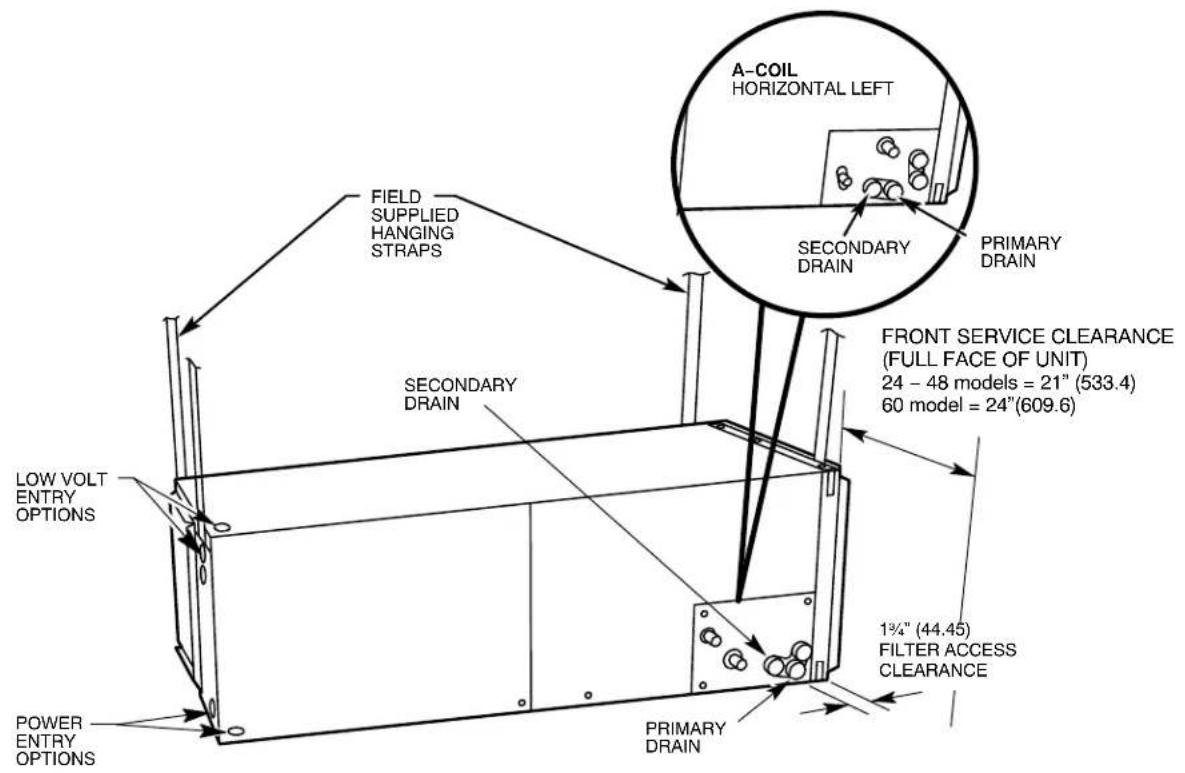
Figure 5 A-Coil in Horizontal Left Application (FVM factory configuration)

Horizontal Right Conversion of Units With Slope Coils
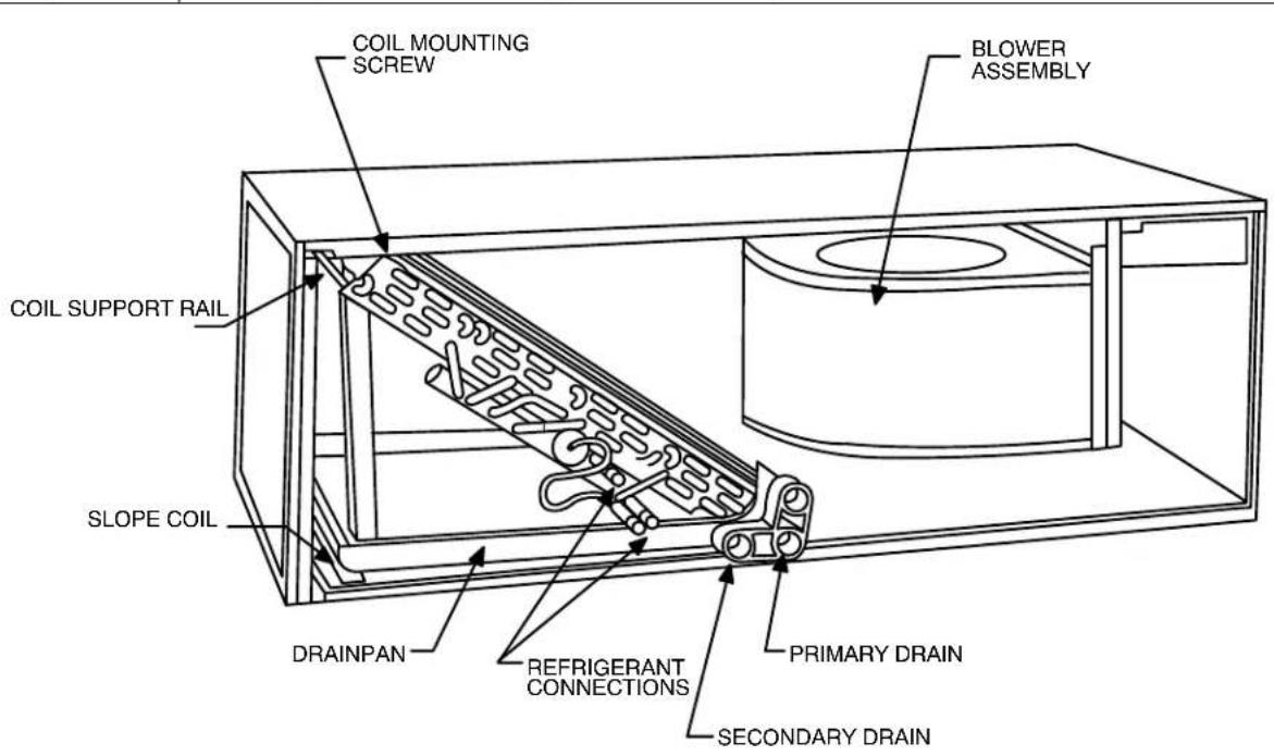
- Remove blower and coil access panel and fitting panel (refer to Figure 6).
-
Remove coil mounting screw securing coil assembly to right side casing flange.
-
Remove coil assembly.
- Lay fan coil unit on its right side and reinstall coil assembly with condensate pan down (refer to Figure 6).
-
Attach coil to casing flange using coil mounting screw previously removed.
-
Make sure the pan cap in the fitting door is properly seated on the fitting door to retain the low air leak rating of the unit.
Figure 6 Horizontal Right Conversion Applications – Slope Coil
-
Add gaskets from the Gasket Accessory Kit - EBAC01GSK.
-
Align holes with tubing connections and condensate pan connections, and reinstall access panels and fitting panel. Make sure liquid and suction tube grommets are in place to prevent air leaks and cabinet sweating.
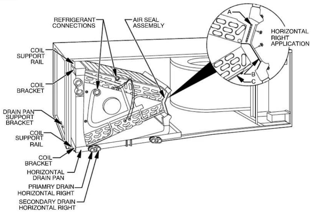
Figure 7 Conversion for Horizontal Right Applications - A-Coil
Horizontal Right Conversion of Units With A-Coils
- Remove blower and coil access panel and fitting panel (refer to Figure 7).
- Remove metal clip securing fitting panel to condensate pan. Remove fitting panel.
- Remove two (2) snap-in clips securing A-coil in unit.
- Slide coil and pan assembly out of unit.
- Remove horizontal drain pan support bracket from coil support rail on left side of unit and reinstall on coil support rail on right side of unit.
- Convert air-seal assembly for horizontal right.
a. Remove air-seal assembly from coil by removing four (4) screws (refer to Figure 7).
b. Remove air splitter (B) from coil seal assembly by removing three (3) screws. (factory-shipped inset.)
c. Remove filler plate (A) and install air splitter (B) in place of filler plate.
d. Install filler plate (A) as shown in horizontal right application.
e. Remove condensate troughs (C) and install on opposite tube sheets.
f. Install hose onto plastic spout.
- Install horizontal pan on right side of coil assembly.
- Slide coil assembly into casing. Be sure coil bracket on each corner of vertical pan engages coil support rails.
- Reinstall two (2) snap-in clips to correctly position and secure coil assembly in unit. Be sure clip with large offsets is used on right side of unit to secure horizontal pan.
- Remove two (2) oval fitting caps from left side of the coil, access panel, and fitting panel.
- Remove insulation knockouts on right side of coil access panel
- Remove two (2) oval coil access panel plugs and reinstall into holes on left side of coil access panel and fitting panel.
- Install condensate pan fitting caps (from Step 10) in the right side of the coil door making sure that the cap snaps and seats cleanly on the back side of the coil door. Make sure no insulation interferes with seating of the cap.
- Reinstall access fitting panels, aligning holes with tubing connections and condensate pan connections. Be sure to reinstall metal clip between fitting panel and vertical condensate pan.
- After brazing, make sure liquid and suction tube grommets are in place to prevent air leaks and cabinet sweating.
F. DOWNFLOW INSTALLATION

CAUTION
PRODUCT OR PROPERTY DAMAGE HAZARD
Failure to follow this caution may result in product or property damage
The conversion of the fan coil to downflow requires special procedures for the condensate drains on both A-coil and Slope-coil units. The vertical drains have an overflow hole between the primary and secondary drain holes. This hole is plugged for all applications except downflow, and must be used for downflow.
Failure to follow instructions could result in personal injury or product and property damage.
In this application, field conversion of the evaporator coil is required using accessory Downflow Kit along with an accessory Base Kit. Set unit on floor over opening and use 1/8" (3.175) to 1/4" (6.35) thick fireproof resilient gasket between duct, unit, and floor. Refer to installation instructions packaged with accessory kit. See Product Specification literature for kit part numbers.
During the conversion process, removed the plastic cap covering the vertical drains only and discard.
Remove the plug from the overflow hole and discard.
At completion of the downflow installation, caulk around the vertical pan fitting to door joint to retain low air leak performance of the unit.
NOTE: Gasket kit number (EBAC01GSK) is also required for all downflow applications to maintain low air leak/low sweat performance.
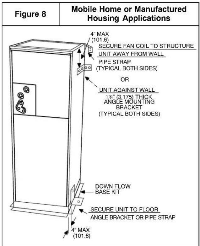
G. MANUFACTURED HOUSING AND MOBILE HOME APPLICATIONS
- Fan coil unit must be secured to the structure using field-supplied hardware.
- Allow a minimum of 24" (609.6) clearance from access panels.
- Recommended method of securing for typical applications:
a. If fan coil is away from wall, attach pipe strap to top of fan coil using No. 10 self tapping screws. Angle strap down and away from back of fan coil, remove all slack, and fasten to wall stud of structure using 5/16" (7.9375) lag screws. Typical both sides of fan coil.
b. If fan coil is against wall, secure fan coil to wall stud using 1/8" (3.175) wide right-angle brackets. Attach brackets to fan coil using No. 10 self tapping screws and to wall stud using 5/16" (7.9375) lag screws (refer to Figure 8).
AIR DUCTS
Connect supply-air duct over the outside of 3/4 (19.05) flanges provided on supply-air opening. Secure duct to flange using proper fasteners for type of duct used, and seal duct-to-unit joint.
Duct connections flanges are provided on unit air discharge connection.
When using FVM units with 20kW, 24kW, and 30kW electric heaters, maintain a 1" (25.4) clearance from combustible materials to discharge plenum and ductwork for a distance of 36" (914.4) from unit. Use accessory downflow base to maintain proper clearance on downflow installations.
It is a recommendation, but not a requirement, to use flexible connections between ductwork and unit to prevent transmission of vibration. When electric heater is installed, use heat-resistant material for flexible connector between duct work and unit at discharge connection. Duct work passing through unconditioned space must be insulated and covered with vapor barrier.
Duct work Acoustical Treatment
Metal duct systems that do not have a 90 degree elbow and 10 feet of main duct before first branch takeoff may require internal acoustical insulation lining. As an alternative, fibrous duct work may be used if constructed and installed in accordance with the latest edition of SMACNA construction standard on fibrous glass ducts. Both acoustical lining and fibrous duct work shall comply with National Fire Protection Association as tested by UL Standard 181 for Class 1 air ducts.
ELECTRICAL CONNECTIONS
On units with a factory installed disconnect with pull-out removed, service and maintenance can be safely performed on only the load side of the control package.
NOTE: Before proceeding with electrical connections, make certain that supply voltage, frequency, phase, and circuit ampacity are as specified on the unit rating plate.
See unit wiring label for proper field high and low voltage wiring. Make all electrical connections in accordance with the NEC and any local codes or ordinances that may apply. Use copper wire only. The unit must have a separate branch electric circuit with a field-supplied disconnect switch located within sight from, and readily accessible from the unit.

WARNING
ELECTRICAL SHOCK or UNIT DAMAGE HAZARD
Failure to follow this warning could result in personal injury or death.
Turn off the main (remote) disconnect device before working on incoming (field) wiring.
Incoming (field) wires on the line side of the disconnect found in the fan coil unit remain live, even when the pull-out is removed. Service and maintenance to incoming (field) wiring cannot be performed until the main disconnect switch (remote to the unit) is turned off.

WARNING
ELECTRICAL SHOCK or UNIT DAMAGE HAZARD
Failure to follow this warning could result in personal injury, death, and/or unit damage.
If a disconnect switch is to be mounted on unit, select a location where drill and fasteners will not contact electrical or refrigeration components.
A. LINE VOLTAGE CONNECTIONS
If unit contains an electric heater, remove and discard power plug from fan coil and connect male plug from heater to female plug from unit wiring harness. (Refer to Electric Heater Installation Instructions.) For units without electric heat:
- Connect 208/230V power leads from field disconnect to yellow and black stripped leads.
- Connect ground wire to unit ground lug.
Check all factory wiring per unit wiring diagram and inspect factory wiring connections to be sure none were loosened in transit or installation.
B. 24V CONTROL SYSTEM
Control System Connections to Fan Control Board
Refer to unit wiring instructions for recommended wiring procedures. Use 18 AWG color-coded, insulated (35 °C minimum) wires to make the low-voltage connections between the thermostat, the unit, and the outdoor equipment. If the thermostat is located more than 100 feet from the unit (as measured along the low voltage wire), use 16 AWG color-coded, insulated (35 °C minimum) wire. Fan Control Board is circuited for single-stage heater operation. When additional heater staging is desired using outdoor thermostats of Heat Staging, remove Jumper J2 on Fan Control Board to enable staging.
All wiring must be NEC Class 1 and must be separated from incoming power leads. Refer to outdoor unit wiring instructions for additional wiring recommendations.
Connect low-voltage leads to thermostat and outdoor unit (refer to Figure 9, Figure 10, Figure 11, Figure 12).
C. HEAT STAGING
Heat Staging Option
Heat Staging of the electric heat package is possible when the FVM is installed as a part of a single-stage heat pump system using a two-stage programmable thermostat, or capable zoning control and and one (1) of the following electric heat packages:
Relay heaters EHK10AKN, EHK10AKB, EHK15AK(F,B), EHK18AHN, EHK20AK(F,B) EHK25AHCF, or EHK30AHCF.
Complete system low-voltage wiring as shown in Figure 9, Figure 10, Figure 11, Figure 12.
NOTE: Where local codes require thermostat wiring be routed through conduit or raceways, splices can be made inside the fan coil unit. All wiring must be NEC Class 1 and must be separated from incoming power leads.
A factory–authorized disconnect kit is available for installation of 5 kW through 10 kW applications. When electric heat package with circuit breakers are installed, the circuit breaker can be used as a disconnect.
D. MANUFACTURED HOUSING
In manufactured housing applications, the Code of Federal Regulations, Title 24, Chapter XX, Part 3280.714 requires that supplemental electric heat be locked out at outdoor temperatures above 40 °F. except for a heat pump defrost cycle. In some applications, an outdoor thermostat may be required. Refer to thermostat instructions for details.
![graph TD A["INDOOR CONTROL"] --> B["HEAT STAGE 2"] A --> C["N/A"] A --> D["HEAT STAGE 1"] A --> E["COOL STAGE 1"] A --> F["FAN"] A --> G["24 VAC HOT"] A --> H["DEHUMIDIFY"] A --> I["24 VAC COMM"] A --> J["HUMIDIFY"] A --> K["N/A"] A --> L["OUTDOOR"] M["FAN COIL"] --> N["W2"] M --> O["Y1"] M --> P["W…](/content/2026/05/981687/images/2aa5dd3279732d93728595ac2b91581faed882f9e3f14fe812230855bd5ca83b.jpg)
![graph TD A["INDOOR CONTROL FAN COIL"] --> B["RVS COOLING"] A --> C["HEAT STAGE 3"] A --> D["HEAT STAGE 2"] A --> E["FAN"] A --> F["24 VAC HOT"] A --> G["DEHUMIDIFY"] A --> H["24 VAC COMM"] A --> I["HUMIDIFY"] A --> J["RVS HEATING"] A --> K["OUTDOOR"] B --> L["O"] C --> M["W2"] D --> N["W1"] E --> O[…](/content/2026/05/981687/images/2455e035326bb6b12cbb7a9e53861919ab874b9b2fb45d387a54ffe0c9335711.jpg)
![graph TD A["INDOOR CONTROL"] --> B["FAN COIL"] B --> C["OUTDOOR"] subgraph INDUSTRY D["HEAT STAGE 2"] --> E["O/W2"] F["HEAT STAGE 1"] --> G["W/W1"] H["COOL STAGE 1"] --> I["Y1/W2"] J["COOL STAGE 2"] --> K["Y/Y2"] L["FAN"] --> M["G"] N["24 VAC HOT"] --> O["R"] P["DEHUMIDIFY"] --> Q["DHUM"] R["24 VAC…](/content/2026/05/981687/images/1c77743f8365929c8826a204b8373d4523dd876d799e83eaea83fbd0211e4c7e.jpg)
![graph TD A["INDOOR CONTROL"] --> B["FAN COIL"] B --> C["OUTDOOR"] subgraph indoor control D["RVS COOLING"] --> E["O/W2"] F["HEAT/COOL STAGE 1"] --> G["Y1/W2"] H["HEAT STAGE 3"] --> I["W/W1"] J["HEAT/COOL STAGE 2"] --> K["Y/Y2"] L["FAN"] --> M["G"] N["24 VAC HOT"] --> O["R"] P["DEHUMIDIFY"] --> Q["DH…](/content/2026/05/981687/images/acdf5164ef49490e634985c1b4d8e4c2b3acc84903e55c523303258fdd33059c.jpg)
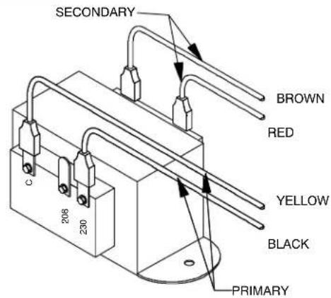
Figure 13 Transformer Connections
E. TRANSFORMER INFORMATION
Transformer is factory wired for 230V operation. For 208V applications, disconnect the black wire from the 230V terminal on transformer and connect it to the 208V terminal (refer to Figure 13).
The secondary circuit of transformer is protected by a 5 amp fuse mounted on Fan Control Board.
REFRIGERANT TUBING
Use accessory tubing package or field-supplied tubing of refrigerant grade. Insulate entire suction tube if field-supplied tubing is used. Tubing package has an insulated suction. Do not use damaged, dirty, or contaminated tubing because it may plug refrigerant flow control device.
Always evacuate coil and field-supplied tubing to 500 microns before opening outdoor unit service valve.

CAUTION
PRODUCT DAMAGE HAZARD
Failure to follow this caution may result in product damage.
Braze with Sil-Fos or Phos-copper alloy on copper-to-copper joints and wrap a wet cloth around rear of fitting to prevent damage to TXV.
REFRIGERANT METERING DEVICE
FVM fan coils have a factory installed hard shut-off TXV designed only for use with R-410A refrigerants. Use only with outdoor units designed for corresponding refrigerants.
TXV is factory set and not field adjustable.
F. GROUND CONNECTIONS
NOTE: Use UL listed conduit and conduit connectors for connecting supply wire(s) to unit to obtain proper grounding. Grounding may also be accomplished by using grounding lugs provided in control box. Use or dual or multiple supply circuits will require grounding of each circuit to ground lugs provided on unit and heaters.

WARNING
ELECTRICAL SHOCK HAZARD
Failure to establish uninterrupted or unbroken ground could result in personal injury and/or death.
According to NEC, ANSI/NFPA 70, and local codes, the cabinet must have an uninterrupted or unbroken ground in order to minimize potential for personal injury or death if an electrical fault should occur. The ground may consist of electrical wire or metal conduit when installed in accordance with existing electrical codes. If conduit connection uses reducing washers, a separate ground wire must be used.
Size and install refrigerant lines according to information provided with outdoor unit. Route refrigerant lines to the fan coil in a manner that will not obstruct service access to the unit or removal of the filter.
- Cut tubing to correct length.
- Hold coil stubs steady to avoid bending or distorting.
- Fit refrigerant lines into coil stubs. Insert tube into sweat connection on unit until it bottoms.
- Wrap TXV and nearby tubing with a heat-sinking material such as a wet cloth.
- Wrap a heat sinking material such as a wet cloth behind braze joints.
- Braze connection using a silver bearing or non-silver brazing materials (Sil-Fos or Phos-copper alloy). Do not use solder (matrices which melt below 800°F). Consult local code requirements.
- After brazing, allow joints to cool. Evacuate coil and tubing system to 500 microns using deep vacuum method.

CAUTION
PRODUCT DAMAGE HAZARD
Failure to follow this caution may result in product damage.
This Fan Coil has a hard shut-off TXV metering device. A compressor Hard Start Kit is REQUIRED in all applications where the matching outdoor unit has a single-phase reciprocating compressor.
CONDENSATE DRAINS
Units are provided with primary and secondary 3/4 " NPT drain connections. Refer to Figure 2 though Figure 7 to identify the primary and secondary locations. To prevent property damage and achieve optimum drainage performance, BOTH primary and secondary drain lines should be installed and include properly sized condensate traps (refer to Figure 14). Factory approved condensate traps are available (accessory part number EBAC01CTK).
To connect drain lines, the drain connection knock-outs must be removed. Use a knife to start the opening near the tab and using pliers, pull the tab to remove the knock-out. Clean the edge of the opening if necessary. After drain fittings are installed, caulk the seam between the fitting and the cover to retain the low leak rating of the unit.
It is recommended the PVC fittings be used on the plastic condensate pan. Do not over-tighten. Finger-tighten plus 1½ turns. Use pipe dope, to ensure proper seal.
Install traps in the condensate lines as close to the coil as possible (refer to Figure 16), but avoid blocking filter access panel.
Install drain lines below the bottom of the drain pan and pitch the drain lines down from the coil at least 1/4 inch per foot of run. Horizontal runs over 15 feet long must also have an anti-siphon air vents (stand pipes), installed ahead of the horizontal runs. Extremely long horizontal runs may require oversized drain lines to eliminate air trapping.
Route primary drain line to the outside or to a floor drain. Check local codes before connecting to a waste (sewer) line.
Route the secondary drain line to a place in compliance with local installation codes where it will be noticed when unit is operational. Condensate flowing from secondary (overflow) drain indicates a plugged primary drain – unit requires service or water damage will occur.
Prime all traps, test for leaks, and insulate in areas where sweating of the traps and drain lines could potentially cause water damage. Consult local codes for additional requirements or precautions.
If a gravity drain cannot be used, install a condensate pump. Install the pump as close to the indoor section as possible.

CAUTION
PRODUCT or PROPERTY DAMAGE HAZARD
Failure to follow this caution may result in product or property damage.
Use only full size P-traps in the condensate line (refer to Figure 14). Shallow, running traps are inadequate and DO NOT allow proper condensate drainage (refer to Figure 15).
Figure 14 Recommended Condensate Trap

Figure 15 Insufficient Condensate Trap
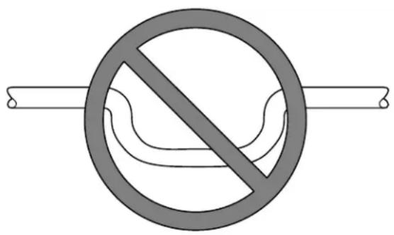
DO NOT USE SHALLOW RUNNING TRAPS!
Figure 16 Condensate Drain
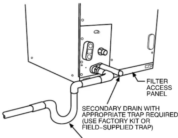
PRIMARY TRAP REQUIRED (USE FACTORY KIT OR FIELD-SUPPLIED TRAP OF PROPER DEPTH. STANDARD P-TRAPS ARE NOT SUFFICIENT. SEE FIGURE OF RECOMMENDED CONDENSATE TRAP)
BLOWER MOTOR - CFM
FAN CONTROL BOARD CONFIGURATION TAPS
Fan Control Board taps are used by the installer to configure a system. The ECM motor uses the selected taps to modify its operation to a pre-programmed table of airflows (Refer to Table 2 and Table 3). Airflows are based on system size or mode of operation and those airflows are modified in response to other inputs such as the need for de-humidification. (Refer to Figure 17 and Figure 18).
FVM fan coils must be configured to operate properly with system components with which it is installed. To successfully configure a basic system (see information printed on circuit board label located next to select pins), move the 6 select wires to the pins which match the components used.
Figure 17 Fan Control Board

A. AUXILIARY HEAT KW/CFM
Installer must select the auxiliary heat airflow approved for application with kW size heater installed. If no heater is installed, this step can be skipped. (Refer to Figure 17, A)
The select pins are marked A, B, C, D. Heater kW ranges corresponding to each letter are listed in a chart on the unit wiring diagram. Refer to the unit wiring diagram and select the pin for the heater size being used (example wiring diagram in Figure 21).
The airflow must be greater than the minimum CFM for electric heater application with the size system installed for safe and continuous operation. (Refer to Table 4 and Table 5 for airflow delivery and minimum CFM.)
Note that airflow marked is the airflow which will be supplied in emergency heat mode and heating mode on air conditioners when electric heat is the primary heating source.
In heat pump heating mode when electric heaters are energized, the ECM motor will run the higher of heat pump heating airflow and electric heater airflow to ensure safe heater operation. The factory selection is the largest heater range approved. (Refer to Figure 17, A as indicated)
Figure 18
Fan Control Board Wiring Arrangement

B. AC/HP SIZE
Select System Size Installed
The factory setting for air conditioner or heat pump size is the largest outdoor unit meant for application with the model of fan coil purchased. Installer needs to select air conditioner or heat pump size to ensure that airflow delivered falls within proper range for the size unit installed. This applies to all operational modes with the exception of electric heat modes. (Refer to Figure 17, B)
The select pins are marked A, B, C, D. Outdoor unit sizes corresponding to each letter are listed in a chart on the unit wiring diagram. Refer to the unit wiring diagram and select the pin for the outdoor unit size being used (example wiring diagram in Figure 21).
C. SYSTEM TYPE
Select System Type Installed AC or HP
The type of system must be selected:
- AC - Air Conditioner provides approximately 350 CFM per ton for greater efficiency and humidity control with the AC/HP CFM ADJUST set to the nominal (NOM) tap. (To achieve approximately 400 CFM per ton move tap to (HI) position. Refer to appropriate airflow tables for exact CFM setting.)
- HP-COMFORT - Heat Pump Comfort Provides approximately 315 CFM per ton for higher than normal heating air delivery temperature. Provides approximately 350 CFM per ton cooling airflow for good humidity removal with the AC/HP CFM ADJUST set to the nominal (NOM) tap.
- HP-EFF - Heat Pump Efficiency provides same airflow for heating and cooling modes to increase overall HP efficiency; approximately 350 CFM per ton with the AC/HP CFM ADJUST set to the nominal (NOM) tap.
The factory setting is AC (Refer to Figure 17, C).
D. AC/HP CFM ADJUST
Select Medium, Low, or High Airflow
To provide airflow at rates described above, the AC/HP ADJUST select is factory set to the nominal (NOM) tap. The adjust selections HI/LO will regulate airflow supplied for all operational modes, except non-heat pump heating modes.
HI provides 15% airflow over nominal unit size selected and LO provides 10% airflow below nominal unit size selected.
Adjust selection options are provided to adjust airflow supplied to meet individual installation needs for such things as noise, comfort, and humidity removal. (Refer to Figure 17, D as indicated.)
E. ON/OFF DELAY
Select desired time delay profile
NOTE: Delay selections are active in cooling and heat pump heating modes only. Auxiliary heating modes have a one (1) minute off delay and zero (0) on delay programmed into the ECM motor that cannot be overridden.
Four (4) motor operation delay profiles are provided to customize and enhance system operation. (Refer to Figure 17, E as indicated.)
Selection options are:
- 0/90: No on delay and 90 second off delay at 100% airflow (factory setting).
- 30/90: 30 second on delay with no airflow and 90 second off delay at 100% airflow profile. Used when it is desirable to allow system coils time to heat-up/cool-down in conjunction with the airflow.
-
0/0: No delay option. Used for servicing unit or when a thermostat is utilized to perform delay functions.
-
ENH: enhanced selection, provides a 30 second on delay with no airflow followed by 150 seconds at 70% airflow, and no off delay for added comfort. This profile will minimize cold blow in heat pump operation and could enhance system efficiency.
F. CONTINUOUS FAN
Select desired fan speed when thermostat is set on continuous fan
NOTE: If installed with a two-stage outdoor unit, do not select HI speed continuous fan. If HI is selected, low stage compression will also run HI fan speed possibly resulting in insufficient dehumidification.
- LO speed - factory setting, 50% cooling mode airflow.
- MED speed – move connector to MED, 80% cooling mode airflow.
- HI speed - move connector to HI, 100% cooling mode airflow. (Refer to Figure 17, F as indicated.)
G. LOW-VOLTAGE CIRCUIT
Fusing and Reference
The low-voltage circuit is fused by a board-mounted 5-amp automotive fuse placed in series with the transformer SEC2 and the R circuit. The C circuit of the transformer is referenced to chassis ground through a printed circuit run at SEC1 connected to metal standoff marked with ground symbol.
H. BASIC FAN COIL CONFIGURATION
The following basic configuration of the fan coil will provide ARI rated performance of an air conditioner:
- AUX HEAT KW/CFM – Select the heater range for the size electric heater installed.
- AC/HP SIZE – Select system size installed.
- SYSTEM TYPE - Select system type AC
- AC/HP CFM ADJUST - Select NOM.
- ON/OFF DELAY - Select 0/90 profile.
- CONTINUOUS FAN - Select desired fan speed when thermostat is set to continuous fan.
The following basic configuration of the fan coil will provide ARI rated performance of a heat pump:
- AUX HEAT KW/CFM – Select the heater range for the size electric heater installed.
- AC/HP SIZE - Select system size installed.
- SYSTEM TYPE – Select system type HP-EFF
- AC/HP CFM ADJUST - Select NOM.
- ON/OFF DELAY - Select 0/90 profile.
- CONTINUOUS FAN - Select desired fan speed when thermostat is set to continuous fan.
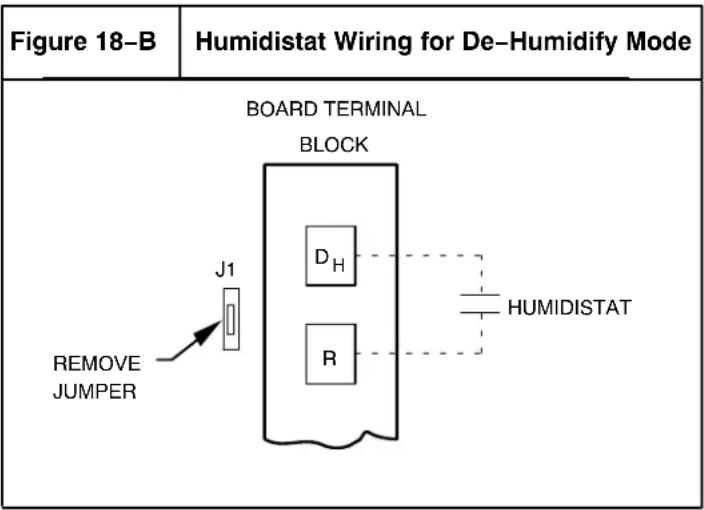
- DEHUMIDIFICATION - Remove J1 jumper to activate dehumidification mode, and install humidistat control (see Humidistat Wiring for De-Humidify mode Figure 18-B).
ACCESSORIES
A. ACCESSORY ELECTRIC HEATERS
Electric heaters may be installed with the FVM fan coil per instructions supplied with electric heater package. See unit rating plate for factory-approved electric heater kits.
B. AUXILIARY TERMINALS
The AUX2 and HUM2 terminals on the Fan Control Board are tied directly to the G terminal, and provide a 24 VAC signal whenever the G terminal is energized. (Refer to Figure 17 and Figure 18)
C. HUMIDIFIER / HUMIDISTAT CONNECTIONS
Fan Control Board terminals HUM1 (directly connected internally to C on terminal block) and HUM2 (directly connected internally to G on terminal block) are provided for direct connections to the low-voltage control of a humidifier through a standard humidistat (refer to Figure 19). These terminals are energized with 24 VAC when G thermostat signal is present (refer to Figure 22). Alternately, the 24VAC signal may be sourced from the W1 and C terminal block connections when electric heaters are used as a primary heating source (refer to Figure 20). When using a thermostat with humidity control, the 24VAC signal may be sourced directly from humidity terminal on the thermostat. (Refer to Figure 9, Figure 10, Figure 11, or Figure 12.)

| Figure 20 | Humidifier Wiring for Electric Heat Primary Heating Source |
| (TERMINAL BOARD HUMIDISTAT CONNECTIONS) C 24-VAC W TO HUMIDIFIER | |
D. DEHUMIDIFY CAPABILITY WITH STANDARD HUMIDISTAT CONNECTION, NOTE: FVM4X ** B * DEHUMIDIFICATION FUNCTIONALITY HAS CHANGED FROM PREVIOUS FAN COIL SERIES
Latent capacities for systems using the FVM fan coil are better than average systems. If increased latent capacity is an application requirement, the field wiring terminal block provides a connection terminal (DH) for use of a standard humidity sensor/control. The FVM will detect the humidity sensor/control contact opening on increasing humidity and reduce its airflow to approximately 80% of nominal cooling mode airflow. This reduction will increase the system latent capacity until the humidity falls to a level which causes the humidity sensor/control to close its contacts.
When the contacts close, the airflow will return to 100% of the selected cooling airflow. (See Humidist Wiring for De–Humidify Mode in the above Illustration)
FVM fan coils will supply airflow in a range which is more than twice the range of a standard fan coil. Each fan coil size is designed to provide nominal cooling capacities at 50\ °F\ °C evaporator temperature and the required airflow in order to match with any of four (4) different air conditioner or heat pump outdoor unit sizes. Table 1 outline the CFM range for the different FVM fan coils.
The blower motor is a true variable speed motor designed to deliver constant CFM. Constant CFM is valid for systems with total external static pressure between 0.1 and 0.7 inches water column.
A. CONTINUOUS FAN
•Thermostat closes circuit R to G.
- Blower runs at continuous fan airflow.
B. COOLING MODE - SINGLE STAGE
- If indoor temperature is above temperature set point and humidity is below humidity set point, thermostat closes circuits R to G, R to Y/Y2 and R to O.
NOTE: For single stage systems, do not use the Y1 terminal.
•Fan coil delivers single stage cooling airflow.
C. COOLING MODE - TWO STAGE
- First stage (low) cooling: Thermostat closes circuits to R to G, R to O, and R to Y1.
•Fan coil delivers low stage cooling airflow. - Second stage (high) cooling: Thermostat closes circuits to R to G, R to O, R to Y1 and R to Y/Y2.
- Fan coil delivers high stage cooling airflow.
D. COOLING MODE - DEHUMIDIFICATION
- If indoor temperature is above temperature set point and humidity is above humidity set point, thermostat closes circuits R to G, R to Y/Y2 and R to O and humidistat opens R to DH.
- The fan coil delivers airflow which is approximately 80% of the nominal cooling airflow to increase the latent capacity of the system.
E. ELECTRIC HEAT HEATING MODE
•Thermostat closes circuit R to W/W1, or W2
•Fan coil delivers the selected electric heat airflow.
•Thermostat closes circuits R to G and R to Y/Y2.
NOTE: For single stage systems, do not use the Y1 terminal.
- Fan coil delivers single stage heat pump heating airflow.
G. HEAT PUMP HEATING MODE - TWO STAGE
- First stage (low) heating: Thermostat closes circuits R to G and R to Y1.
•Fan coil delivers low stage heating airflow. - Second stage (high) heating: Thermostat closes R to G, R to Y1 and R to Y/Y2.
•Fan coil delivers high stage heating airflow.
H. HEAT PUMP HEATING WITH AUXILIARY ELECTRIC HEAT
•Thermostat closes circuits R to G, R to Y/Y2 and/or R to Y1 with R to W/W1 or W2 (and R to O in the case of defrost).
If the thermostat calls for electric heat when the heat pump is operating in heating or defrost, the motor will modify the airflow if necessary. The motor will provide an airflow which is safe for the operation of the electric heat. That airflow is the greater of the heat pump heating airflow and the electric heat only airflow.

CAUTION
ELECTRICAL SHOCK or UNIT DAMAGE HAZARD
Failure to carefully read and follow this CAUTION warning could result in equipment malfunction, property damage, personal injury and/or death.
Disconnect power to unit before removing or replacing connectors or servicing motor. Wait at least five (5) minutes after disconnecting power before opening motor.
Figure 21 Wiring

FAN COIL AIRFLOW
| Table 1 CFM Range | ||
| Fan Coil Size | Use with Outdoor Unit Size CFM Range | |
| 2400 | 18, 24, 30, 36 | 350 – 1200 |
| 3600 | 24, 30, 36, 42 | 415 – 1400 |
| 4800 | 30, 36, 42, 48 | 425 – 1600 |
| 6000 | 36, 42, 48, 60 | 540 – 2000 |
| Table 2 | Fan Coil Airflow Delivery (CFM) in Cooling Mode (A/C or HP) | |||||||||
| Fan Coil Size | Outdoor Unit Size | Single Stage Cooling | Two-Stage Cooling | Fan Only | ||||||
| High Low | ||||||||||
| Nominal | Dehum Nominal | High Low | High Low | Nominal | Dehum Low Med | Hi | ||||
| 2400 | 18 | 525 | 420 | Two-Stage outdoor unit not offered | 350 | 420 | 525 | |||
| 24 | 700 | 560 | 700 | 560 | 560 | 450 | 350 | 560 | 700 | |
| 30 | 875 | 700 | Two-Stage outdoor unit not offered | 440 | 700 | 875 | ||||
| 36 | 1050 | 840 | 1050 | 840 | 840 | 670 | 525 | 840 | 1050 | |
| 3600 | 24 | 700 | 560 | 700 | 560 | 560 | 450 | 415 | 560 | 700 |
| 30 | 875 | 700 | Two-Stage outdoor unit not offered | 440 | 700 | 875 | ||||
| 36 | 1050 | 840 | 1050 | 840 | 840 | 670 | 525 | 840 | 1050 | |
| 42 | 1225 | 980 | Two-Stage outdoor unit not offered | 615 | 980 | 1225 | ||||
| 4800 | 30 | 875 | 700 | Two-Stage outdoor unit not offered | 440 | 700 | 875 | |||
| 36 | 1050 | 840 | 1050 | 840 | 840 | 670 | 525 | 840 | 1050 | |
| 42 | 1225 | 980 | Two-Stage outdoor units not offered | 615 | 980 | 1225 | ||||
| 48 | 1400 | 1120 | 1400 | 1120 | 1120 | 900 | 700 | 1120 | 1400 | |
| 6000 | 36 | 1050 | 840 | 1050 | 840 | 840 | 670 | 540 | 840 | 1050 |
| 42 | 1225 | 980 | Two-Stage outdoor unit not offered | 615 | 980 | 1225 | ||||
| 48 | 1400 | 1120 | 1400 | 1120 | 1120 | 900 | 700 | 1120 | 1400 | |
| 60 | 1750 | 1400 | 1750 | 1400 | 1400 | 1120 | 875 | 1400 | 1750 | |
NOTES:
-
The above airflows result with the AC/HP CFM ADJUST select jumper set on NOM.
-
Airflow can be adjusted +15% or -10% by selecting Hi or Lo respectively for all modes except fan only.
-
Dry coil at 230 volts and with 10kW heater and filter installed.
-
Airflows shown are valid for systems with total static pressure between 0.1 and 0.7 in. w. c.
| Table 3 Fan Coil Airflow Delivery (CFM) in Heat Pump Heating Mode Only | ||||||||||
| Fan Coil Size | Outdoor Unit Size | Single Stage HP Heating | Two-Stage HP Heating | Fan Only | ||||||
| High Low | ||||||||||
| Comfort | Eff Comfort | Eff Comfort | Eff Low | Low Med Hi | ||||||
| 2400 | 18 475 | 525 | Two-Stage outdoor | door unit not offered 350 380 475 | ||||||
| 24 630 | 700 | 630 | 700 505 560 | 350 505 | 630 | |||||
| 30 | 785 | 875 | Two-Stage outdoor unit not offered | 440 | 630 | 785 | ||||
| 36 | 945 | 1050 | 945 | 1050 | 755 | 840 | 525 | 755 | 945 | |
| 3600 | 24 630 | 700 | 630 | 700 505 560 | 415 | 505 630 | ||||
| 30 | 785 | 875 | Two-Stage outdoor unit not offered | 440 | 630 | 785 | ||||
| 36 | 945 | 1050 | 945 | 1050 | 755 | 840 | 525 | 755 | 945 | |
| 42 | 1100 | 1225 | Two-Stage outdoor unit not offered | 615 | 880 | 1100 | ||||
| 4800 | 30 | 785 | 875 | Two-Stage outdoor unit not offered | 440 | 630 | 785 | |||
| 36 | 945 | 1050 | 945 | 1050 | 755 | 840 | 525 | 755 | 945 | |
| 42 | 1100 | 1225 | Two-Stage outdoor units not offered | 615 | 880 | 1100 | ||||
| 48 | 1260 | 1400 | 1260 | 1400 | 1010 | 1120 | 700 | 1010 | 1260 | |
| 6000 | 36 | 945 | 1050 | 945 | 1050 | 755 | 840 | 540 | 755 | 945 |
| 42 | 1100 | 1225 | Two-Stage outdoor unit not offered | 615 | 880 | 1100 | ||||
| 48 | 1260 | 1400 | 1260 | 1400 | 1010 | 1120 | 700 | 1010 | 1260 | |
| 60 | 1575 | 1750 | 1575 | 1750 | 1260 | 1400 | 875 | 1260 | 1575 | |
NOTES:
1. The above airflows result with the AC/HP CFM ADJUST select jumper set on NOM.
2. Airflow can be adjusted +15% or -10% by selecting Hi or Lo respectively for all modes except fan only.
3. Dry coil at 230 volts and with 10kW heater and filter installed.
4. Airflows shown are valid for systems with total static pressure between 0.1 and 0.7 in. w. c.
| Table 4 | Airflow Delivery (CFM) | ||||||||||||
| FVM Model Size | Outdoor Unit Capacity (BTUH) | Electric Heater kW Range | |||||||||||
| 0 - 5 | 0 - 10 | 0 - 15 | 0 - 20 | ||||||||||
| LO | NOM | HI | LO | NOM | HI | LO | NOM | HI | LO | NOM | HI | ||
| 2400 | 18 | 625 | 625 | 625 | 675 | 675 | 675 | * | * | * | * | * | * |
| 24 | 650 | 725 | 835 | * | 725 | 835 | 875 | 875 | 875 | * | * | * | |
| 30 | 815 | 905 | 1040 | * | 905 | 1040 | 900 | 900 | 1040 | 1100 | 1100 | 1100 | |
| 36 | 980 | 1085 | 1250 | 980 | 1085 | 1250 | 980 | 1085 | 1250 | 1100 | 1100 | 1250 | |
| 3600 | 24 | 675 | 725 | 835 | 875 | 875 | * | * | * | * | * | * | * |
| 30 | 815 | 905 | 1040 | 875 | 905 | 1040 | 1100 | 1100 | 1100 | * | * | * | |
| 36 | 980 | 1085 | 1250 | 980 | 1085 | 1250 | 1100 | 1100 | 1250 | 1225 | 1225 | 1250 | |
| 42 | 1140 | 1270 | 1460 | 1140 | 1270 | 1460 | 1140 | 1270 | 1460 | 1225 | 1270 | 1460 | |
| 0 - 10 | 0 - 15 | 0 - 20 | 0 - 30 | ||||||||||
| 4800 | 30 | 975 | 975 | 1040 | 1100 | 1100 | 1100 | * | * | * | * | * | * |
| 36 | 980 | 1085 | 1250 | 1100 | 1100 | 1250 | 1250 | 1250 | 1250 | * | * | * | |
| 42 | 1140 | 1270 | 1460 | 1140 | 1270 | 1460 | 1250 | 1270 | 1460 | * | * | * | |
| 48 | 1305 | 1450 | 1665 | 1305 | 1450 | 1665 | 1305 | 1450 | 1665 | 1500 | 1500 | 1665 | |
| 6000 | 36 | 1100 | 1100 | 1250 | 1350 | 1350 | 1350 | * | * | * | * | * | * |
| 42 | 1140 | 1270 | 1460 | 1350 | 1350 | 1460 | 1525 | 1525 | 1525 | * | * | * | |
| 48 | 1305 | 1450 | 1665 | 1350 | 1450 | 1665 | 1525 | 1525 | 1665 | 1750 | 1750 | 1750 | |
| 60 | 1630 | 1810 | 2085 | 1630 | 1810 | 2085 | 1630 | 1810 | 2085 | 1750 | 1810 | 2085 | |
* Airflow not recommended for heater/system size
NOTE: LO, NOM, and HI refer to AC/HP CFM ADJUST selection on the control board.
| Table 5 Heat Pump Minimum CFM for Electric Heater Application | ||||||
| FVM Model Size | Outdoor Unit Size | Heater Size kW | ||||
| 5 8, 9, 10 | 15 18, 20 24, | 30 | ||||
| 2400 | 18 625 625 -- | -- | -- | |||
| 24 650 725 875 -- | -- | -- | ||||
| 30 800 875 875 1040 -- | ||||||
| 36 970 970 970 1040 -- | ||||||
| 3600 | 24 675 875 -- | -- | -- | |||
| 30 800 875 1100 1150 -- | ||||||
| 36 975 975 1100 1225 -- | ||||||
| 42 1125 1125 1125 1225 -- | ||||||
| 4800 | 30 800 875 875 1150 -- | |||||
| 36 975 975 1100 1225 -- | ||||||
| 42 1125 1125 1125 1225 -- | ||||||
| 48 1305 1305 1305 1305 1400 | ||||||
| 6000 | 36 1100 1100 1350 1350 -- | |||||
| 42 1125 1125 1350 1350 -- | ||||||
| 48 1300 1300 1350 1465 1750 | ||||||
| 60 1625 1625 1625 1750 1750 | ||||||
| A/C Minimum CFM when using Electric Heat (CFM) | ||||||
| FVM Model Size | Heater Size kW | |||||
| 5 8, 9, 10 | 15 18, 20 24, | 30 | ||||
| 2400 | Heater Only | 625 625 | 725 875 -- | |||
| 3600 | 675 700 | 850 1050 -- | ||||
| 4800 | 675 700 | 850 1050 1400 | ||||
| 6000 | 1050 1050 | 1050 1050 1750 | ||||
NOTES:
- Heater Only-Air conditioner with electric heater application.
- These airflows are minimum acceptable airflows as UL listed. Actual airflow delivered will be per airflow delivery chart for Electric Heating Modes.
ECM MOTOR AND CONTROL
The ECM motor used with this product contains two parts: The control module and motor winding section. Do not assume the motor or module is defective if it will not start. Go through the steps described below before replacing control module, Fan Control Board or entire motor. The control module is available as a replacement part.
TROUBLESHOOTING ECM MOTOR AND CONTROLS
A. IF MOTOR TURNS SLOWLY:
- Replace access panel. Motor may appear to run slowly if access panel is removed.
- It is normal operation to run noticeable slower if G terminal is not energized in cooling or heat-pump modes.
B. IF MOTOR DOES NOT RUN:
Turn off power and check the following:
- Check 5 amp fuse on Fan Control Board.
- Check for 24 VAC on SEC1 and SEC2. If no voltage is present, check transformer.
-
Check all plugs and receptacles for any deformation which could cause loose connections. Be sure plugs are fully seated.
-
Verify that approximately 230 VAC is present at motor.
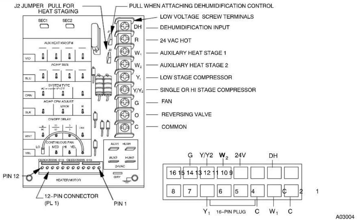
- Verify low-voltage control signals to motor. The motor receives its control signals through the 12-pin plug (PL-1) on Fan Control Board and 16-pin plug on wiring harness. (Refer to Troubleshooting Example.) The combinations of pins energized will determine motor speed. (Refer to Figure 22). Refer to Table 6 for circuit board, low-voltage screw terminals energized and for voltage present at each pin on 12-pin plug (PL-1). Refer to Table 6 for pin number on 16-pin plug which should have voltage when Fan Control Board screw terminals have 24 VAC.
Figure 22 CONTROL SIGNALS (FAN CONTROL BOARD & 16-Pin PLUG)
C. USE THE FOLLOWING PROCEDURE TO CHECK CONTROL SIGNALS:
THERMOSTAT
- Remove all thermostat wires from Fan Control Board.
- Jumper screw terminals (one at a time): R-G, R-Y/Y2, R-Y1, R-W1. If motor runs in all cases, thermostat is miswired, configured incorrectly or defective. If motor runs in some cases, but not others, continue to check wiring harness and circuit board.
WIRING HARNESS
-
Shut off power to unit; wait five (5) minutes.
-
Remove 5-pin plug from motor.
-
Remove 16-pin from motor.
-
Replace 5-pin plug and turn power on.
-
Check for appropriate voltages on 16-pin connector with screw terminals jumpered. (Refer to Table 6 for values and refer to examples below.)
If signals check correctly and motor does not run, inspect wiring harness for loose pins or damaged plastic that could cause poor connections. If connections are good, either control module or motor is defective. If proper signals are not present, check circuit board using procedure below:
12-PIN PLUG (PL-1) ON FAN CONTROL BOARD
- Unplug harness from board.
- Check for appropriate voltages on pins with Fan Control Board screw terminals jumpered. (Refer to Table 6 for values and refer to example below.)
If proper signals are not present, replace Fan Control Board. If present at board and not at 16-pin connector, wiring harness is defective.
TROUBLESHOOTING EXAMPLE:
Motor is not running on a call for heat pump heating. System is a single-stage heat pump.
-
After performing checks in Thermostat section, follow Steps 1 through 5 in Wiring Harness section. Then proceed with example.
-
With all thermostat wires removed from Fan Control Board, place a jumper wire between R and Y/Y2 low-voltage screw terminals on the Fan Control Board.
-
Check Table 6 for pin number on 16-pin connector associated with the Y/Y2 signal. The correct pin is #14. The far right column shows that (-) 12 VDC should be present between pin #14 and pin #1 (common) on the 16-pin connector.
-
Set meter to read DC voltage. Place meter between pins #1 and #14 and check for (-) 12 VDC (common side of meter on pin #1). If signal is present, the problem is in the module or motor. If signal is not, problem is either in wiring harness or Fan Control Board.
These steps can be repeated for other modes of operation.
| Table 6 Wiring Connections of FVM Fan Coil Wiring Harness | |||||
| 16-IN PLUG ON WIRING HARNESS TO MOTOR | WIRING HARNESS CONNECTION TO FAN CONTROL BOARD | ||||
| Pin on 16-Pin Plug | Description | Pin on 12-pin plug or Set-up Selection | Wire Color | Signal on Pin with Screw Terminal Jumpered to R* | |
| 1 Common Pin 9 on PL-1 Brown | |||||
| 2 | W1 | Aux Heat Stage 1 | Pin 7 on PL-1 | Violet | 24VAC** |
| 3 Common Pin 10 on PL-1 Orange | |||||
| 4 | On/Off Delay Selection | On/Off Delay Selection | White | ||
| 5 | AC/HP Size Selection | AC/HP Size Selection | Blue | ||
| 6 | Y1 | Low Speed AC or HP | Pin 3 on PL-1 | Black | (-) 12VDC** |
| 7 | AC/HP CFM Adjust Selection | AC/HP CFM Adjust Selection | Black | ||
| 8 | Not Used | N/A | Not Used | ||
| 9 | System Type Selection | System Type Selection | Orange | ||
| 10 | Dehumidify | Pin 12 on PL-1 | Gray | 0V (24VAC on no call) | |
| 11 | Aux Heat Size Selection | Aux Heat Size Selection | Violet | ||
| 12 | 24V AC | Pin 8 on PL-1 | Red | 24VAC continuous | |
| 13 | W2 | Aux Heat Stage 2 | Pin 4 on PL-1 | White | 24VAC** |
| 14 | Y/Y2 | Single Stage AC or HP, High Speed Two-Stage AC or HP | Pin 2 on PL-1 | Yellow | (-) 12DC** |
| 15 | G | Fan | Pin 1 on PL-1 | Green | 24VAC** |
| 16 | Not Used | N/A | Not Used | ||
* Check voltages with 16-Pin Plug disconnected from motor.
** These signals will start motor.
To check Fan Control Board:
-
Leave jumper wire in place between R and Y/Y2.
-
Check Table 6 under "Wiring Harness Connection to Fan Control Board" column and row for pin #14 to see pin# on Fan Control Board that should have voltage. The correct pin is #2. The column on far right will show voltage that should be present between pin #2 and #9 (or #10 common).
-
Place meter between pins #2 and #9 and Fan Control Board and check for (-) 12 VDC
-
If voltage is present, the wiring harness is bad; if not, the Fan Control Board is bad.
D. VERIFY MOTOR WINDING SECTION
Before proceeding with module replacement, check the following to ensure motor winding section is functional. With control module removed and unplugged from winding section:
- The resistance between any 2 motor leads should be similar.
- The resistance between any motor lead and the unpainted motor end plate should be greater than 100K ohms.
If motor winding section fails one of these tests, it is defective and must be replaced.
START-UP PROCEDURE
Refer to outdoor unit Installation Instructions for system start-up instructions and refrigerant charging method details.
CARE AND MAINTENANCE
For continuing high performance, and to minimize possible equipment failure, it is essential that periodic maintenance be performed on this equipment.
The system should be regularly inspected by a qualified service technician. Consult the servicing dealer for recommended frequency.
Between visits, the only consumer service recommended or required is air filter maintenance and condensate drain operation.
Air Filter
The only required maintenance that may be performed by the consumer if filter maintenance.
Inspect air filters at least monthly and replace or clean as required. Disposable type filters should be replaced. Reusable type filters may be cleaned by soaking in mild detergent and rinsing with cold water. Install filters with the arrows on the side pointing in the direction of air flow.
Condensate Drain
During the cooling season check at least monthly for free flow of drainage and clean if necessary.
An inspection port is provided on all A-coil delta plates. Remove plastic plug to inspect.

CAUTION
PRODUCT DAMAGE HAZARD
Failure to follow this caution may result in poor unit performance and/or product damage.
Never operate unit without a filter. Factory authorized filter kits must be used when locating the filter inside the unit. For those applications where access to an internal filter is impractical, a field-supplied filter must be installed in the return duct system.
R-410A QUICK REFERENCE GUIDE
- R-410A refrigerant operates at 50% – 70% higher pressures than R-22. Be sure that servicing equipment and replacement components are designed to operate with R-410A.
- R-410A refrigerant cylinders are rose colored.
- Recovery cylinder service pressure rating must be 400 psig, DOT 4BA400 or DOT BW400.
- R-410A systems should be charged with liquid refrigerant. Use a commercial type metering device in the manifold hose.
- Manifold sets should be 750 psig high-side and 200 psig low-side with 520 psig low-side retard.
- Use hoses with 750 psig service pressure rating.
- Leak detectors should be designed to detect HFC refrigerant.
- R-410A, as with other HFC refrigerants, is only compatible with POE oils.
- POE oils absorb moisture rapidly. Do not expose oil to atmosphere.
- POE oils may cause damage to certain plastics and roofing materials.
• Vacuum pumps will not remove moisture from oil. - A liquid line filter-drier is required on every unit.
- Do not use liquid line filter-driers with rated working pressures less than 600 psig.
- Do not install a suction line filter-drier in liquid line.
- Wrap all filter-driers and service valves with wet cloth when brazing.
- Do not use with an R-22 TXV.
- If indoor unit is equipped with an R-22 TXV, it must be changed to an R-410A TXV.
- Do not use capillary tube indoor coils.
- Never open system to atmosphere while it is under a vacuum.
- When system must be opened for service, break vacuum with dry nitrogen and replace all filter-driers.
- Do not vent R-410A into the atmosphere.
- Observe all WARNINGS, CAUTIONS, NOTES, and bold text.
TRAINING
My Learning Center is your central location for professional residential HVAC training resources that help strengthen careers and businesses. We believe in providing high quality learning experiences both online and in the classroom.
Please contact us at mylearning@icpusa.com with questions regarding access to My Learning Center.
Copyright 2019 International Comfort Products
Lewisburg, TN 37091 USA
- INSTALLATION INSTRUCTIONS
- FAN COILS
- FVM4X "B" SERIES
- SAFETY LABELING AND SIGNAL WORDS
- DANGER, WARNING, CAUTION, AND NOTE
- SIGNAL WORDS IN MANUALS
- WARNING
- CAUTION
- SIGNAL WORDS ON PRODUCT LABELING
- TABLE OF CONTENTS
- DEATH, PERSONAL INJURY, AND/OR PROPERTY DAMAGE HAZARD
- INTRODUCTION
- LOCATION
- HEATER PACKAGES
- POSITION UNIT
- PROPERTY DAMAGE HAZARD
- FIRE HAZARD
- UPFLOW INSTALLATION
- MODULAR UNITS
- HORIZONTAL INSTALLATION
- HORIZONTAL RIGHT CONVERSION OF UNITS WITH SLOPE COILS
- HORIZONTAL RIGHT CONVERSION OF UNITS WITH A-COILS
- DOWNFLOW INSTALLATION
- PRODUCT OR PROPERTY DAMAGE HAZARD
- MANUFACTURED HOUSING AND MOBILE HOME APPLICATIONS
- AIR DUCTS
- DUCT WORK ACOUSTICAL TREATMENT
- ELECTRICAL CONNECTIONS
- ELECTRICAL SHOCK OR UNIT DAMAGE HAZARD
- LINE VOLTAGE CONNECTIONS
- 24V CONTROL SYSTEM
- CONTROL SYSTEM CONNECTIONS TO FAN CONTROL BOARD
- HEAT STAGING
- HEAT STAGING OPTION
- MANUFACTURED HOUSING
- TRANSFORMER INFORMATION
- REFRIGERANT TUBING
- PRODUCT DAMAGE HAZARD
- REFRIGERANT METERING DEVICE
- GROUND CONNECTIONS
- ELECTRICAL SHOCK HAZARD
- CONDENSATE DRAINS
- BLOWER MOTOR - CFM
- FAN CONTROL BOARD CONFIGURATION TAPS
- AUXILIARY HEAT KW/CFM
- AC/HP SIZE
- SELECT SYSTEM SIZE INSTALLED
- SYSTEM TYPE
- SELECT SYSTEM TYPE INSTALLED AC OR HP
- AC/HP CFM ADJUST
- SELECT MEDIUM, LOW, OR HIGH AIRFLOW
- ON/OFF DELAY
- SELECT DESIRED TIME DELAY PROFILE
- CONTINUOUS FAN
- SELECT DESIRED FAN SPEED WHEN THERMOSTAT IS SET ON CONTINUOUS FAN
- LOW-VOLTAGE CIRCUIT
- FUSING AND REFERENCE
- BASIC FAN COIL CONFIGURATION
- ACCESSORIES
- ACCESSORY ELECTRIC HEATERS
- AUXILIARY TERMINALS
- HUMIDIFIER / HUMIDISTAT CONNECTIONS
- DEHUMIDIFY CAPABILITY WITH STANDARD HUMIDISTAT CONNECTION, NOTE: FVM4X ** B * DEHUMIDIFICATION FUNCTIONALITY HAS CHANGED FROM PREVIOUS FAN COIL SERIES
- COOLING MODE - SINGLE STAGE
- COOLING MODE - TWO STAGE
- COOLING MODE - DEHUMIDIFICATION
- ELECTRIC HEAT HEATING MODE
- HEAT PUMP HEATING MODE - TWO STAGE
- HEAT PUMP HEATING WITH AUXILIARY ELECTRIC HEAT
- NOTES
- ECM MOTOR AND CONTROL
- TROUBLESHOOTING ECM MOTOR AND CONTROLS
- IF MOTOR TURNS SLOWLY
- IF MOTOR DOES NOT RUN
- USE THE FOLLOWING PROCEDURE TO CHECK CONTROL SIGNALS
- THERMOSTAT
- WIRING HARNESS
- 12-PIN PLUG (PL-1) ON FAN CONTROL BOARD
- TROUBLESHOOTING EXAMPLE
- VERIFY MOTOR WINDING SECTION
- START-UP PROCEDURE
- CARE AND MAINTENANCE
- AIR FILTER
- CONDENSATE DRAIN
- R-410A QUICK REFERENCE GUIDE
- TRAINING
Brand : Arcoaire
Model : FVM4X6000BL
Category : Home Fan