
NA1PK5PN - Sensors PANASONIC - Free user manual and instructions
Find the device manual for free NA1PK5PN PANASONIC in PDF.


| Product Type | Photoelectric Sensor |
| Model | NA1PK5PN |
| Brand | Panasonic |
| Dimensions (HxWxD) | 34 x 20 x 12 mm |
| Weight | Approx. 50 g |
| Power Supply | 12-24 V DC ±10% |
| Current Consumption | ≤ 30 mA |
| Sensing Method | Through-beam type |
| Sensing Distance | Up to 5 m |
| Response Time | ≤ 1 ms |
| Output Type | NPN open collector |
| Protection Circuit | Reverse polarity, surge protection |
| Ambient Temperature | -25°C to +55°C |
| Protection Rating | IP67 |
| Material (Housing) | Polycarbonate |
| Light Source | Red LED (visible) |
| Emitter/Receiver | Separate unit |
| Connection | Pre-wired cable (2 m) |
| Main Functions | Object detection, indicator LED |
| Cleaning and Maintenance | Clean lens with soft cloth; avoid solvents |
| Safety Precautions | Do not exceed rated voltage; avoid direct eye exposure to beam |
| Spare Parts / Repairability | Contact Panasonic service center; not user-serviceable |
| General Information | CE marked; RoHS compliant |
Frequently Asked Questions - NA1PK5PN PANASONIC
User questions about NA1PK5PN PANASONIC
0 question about this device. Answer the ones you know or ask your own.
Ask a new question about this device
Download the instructions for your Sensors in PDF format for free! Find your manual NA1PK5PN - PANASONIC and take your electronic device back in hand. On this page are published all the documents necessary for the use of your device. NA1PK5PN by PANASONIC.
USER MANUAL NA1PK5PN PANASONIC
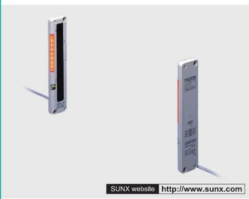
Ultra-slim Body Picking Sensor
NA1-PK5 SERIES NA1-5 SERIES
Related Information
■ General terms and conditions..... P.1
■ Glossary of terms....P.983\~
■ Sensor selection guide .....P.11\~ / P.443\~
■ General precautions ...... P.986\~
natural_image
Two industrial sensor modules with visible wiring, one with orange indicator lights and the other with red label (no text or symbols on the modules themselves)


Make sure to use light curtains when using a sensing device for personnel protection. Refer to p.447\~ for the light curtains.

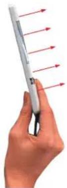
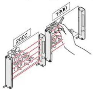
Even a slim hand is detected by the 25 mm 0.984 in pitch beam curtain
10 mm 0.394 in thick: half the thickness of conventional models
Space savings now possible; ultra-thin design does not obstruct picking operations.
natural_image
Hand holding a pen with red arrows pointing outward, no visible text or symbols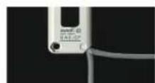
Cable can be freely arranged in any position
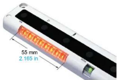
Clearly visible job indicator
Bright, easy-to-see job indicators, 55 mm 2.165 in length, have been incorporated into both the emitter and the receiver.
This sensor is optimal for picking. With the NA1-PK5, we've enhanced visibility even further by using 8 orange LED lights.
BASIC PERFORMANCE
Long sensing range: 3 m 9.843 ft
NA1-5
Its long sensing range of 3 m 9.843 ft is sufficient for confi rming access to a parts shelf.
FUNCTIONS
Two unit installations are possible
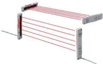
Sensor units can now be set to different light emission frequencies, in order to prevent mutual interference. Two units can now be operated in a side-by-side configuration without interference, for problem-free detection over wider areas.
natural_image
3D diagram of a mechanical or electrical component with red lines extending outward, no visible text or symbolsAPPLICATIONS
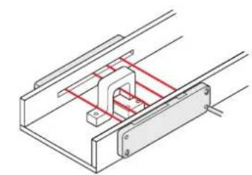
Preventing wrong parts picking Detecting parts having wide positioning area
natural_image
Technical line drawing of a mechanical assembly with red and gray components (no text or symbols)
WARNING
Never use this product in any personnel safety application.
FUNCTIONS
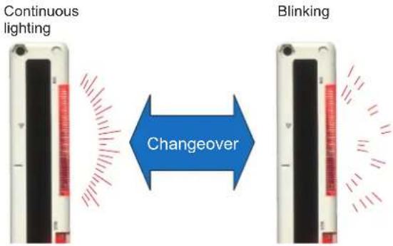
Lighting pattern selectable
The job indicator operation can be selected as either continuous lighting or blinking.
Selectable detection operation
Either of two different detection operations may be selected, in order to best suit the particular application. Sensor units can be set to detect the interruption of 1 or more beam channels, or can be set to detect only the interruption of 2 or more beam channels.
Single beam interruption Double beam interruption
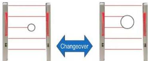
All opaque bodies with 35 mm 1.378 in or greater will be detected.
The accidental passage of small objects through the beam axis will not trigger detection, yet the operator's hands will always be accurately detected. This function is also useful when small objects regularly interrupt the beam axis.
ORDER GUIDE
| Type Appearance | Sensing range (Note) | Model No. Output | ||
| High-luminous job indicator type | 0.1 to 1.2 m0.328 to 3.937 ft(0.05 to 0.5 m 0.164 to 1.640 ft) when set to SHORT. | NA1-PK5 | NPN open-collector transistor | |
| NA1-PK5-PN | PNP open-collector transistor | |||
| Long sensing range type | 5 beam channels Beam pitch25 mm 0.984 in | 0.2 to 3 m0.656 to 9.843 ft(0.05 to 1 m 0.164 to 3.281 ft) when set to SHORT. | NA1-5 | NPN open-collector transistor |
| NA1-5-PN | PNP open-collector transistor | |||
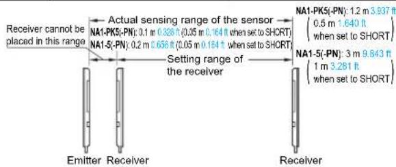
Notes: 1) The sensing range is the possible setting distance between the emitter and the receiver.
NA1-PK5(-PN) can detect an object less than 0.1 m 0.328 ft
(0.05 m 0.164 ft when set to SHORT) away. NA1-5(-PN) can detect an object less than 0.2 m 0.656 ft (0.05 m 0.164 ft when set to SHORT) away.
2) The model No. with suffix "P" shown on the label affixed to the product is the emitter, "D" shown on the label is receiver.
(e.g.) Emitter of NA1-PK5: NA1-PK5P,
Receiver of NA1-PK5: NA1-PK5D
| Receiver | Actual sensing range of the sensor | |
| NA1-PK5(-PN): 0.1 m 0.328 ft (0.35 m 0.164 ft when set to SHORT) | ||
| NA1-5(-PN): 0.2 m 0.658 ft (0.05 m 0.164 ft when set to SHORT) | ||
| Setting range of the receiver | ||
| NA1-PK5(-PN): 1.2 m 3.937 ft(0.5 m 1.640 ftwhen set to SHORT) | ||
| NA1-5(-PN): 3 m 9.843 ft(1 m 3.281 ftwhen set to SHORT) | ||
| Emitter Receiver | Receiver | |
FIBER SENSORS
LASER SENSORS
PHOTOELECTRIC SENSORS
MICRO PHOTOELECTRIC SENSORS
AREA SENSORS
SAFETY COMPONENTS
PRESSURE SENSORS
INDUCTIVE PROXIMITY SENSORS
PARTICULAR USE SENSORS
SENSOR OPTIONS
WIRE-SAVING SYSTEMS
MEASUREMENT SENSORS
STATIC CONTROL DEVICES
LASER MARKERS
Selection Guide
Slim Body
NA2-N
Picking
NA1-PK5 / NA1-5
NA1-PK3
Other Products
ORDER GUIDE
5 m 16.404 ft cable length type
5 m 16.404 ft cable length type (standard: 2 m 6.562 ft) is also available. Model No.: NA1-5-C5
Pigtailed type
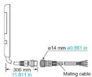
Pigtailed type is also available. When ordering this type, suffix "-J" to the model No. Please order the mating cable separately. (e.g.) Pigtailed type of NA1-PK5-PN is "NA1-PK5-PN-J".
Mating cable (2 cables are required.)•
| Model No. Description | |
| CN-24-C2 | 4-core, cable length 2 m 6.562 ft |
| CN-24-C5 | 4-core, cable length 5 m 16.404 ft |
S-LINK direct hook-up picking sensor
SL-N15 can be hooked up to the sensor & wire-saving link system S-LINK. Refer to p.807\~ for the S-LINK.
| Model No. Description | ||
| SL-N15 | Sensing range: 0.2 to 3 m 0.656 to 9.843 ft(0.05 to 1 m 0.164 to 3.281 ft)when the switch is set to SHORT)Beam pitch: 25 mm 0.984 inSensing height: 100 mm 3.937 inSensing object: ø35 mm ø1.378 in or more opaque object | It is a parts-taking verification sensor with fi ve sensing beams and can be hooked up to the S-LINK cable without any interface.Both the emitter and the receiver are incorporated with bright orange LED job indicators that are easily visible to the operator. |
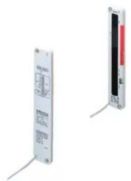
natural_image
Two electronic device modules with visible wiring and indicator lights (no text or symbols)OPTIONS
| Designation Model No. Description | ||
| Sensor mounting bracket | MS-NA1-1 | Four bracket set[ Four M4 (length 15 mm 0.591 in) screws with washers, eight nuts, four hooks, four spacers and eight M4 (length 18 mm 0.709 in) screws with washers are attached.(Spacers are not attached with MS-NA1-1.) |
| MS-NA2-1 | ||
| Sensor protection bracket | MS-NA3 | It protects the sensor body.Two silver bracket set[ Four M4 (length 15 mm 0.591 in) screws with washers, and four nuts are attached. |
| MS-NA3-BK | It protects the sensor body.Two black bracket set[ Four M4 (length 15 mm 0.591 in) screws with washers, and four nuts are attached. | |
| Slit mask | OS-NA1-510 pcs. per set | The slit mask restrains the amount of beam emitted or received (Seal type) |
| Y-shaped connector | SL-WY5 pcs. per set | This connector is able to combine the cables of receiver and emitter into one. |
Sensor mounting bracket
MS-NA1-1•

M4 screws with washers, nuts and hooks are attached.
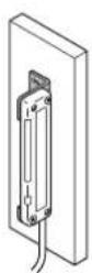
MS-NA2-1•

M4 screws with washers, nuts, and, hooks and spacers are attached.
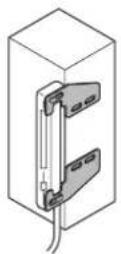
Sensor protection bracket
• MS-NA3
• MS-NA3-BK
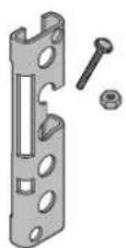
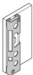
M4 screws with washers, and nuts are attached.
Slit mask
OS-NA1-5•
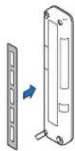
Since the slit mask is seal type, it can be used by sticking it to the detection surface.
Take care that the sensing range will be reduced when the slit mask is used. Please contact our offi ce for details.
Y-shaped connector
SL-WY•
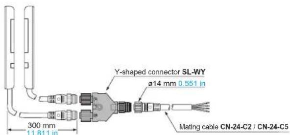
SPECIFICATIONS
| TypeItem Model No. NA1-PK5 NA1-5 NA1-PK5-PN NA1-5-PN | NPN output PNP output | ||||
| High-luminous job indicator type | Long sensing range type | High-luminous job indicator type | Long sensing range type | ||
| Sensing height 100 mm 3.937 in | |||||
| Sensing range (Note 2) | 0.1 to 1.2 m 0.328 to 3.937 ft(0.05 to 0.5 m 0.164 to 1.640 ft when set to SHORT) | 0.2 to 3 m 0.656 to 9.843 ft(0.05 to 1 m 0.164 to 3.281 ft when set to SHORT) | 0.1 to 1.2 m 0.328 to 3.937 ft(0.05 to 0.5 m 0.164 to 1.640 ft when set to SHORT) | 0.2 to 3 m 0.656 to 9.843 ft(0.05 to 1 m 0.164 to 3.281 ft where set to SHORT) | |
| Beam pitch 25 mm 0.984 in | |||||
| Number of beam channels 5 beam channels | |||||
| Sensing object ø35 mm | ø1.378 in or more opaque object (completely beam interrupted object) | ||||
| Supply voltage 12 to 24 V DC ± | 10 % Ripple P-P 10 % or less | ||||
| Power consumption (Note 3) | Emitter: 0.5 W or less, Receiver: 0.8 W or less | Emitter: 0.6 W or less, Receiver: 0.9 W or less | |||
| Output | NPN open-collector transistorMaximum sink current: 100 mAApplied voltage: 30 V DC or less (between output and 0 V)Residual voltage: 1 V or less (at 100 mA sink current)0.4 V or less (at 16 mA sink current) | PNP open-collector transistorMaximum source current: 100 mAApplied voltage: 30 V DC or less (between output and +V)Residual voltage: 1 V or less (at 100 mA source current)0.4 V or less (at 16 mA source current) | |||
| Utilization category | DC-12 or DC-13 | ||||
| Output operation | ON or OFF when one or more beam channels are interrupted /ON or OFF when two or more beam channels are interrupted,selectable by operation mode switch | ||||
| Short-circuit protection | Incorporated | ||||
| Response time | 10 ms or less (when the interference prevention is used, in Light state: 30 ms or less, in Dark state: 13 ms or less) | ||||
| indicators | Emitter | Power indicator: Green LED (lights up when the power is ON)Job indicator: Orange LED (lights up or blinks when the job indicator input is Low, lighting pattern is selected by operation mode switch) | Power indicator: Green LED (lights up when the power is ON)Job indicator: Orange LED (lights up or blinks when the job indicator input is High, lighting pattern is selected by operation mode switch) | ||
| Receiver | Operation indicator: Red LED (lights up when one or more beam channels are interrupted, but lights up when two beam channels or more are interrupted in the double-beam-interruption mode)Stable incident beam indicator: Green LED (lights up when all beam channels are stably received)Job indicator: Orange LED (lights up or blinks when the job indicator input is Low, lighting pattern is selected by operation mode switch) | Operation indicator: Red LED (lights up when one or more beam channels are interrupted, but lights up when two beam channels or more are interrupted in the double-beam-interruption mode)Stable incident beam indicator: Green LED (lights up when all beam channels are stably received)Job indicator: Orange LED (lights up or blinks when the job indicator input is High, lighting pattern is selected by operation mode switch) | |||
| Interference prevention function | Incorporated | ||||
| Environmental resistance | Pollution degree | 3 (Industrial environment) | |||
| Protection | IP62 (IEC) (Refer to p.984 for details of standards.) | ||||
| Ambient temperature | -10 to +55 °C +14 to +131 °F (No dew condensation or icing allowed), Storage: -20 to +70 °C -4 to +158 °F | ||||
| Ambient humidity | 35 to 85 % RH, Storage: 35 to 85 % RH | ||||
| Ambient illuminance | Incandescent light: 3,000 fx at the light-receiving face | ||||
| EMC | EN 60947-5-2 | ||||
| Voltage withstandability | 1,000 V AC for one min. between all supply terminals connected together and enclosure | ||||
| Insulation resistance | 20 MΩ, or more, with 250 V DC megger between all supply terminals connected together and enclosure | ||||
| Vibration resistance | 10 to 150 Hz frequency, 0.75 mm 0.030 in amplitude in X, Y and Z directions for two hours each | ||||
| Shock resistance | 490 m/s2 acceleration (50 G approx.) in X, Y and Z directions for three times each | ||||
| Emitting element | Infrared LED (Peak emission wavelength: 950 nm 0.037 ml, synchronized scanning system) | ||||
| Material | Enclosure: Heat-resistant ABS, Lens cover: Acrylic, Indicator cover: Acrylic | ||||
| Cable | 0.3 mm2 4-core (emitter: 3-core) oil resistant cablyre cable, 2 m 6.562 ft long | ||||
| Cable extension | Extension up to total 100 m 328.084 ft is possible for both emitter and receiver with 0.3 mm2, or more, cable. | ||||
| Weight | Net weight:Emitter 80 g approx.Rceiver 85 g approx.Gross weight: 270 g approx. | Net weight:Emitter 70 g approx.Rceiver 80 g approx.Gross weight: 270 g approx. | Net weight:Emitter 80 g approx.Rceiver 85 g approx.Gross weight: 270 g approx. | Net weight:Emitter 70 g approx.Receiver 80 g approx.Gross weight: 270 g approx. | |
Notes: 1) Where measurement conditions have not been specified precisely, the conditions used were an ambient temperature of +23 °C +73.4 °F.
2) The sensing range is the possible setting distance between the emitter and the receiver. NA1-PK5(-PN) can detect an object less than 0.1 m 0.328 ft (0.05 m 0.164 ft when set to SHORT) away. NA1-5(-PN) can detect an object less than 0.2 m 0.656 ft (0.05 m 0.164 ft when set to SHORT) away.
3) Obtain the current consumption by the following equation.
Current consumption = Power consumption ÷ Supply voltage (e.g.) When the supply voltage is 12 V,
the current consumption of the emitter is:
0.5 W ÷ 12 V ≈ 0.042 A = 42 mA
I/O CIRCUIT AND WIRING DIAGRAMS
NA1-PK5 NA1-5
NPN output type
I/O circuit diagram Wiring diagram
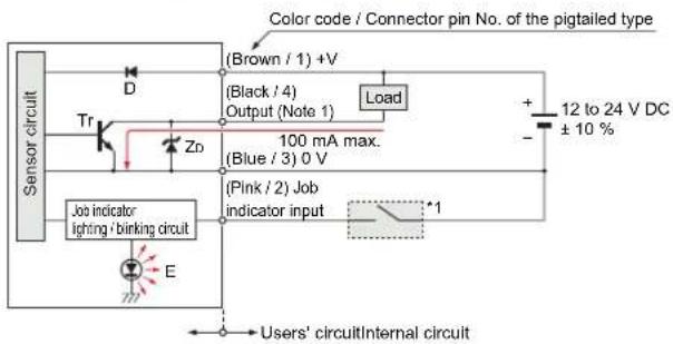
Notes: 1) The emitter does not incorporate the output (black). 2) Unused wire must be insulated to ensure that they do not come into contact with wires already in use.
Symbols ... D : Reverse supply polarity protection diode
ZD: Surge absorption zener diode
Tr : NPN output transistor
E : Job indicator (IND.)
*1
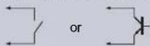
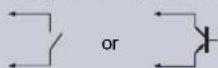
Non-contact voltage or NPN open-collector transistor
• Job indicator input
Low (0 to 2 V): Lights up or Blinks
High (5 to 30 V, or open): Lights off
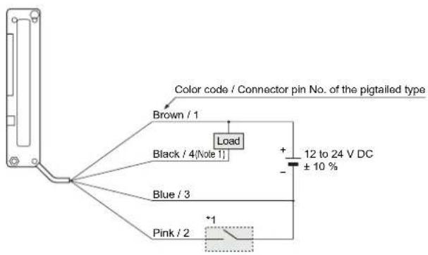
Notes: 1) The emitter does not incorporate the black lead wire.
2) Unused wires must be insulated to ensure that they do not come into contact with wires already in use.
Connector pin position (Pigtailed type)
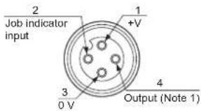
Notes: 1) No connection is required for the emitter.
2) The pin arrangement of the SL-WY Y-shaped connector (optional) is identical to the receiver.
NA1-PK5-PN NA1-5-PN
PNP output type
I/O circuit diagram Wiring diagram

Notes: 1) The emitter does not incorporate the output (black). 2) Unused wire must be insulated to ensure that they do not come into contact with wires already in use.
Symbols ... D : Reverse supply polarity protection diode
ZD: Surge absorption zener diode
Tr : PNP output transistor
E : Job indicator (IND.)
*1
Non-contact voltage or PNP open-collector transistor
• Job indicator input
High (4 V or more): Lights up or Blinks
Low (0 to 0.6 V, or open): Lights off
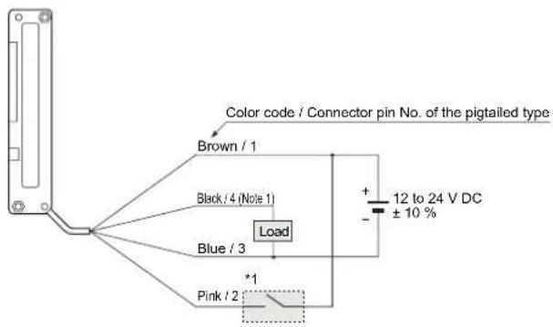
Notes: 1) The emitter does not incorporate the black lead wire.
2) Unused wires must be insulated to ensure that they do not come into contact with wires already in use.
Connector pin position (Pigtailed type)
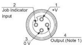
Notes: 1) No connection is required for the emitter.
2) The pin arrangement of the SL-WY Y-shaped connector (optional) is identical to the receiver.
FIBER SENSORS
LASER SENSORS
PHOTO-ELECTRIC SENSORS
MICRO PHOTO- ELECTRIC SENSORS
AREA SENSORS
SAFETY COMPONENTS
PRESSURE SENSORS
INDUCTIVE PROXIMITY SENSORS
PARTICULAR USE SENSORS
SENSOR OPTIONS
WIRE- SAVING SYSTEMS
MEASUREMENT SENSORS
STATIC CONTROL DEVICES
LASER MARKERS
Selection Guide Slim Body
NA2-N
Picking NA1-PK5 NA1-5
NA1-PK3 Other Products
SENSING CHARACTERISTICS (TYPICAL)
NA1-PK5 NA1-PK5-PN
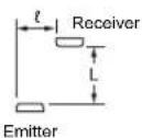
Parallel deviation
Vertical direction
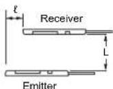
Horizontal direction
Vertical direction• Horizontal direction•
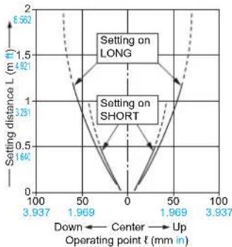
line
| Operating point t (mm in) | Setting distance L (m ft) | | ------------------------- | ------------------------- | | 100 | 2 | | 3.937 | 2 | | 50 | 1.5 | | 1.969 | 1 | | 0 | 0 | | 1.969 | 1 | | 3.937 | 2 |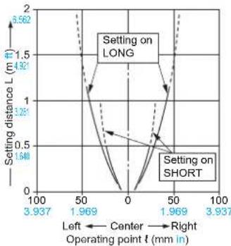
line
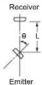
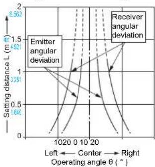
| Operating point t (mm in) | Left Center (L m ft) | Right Center (L m ft) | Left Right (L m ft) | Right Right (L m ft) | | ------------------------- | -------------------- | --------------------- | ------------------- | -------------------- | | 3.937 | 1.548 | 1.548 | 1.548 | 1.548 | | 1.969 | 0.562 | 0.562 | 0.562 | 0.562 | | 0 | 0 | 0 | 0 | 0 | | 1.969 | 0.562 | 0.562 | 0.562 | 0.562 | | 3.937 | 1.548 | 1.548 | 1.548 | 1.548 |Angular deviation
Emitter angular deviation
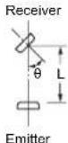
Receiver angular deviation
Setting on LONG• Setting on SHORT•
line
| Operating angle θ (°) | Setting distance L (m ft) - Emitter angular deviation | Setting distance L (m ft) - Receiver angular deviation | | --------------------- | ------------------------------------------------------ | -------------------------------------------------------- | | 0 | 1.64 | 1.56 | | 10 | 3.25 | 3.00 | | 20 | 4.82 | 4.50 |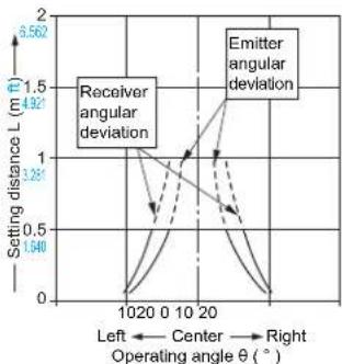
line
| Operating angle θ (°) | Setting distance L (m ft) | | --------------------- | ------------------------- | | 10 | 0 | | 20 | 1.5 | | 30 | 0 |NA1-5 NA1-5-PN
Parallel deviation
Vertical direction
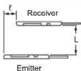
Horizontal direction
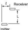
- Common for both horizontal and vertical directions
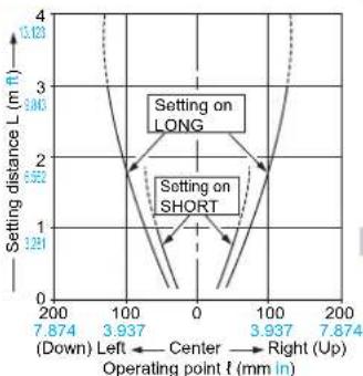
line
| Operating point f (mm in) | Setting distance L (m ft) - Setting on LONG | Setting distance L (m ft) - Setting on SHORT | |---|---|---| | 200 | 3.843 | 1.291 | | 100 | 1.291 | 0.562 | | 0 | 0.562 | 0.562 | | 100 | 1.291 | 0.562 | | 200 | 3.843 | 1.291 |Angular deviation
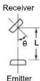
Emitter angular deviation
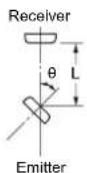
Receiver angular deviation
Setting on LONG• Setting on SHORT•
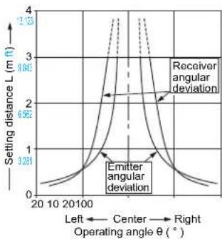
line
| Operating angle θ (°) | Setting distance L (m ft) | | --------------------- | ------------------------- | | Left | 0 | | Center | 1 | | Right | 4 |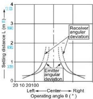
line
| Operating angle θ (°) | Receiver angular deviation | Emitter angular deviation | | --------------------- | -------------------------- | ------------------------- | | 20 | 0 | 0 | | 10 | 1 | 1 | | 0 | 2 | 2 | | 30 | 2.5 | 1.2 |PRECAUTIONS FOR PROPER USE
Refer to p.986 \~ for general precautions.

- Never use this product as a sensing device for personnel protection.
- For sensing devices to be used as safety devices for press machines or for personnel protection, use products which meet standards, such as OSHA, ANSI or IEC etc., for personnel protection applicable in each region or country.
- If this product is used as a sensing device for personnel protection, death or serious body injury could result.
- For a product which meets safety standards, use the following products.
Type4: SF4B series (p.481\~)
Type2: SF2B series (p.515\~)
Mounting
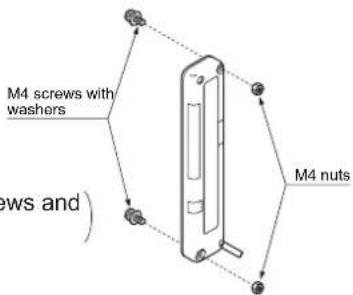
- Use M4 screws with washers and M4 nuts. The tightening torque should be 0.5 N·m or less.
(Please arrange the screws and nuts separately.
Orientation
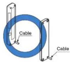
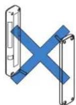
- The emitter and the receiver must face each other correctly. If they are set upside down, the sensor does not work.
Interference prevention function
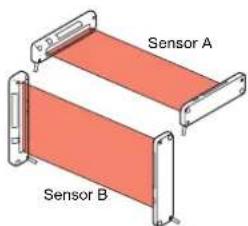
- By setting different emission frequencies, two units of the sensor can be mounted close together, as shown in the figure below.
The switches must be set with the power supply off. The operation mode does not change if the switch setting is changed with the power supplied.
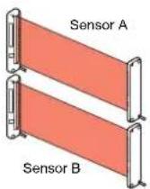
| Operation mode switch | ||
| Emitter Receiver | ||
| Sensor A(FREQ. A) | FREQ. A FREQ. B FREQ. A FREQ. B | |
| Sensor B(FREQ. B) | FREQ. A FREQ. B FREQ. A FREQ. B | |
LONG / SHORT selection switch (incorporated on the emitter)
- Select the switch setting according to the setting distance between the emitter and the receiver as given below. (The switches must be set with the power supply off. The operation mode does not change if the switch setting is changed with the power supplied.)
| Setting distance Operation mode switch | |
| 0.05 to 0.5 m 0.164 to 1.640 ft [NA1-PK5(-PN)]0.05 to 1 m 0.164 to 3.281 ft [NA1-5(-PN)] | LONG SHORT |
| 0.5 to 1.2 m 1.640 to 3.937 ft [NA1-PK5(-PN)]1 to 3 m 3.281 to 9.843 ft [NA1-5(-PN)] | LONG SHORT |
Selection of output operation
- The output operation mode is selected by the operation mode switch on the receiver.
The switches must be set with the power supply off. The operation mode does not change if the switch setting is changed with the power supplied.
| Output operation Operation | mode switch |
| ON when one or more beam channels are interrupted(OFF when all beam channels are received). | |
| OFF when one or more beam channels are interrupted(ON when all beam channels are received). | |
| ON when any two or more beam channels are interrupted. | |
| OFF when any two or more beam channels are interrupted. |
Job indicator operation selection
- Lighting / Blinking is selected by the operation mode switch on the emitter and the receiver.
(The switches must be set with the power supply off. The operation mode does not change if the switch setting is changed with the power supplied.)
| Operation mode switch | ||
| Emitter Receiver | ||
| Lighting | ||
| Blinking | ||
Others
- Do not use during the initial transient time (0.5 sec.) after the power supply is switched on.
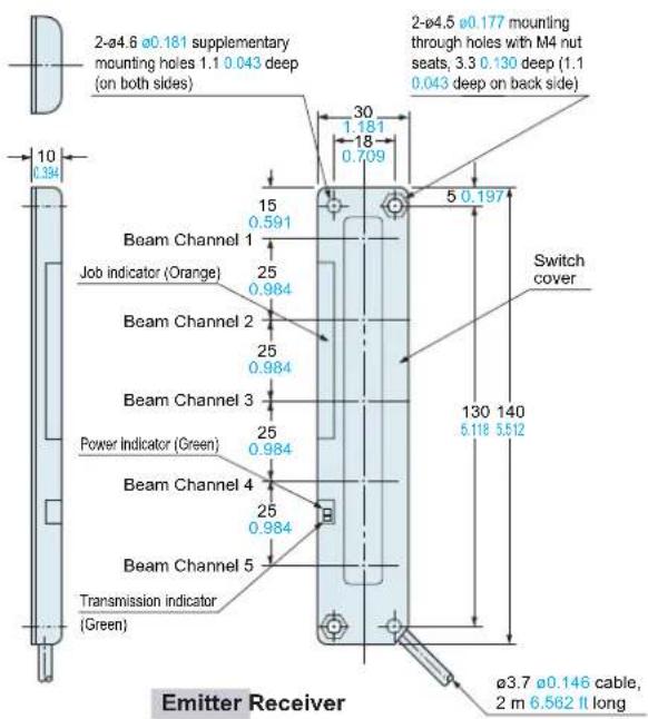
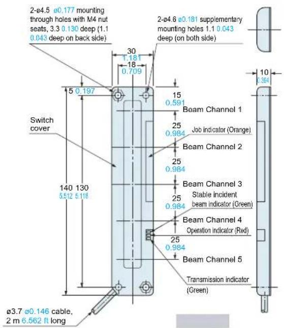
DIMENSIONS (Unit: mm in) The CAD data in the dimensions can be downloaded from the SUNX website: http://www.sunx.com
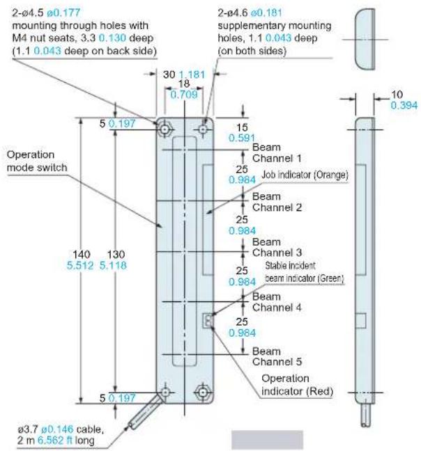
MS-NA1-1
Sensor mounting bracket (Optional)
Assembly dimensions
Mounting drawing with the receiver
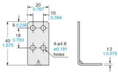
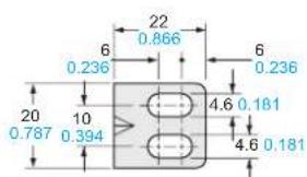
Material: Cold rolled carbon steel (SPCC) (Uni-chrome plated)
Four bracket set
Four M4 (length 15 mm 0.591 in) screws with washers, eight nuts, four hooks and eight M4 (length 18 mm 0.709 in) screws with washers are attached.
[M4 (length 18 mm 0.709 in) screws with washers are not used for NA1-PK5/5 series.]
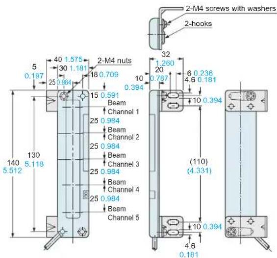
DIMENSIONS (Unit: mm in)
The CAD data in the dimensions can be downloaded from the SUNX website: http://www.sunx.com
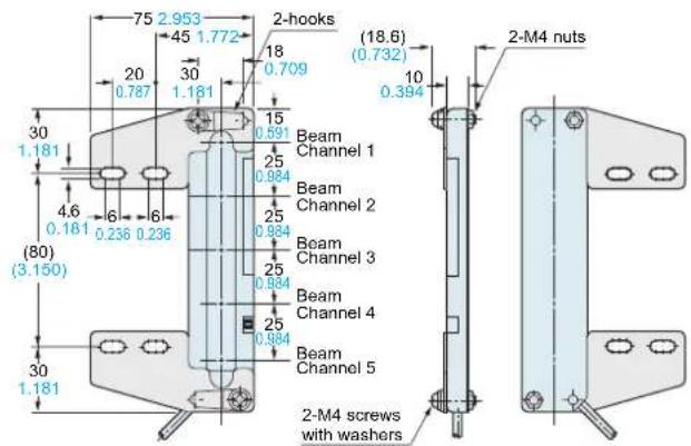
MS-NA2-1
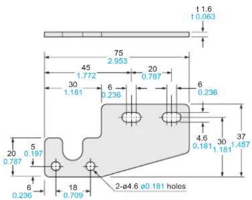
Material: Cold rolled carbon steel (SPCC) (Uni-chrome plated)
Four bracket set
Four M4 (length 15 mm 0.591 in) screws with washers, eight nuts, four hooks, four spacers and eight M4 (length 18 mm 0.709 in) screws with washers are attached.
Mounting drawing with the receiver
Sensor mounting bracket (Optional)
Assembly dimensions
MS-NA3 MS-NA3-BK
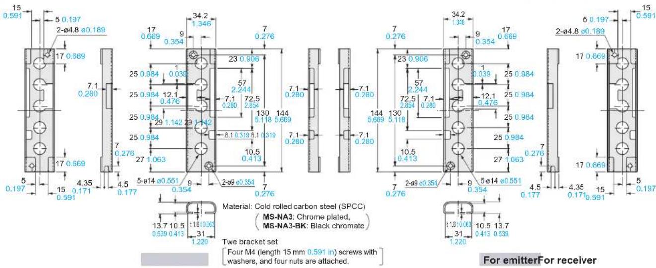
Sensor protection bracket (Optional)
SL-N15
S-LINK direct hook-up area sensor
- Ultra-slim Body Picking Sensor
- NA1-PK5 SERIES NA1-5 SERIES
- Even a slim hand is detected by the 25 mm 0.984 in pitch beam curtain
- mm 0.394 in thick: half the thickness of conventional models
- Clearly visible job indicator
- BASIC PERFORMANCE
- Long sensing range: 3 m 9.843 ft
- FUNCTIONS
- Two unit installations are possible
- APPLICATIONS
- Lighting pattern selectable
- Selectable detection operation
- ORDER GUIDE
- m 16.404 ft cable length type
- Pigtailed type
- S-LINK direct hook-up picking sensor
- OPTIONS
- Sensor mounting bracket
- Sensor protection bracket
- Slit mask
- Y-shaped connector
- I/O CIRCUIT AND WIRING DIAGRAMS
- NA1-PK5 NA1-5
- NPN output type
- NA1-PK5-PN NA1-5-PN
- PNP output type
- SENSING CHARACTERISTICS (TYPICAL)
- NA1-PK5 NA1-PK5-PN
- NA1-5 NA1-5-PN
- PRECAUTIONS FOR PROPER USE
- Mounting
- Orientation
- Interference prevention function
- LONG / SHORT selection switch (incorporated on the emitter)
- Selection of output operation
- Job indicator operation selection
- Others
- DIMENSIONS (Unit: mm in) The CAD data in the dimensions can be downloaded from the SUNX website: http://www.sunx.com
- Assembly dimensions
- DIMENSIONS (Unit: mm in)
Brand : PANASONIC
Model : NA1PK5PN
Category : Sensors