
N55 - Camcorder NIKON - Free user manual and instructions
Find the device manual for free N55 NIKON in PDF.


| Product Type | Digital Camcorder |
| Brand | Nikon |
| Model | N55 |
| Dimensions (W x H x D) | 4.5 x 3.0 x 2.5 inches |
| Weight | 1.2 lbs (with battery and memory card) |
| Power Supply | Rechargeable Lithium-Ion Battery (7.2V, 1200mAh) |
| Recording Media | SD/SDHC Memory Card (up to 32GB) |
| Video Resolution | 720 x 480 (Standard Definition) |
| Optical Zoom | 3x |
| Digital Zoom | 4x |
| Display | 2.5-inch Color LCD (230k dots) |
| Lens Aperture | f/1.8 - f/3.4 |
| Microphone | Built-in Stereo Microphone |
| Connectivity | USB 2.0, AV Output, HDMI Micro |
| Image Stabilization | Electronic (EIS) |
| Main Functions | Video recording, photo capture, play back, time-lapse, slow motion |
| Maintenance and Cleaning | Clean lens with a soft, dry microfiber cloth. Avoid using solvents. |
| Safety Precautions | Do not expose to water or extreme temperatures. Use only approved accessories. |
| Spare Parts and Repairability | Spare parts available through Nikon authorized service centers. Limited self-repair. |
| General Information | Designed for consumer video recording. Compatible with Windows and macOS. |
Frequently Asked Questions - N55 NIKON
User questions about N55 NIKON
0 question about this device. Answer the ones you know or ask your own.
Ask a new question about this device
Download the instructions for your Camcorder in PDF format for free! Find your manual N55 - NIKON and take your electronic device back in hand. On this page are published all the documents necessary for the use of your device. N55 by NIKON.
USER MANUAL N55 NIKON
Copyright © 2002 by Nikon Corporation
All Rights Reserved.
SPECIFICATION
- Viewfinder
| Type | : Hollow Pentagonal Type Single Lens Reflex Finder |
| Finder Screen | : B-type Clear Mat Screen V |
| Finder Replacement | : Unavailable |
| Screen Replacement | : Unavailable |
| Finder Visuality Ratio | : Approx. 87% both vertically and horizontally |
| Magnification | : 0.675 times at -1.52m-1(dpt)0.604 times at +0.77m-1(dpt)(50mm lens is used,∞) |
| Diopter | :-1.52 to +0.77m-1(dpt)Can be adjusted by the diopter adjustment lever, by 4-stepThe optional eyepiece correction lenses can be used together. |
| Eye Point | : 15.9mm (at -1.52m-1(dpt))23.1mm (at +0.77m-1(dpt))17.05mm (at -1m-1(dpt)) |
| Eyepiece Frame | : Rectangular Shape (F-401 type, new-eye eyepiece rubber is equipped.) |
| Eyepiece Lens | : 3 elements in 3 groups (Material; polycarbonate, acrylic) |
2. Shutter
①Electronically controlled vertical-travel focal-plane shutter
②Max. Shutter Speed 1/2000, At Synchronous Speed 1/90
③Curtain Speed Approx. 8msec (24mm Image plane)
④Traveling Direction Vertical-travel (Up)
⑤The Number of Blade Front curtain 4 elements Rear curtain 4 elements
⑥Material of Blade Aluminum Blade and Plastic Blade are used together
⑦Control Speed Range 30sec. to 1/2000sec., Time (M mode only)
3. Metering
①System TTL full-aperture exposure metering system by the IC integrated type five-segments sensor and TTL fill flash by CCD
②Control System With D-type Nikkor Lens: 3D five-segment Matrix Metering Without D-type Nikkor Lens: Five-segment Matrix Metering When the exposure mode is M: Center-Weighted Metering
③Metering Range EV1 to 20 (ISO 100, when using F1.4 lens)
④AE Lock No lock
4. Auto Flash
①System TTL-BL Fill-Flash by the IC integrated type sensor
②Range Built-in speed light:GN2.8 to 12 (ISO 100 m)
External speed light: External fill-flash only
③ISO Interlocking Range ISO 25 to 800 (Built-in/ External in common)
④Built-in Speed light Auto Flash System
Exposure Mode P, S, A, AUTO, Image program: TTL-BL
⑤Full Output Warning Ready-light in the finder blinks (For 3 to 4 sec.)
5. External Speed light
①Communication Serial communication is not available.
②Usable function with the external speed light
Shutter speed is changed to the synchronous shutter speed automatically
Ready-light display only
(But only when using the SB that can be recognized by the ready contact of camera.)
③Usable Mode Exposure Mode M, A: External auto-flash, Manual fill-flash
Exposure Mode Program Flash Mode: External auto-flash, Manual fill-flash
(When the exposure mode dial is at P, S, AUTO or Image Program, the
mode is changed automatically.)
④Red Eye Reduction Function
Pre-firing system by the red-eye reduction lamp (By the built-in lamp)
6. Built-in speed light
①Type Serial control type, Auto pop-up type
Auto pop-up, when it is low luminance while pressing the shutter release
button lightly at AUTO and Image Program Mode and when satisfying
the condition that the speed light pops up for the backlight.
The speed light pops up by operating the flash sync mode button at
PSAM modes, and the speed light fires compulsorily when the speed light pops up.
②Guide No. 12 (ISO 100·m)
③Illuminating Angle Cover the 28mm lens
④Charging Time Approx. 3 sec.
⑤Red Eye Reduction Function
Pre-firing System by the red-eye reduction lamp
- AF
| 1Detection System | TTL Phase Difference Detection System using AP-7 module |
| 2Detection Range | EV-1 to 19 (ISO100, at normal temperature) |
| 3Usable Lens for Detection | Maximum aperture value F5.6 or less |
| 4Usable Lens for Driving | AF Nikkor lenses except AF Nikkor for F3AF, AF-I and AF-S lens |
| 5Driving Mode | Auto-Servo AF Mode (AF-A)(Switch:EASYPSAM, AUTO, P.F>Image program exceptSports Continuos Mode DIFFICULT) |
| 6Tracking Drive | Single AF servo at Auto AF servo and Continuous Servo AF mode are available |
| 7Focus Lock | Focus is locked when the focus does not track at Single AF servoand the subject is in-focus.After the focus is locked, if it recognizes that the object is a moving body, it cancels the lock. |
| 8AF-Assist Illuminator | Auto firing onlyCancel the AF-Assist Illuminator at Landscape mode and Sports Continuous modeFunction that cancels the AF-Assistant Illuminator: UnavailableIt can perform the metering from approx. 0.5m to 3mFocusing time is the same as that of EV3 or brighter (Exclusive white and black chart, 20C)Assist illuminator of the body fires also when using the externalspeedlight with the assist illuminator. |
8. Program Diagram
When not using the speed light When using the built-in speed light
[1] Auto-Multi Program Mode (P) and AUTO Mode (AUTO)

In the control diagram, the limit of the control aperture value at the aperture side is mentioned 1.4, but on the control, the aperture value is available up to 1.0 and the limit is not made. (Since no lens of which aperture value is more than 1.4 can be controlled, the aperture value more than 1.4 is not mentioned in the diagram.)
[2] Portrait Mode (2)

line
| Shutter Speed | Aperture value | | ------------- | -------------- | | 30" | 2.8 | | 60 | 2.8 | | 125 | 2.8 | | 2000 | 2.8 |[3] Landscape Mode ( )

line
| Shutter Speed | Aperture value | | ------------- | -------------- | | 30" | 1.4 | | 60 | 2.8 | | 125 | 8 | | 2000 | 32 |[4] Close-Up Mode ( )

line
| Shutter Speed | Aperture value | | ------------- | -------------- | | 30" | 1.4 | | 125" | 5.6 | | 2000 | 32 |DISASSEMBLING
1. SEPARATION OF THE FRONT BODY FROM THE REAR BODY
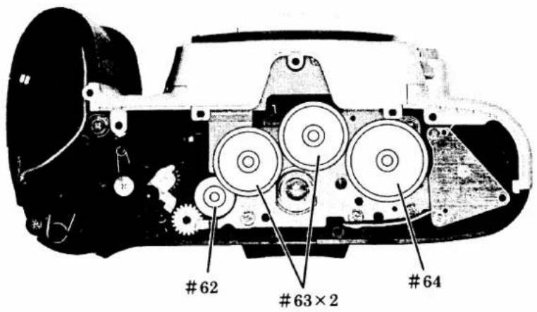
BOTTOM COVER D 1
BACK DOOR D 2
FRONT COVER, GRIP COVER D 3
TOP COVER D 4
SEPARATION OF THE FRONT AND REAR BODY D 5
2. FRONT BODY
SHUTTER D 7
LCD DISPLAY D 8
MAIN PCB D 8
AF SENSOR UNIT D 9
REMOVE THE WIRES AND SOLDERING BRIDGES D 9
APERTURE CONTROL BASE PLATE D 10
APERTURE CONTROL LEVER D 10
HORIZONTAL AF LEVER UNIT, F min SW D 1 1
SB/BKTSWFPC, LENS RELEASE GROUP D11
LEVER#191, A/M SW D 1 2
TTL FPC UNIT D 1 2
AF DRIVING UNIT D 1 3
BAYONET MOUNT D 1 3
LENS CONTACT D 1 4
MIRROR HOLDER D 1 4
PENTAPRISM GROUP D15
3. REAR BODY
SB UNIT, DC/DC UNIT, SUB PCB D 1 6
COMMAND DIAL, DX CONTACT D 1 6
BOTTOM BASE PLATE D 17
FILM ADVANCE UNIT D 17
SMALL PARTS REAR BODY D 1 8
DISASSEMBLING/ASSEMBLING/ADJUSTMENT
| WARNING | |
 | ●Due to its internal high voltage area, make sure to check the safety when removing the cover.●Be sure to discharge the static electricity from the main condenser according to the instruction in the repair manual after removing the Grip cover. |
Note : ①This repair manual is made by using a product manufactured for trial, therefore, some part might be different from those of the mass production product.
Arrangement of wires might be changed depending on the period of manufacturing.
②Be sure to take off the battery before disassembly.
③At disassembly, make sure to memorize how to arrange the wires, how to fix the screws, and the types of used screws.
④Be sure to get yourself grounded because of the static electricity which exerts any serious adverse effect to ICs.
⑤When you disassemble the camera body further than described in the disassembling section, refer to the exploded drawings and assembling section, since some parts are disassembled as a unit part.
DISASSEMBLING
1. SEPARATION OF THE FRONT BODY FROM THE REAR BODY
BOTTOM COVER


- Remove the gears indicated in Figure on the left.
BACK DOOR
Notes: Never use the solvent when cleaning the pressure plate, but use the A-level dust cleaning cloth or Savina Minimax and wipe it softly because the pressure plate of this camera is coated with the special paint.

- Remove the screw #656, and then remove the camera back as shown in Picture below.
FRONT COVER, GRIP COVER
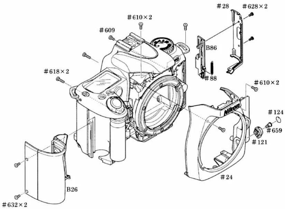
Discharging from the main capacitor
• After discharging electricity, unsolder the pink and blue wires, and then remove the main condenser.

For the discharge a resistance of approx 2kΩ/5W should be used.
TOP COVER


- With removing the top cover, the eyepiece frame can be removed.
SEPARATION OF THE FRONT AND REAR BODY
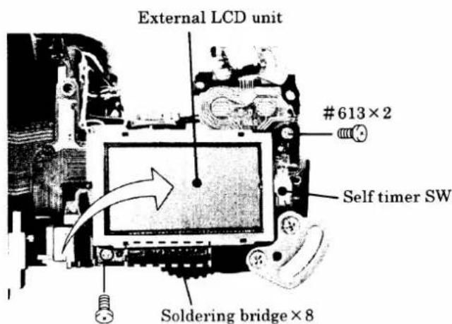
Removal each wires and solder bridges


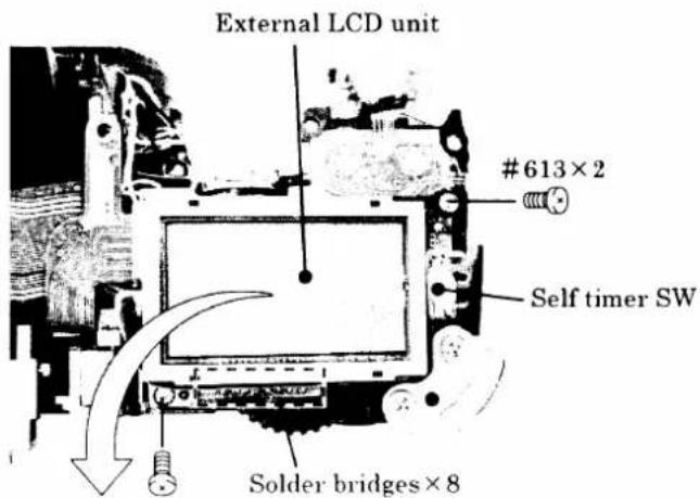
Note : Remove the FPC of the self-timer SW first, and then lift up the external LCD unit in an arrow direction.

- Remove the FPC of the main PCB from the connector.


2. FRONT BODY
SHUTTER

①Remove the wires of the shutter.
②Rotate the gear #215 in an arrow direction to make the mirror up

- After removing the shutter, rotate the gear #215 to make the mirror down.
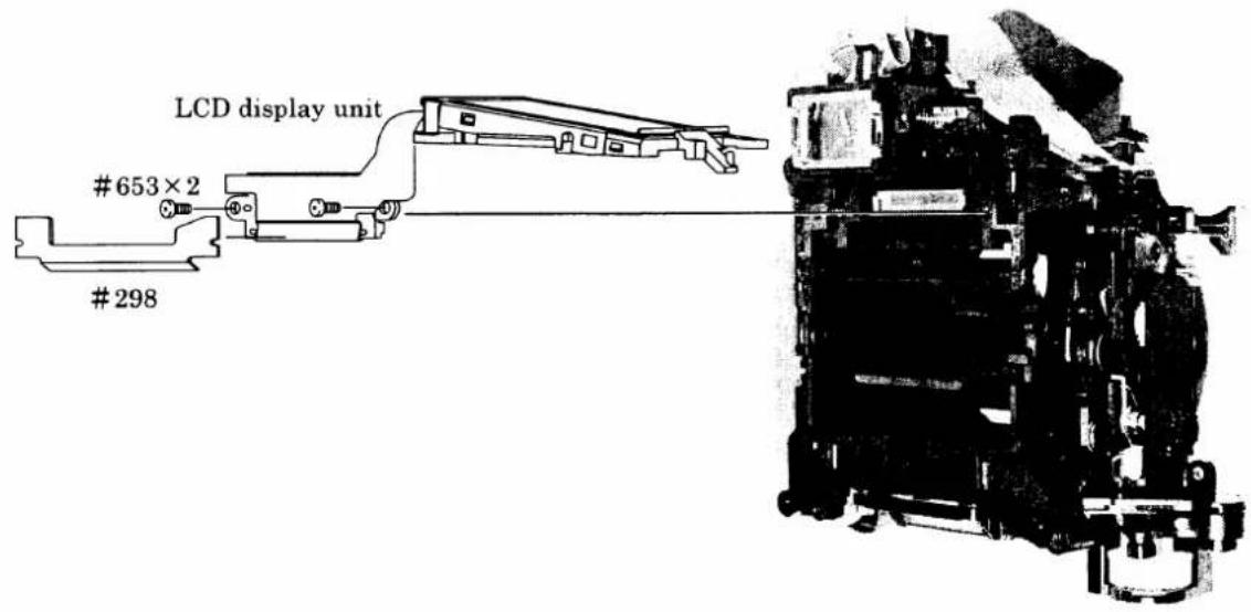
LCD DISPLAY UNIT
MAIN PCB


AF SENSOR UNIT

REMOVE THE WIRES AND SOLDERING BRIDGES

APERTURE CONTROL BASE PLATE

APERTURE CONTROL LEVER

HORIZONTAL AF LEVER UNIT, F min SW
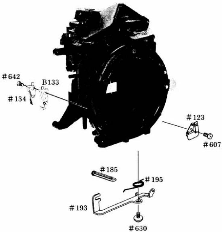
SB/BKTSWFPC, LENS RELEASE GROUP

LEVER#191、A/M SW

TTL FPC UNIT

AF DRIVING UNIT

BAYONET MOUNT

LENS CONTACT

MIRROR HOLDER
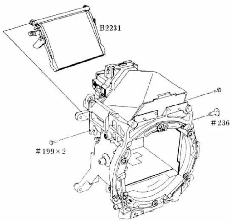
PENTAPRISM GROUP
Note : Since the prism of this camera is plastic hollow type, when cleaning inside the prism, blow inside the prism by using the brower.

3. REAR BODY
SB UNIT. DC/DC UNIT. SUB PCB

COMMAND DIAL. DX CONTACT


BOTTOM BASE PLATE

FILM ADVANCE UNIT
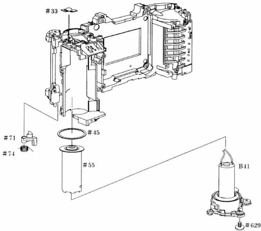

ASSEMBLING/ADJUSTMENT
1. FRONT BODY
MIRROR HOLDER A 1
APERTURE CONTROL LEVER, F min SW A 2
APERTURE CONTROL BASE PLATE A 3
AF DRIVING UNIT A 4
LEVER#191, A/M SW A 4
HORIZONTAL AF LEVER A 5
BAYONET MOUNT A 5
LENS RELEASE BUTTON GROUP A 6
HIGHT ADJUSTMENT OF AF COUPLING SHAFT A 6
ADJUSTMENT OF APERTURE LEVER POSITION A 7
TTL FPC UNIT A 7
AF SENSOR UNIT A 8
SB/BKTSWFPC A 8
MAIN PCB A 9
ANGLE ADJUSTMENT OF MAIN MIRROR AND SUB MIRROR TO 45° A 10
LCD DISPLAY UNIT A11
SHUTTER A 1 1
EYEPIECE LENS UNIT A 1 2
PENTAPRISM GROUP A 1 2
AE SPD POSITION ADJUSTMENT A 1 3
2. REAR BODY
SMALL PARTS REAR BODY A 1 4
FILM ADVANCE UNIT A 1 4
COMMAND DIAL, DX CONTACT A 1 5
SB UNIT, DC/DC UNIT, SUB PCB A 1 6
BOTTOM BASE PLATE A 1 6
3. MOUNTING BOTH THE FRONT AND REAR BODY
MOUNT THE FRONT BODY TO THE REAR BODY A 17
INSPECTION & ADJUSTMENT OF BODY BACK A 17
BACK DOOR OPEN/CLOSE AREA A 19
TOP COVER A 1 9
MAIN CONDENSER A 2 2
FRONT COVER, GRIP COVER A 2 2
ADJUSTMENT THROUGH PC A 2 3
AF/AE ADJUSTMENT A 2 4
BACK DOOR A 2 5
BOTTOM COVER A 2 6
ADJUSTMENT OF OPENING IN SB PART A 2 6
ASSEMBLING/ADJUSTMENT
1. FRONT BODY
MIRROR HOLDER
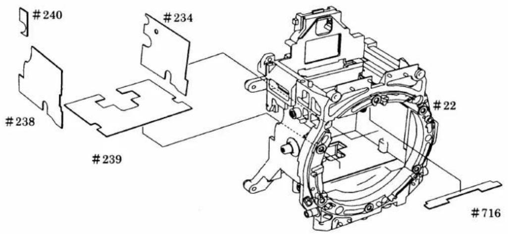

Note : Stand the mirror up and assemble the sub-mirror deflection pin#236 into the front body#22.

APERTURE CONTROL LEVER, F min SW


· Order of setting springs
Set the springs in order of #260
- #205 - #212 - #213.
APERTURE CONTROL BASE PLATE
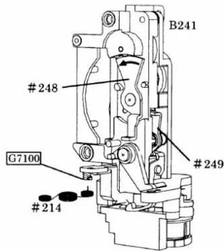
①Set the spring #214.
②Move the lever #248 in an arrow direction to touch the limit.
③Push the #249 to lock the lever #248.
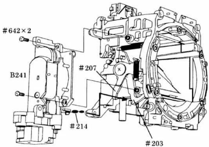
④Attach B241 so that the spring #214 comes between the mirror up laver #203 and #207.

AF DRIVING UNIT

LEVER #191, A/M SW

- Order of attaching
B116-#122-#191-#630
B125-#126-#642-#123
-#607
HORIZONTAL AF LEVER UNIT

BAYONET MOUNT
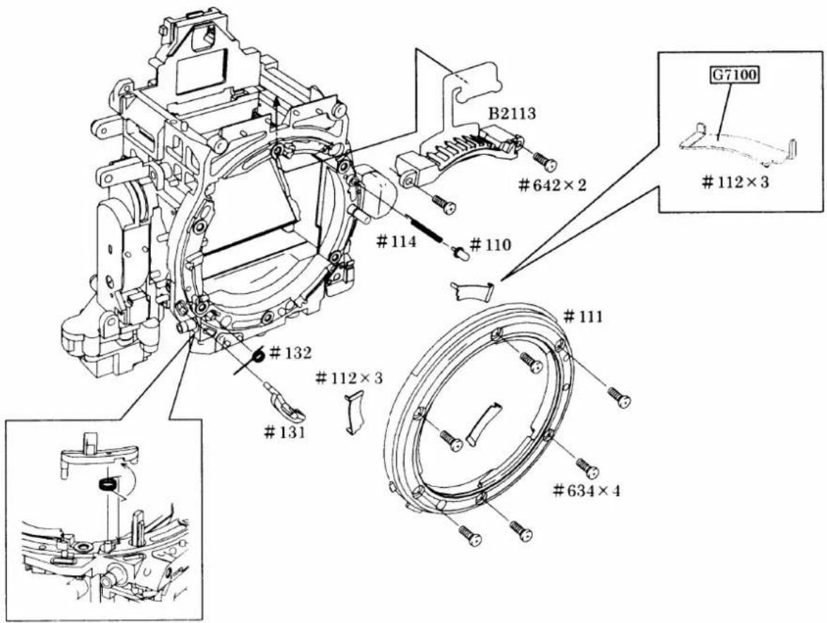
LENS RELEASE BUTTON GROUP
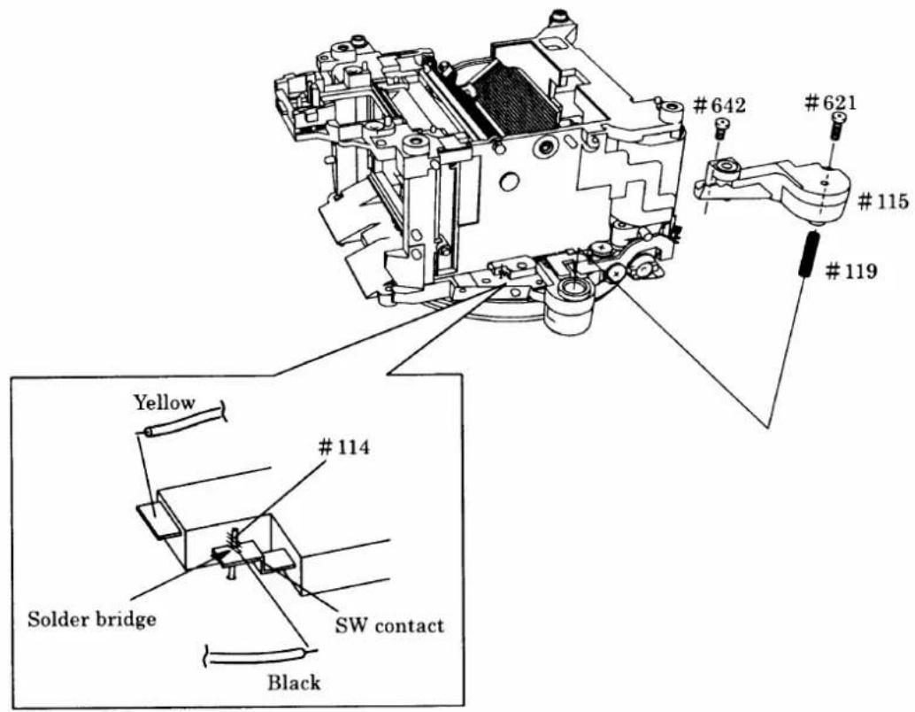
HIGHT ADJUSTMENT OF AF COUPLING SHAFT


①Set the A/M change-over cam #122 to "AF". After pressing the lens quick-disconnect button two or three times, measure the height of the AF coupling shaft #185.
②Adjust the height of the AF coupling shaft using screw #625.
③The AF coupling shaft should not protrude over the lens mount surface. when the height of lens release pin is adjusted to 0.4mm.
④After adjusting, secure screw #625 using Screw Lock.
ADJUSTMENT OF APERTURE LEVER POSITION

●Measure the height of the aperture lever using tool J18004.
Standard value: 3.4±0.1mm
If the height of the aperture lever is out of the standard value, bend the circled position to adjust. While adjusting, take care not to bend the inside lever and stopper portion.
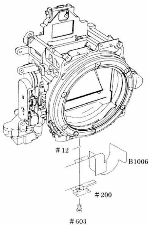
TTL FPC UNIT
AF SENSOR UNIT
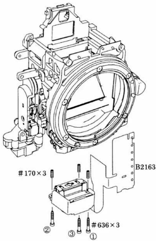
- Tighten the screw #636×3 in order of ① to ③ by the hex key to the end, and then rotate them about 2 revolutions back.
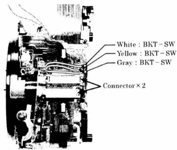
SB/BKTSWFPC

MAIN PCB



ANGLE ADJUSTMENT OF MAIN MIRROR AND SUB MIRROR TO 45°

\*Use tools
-
Angle inspection of main mirror
①Collimator (J19002)
②Mirror angle inspection mirror (J15391)
③Optical parallel (J18037) -
Angle adjustment of sub mirror
①Collimator (J19002)
②Sub mirror angle adjustment tool (J18268-1)
③Hexagonal Wrench
●Angle inspection of the main mirror to 45°
Note : This camera does not have an eccentric pin for the main mirror.
- If the difference on the top, bottom, right and left is out of standard, the mirror unit B2231 might be defective or the mirror shaft might be bended.
●Angle adjustment of the sub mirror to 45^
Note : Check accuracy by moving the main mirror up and down for a few times before and after the adjustment.
- Check the difference on the top and bottom. If it is out of standard, adjust the angle by rotating the eccentric pin for sub mirror.
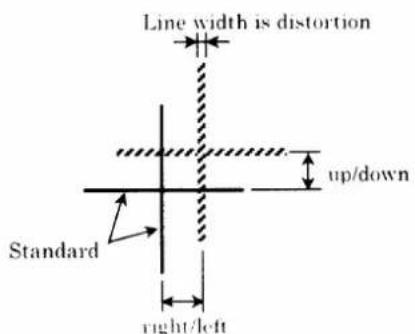
Standard :
| Main mirror | Sub mirror | |
| Discrepancy(right/left) | Within ± 20' | |
| Discrepancy(up/down) | Within ± 15' | Within ± 5' |
| Distortion | Within ± 8' | Within ± 8' |
LCD DISPLAY UNIT

SHUTTER

①Attach the light baffle plate #298.
②Rotate the gear #215 in an arrow direction to make the mirror up.
③Attach the shutter.
④Rotate the gear #215 to make the mirror down.
Note : After adhesive becomes completely dry, attach the shutter.
EYEPIECE LENS UNIT
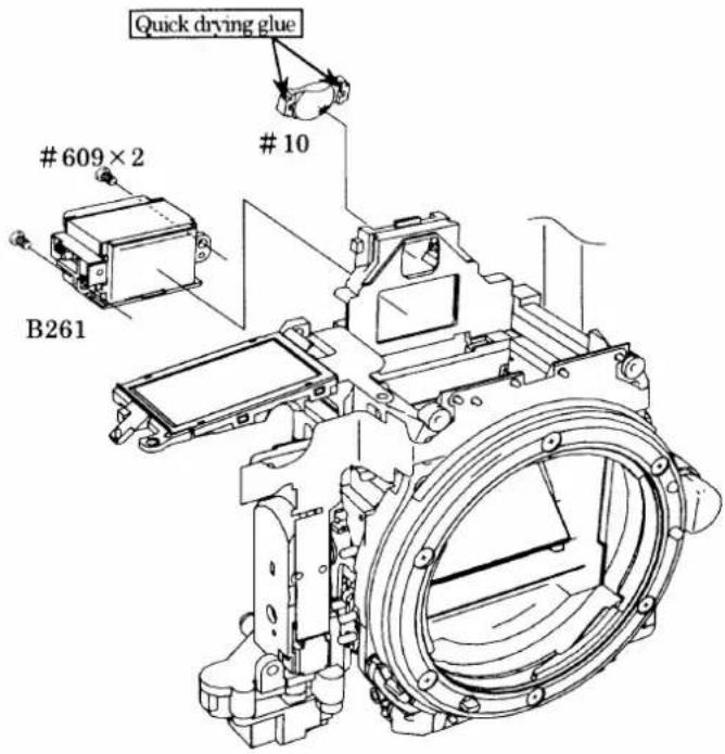
PENTAPRISM GROUP

AE SPD POSITION ADJUSTMENT
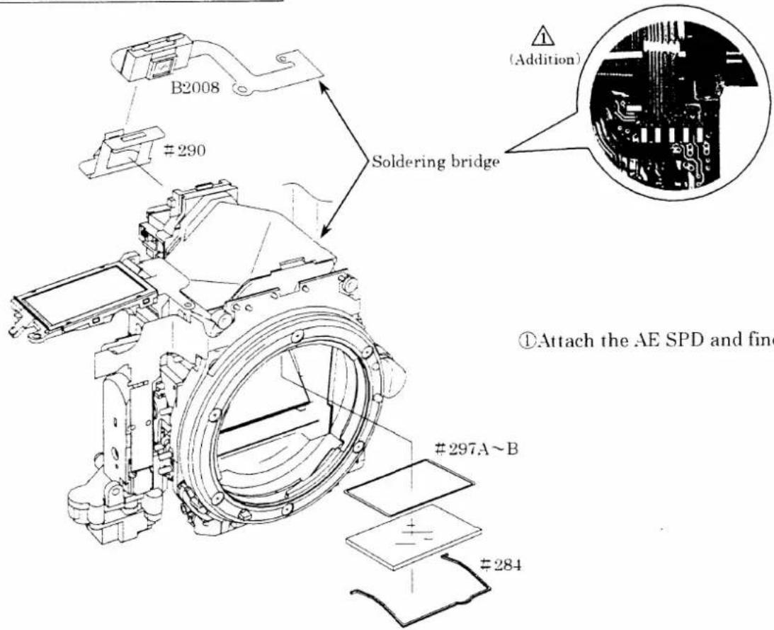
①Attach the AE SPD and finder screen.
②Shade the eyepiece lens and the shutter side of the mirror box by using a piece of black tape, etc.
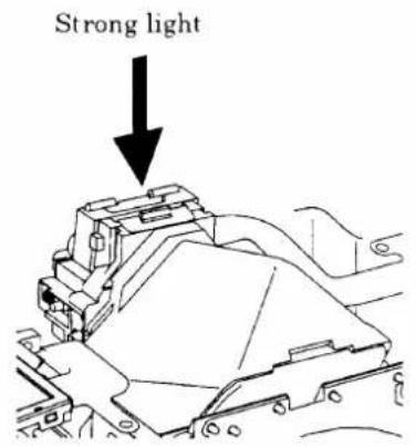
③Give strong light from the upper side of the AE SPD as shown. Figure on the left to reflect the patter of AE SPD on the main mirror.
④Set the focus frame of the screen and the pattern of AE SPD as shown in Figure below:


flowchart
graph TD
    A["C"] --> B["["]]
    B --> C["C"]
⑤ Fix the AE SPD holder to the mirror box with quick dry glue.

2. REAR BODY
SMALL PARTS REAR BODY
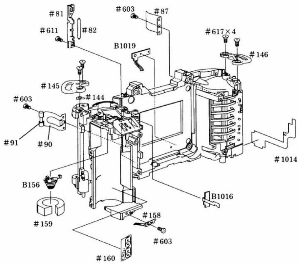
FILM ADVANCE UNIT

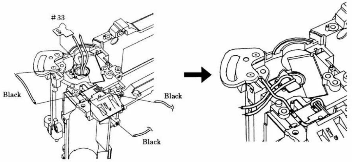
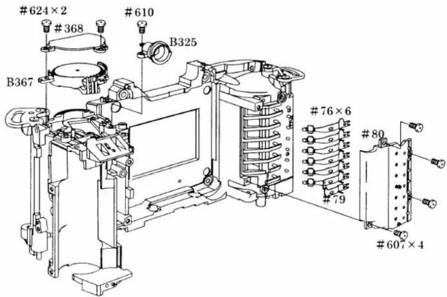
COMMAND DIAL, DX CONTACT
SB UNIT, DC/DC UNIT, SUB PCB
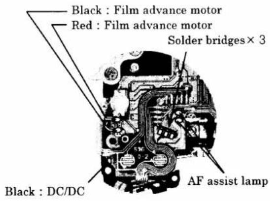
Note : AF assist lamp does not have polarity.


BOTTOM BASE PLATE

3. MOUNTING BOTH THE FRONT AND THE REAR BODY
MOUNT THE FRONT BODY TO THE REAR BODY
- Tighten the screws in order of ①-⑩.

Note : The indicated washers #888 are the standard ones for each position.
INSPECTION & ADJUSTMENT OF BODY BACK
Note : Take note (A) to (D) in order to the difference from the standard 46.67mm at AF adjustment after inspection and adjustment.

●Measure between the bayonet surface and the outer rail.
× marking: Where to be measured
Standard: 46.64±0.06mm/Tolerance for flatness: within 0.06mm
- If the measured value is out of standard, perform the adjustment by moving the front body and rear body by unfastening the screws on them.
Or adjust it by the washers between the front body and rear body.
Connector, Soldering bridges



BACK DOOR OPEN/CLOSE AREA

TOP COVER

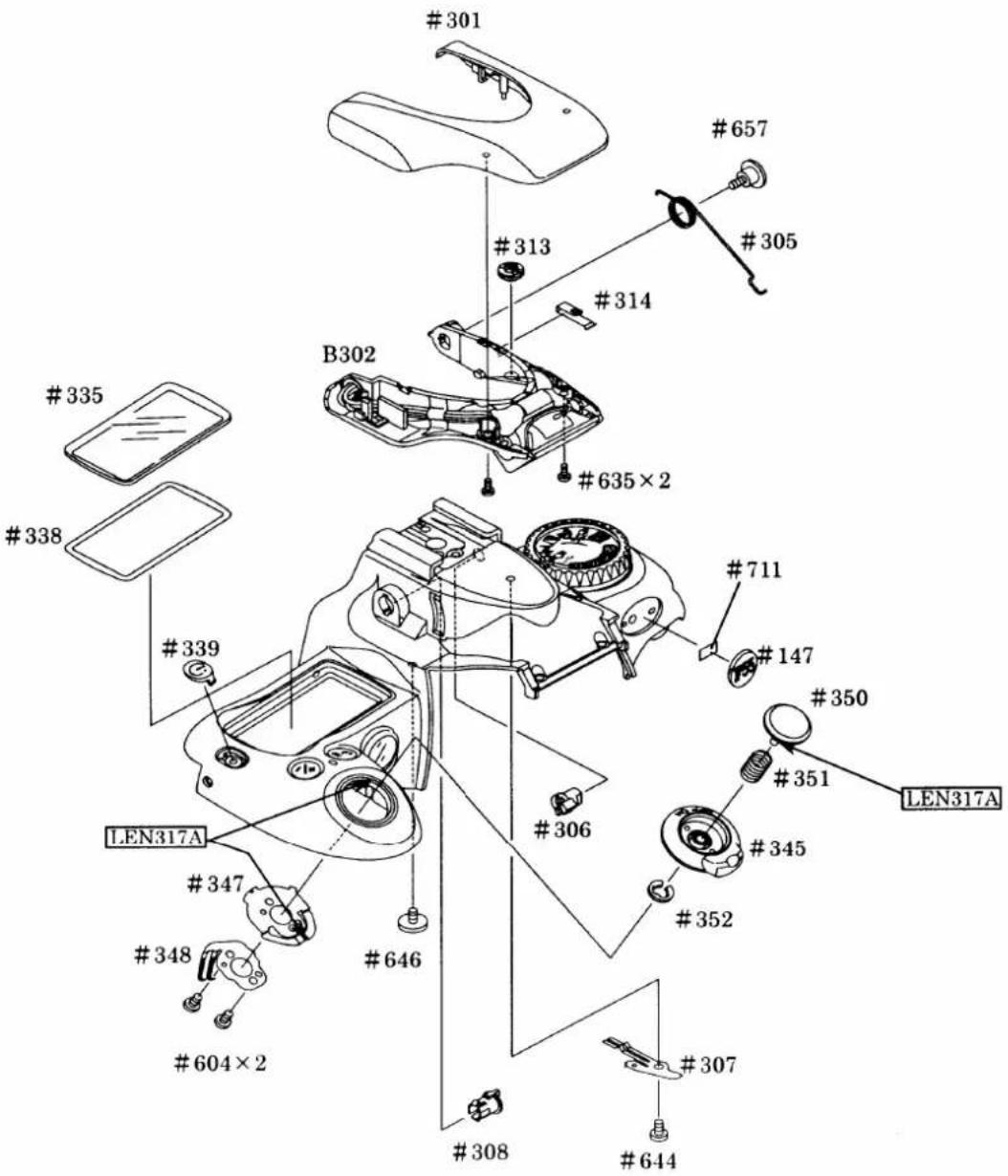

※When attaching the top cover, assemble the eyepiece frame, too.

MAIN CONDENSER
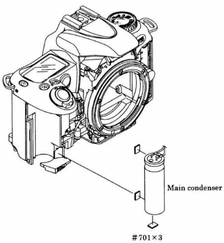

FRONT COVER, GRIP COVER

ADJUSTMENT THROUGH PC
9pin-25pin adapter is necessary for a computer with 9pin RS-232C terminal. RJ is not available.
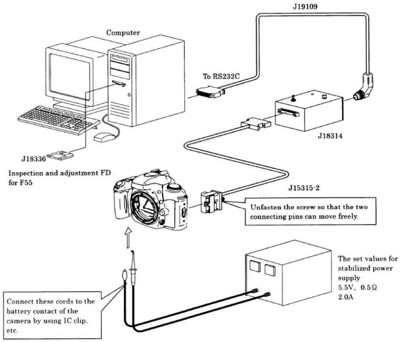
flowchart
graph TD
    A["Computer"] -->|J18336| B["Inspection and adjustment FD for F55"]
    A -->|J19109| C["J18314"]
    C --> D["J15315-2"]
    D --> E["Unfasten the screw so that the two connecting pins can move freely."]
    E --> F["The set values for stabilized power supply 5.5V, 0.5Ω 2.0A"]
    F --> G["Connect these cords to the battery contact of the camera by using 1C clip, etc."]
    G --> H["To RS232C"]
AF/AE ADJUSTMENT
Note: ①Be sure to perform the AF adjustment first, then perform the AE adjustment.
②When using this adjustment software for the first time, prepare 5 units of F55 cameras to measure and obtain the average value of them at the AF accuracy inspection. Then input the average value of these measured 5 units in "WRITING OF AF ADJ. LENS OFFSET VALE" "in the main menu.
※If there is lens data for adjustment of F65, it is possible to make a file for F55 from the file for F65 at "WRITING OF AF ADJ. LENS OFFSET VALUE" in the menu of adjustment software.
• AF ADJUSTMENT
[Inspection and adjustment items]
①Inspection and adjustment for the AF accuracy (whole item shall be adjusted)
②YAW, PITCH
③LARK adjustment (include CCD output)
④MBF adjustment
[Tool in use]
- For adjustment of whole item:
The tool(s) used for the AE-oriented adjustment shall be utilized.
- For check of the AF accuracy
①Z adjustment lens (J18266) for F5, F100, F80
②AF adjustment stand (J15259)
③Z lens holder (J15280) or position conversion adapter (J15271) for tripod socket
④AF chart (J18273) for F5, F100, F80
⑤Lighting box (J15264) for high frequency
- For adjustment of YAW, and PITCH
①The whole tool used for the check of AF accuracy just as mentioned above
②Adjustment tool for YAW, and PITCH (J18230)
- For adjustment of LARK (include CCD output adjustment)
①The whole tool used for the check of AF accuracy just as mentioned above
②AF 50/1.4D lens
· AE adjustment
- AE adjustment
- Aperture adjustment
- M 1/2000 adjustment
- TTL adjustment
- Battery check adjustment
Note : Be sure to utilize either "F90" or "N90" oriented camera's shutter curtain.
Confirmation of the Battery check display mode
After adjusting the battery check, input below-mentioned each voltage data to the camera and then check the external LCD mode.
Note : Conduct the inspection by switching each voltage in order of No.1 to 5.
| External LCD mode | Set up voltage from the stabilized power supply | |
 | 1 5.00V | 5 5.30V±0.2V |
 | 2 4.80V±0.2V | 4 5.00V±0.2V |
 blinks blinks | 3 4.50V±0.2V | |
BACK DOOR
Note : Never use the solvent when cleaning the pressure plate, but use the A-level dust cleaning cloth or Savina Minimax and wipe it softly because the pressure plate of this camera is coated with the special paint.
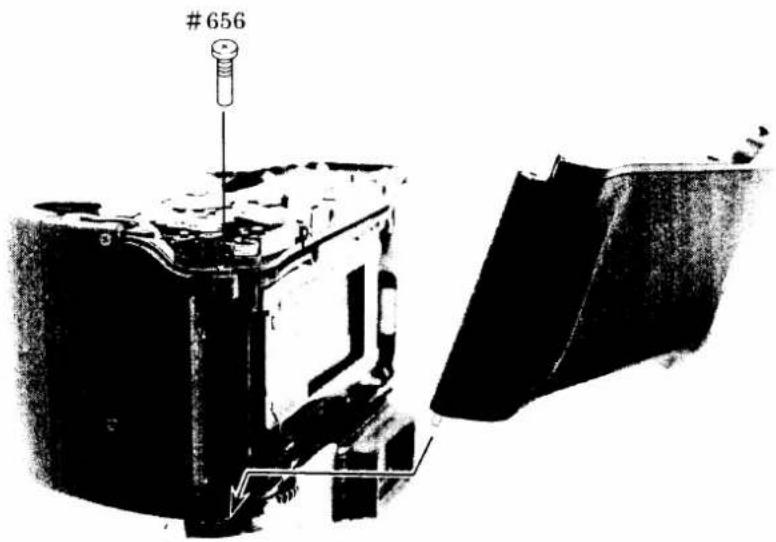
BOTTOM COVER

ADJUSTMENT OF OPENING IN SB PART

- When pressing the SB part from the top, if play or opening is big, adjust the opening by making the SB part pop up and rotate the #313 by the hex key.
ELECTRIC CIRCUIT
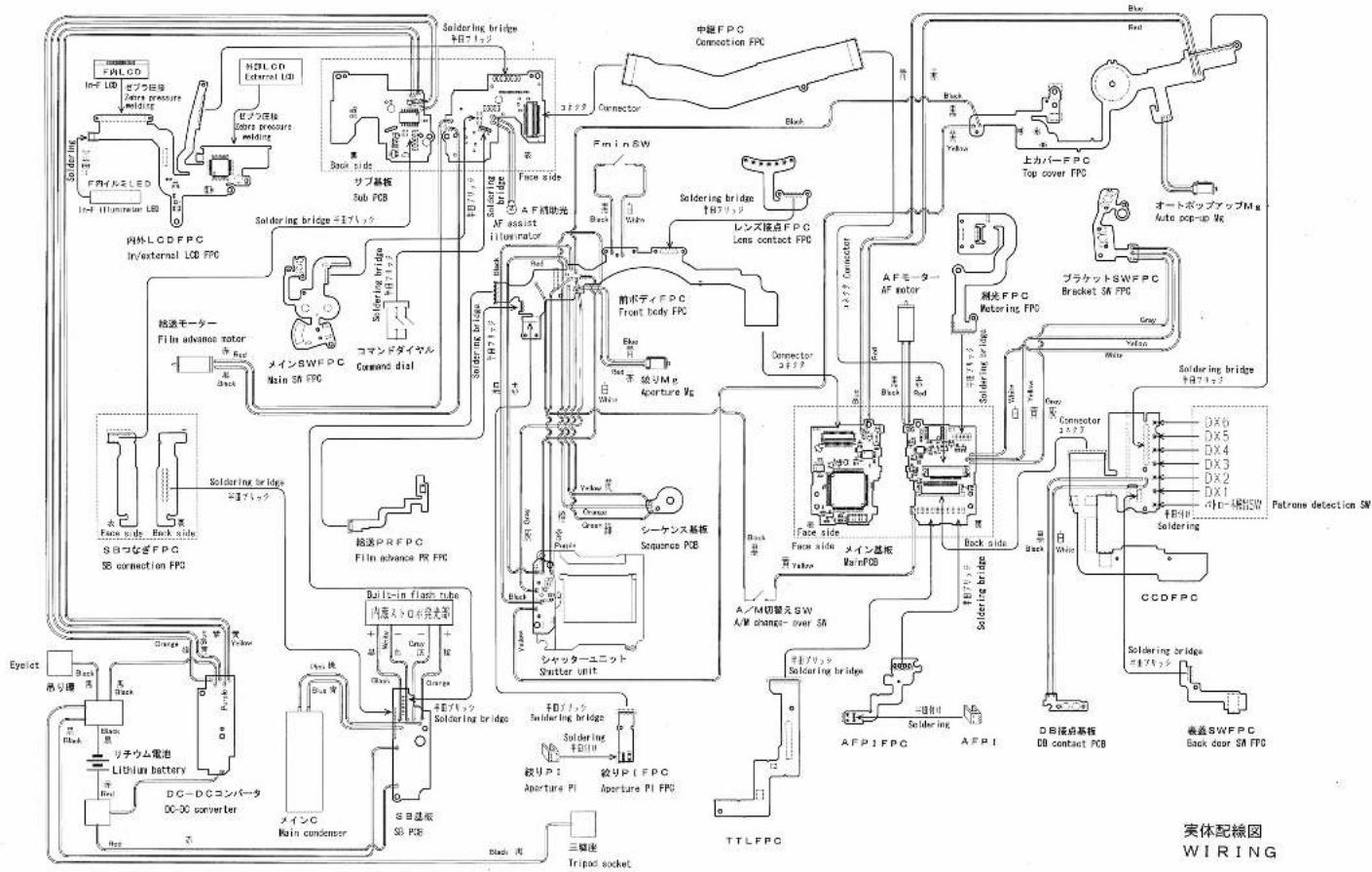
WIRING E 1
CIRCUIT DIAGRAM E 2
MAIN PCB E 3
SUB PCB E7
CCDFPC E11
TTL FPC E 1 2
TOP COVER FPC E 1 3
METERING FPC E 1 4
FRONT BODY FPC E 15
IN/EXTERNAL LCD FPC E 1 6
MAIN SW FPC E 18
AFPI FPC E20
LENS CONTACT FPC E 2 1
BACK DOOR SW FPC E 2 2
SB CONNECTION FPC E 2 3
FILM ADVANCE FPC E 2 4
APERTURE PI FPC E 2 5
DATABACK FPC E26
DB CONTACT FPC E 27
BRACKET SW FPC E28
EEPROM DATA E 2 9
FAA39001-R.3568.A
flowchart
graph TD
    A["MCU M150/62 U1"] --> B["Bracket 5V FPC"]
    A --> C["Main PCB"]
    A --> D["Sub PCB"]
    A --> E["Neural LCD Panel"]
    A --> F["Neural LCD Panel"]
    A --> G["Neural LCD Panel"]
    A --> H["Neural LCD Panel"]
    A --> I["Neural LCD Panel"]
    A --> J["Neural LCD Panel"]
    A --> K["Neural LCD Panel"]
    A --> L["Neural LCD Panel"]
    A --> M["Neural LCD Panel"]
    A --> N["Neural LCD Panel"]
    A --> O["Neural LCD Panel"]
    A --> P["Neural LCD Panel"]
    A --> Q["Neural LCD Panel"]
    A --> R["Neural LCD Panel"]
    A --> S["Neural LCD Panel"]
    A --> T["Neural LCD Panel"]
    A --> U["Neural LCD Panel"]
    A --> V["Neural LCD Panel"]
    A --> W["Neural LCD Panel"]
    A --> X["Neural LCD Panel"]
    A --> Y["Neural LCD Panel"]
    A --> Z["Neural LCD Panel"]
    A --> AA["Neural LCD Panel"]
    A --> AB["Neural LCD Panel"]
    A --> AC["Neural LCD Panel"]
    A --> AD["Neural LCD Panel"]
    A --> AE["Neural LCD Panel"]
    A --> AF["Neural LCD Panel"]
    A --> AG["Neural LCD Panel"]
    A --> AH["Neural LCD Panel"]
    A --> AI["Neural LCD Panel"]
    A --> AJ["Neural LCD Panel"]
    A --> AK["Neural LCD Panel"]
    A --> AL["Neural LCD Panel"]
    A --> AM["Neural LCD Panel"]
    A --> AN["Neural LCD Panel"]
    A --> AO["Neural LCD Panel"]
    A --> AP["Neural LCD Panel"]
    A --> AQ["Neural LCD Panel"]
    A --> AR["Neural LCD Panel"]
    A --> AS["Neural LCD Panel"]
    A --> AT["Neural LCD Panel"]
    A --> AU["Neural LCD Panel"]
    A --> AV["Neural LCD Panel"]
    A --> AW["Neural LCD Panel"]
    A --> AX["Neural LCD Panel"]
    A --> AY["Neural LCD Panel"]
    A --> AZ["Neural LCD Panel"]
    A --> BA["Neural LCD Panel"]
    A --> BB["Neural LCD Panel"]
    A --> BC["Neural LCD Panel"]
    A --> BD["Neural LCD Panel"]
    A --> BE["Neural LCD Panel"]
    A --> BF["Neural LCD Panel"]
    A --> BG["Neural LCD Panel"]
    A --> BH["Neural LCD Panel"]
    A --> BI["Neural LCD Panel"]
    A --> BJ["Neural LCD Panel"]
    A --> BK["Neural LCD Panel"]
    A --> BL["Neural LCD Panel"]
    A --> BM["Neural LCD Panel"]
    A --> BN["Neural LCD Panel"]
    A --> BO["Neural LCD Panel"]
    A --> BP["Neural LCD Panel"]
    A --> BQ["Neural LCD Panel"]
    A --> BR["Neural LCD Panel"]
    A --> BS["Neural LCD Panel"]
    A --> BT["Neural LCD Panel"]
    A --> BU["Neural LCD Panel"]
    A --> BV["Neural LCD Panel"]
    A --> BW["Neural LCD Panel"]
    A --> BX["Neural LCD Panel"]
    A --> BY["Neural LCD Panel"]
    A --> BZ["Neural LCD Panel"]
メイン PCB
MAIN PCB
FAA39001-R. 3568.A
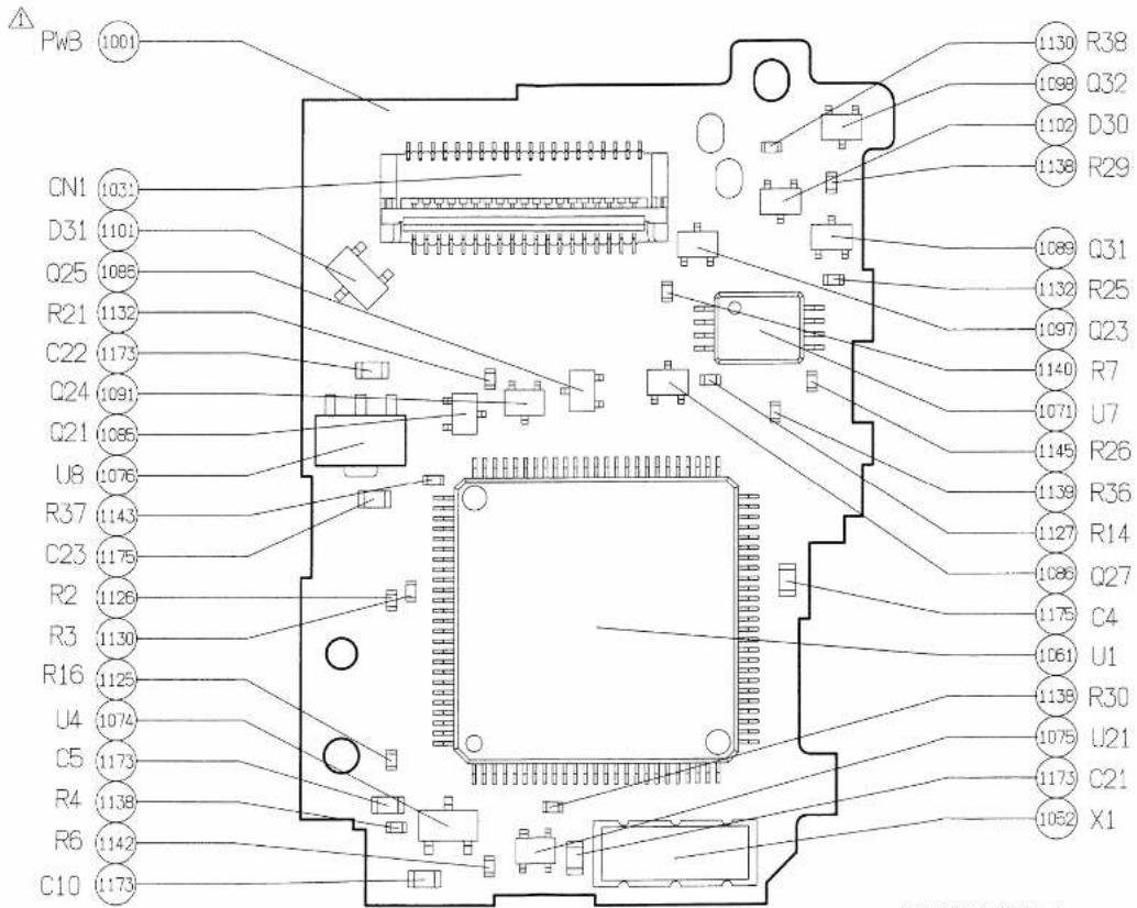
表面部品実装図
Front side parts location's diagram
FAA39001-R. 3568. A
メイン PCB MAIN PCB

裏面部品実装部
Back side parts location's diagram
メイン PCB
MAIN PCB
FAA39001-R. 3568. A

Front side parts location's diagram
FAA39001-R. 3568. A
サブ PCB
SUB PCB

裏面部品実装部
Back side parts location's diagram
FAA39001-R. 3568.A
サブ PCB
SUB PCB

裏面ランド名称入りパターン図
Back side pattern diagram with land name
CCD FPC

natural_image
Pure electrical circuit lines without any symbolsFront side parts location's diagram
内外LCD FPC
IN/EXTERNAL LCD FPC
FAA39001-R. 3568. A

natural_image
Pure electrical circuit lines without any symbolsFront side pattern diagram with land name
裏蓋SW FPC
BACK DOOR SW FPC
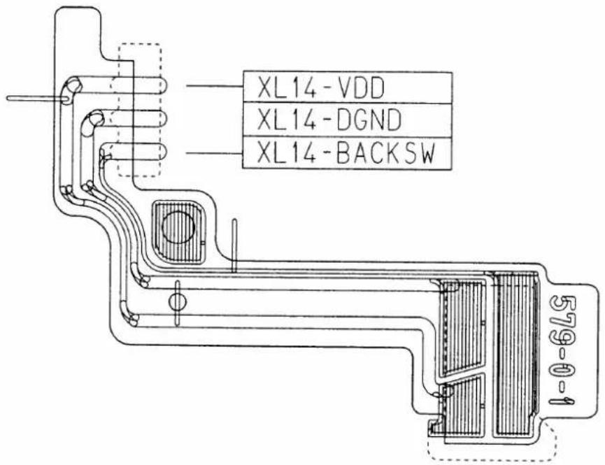
表面ランド名称入りパターン図
Front side pattern diagram with land name
SBつなぎFPC
SB CONNECTION FPC

Front side pattern diagram with land name

[1] Inspection Criteria R 1
[2] Tools T 1
CONDITION FOR INSPECTION
Normal temperature: 20 ± 5^ C
Humidity: 65 ± 20%
Power source : 5.5 ± 0.03 V
5 A or more at 0.5 Ω load
Light source : 2856° K
K coefficient : 1.16
Camera : Finished Product
INSPECTION CRITERIA
●When using the power supply, set the output to 5.5V with a resistance of 0.5Ω.
| INSPECTION ITEM | CRITERIA | REMARKS |
| Shutter System(1)Tolerance(2)Curtain Speed(3)Dispersion(4)Curtain Bound | 1/2000~1/1500: 0±0.45EV1/1500~30s: 0±0.3EV6.9ms or less1/2000~1/180: Within 0.45EV1/180~30s: Within 0.3EVThere should be on curtain bound. | Exposure Mode : M, SShutter tester (EF-8000)21mm |
| AE Image Surface Exposure(1)Tolerance | 1/2000~1/125: ±0.65EVless than 1/125: ±0.5EV | Exposure Mode : P,A,SShutter tester (EF-8000)AF50/1.4D |
| AE Diaphragm Control Accuracy(1)Tolerance(2)Dispersion | LV12 (ISO 100)、1/125From the maximum aperture to 4th stop aperture: ±0.5EVFrom F8 to the minimum aperture: ±0.65EVWithin 0.5EV | Exposure Mode : SShutter tester (EF-8000)AF50/1.4D |
| AF Adjustment Accuracy(1)Yaw(2)Pitch(3)Lark | Center: 0±4mradSide: 0±10mradCenter: 0±5mradSide: 0±10mrad0±50μm | Personal Computer and other special tools |
| Diaphragm Lever Height | 3.4±0.1mm | J18004 |
| Main Mirror 4 5°(Collimator Measured Value) | Upper/Lower: ±15'Right/Left: ±30'Distortion: Within 8' | When it is stood up, there should be no gap.J19002·J15391·J18037 |
| Sub-Mirror 47.75° | Upper/Lower: -5' +20' ~-45'Distortion: Within 8' | J19002·J18268-1Hex key Wrench |
| M. B. F | Outer Rail: 46.67±0.06mmOuter Rail Parallelism: Within 0.08mmHeight Difference between Inner and Outer Rails: 0.21mm~0.26mmAperture Surface Stage Difference of Inner Rail: 0.26mm or more | J18001Dial Gauge |
| ∞(Infinity)Agreement | ±100μm | J18010 |
| Battery Check(1)First Level(2)Second Level | Reducing Direction: 5.0V±0.2VReturning Direction: 5.3V±0.2VReducing Direction: 4.8V±0.2VReturning Direction: 5.0V±0.2V | Power Supply |
| Image Plane Size(50/1.4 F5.6)Image Plane Position | Lenght: 24+0.4mm/Width: 36+0.4mm[H1-H2]=±0.4mm or less 2±1.0mm 2±1.0mm | CalipersISO 100 Film |
| Frame Interval | ||
| Consumption Current Items4 and later, the values are products of consumption current and operating time | 1Main Switch is OFF: 30μA or less2Main Switch is ON and Half-Push Timer is OFF: 200μA or less3Main Switch is ON and Half-Push Timer is ON: 110μA or less4AF50/1.8 Lens is driven: 500mA sec or less (Operating Time: 1.2 sec or less)5AF70-300/4.5-5.6G Lens is driven: 800μA sec or less (Operating Time: 2.2 sec or less)6Empty Release: 170μA sec or less (Operating Time: 280ms or less)7Empty Feeding (prewind): 4000mA sec or less (Operating Time: 15 sec or less)8Film Winding: 200mA sec or less (Operating Time: 420ms or less)9Film Rewinding: 750mA sec or less (Operating Time: 3.5 sec or less) | |
| Half-Push Timer Time | After Half-Push Switch OFF: Power should be turned OFF 5±1 sec later. | |
| After Releasing: Power should be turned OFF 2±1 sec later. | ||
| Half-Push Timer Time(When using the built-in and external speed light) | After Half-Push Switch OFF: Power should be turned OFF 5±1 sec later. | |
| After Releasing: Power should be turned OFF 5±1 sec later. | ||
| Shutter Time Battery life | 4 hours or more | |
| Brightness for AF Assist Light turned ON | Brightness for Light turned ON (50/1.8): It should be turned ON and equivalent to EV5 or less | |
| Finder | Visuality Ration: Vertical and Horizontal 89±3% | |
| Parallax: Upper/Lower, Right/Left: Within 0.5mm | ||
| Eye Point:Distance from eyepiece (-1.52m-1(dpt)の時) 15.87mm -10%(+0.76m-1(dpt)の時) 23.05mm -10% | ||
工具 TOOLS
- SPECIFICATION
- Shutter
- Metering
- Auto Flash
- External Speed light
- Built-in speed light
- Program Diagram
- DISASSEMBLING
- SEPARATION OF THE FRONT BODY FROM THE REAR BODY
- FRONT BODY
- REAR BODY
- DISASSEMBLING/ASSEMBLING/ADJUSTMENT
- BACK DOOR
- SEPARATION OF THE FRONT AND REAR BODY
- SHUTTER
- 642
- 119
- 115
- 621
- × 2
- 236
- ASSEMBLING/ADJUSTMENT
- FRONT BODY
- REAR BODY
- MOUNTING BOTH THE FRONT AND REAR BODY
- 199×2
- 22
- APERTURE CONTROL BASE PLATE
- AF DRIVING UNIT
- LEVER #191, A/M SW
- ADJUSTMENT OF APERTURE LEVER POSITION
- TTL FPC UNIT
- ANGLE ADJUSTMENT OF MAIN MIRROR AND SUB MIRROR TO 45°
- \*Use tools
- × 2
- 10
- AE SPD POSITION ADJUSTMENT
- SMALL PARTS REAR BODY
- FILM ADVANCE UNIT
- 33
- SB UNIT, DC/DC UNIT, SUB PCB
- BOTTOM BASE PLATE
- MOUNTING BOTH THE FRONT AND THE REAR BODY
- MOUNT THE FRONT BODY TO THE REAR BODY
- INSPECTION & ADJUSTMENT OF BODY BACK
- MAIN CONDENSER
- FRONT COVER, GRIP COVER
- ADJUSTMENT THROUGH PC
- AF/AE ADJUSTMENT
- • AF ADJUSTMENT
- [Tool in use]
- · AE adjustment
- 656
- BOTTOM COVER
- ADJUSTMENT OF OPENING IN SB PART
- ELECTRIC CIRCUIT
- CONDITION FOR INSPECTION
- INSPECTION CRITERIA
Brand : NIKON
Model : N55
Category : Camcorder