B820 - Heating Blaze - Free user manual and instructions
Find the device manual for free B820 Blaze in PDF.


| Product Type | Wood Heater Insert |
| Brand | Blaze |
| Model | B820 |
| Compliance | AS/NZS 4012:2014 & AS/NZS 4013:2014 |
| Flue Diameter | 150 mm |
| Installation Options | Masonry or Zero Clearance |
| Minimum Mantelpiece Height (from hearth) | 1080 mm |
| Minimum Side Wall Clearance (external) | 250 mm |
| Minimum Hearth Width (cement sheet) | 1000 mm |
| Minimum Hearth Depth (cement sheet) | 500 mm |
| Fan | Included (requires 240V AC power supply) |
| Baffle Plate | Yes (installed inside firebox) |
| Fire Bricks | Full size 270x175x25 mm |
| Facia Options | 4-sided or 3-sided, 50mm or 100mm visible edges |
| Mantelpiece Shield | Available (ordered separately) |
| Zero Clearance Kit | Available (ordered separately) |
| Hearth Material | Cement sheet or brick |
| Enclosure Ventilation | Minimum 7350 mm² free area per vent (bottom and top) |
| Remote Control | Included (for fan operation) |
| Manufacturer | Glen Dimplex Australia |
Frequently Asked Questions - B820 Blaze
User questions about B820 Blaze
0 question about this device. Answer the ones you know or ask your own.
Ask a new question about this device
Download the instructions for your Heating in PDF format for free! Find your manual B820 - Blaze and take your electronic device back in hand. On this page are published all the documents necessary for the use of your device. B820 by Blaze.
USER MANUAL B820 Blaze
Installation Instructions
Contemporary and Stylish
natural_image
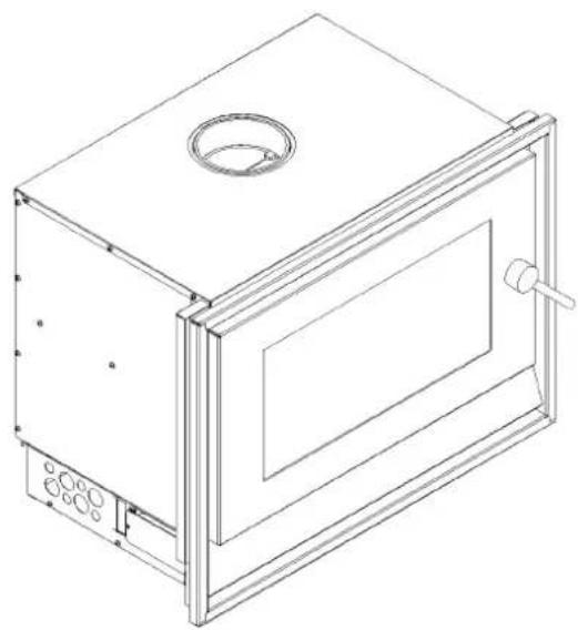
Technical line drawing of a rectangular industrial furnace or oven unit with a circular vent and side panel (no text or symbols)B520
B820
Keep instructions for future reference

AUSTRALIAN HOME HEATING ASSOCIATION INC.

Glen Dimplex Australia proudly supports the activities of Landcare Australia through its membership of the AHHA
CONTENTS
1. INSTALLATION .... 1
1.1. IMPORTANT INFORMATION .... 1
1.2. MASONRY INSTALLATION....2
1.3. ZERO CLEARANCE INSTALLATION....4
1.4. INSTALLING THE BAFFLE PLATE 7
1.5. INSTALLING THE FIRE BRICKS 7
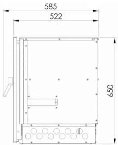
1.6. TECHNICAL DRAWINGS 8
1. INSTALLATION
THE INSTALLATION INSTRUCTIONS IN THIS MANUAL APPLY TO THE BLAZE B520 AND B820 INSERT WOOD HEATER MODELS.
THEY HAVE BEEN TESTED FOR EMISSIONS AND EFFICIENCY AND COMPLY ACCORDING TO AS/NZS 4012:2014 & AS/NZS 4013:2014.
1.1. IMPORTANT INFORMATION
The unit must be installed according to all manufacturers' instructions included in this manual. The manufacturer is not liable for installations that do not meet the requirements outlined in this manual.
Most building regulatory authorities in Australia require any wood heater installation to comply with Installation Standard AS/NZS 2918. Different states and councils may have varying regulations. Check local building regulations before installing the appliance.
All Blaze wood heaters have been tested to ensure they will meet the appropriate safety standard requirements if the instructions in this manual are followed. As the safety and emissions performance can be affected by altering the appliance, no modifications are allowed without written permission from the manufacturer.
WE RECOMMEND THAT THE INSTALLATION OF YOUR BLAZE WOOD HEATER BE CARRIED OUT BY A QUALIFIED INSTALLER.
WARNING: THE APPLIANCE AND FLUE SYSTEM SHALL BE INSTALLED IN ACCORDANCE WITH AS/NZS 2918 AND THE APPROPRIATE REQUIREMENTS OF THE RELEVANT BUILDING CODE OR CODES.
WARNING: APPLIANCES INSTALLED IN ACCORDANCE WITH THIS STANDARD SHALL COMPLY WITH THE REQUIREMENTS OF AS/NZS 4012 & AS/NZS 4013 WHERE REQUIRED BY THE REGULATORY AUTHORITY, I.E. THE APPLIANCE SHALL BE IDENTIFIABLE BY A COMPLIANCE PLATE WITH THE MARKING 'TESTED TO AS/NZS 4012 & AS/NZS 4013'.
ANY MODIFICATION OF THE APPLIANCE THAT HAS NOT BEEN APPROVED IN WRITING BY THE TESTING AUTHORITY IS CONSIDERED TO BE IN BREACH OF THE APPROVAL GRANTED FOR COMPLIANCE WITH AS/NZS 4012 & AS/NZS 4013.
CAUTION: MIXING OF APPLIANCE OR FLUE-SYSTEM COMPONENTS FROM DIFFERENT SOURCES OR MODIFYING THE DIMENSIONAL SPECIFICATION OF COMPONENTS MAY RESULT IN HAZARDOUS CONDITIONS. WHERE SUCH ACTION IS CONSIDERED, THE MANUFACTURER SHOULD BE CONSULTED IN THE FIRST INSTANCE.
CAUTION: CRACKED AND BROKEN COMPONENTS, EG. GLASS PANELS OR CERAMIC TILES, MAY RENDER THE INSTALLATION UNSAFE.
1.2. MASONRY INSTALLATION
Refer to this section for clearance requirements and instructions if the heater is to be in a masonry installation.
Clearances to Combustible Materials
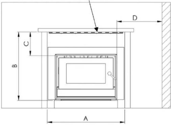
The dimensions given in the table and image below represent the minimum clearance (in millimetres) to combustible materials, such as a mantelpiece with columns, when installed in a non-combustible fireplace. If a combustible mantelpiece is present, a Mantelpiece Shield must be installed (refer to section 'Mantelpiece Shield').
| B520 | B820 | |
| A (Width between mantelpiece columns) | 900 | 1020 |
| B (Height to mantelpiece from hearth) | 970 | 1080 |
| C (Height to mantelpiece above air vents) | 400 | 450 |
| D (Distance to side wall from side of facia) | 200 | 250 |
Mantelpiece Shield
Floor Protector (Hearth)
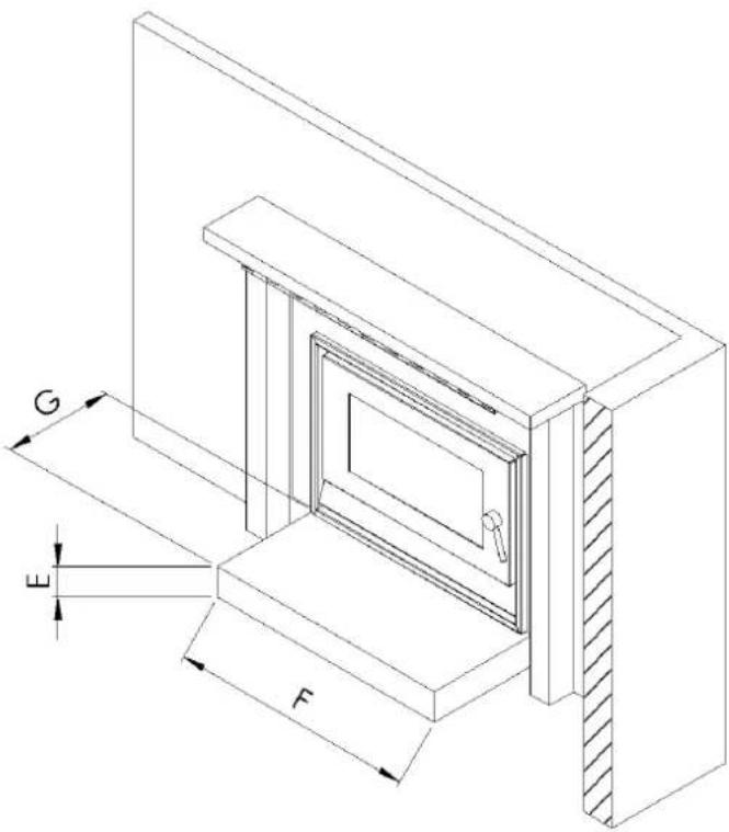
The dimensions given in the table and image below represent the minimum hearth sizes (in millimetres), when installed in a non-combustible fireplace, with either cement sheet (thermal conductivity not greater than 0.33W/m ^9 K) or brick.
- The dimensions can be larger than the minimum dimensions given here if desired.
- The floor protector may be laid directly on the combustible floor.
- For more details and variations on floor protectors refer to AS/NZS 2918 Clause 2.2, 3.3.1, & 3.3.2.
| B520 | B820 | |||
| Hearth Material (or equivalent) | Cement sheet | Brick | Cement sheet | Brick |
| E (Thickness) | 15 | 110 | 15 | 110 |
| F (Width) | 900 | 900 | 1000 | 1000 |
| G (Depth from door) | 400 | 300 | 500 | 300 |
For variations to clearances relative to a combustible mantelpiece refer to AS/NZS 2918 Clause 3.4.2.
Mantelpiece Shield
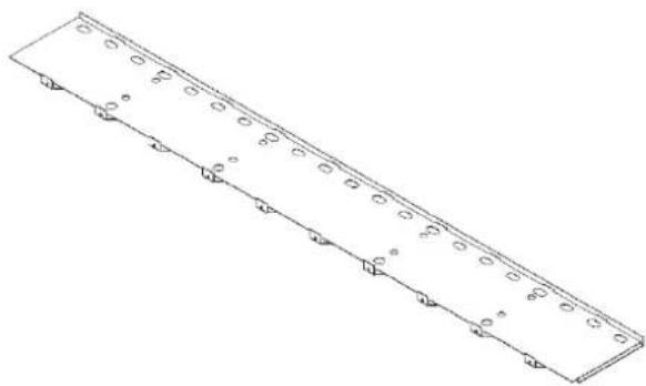
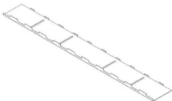
If the installation contains a mantelpiece made of combustible material, the Mantelpiece Shield (which needs to be ordered separately) must be fitted.
Parts Supplied:
1x Upper Shield
natural_image
Isometric line drawing of a rectangular structure with evenly spaced circular elements, no text or symbols present.1x Lower Shield
natural_image
Isometric line drawing of a rectangular structure with internal stepped divisions (no text or symbols)4x M6 Screws
4x M6 Washers
8x 8# Wood Screws
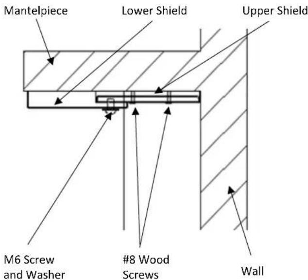
The Mantelpiece Shield can extend to fit a mantelpiece with a depth greater than 140mm, following these steps:
1) If required, trim width of shield to suit width of mantelpiece. Material may have to be removed from both ends to be symmetrical.
2) Hold upper shield hard against the wall and underside of mantelpiece. Screw in place with #8 wood screws.
3) Attach lower shield to upper shield with M6 screws and washers loosely.
4) Slide lower shield until the front is 2mm inside from the edge of the mantelpiece. If the mantelpiece depth is greater than the reach of the shield, slide to fully extended position.
5) Tighten M6 screws until held firm, but not so tight that the shield buckles.
Flue
In a masonry installation, a 150mm diameter flue must extend through the chimney, from firebox to atmosphere.
Fitting Flue Seal
Any gaps between the inside of the flue spigot and the 6 inch active flue should be sealed. This can be done by wrapping the bottom of the flue with the piece of adhesive backed high temperature cloth tape supplied. Alternatively, stove cement designed for this purpose can also be used.
1.3. ZERO CLEARANCE INSTALLATION
Refer to this section for clearance requirements and instructions if the heater is to be in a zero clearance installation.
A licensed accredited installer should install all wood heaters. Please ask your retailer to locate an installer.
All warranty is void unless installed by an authorised installer.
Parts Supplied
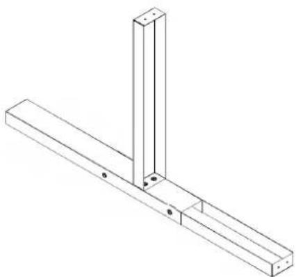
The zero clearance kit (supplied separately) includes these parts:
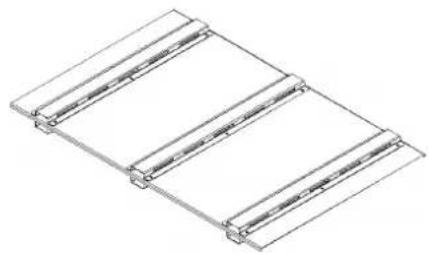
1x Zero clearance base
natural_image
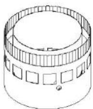
Isometric line drawing of a structural frame with three vertical supports (no text or symbols)1x Vented outer casing
natural_image
Isometric line drawing of a cylindrical mechanical component with internal slots and a small hole (no text or symbols)1x Enclosure channel vertical
2x Enclosure channel horizontal
4x Wafer head screws #10x16mm
6x Wafer head timber screws #10x45mm
natural_image
Isometric line drawing of a structural beam with two vertical supports and mounting holes (no text or symbols)Clearances to Combustible Materials
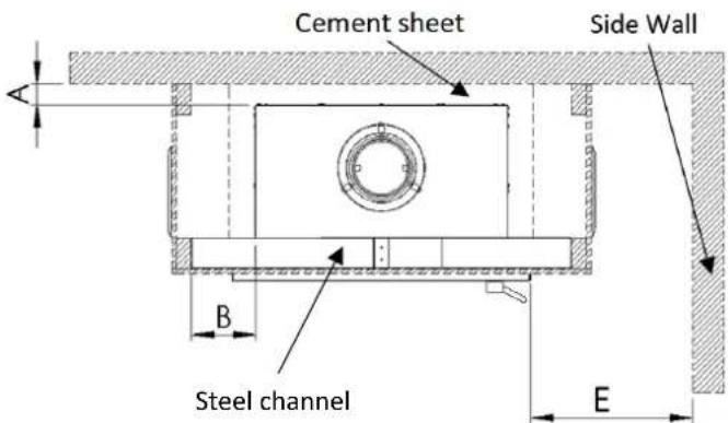
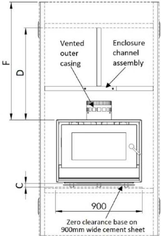
The table below gives minimum clearances (in mm) from the appliance to combustible materials. All dimensions are from the surfaces on the outer box of the appliance (see diagram in in following section Enclosure Construction). Internal clearances are within the enclosure, and external clearances are outside the enclosure (inside the area to be heated).
| B520 | B820 | |
| A (Rear Internal) | 40 | 40 |
| B (Side Internal) | 150 | 150 |
| C (Height of zero clearance base) | 40 | 40 |
| D (Above Internal) | 500 | 500 |
| E (Side Wall External) | 200 | 250 |
| F (Ceiling External) | 1260 | 1200 |
Enclosure Construction (with minimum clearances)
The following drawings show the construction of an enclosure with minimum clearances to combustible materials from the appliance determined in accordance with AS/NZS 2918.
These are minimum clearances and may be installed with greater clearances if desired.
- The frame is constructed of 90x45mm timber, displayed as dashed lines.
- The appliance and zero clearance base sits on a 5(H) x 900(W) x 545(D)mm cement sheet.
- The supplied enclosure channels are assembled and screwed onto the enclosure above the appliance.
- The cladding on the front wall must be a non-combustible material such as cement sheeting.
Note: Additional supports should be used to support the weight of the heater, zero clearance base and flue system. These have not been shown in the drawing.
Enclosure Ventilation
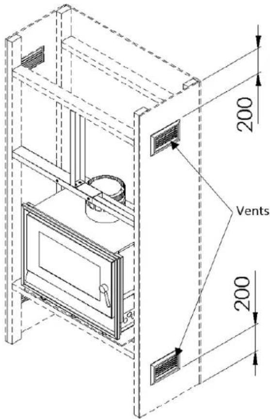
The enclosure must be ventilated. Vents with a minimum free area of 7350mm^2 must be fitted on both sides, not more than 200mm above the floor.
B820 must have be fitted with vents at the top as well.
Similar size vents with a minimum free area of 7350mm^2 must be fitted on both sides not lower than 200mm below the ceiling.
The purpose of the vents is to allow cooler air to be drawn into the enclosure through the bottom vent, and warm air out through the top vent via natural convection back into the room.
Floor Protector (Hearth)
The zero clearance base must be supported on a layer of cement sheet with a minimum thickness of 5mm, measuring 900mm wide x 500mm deep. Any wider, and it will restrict the ventilation from the lower vents past the appliance.
The minimum dimensions of the floor protector are dependent on the height above the floor at which the heater is installed.
250mm or more above floor:
| B520 | B820 | |
| Thickness | 7.5 | 7.5 |
| Width | 900 | 1000 |
| Depth from door | 300 | 300 |
Less than 250mm above floor:
| B520 | B820 | |||
| Hearth Material (or equivalent) | Cement sheet | Brick | Cement sheet | Brick |
| Thickness | 15 | 110 | 15 | 110 |
| Width | 900 | 900 | 1000 | 1000 |
| Depth from door | 400 | 300 | 500 | 300 |
(These are the same as for a masonry installation).
Flue
Install a 150mm diameter double cased flue kit to comply with AS 2918. The double casing must extend from the vented outer casing on top of the appliance, all the way through to the top where the flue terminates. A hole of 300 mm diameter is required in the ceiling with a minimum 25 mm clearance between any combustible material and the 250mm outer casing.
Fitting Flue Seal
Any gaps between the inside of the flue spigot and the 6 inch active flue should be sealed. This can be done by wrapping the bottom of the flue with the piece of adhesive backed high temperature cloth tape supplied. Alternatively, stove cement designed for this purpose can also be used.
Power Supply for Fan
Provide a power point in the cavity under the heater for connecting the fan in the heater. If the cavity under the heater will not be accessible once the heater is installed (such as through a removable vent) then ensure an extension cord long enough to reach out of the front of the opening is lying in the base of the cavity.
When connecting the lead from the fan to the extension cord, it is suggested to tape the connection together. This is to prevent separation if the remote receiver requires removal and the lead must be pulled through.
Facia Options
A 4mm thick facia can be installed on the unit (supplied separately). Four facia options are available for each model (B520 or B820).
- Facia 4 Sided 50mm (50mm visible edges)
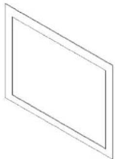
natural_image
Simple line drawing of a rectangular frame with no text or symbols- Facia 4 Sided 100mm (100mm visible edges)
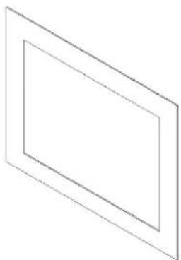
natural_image
Simple line drawing of two overlapping rectangular frames (no text or symbols)- Facia 3 Sided 50mm (50mm visible edges)
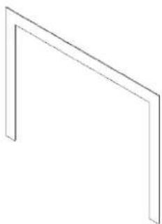
natural_image
Simple line drawing of a U-shaped frame (no text or symbols)- Facia 3 Sided 100mm (100mm visible edges)
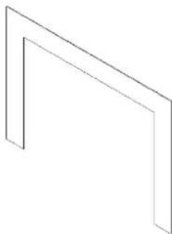
natural_image
Simple line drawing of a 3D rectangular frame with no text or symbols1.4. INSTALLING THE BAFFLE PLATE
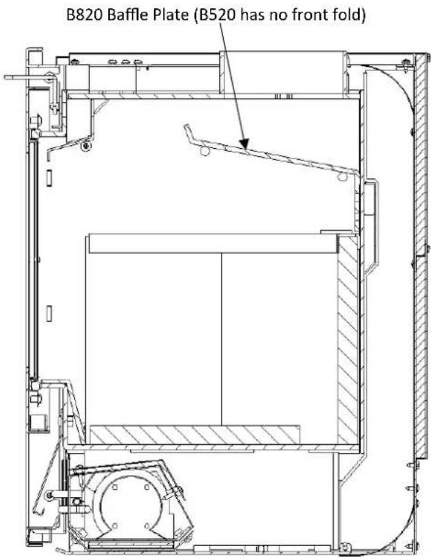
The baffle plate should be installed before installing the fire bricks.
1) Place the baffle plate inside the firebox with the back fold (with slots) pointing towards the bottom rear corner.
2) Raise the front of the baffle and place it above the front pins from behind.
3) Raise the rear of the baffle and place it over the rear pins (see image below for correct baffle placement).
1.5. INSTALLING THE FIRE BRICKS
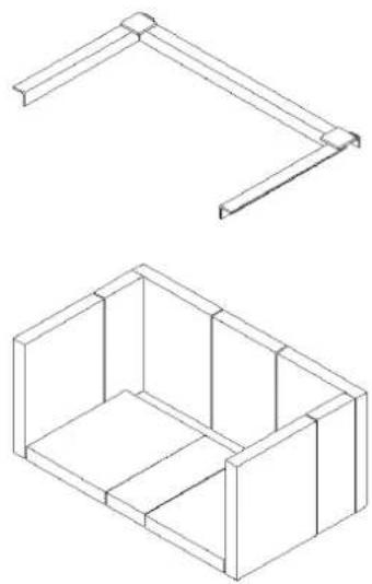
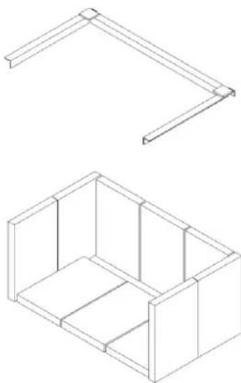
Place the bricks into the firebox as shown in the diagrams below for the B520 and B820.
Once bricks are in, fit the retainer over the top to hold them in place.
B520
- Two full size (220 x 175 x 25) and one (220 x 140 x 25) along the back.
- One full size and one half size (220 x 85 x 25) along each side.
- Two full size and one half size in the base.
natural_image
Two technical line drawings of a mechanical frame structure, top shows L-shaped supports and bottom shows a rectangular housing (no text or symbols)B820
- Three full size (270 x 175 x 25) along the back.
- Two full size along each side.
• Three full size in the base.
natural_image
Technical line drawing of two 3D structural components: a frame-like L-shaped bracket and a rectangular box with internal compartments (no text or symbols)1.6. TECHNICAL DRAWINGS
B520
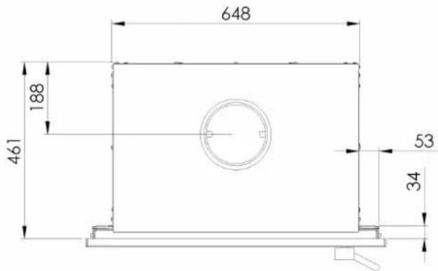
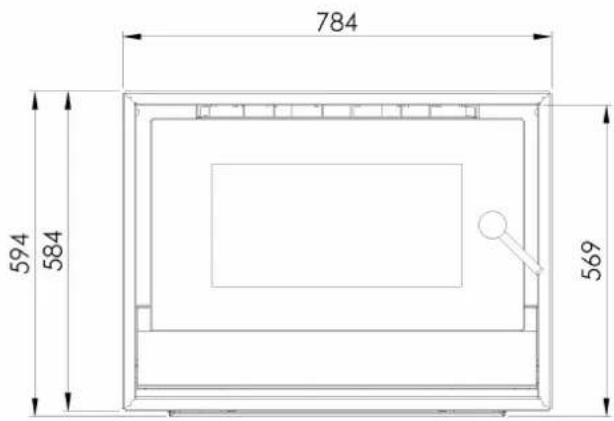
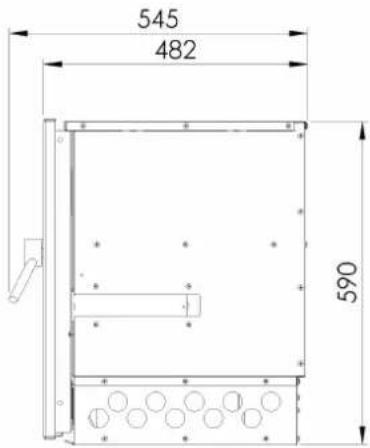
B820
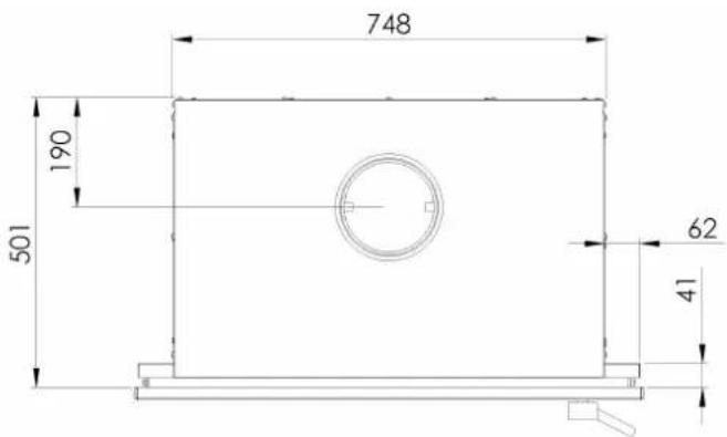
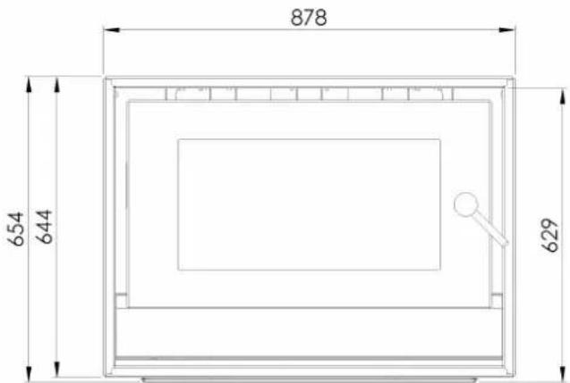
Glen Dimplex AUSTRALIA
Glen Dimplex Australia Pty Ltd
8 Lakeview Drive, Scoresby Victoria 3179 Australia
T: 1300 556 816 | F: 1800 058 900
Email: sales@glendimplex.com.au
- Installation Instructions
- CONTENTS
- INSTALLATION .... 1
- INSTALLATION
- IMPORTANT INFORMATION
- MASONRY INSTALLATION
- Clearances to Combustible Materials
- Floor Protector (Hearth)
- Mantelpiece Shield
- Flue
- Fitting Flue Seal
- ZERO CLEARANCE INSTALLATION
- Parts Supplied
- Enclosure Construction (with minimum clearances)
- Enclosure Ventilation
- B820 must have be fitted with vents at the top as well.
- Power Supply for Fan
- Facia Options
- INSTALLING THE BAFFLE PLATE
- INSTALLING THE FIRE BRICKS
- B520
- B820
- TECHNICAL DRAWINGS
- Glen Dimplex AUSTRALIA
Brand : Blaze
Model : B820
Category : Heating