
MXRT-4700 - Monitor Barco - Free user manual and instructions
Find the device manual for free MXRT-4700 Barco in PDF.


| Product Type | Medical Grayscale Monitor |
| Brand | Barco |
| Model | MXRT-4700 |
| Display Size | 21.3 inches (diagonal) |
| Resolution | 2048 x 2560 pixels (5MP) |
| Pixel Pitch | 0.165 mm |
| Brightness | 1100 cd/m² (typical) |
| Contrast Ratio | 1400:1 |
| Viewing Angles | 176° horizontal / 176° vertical |
| Gray Levels | 10-bit (1024 shades) |
| Backlight | LED |
| Inputs | 2x DVI-D, 1x DisplayPort |
| Power Supply | 100–240 VAC, 50/60 Hz |
| Power Consumption | 70 W (typical) |
| Dimensions (W x H x D) | 476 x 488 x 99 mm (without stand) |
| Weight | 9.5 kg (without stand) |
| Mounting | VESA 100 mm x 100 mm |
| Operating Temperature | 0°C to 40°C |
| Calibration | DICOM-compliant, external sensor supported |
| Certifications | CE, FDA, CCC, UL |
| Warranty | 3 years (standard) |
Frequently Asked Questions - MXRT-4700 Barco
User questions about MXRT-4700 Barco
0 question about this device. Answer the ones you know or ask your own.
Ask a new question about this device
Download the instructions for your Monitor in PDF format for free! Find your manual MXRT-4700 - Barco and take your electronic device back in hand. On this page are published all the documents necessary for the use of your device. MXRT-4700 by Barco.
USER MANUAL MXRT-4700 Barco
Display Controller and Intuitive Workflow Tools
natural_image
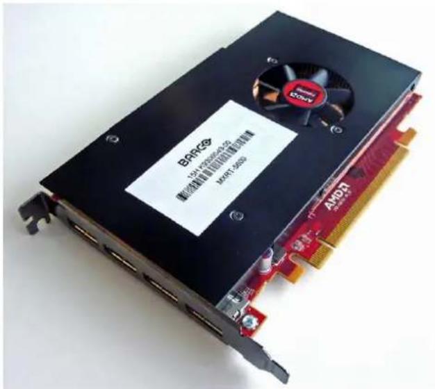
Close-up of a black BARRC processor with an AMD card and fan, no visible text or symbols on the main components.User Guide
Windows 7 and Windows 10
Barco NV
Beneluxpark 21, 8500 Kortrijk, Belgium
www.barco.com/en/support
www.barco.com
Registered office: Barco NV
President Kennedypark 35, 8500 Kortrijk, Belgium
www.barco.com/en/support
www.barco.com
Table of contents
1 Welcome! 7
1.1 About the product....8
1.2 What's in the box....8
2 Display Controller installation 9
2.1 Which Display Controller? 10
2.2 Installing a Barco Display Controller 10
2.3 Installation procedure 10
2.4 Connecting your Barco Displays 11
2.5 Dongles 12
2.5.1 Passive Single-Link Dongle 12
2.5.2 Active Single-Link Dongle 13
2.5.3 Active Dual-Link Dongle 13
2.6 Shipping the Barco Display Controller 13
3 Driver and software installation....15
3.1 Introduction....16
3.2 Installation procedure 16
3.3 Silent installation 17
3.4 Installation options....18
3.5 After installation 18
3.6 Uninstallation....19
4 Configuring Barco displays in Windows 21
4.1 Display resolution 22
4.2 Software rotation 22
4.3 Night light 23
5 Driver and Intuitive Workflow Tools 25
5.1 Barco System Settings Control Panel 26
5.1.1 Description....26
5.1.2 Operation 27
5.1.3 Version information of the Intuitive Workflow Tools 28
5.1.4 Compatibility of the Intuitive Workflow Tools 28
5.2 Application Appearance Manager 28
5.2.1 Description 28
5.2.2 Operation 29
5.2.3 Configuration 29
5.3 Color and Grayscale Depth 29
5.3.1 Description....29
5.3.2 Operation....30
5.3.3 Configuration 30
5.4 Conference CloneView™ 30
5.4.1 Description....30
5.4.2 Operation....30
5.4.3 Configuration 31
5.5 DimView™ 31
5.5.1 Description....31
5.5.2 Operation....32
5.5.3 Configuration 32
5.6 Film Clip 32
5.6.1 Description....32
5.6.2 Operation....32
5.6.3 Configuration 32
5.7 FindCursor™ 33
5.7.1 Description....33
5.7.2 Operation....33
5.7.3 Configuration 33
5.8 I-Luminate™ 33
5.8.1 Description....33
5.8.2 Operation....34
5.8.3 Configuration 34
5.9 Reading Environment....34
5.9.1 Description....34
5.9.2 Operation....34
5.9.3 Configuration 35
5.10 Screen Capture 35
5.10.1 Description....35
5.10.2 Operation 35
5.10.3 Configuration 36
5.11 SingleView™ 36
5.11.1 Description....36
5.11.2 Operation 36
5.11.3 Configuration 36
5.12 SmartCursor™ 36
5.12.1 Description....36
5.12.2 Operation 37
5.12.3 Configuration 37
5.13 SoftGlow™ 37
5.13.1 Description....37
5.13.2 Operation 38
5.13.3 Configuration 38
5.14 SpotView™ 38
5.14.1 Description....38
5.14.2 Operation 38
5.14.3 Configuration 39
5.15 Touchpad gestures....40
5.15.1 Description....40
5.15.2 Operation 40
5.15.3 Configuration 41
5.16 VirtualView™ 41
5.16.1 Description....41
5.16.2 Operation....42
5.16.3 Configuration 42
6 Important information....43
6.1 Safety information....44
6.2 Environmental information 44
6.3 Regulatory compliance information 46
6.3.1 Display Controllers 46
6.3.2 Intuitive Workflow Tools 46
6.4 Explanation of symbols....47
6.5 Legal disclaimer 49
6.6 Technical specifications....50
Welcome!
1
1.1 About the product
Overview
Thank you for choosing this Barco Display Controller!
Barco's state-of-the-art Display Controllers deliver the performance, quality and stability required for today's advanced medical imaging applications. The powerful boards ensure ultra-fast and smooth image loading, and graphics processing of images in every resolution. Use the instructions in this guide to install your B Display Controller.
The Barco MXRT Software Package includes the driver for the Barco Display Controller and the Barco Intuitive Workflow Tools. The instructions in this guide show how to download and install the Barco MXRT Software Package and how to use the Intuitive Workflow Tools.
1.2 What's in the box
Contents
Your Barco Display Controller comes with:
• This Barco Display Controller User Guide
• 1 extender bracket is included with the MXRT-7600 & MXRT-8700.
• 1 low-profile bracket is included with the MXRT-2600, MXRT-2700, & MXRT-4700.
• 2 mini-DisplayPort-to-DisplayPort adapters are included with the MXRT-2700 & MXRT-4700.
• 4 mini-DisplayPort-to-DisplayPort adapters are included with the MXRT-8700.

Keep your original packaging. It is designed for this Display Controller and is the ideal protection during transport and storage.
Display Controller installation
2
2.1 Which Display Controller ?
Display Controller range
Your Barco medical display is compatible with a large range of Barco Display Controller boards. Depending the order details, the display can be delivered with or without a Display Controller.
If you are installing a Barco Display Controller, please follow the installation instructions in this section.
Barco displays are compatible with a limited set of non-Barco display controllers. If you are installing a n Barco display controller, please consult its corresponding documentation.
2.2 Installing a Barco Display Controller
Guidance
This chapter will guide you through the physical installation of a Barco Display Controller for your display system.

WARNING: Installation should only be performed by trained technical personnel.

WARNING: Wear a grounded, protective ESD strap when handling or during installation of the Display Controller. Electrostatic charges can damage the Display Controller.
Overview
Prior to installing the Barco Display Controller(s) for your Barco Display System in your workstation, please take a few minutes to familiarize yourself with the Display Controller(s) and the PCIe slots.
Which PCIe slot to use
Each Barco Display Controller model should be deployed in a PCIe X16 Gen3 slot. The image below shows PCIe X16 slot.

Image 2-1 PCIe X16 slot
2.3 Installation procedure

If you are using a motherboard containing an on-board graphics solution and do not intend to us as part of a multiple-display setup, disable it either in the computer's System Set-up utility (BIOS) or the Windows device manager.
How to install
The following instructions will take you step by step through the installation of the Barco Display Control for your Barco Display System.
- If you are not going to use your old Display Controller, uninstall its drivers and software.
- Turn off the computer, display(s), and other peripheral devices.
- Unplug the computer's power cord and disconnect all cables from the back of your computer.
Warning: Wait approximately 20 seconds after unplugging the power cord before disconnecting a peripheral or removing a component from the motherboard to avoid possible damage to the motherboard.
-
Remove the computer cover. If necessary, consult your computer's manual for instructions.
-
If necessary, unscrew or unfasten and remove any existing display controller(s) from your computer.
-
Locate the appropriate slot and, if necessary, remove the metal back-plate cover(s).
-
Align the Barco Display Controller(s) for your Barco Display System with the slot(s) and press it(them) in firmly until the card(s) is(are) fully seated.
-
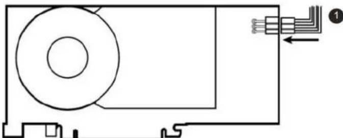
Connect the power cable, available from the workstation vendor, to the 6-pin power connection on the Display Controller. Make sure the cables are not interfering with anything inside the computer (for example, a coo fan).

Tip: This step only applies to the MXRT-7600 & MXRT-8700.
natural_image
Pure technical line drawing of a mechanical component with no text or symbolsImage 2-2 Power connection for the MXRT-7600 & MXRT-8700 controllers
- Screw in or firmly fasten the Display Controller. Replace and secure the computer cover.
2.4 Connecting your Barco Displays

For a detailed description of the display installation and signal connection, please refer to the Display User Guide.
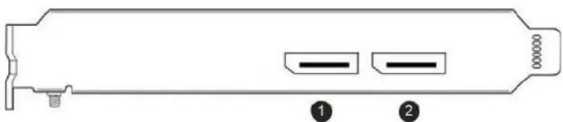
IO-Panel for the Barco MXRT-2600
natural_image
Technical line drawing of a device casing with two labeled components (no text or symbols present)Image 2-3 MXRT-2600
- DisplayPort #1
- DisplayPort #2
IO-Panel for the Barco MXRT-5600, MXRT-6700 & MXRT-7600
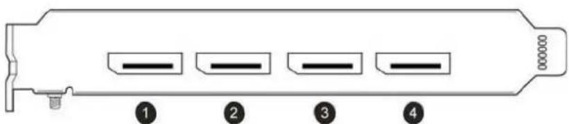
Image 2-4 MXRT-5600, MXRT-6700, MXRT-7500 & MXRT-7600
- DisplayPort #1
- DisplayPort #2
- DisplayPort #3
- DisplayPort #4
IO-Panel for the Barco MXRT-2700 & MXRT-4700
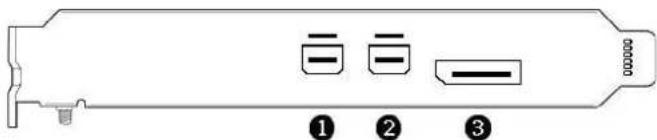
Image 2-5 MXRT-2700 & MXRT-4700
- Mini DisplayPort #1
- Mini DisplayPort #2
- DisplayPort #1
IO-Panel for the Barco MXRT-8700
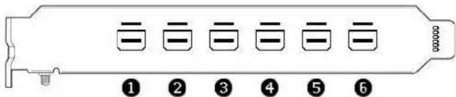
Image 2-6 MXRT-8700
- Mini DisplayPort #1
- Mini DisplayPort #2
- Mini DisplayPort #3
- Mini DisplayPort #4
- Mini DisplayPort #5
- Mini DisplayPort #6
2.5 Dongles
About
Barco dongles are designed to allow Barco Display Controllers with a DisplayPort connector to a display, only a DVI input. All current Barco displays support direct DisplayPort connection.

If video cable conversion is not required, you may bypass this section.
Barco dongles are available for purchase independently.
2.5.1 Passive Single-Link Dongle
About
The passive Single-Link Dongle converts DisplayPort input signals to single-link DVI output signals. It is compatible with all Barco grayscale displays and up to 2MP color models. For color displays of 3MP and greater resolutions, the Dual-Link Dongle is necessary.

natural_image
Close-up of a white DVI connector with a black USB cable, labeled with numbers 1 and 2 (no text or symbols on the connector itself)Image 2-7 Single-Link dongle
- To display Single-Link DVI cable
- To DisplayPort connector on Barco Display Controller
2.5.2 Active Single-Link Dongle
About
Barco Display Controllers are not compatible with third-party active single-link dongles. Please use Barco passive Single-Link dongles.
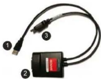
2.5.3 Active Dual-Link Dongle
About
The active Dual-Link Dongle converts DisplayPort input signals to dual-link DVI output signals. Unlike the passive Single-Link dongle, the Dual-Link dongle allows higher resolutions (greater than 1920x1200) on colo displays.

When using QAWeb software for calibration and quality assurance of a display connected through Dual-Link dongle, a USB cable must also be connected to the display.
natural_image
Close-up of a USB cable with two connectors and a black connector (no visible text or symbols)Image 2-8 Dual-Link dongle
- To computer's USB port
- To display via DVI Dual-Link cable
- To DisplayPort connector on Barco Display Controller
2.6 Shipping the Barco Display Controller
About
After the installation and validation of software components, Barco recommends removing the display controllers from the workstation and returning them to their original packaging prior to shipment.

Barco does not recommend shipping display controllers installed in the workstation.
If it is necessary to ship a controller installed in a workstation, the MXRT-7600 and MXRT-8700 require an extender bracket to protect against shock and vibration. Assemble the extender bracket as shown below. Refer to the workstation user documentation on proper installation to its card guide.
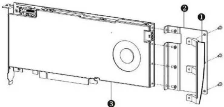
Image 2-9 MXRT-7600 & MXRT-8700 Extender Bracket
-
Bracket
-
Extender
- MXRT-7600 & MXRT-8700
Driver and software installation
3
3.1 Introduction
About
This chapter will guide you through the installation of the drivers, software and documentation associated with your Barco Display System or Barco Display Controller(s).
Prerequisites
Before starting the installation of the Barco drivers, software and documentation following prerequisites must be adhered:
- Your operating system must be installed and running. Windows 7 (64-bit) and Windows 10 (64-bit) are supported.
- You must be logged on as a user with local administrator privileges.
- All Barco displays must be connected to the appropriate Display Controller(s) in your system.

For optimal system performance, Barco recommends installing no more than two drivers on a system at one time. If the configuration will require three drivers, the Barco Driver Installer will all the user to replace one board to eliminate one of the drivers.
- When there is a non-Barco board in the system, you must first install the driver for the non-Barco display controller before installing the Barco driver.

After each driver installation, you should reboot the system before proceeding with the installation another driver.
You will need to install the Barco Display Controller system drivers and software in the following cases:
- After you have installed the Barco Display Controller(s) for your Barco Display System in your system for the first time.
• After you have reinstalled or upgraded your operating system. - When upgrading to a newer version of the MXRT driver and software, manual uninstallation of the prior version is not necessary. The Barco Product Installation Wizard will detect any prior installations and st the uninstallation process automatically.

The installation dialog will display in English if your operating system's language is not supported.
3.2 Installation procedure
Installation procedure
- Start your system.
If you have a fresh OS installation, or you have uninstalled an existing driver, the OS may automatically an inbox driver from the Windows driver store, either an AMD driver or a standard VGA driver, for the I Display Controller(s). If this occurs, the OS prompts you to restart your computer, click Yes to allow the automatic driver installation to complete and reboot the system.
-
Download the installer from the Barco public site for your controller, such as https://www.barco.com/en/product/mxrt-5600. Launch the Barco Product Installation Wizard by clicking master_setup.exe in the Barco folder.
-
The first page of the installation wizard is the license agreement. You must accept the license agreement in order to proceed.
-
The second page of the installation wizard will show you the display controller driver and software components that will be installed. To accept the installation of default software components, click Next. To custom select software components, click on specific software components to unselect them.
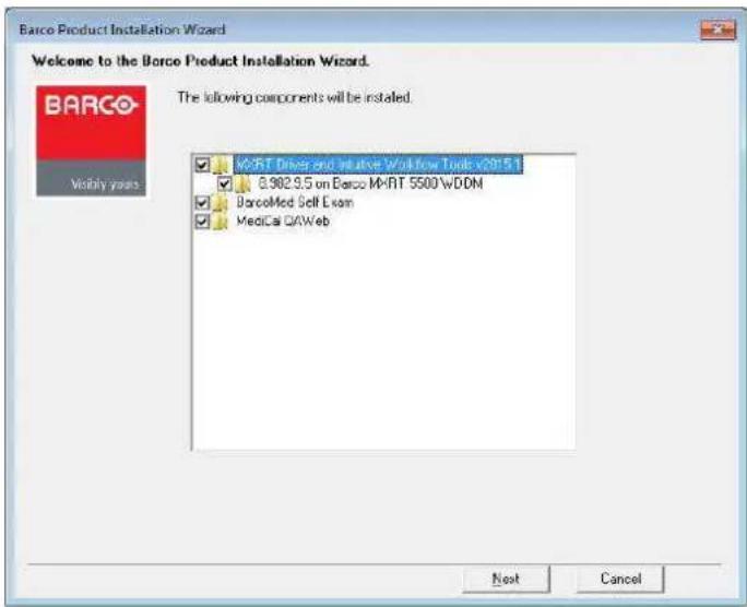
Image 3-1 Barco Product Installation Wizard
• MXRT Driver and Intuitive Workflow Tools: Barco MXRT Display Controller drivers and accompanying software for supporting Intuitive Workflow Tools
• BarcoMed Self Exam: Barco diagnostic tool
• MediCal QAWeb Agent: Barco calibration software
-
If a previous installation of an MXRT driver exists, the installation wizard will detect it and guide you through the uninstallation process if necessary.
-
During installation, the desktop may flash, and the Installation Wizard window may appear on different displays. This is expected behavior.
-
When the installation of all components has completed, the system must reboot to complete the changes, and an automatic reboot window will be displayed.
3.3 Silent installation
Installation procedure
Navigate to the Barco installation folder and execute the command master setup.exe -silent.
This can be done from the command shell, from the Run command, or from a command shortcut. The s program will automatically install the drivers for any MXRT boards that are present, the BarcoMed Self Ex program, and QAWeb (if part of the installation package).
Configure silent installation options
You can modify the setup. ini file at the Barco root folder to customize certain silent install behavior. The configurable options are listed in the [Custom] section of the setup.ini file.
Reboot
- Locate the [Custom] section of setup.ini.
- If set to Yes (default), the installer will prompt the user or launch a timer to reboot following software installation. If No, the prompt/timer is not shown.
3.4 Installation options
Configure installation options
You can modify the setup. ini file at the Barco root folder to change the default setting of MXRT driver either installation or silent installation.
Install driver in 24-bit
- Locate the [MXRT_WDDM] section of setup.ini
- Remove -30bit command line parameter from both Install and SilentInstall lines
- Modify the default.ini file, found in: Barco_MXRT_Driver_SoftwarePackage_xxxx\Setup_Barco_Productivity_Tools.x.x.x\Change Color%20Depth\30BitDesktop to false.
Install driver with Coronis Fusion displays in SingleView mode
- Locate the [MXRT_WDDM] section of setup.ini
- Add -singleview command line parameter to the end of both Install and SilentInstall lines
- Modify the default.ini file, found in: Barco_MXRT_Driver_SoftwarePackage_xxxx\Setup_Barco_Productivity_Tools.x.x.x\ Change SingleView\singleviewEnabled to true.
Install driver with VirtualView enabled
- Locate the [MXRT_WDDM] section of setup.ini
- Add -virtualview parameter to both Install and SilentInstall lines
- Modify the default.ini file, found in: Barco_MXRT_Driver_SoftwarePackage_xxxx\Setup_Barco_Productivity_Tools.x.x.x\Change VirtualView\FeatureEnabled to true.
3.5 After installation
Installation verification
To verify that the driver was installed, go to the Windows Control Panel, select System, select Device Manager, then select Display Adapters. Verify that Barco Display Controllers are properly identified, as shown below:
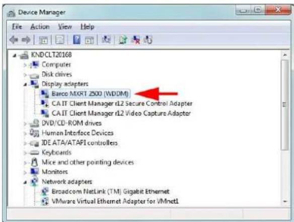
Image 3-2 Verifying driver installation
Automatic display configuration
Once the drivers, software and documentation have been installed and the system has been rebooted, the computer should automatically detect your Barco displays and attach them to the desktop with the correct resolution. If the computer fails to detect your Barco displays or fails to attach them to the desktop correct please use the Windows Screen Resolution to set the correct resolution.
Upgrade drivers
When performing a driver upgrade, the Barco System Settings Control Panel default profile will be applied. Any user profile that was saved on the system previously is still available and can be selected through 1 Barco System Settings Control Panel.
3.6 Uninstallation
Uninstalling the drivers and software
To uninstall the Barco drivers, software or documentation for your Barco Display System, please use the Windows Add/Remove Programs. This can be found in the Windows Control Panel under Programs & Features.
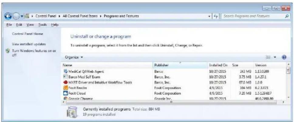
Image 3-3 Windows 7 Add/Remove Programs
Barco System Cleaner
The Barco System Cleaner is a tool that will remove all Barco software components from your workstation. This includes the display driver, the accompanying software for supporting Intuitive Workflow features, BMSE and QAWeb calibration software. The application can be found at C:\Program Files\Barco.

The Barco System Cleaner will remove all Barco components from your system. It is recommend only use the System Cleaner under direction of Barco Customer Support.
Configuring Barco displays in Windows
4
4.1 Display resolution
Changing resolutions
-
Click on the Configure Displays button on the Barco System Settings Control Panel or right click on the desktop and select Screen resolution in Windows 7 and 8.1. This will open the Windows Control Panel shown in Image 4-1. In Windows 10, right click on the desktop and select Display settings to launch a control panel with similar functions but a different look and feel.
-
Click on the Resolution drop down box to show the list of resolutions.
-
Select the desired resolution, and click Apply.
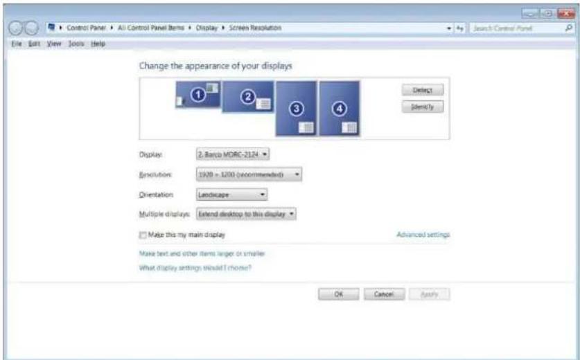
Image 4-1 Windows Display Control Panel

In Windows 7, the maximum horizontal resolution of the desktop is 8192 pixels for a single displ controller. Your calculation should include the VirtualView display, if used. Please refer to Microsoft Knowledge Base article 2724530.
4.2 Software rotation
Configuring screen orientation
Software rotation is only necessary for displays that do not support hardware rotation, such as MDRC dis and some third-party displays.
- Right click on the Desktop, and select Screen Resolution in the context menu.
- Select a Display.
-
In the Orientation drop down list, these options are available:
-
Landscape
- Portrait
- Landscape (flipped)
-
Portrait (flipped)
-
Select the desired setting, and click Apply.
4.3 Night light
Disabling Night light
Windows 10 provides a feature to shift the white point of light throughout the day. This is not recommer diagnostic workstations. It should be disabled by default. if Night light is enabled, follow these steps to di it:
- Right click on the Desktop, and select Display settings in the context menu.
- Under Night light, turn the feature to Off.
Driver and Intuitive Workflow Tools
5
5.1 Barco System Settings Control Panel
5.1.1 Description
Overview
The Barco System Settings Control Panel provides a centralized configuration interface for users to personalize their Barco Display System environment.
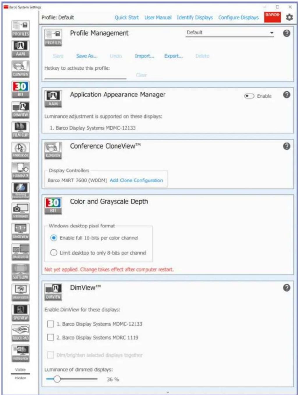
Image 5-1 Barco System Settings Control Panel
5.1.2 Operation
Accessing the Barco System Settings Control Panel
- Right click on the desktop and select Barco System Settings, or
- Click on the Barco icon in the System Tray, or
- Press the hotkey Control+ALT+O
Layout of the Barco System Settings Control Panel
The Barco System Settings Control Panel consists of 3 sections: the Control Bar at the top, the Navigation pane on the left, and the configuration tiles on the right. The Control Bar shows the current active profile provides 4 additional buttons.
- Open User Manual: This opens a PDF version of this user guide if a PDF viewer is installed in the system.
- Identify Displays: Some settings in the Barco System Settings Control Panel require selection of individual displays. Press this button to see which display corresponds to which configuration numbers.

The identification numbers used by the Barco System Settings Control Panel do not reflect the display ID number assigned by Windows as shown in the Windows Screen Resolution configuration page.
- Configure Displays: This opens the Windows Screen Resolution Control Panel to allow changes to the location and resolution of displays in the Windows desktop.
- Clicking the gear symbol opens the Control Panel Settings Box and allows the user to change set and view information of the Barco System Settings Control Panel.
- Hotkey to Show This Control Panel: Click Clear to remove the hotkey. Click on the hotkey box to enter a new one.
- Show Navigation Bar Popups: This button can enable popups on the Navigation Pane, making the icons larger and more legible.
- About Intuitive Workflow Tools: Click here to bring up the About box showing the product label with the version and regulatory information of the Intuitive Workflow Tools.
Through the Navigation Pane, the user can get quick access to the configuration tile of a feature by clicking its icon. The Navigation Pane also allows customization of the Barco System Settings Control Panel. Drag icons in the Navigation Pane will change the order of the tiles, allowing commonly used tiles to appear at top. In the middle of the Navigation Pane is the visibility line. The tile for any feature can be hidden by its corresponding Navigation Pane icon below the visibility line, reducing control panel clutter. If the icons are the Navigation Pane appear too small, popups with larger icons can be enabled in the Control Panel Set Box.
Each configuration tile contains controls for the given feature, and those controls are described later in this section. Each configuration tile contains a help icon and clicking on it will bring the user to the relevant section of this user guide.
Profile management
The Profile Management tile is an exception to the rules above; it cannot be reordered or hidden. Select options in the Barco System Settings Control Panel can be saved in profiles, and those profiles are manual with this tile. The profiles are specific to the current user, and they will be automatically applied when the logs into the system.
The profile can be exported to and imported from a remote disk, so it can be deployed to multiple systems
- Profile: The current profile is selected with this drop-down menu. If the profile is edited, it will be marked here as "modified".
- Save: This saves changes to the current profile. Changes to the Default profile cannot be saved.
- Save as...: This saves the current configuration setting as a profile with a new name. Provide a profile name in the popup dialog box.
- Undo: This reverts to the saved version of the current profile.
- Import...: This imports a profile from file and makes it available in the Profile list to be selected.
- Export...: This saves selected profiles on this system to a file. The selection is made from a dialog box.
- Delete: This removes the current profile from the profile list and restores the system to the Default profile.
To apply a profile system wide:
- Export the profile, and name it Default.ini
-
Edit the new file:
-
Change line 3 from names=
to names=Default -
Change line 5 from [<profileName] to [Default]
-
Replace the default profile in C:\Program Files\Barco\ProductivityTools\Default.ini with the new one.
5.1.3 Version information of the Intuitive Workflow Tools
Version(s) covered in this user guide
This user guide is compatible with all Core versions numbered 1.2.x.y and all Diagnostic versions numbered 2.0.x.y of the Intuitive Workflow Tools. Core versions of the Intuitive Workflow Tools do not contain those that are pending medical device clearance in some countries. The Diagnostic versions contain all tools with this guide. In these revision numbers, "x" refers to a software patch containing defect corrections and no new functionality, and "y" refers to a build number.
To find your version of the Intuitive Workflow Tools
- From the Barco System Settings Control Panel, click the gear symbol ( )
- Click About Intuitive Workflow Tools
5.1.4 Compatibility of the Intuitive Workflow Tools
About
The Intuitive Workflow Tools compatibility chart shows the Barco Displays and Barco Display Controllers which each of the Intuitive Workflow Tools is compatible with.
To open the Intuitive Workflow Tools compatibility chart
- From the Barco System Settings Control Panel, click Quick Start.
The Quick Start Guide of the Intuitive Workflow Tools opens. - Scroll to the end of the document to find the compatibility chart.
5.2 Application Appearance Manager

Application Appearance Manager is pending medical device clearance and is currently not available in all markets.
5.2.1 Description
Overview
The high luminance of Barco diagnostic displays may not be necessary when using the displays to view diagnostic applications, such as text documents and emails. The Application Appearance Manager (AAM) feature allows the user to set all windows of specific applications to a lower desired luminance, while reta the full diagnostic luminance for all other applications.
For the SteadyColor ^™ displays, such as the Coronis Uniti and the MDNC-6121, AAM can also change the output color profile of specific applications to match the application expectations. For example, a web brow used for non-diagnostic purposes could be set to an sRGB color space.
Image 5–2
Supported display controllers
When driven by an MXRT-x500 or later display controller, AAM can be enabled on selected Barco Coronis, Nio and Mammography displays. These include the MDCC-6530, MDCC-6430, MDCC-6330, MDCC-4430, MDCC-4330, MDCC-4230, MDNC-6121 and MDMC-12133.
The color profile management feature is supported on SteadyColor-calibrated displays. The MDMC-12133 is supported when calibrated with QAWeb (1.13.01 or later) or QAWeb Enterprise. The MDNC-6121 is supported when calibrated with QAWeb (1.13.10 or later) or QAWeb Enterprise. The MDCC-6530 and MDC 4430 are supported when calibrated by QAWeb Enterprise (2.2 or later).
5.2.2 Operation
Using Application Appearance Manager
Select each desired application executable to add it to the list of AAM-managed applications. Independently edit the luminance and color profile for each managed application.
Applications can be blocked from being managed by AAM. In the directory C:\ProgramData\Barco\ProductivityTools, open the AAMBlackList.txt file. Enter the name of the application executable, and after rebooting the system, the application will not appear in AAM. If the name of the executable is not known, launch the application, enable AAM, and note the name of the executable from the unmanaged list. To edit the file, launch the editor with the Run As Administrator option.

CAUTION: If you are using a web browser-based DICOM viewer, do not change the AAM setting for your web browser.
5.2.3 Configuration
Configuring color management
- Enable: This switch will enable or disable the Application Appearance Manager.
- Manage Selected App Name: Check the box of an application to control its appearance.
- Luminance: Change the luminance of the selected managed application with this slider. Although the slider will allow entry up to 1000 candela, the maximum luminance is the calibration luminance of the display showing the application window. The minimum luminance is 250 candela.
Click on the palette symbolo open controls for color management. It will be grayed out if no display supports color profile management. - Color Profile: Select the color profile that matches the color profile of the controlled application. Select from sRGB, SteadyColor, and DICOM.
- White Point: Select the desired white point of a display for viewing the application. Select from D65, D75, ClearBase, and BlueBase.
- Rendering Intent: Two rendering intents are available for the sRGB color profile: Relative and Absolute. With Relative intent, out of gamut colors will be represented by the nearest color within the display's color range and other colors may shift to maintain visual differences. With Absolute intent, out of gamut colors will be represented by the nearest color, leaving other colors intact.
- Apply: Apply the currently shown color profile settings to that application's windows.
- Reset: Returns the color profile settings of that application's windows to the display's calibration settings.
5.3 Color and Grayscale Depth
5.3.1 Description
Overview
This feature allows High Dynamic Range visualization of medical imaging on gray scale and color displays
Image 5-3
Supported display controllers
This feature is supported on all Barco MXRT display controller systems.
5.3.2 Operation
Using 30-bit desktop
30-bit desktop is enabled by default for the standard Barco MXRT driver software package. This is typical compatible will all PACS application software.
5.3.3 Configuration
Configuring color depth
- Enable full 10-bits per color channel: Click to allow 10-bit grayscale and 30-bit color imaging.
- Limit desktop to only 8-bits per channel: Click to restrict dynamic range of grayscale to 8 bits and color to 24 bits.

It is necessary to reboot the system to apply changes to the color depth.
5.4 Conference CloneView™
5.4.1 Description
Overview
This feature allows the user to clone the images sent to one or more displays to other displays or projects attached to the same Barco Display Controller. Conference CloneView supports zooming and panning on the cloned image(s) for ease of viewing.

Image 5-4
Supported display controllers
Conference CloneView is supported by all systems with an MXRT-x400 or later display controller.
5.4.2 Operation
Using Conference CloneView
Create a new clone session and select up to 3 source displays and up to 3 target displays for the clone session. The source and target displays must be attached to the same display controller. The cloned image can be scaled to fit the resolution of the target display. With a Barco Display Controller with 4 outputs, possible to have two independent cloning sessions.
When the cursor is over to the cloned image, it will change to the Barco cursor. The user can zoom in cloned image by rolling the mouse wheel and pan the image with the left mouse button.

When zoomed in, the cloned image may be bigger than the clone display and part of the image be off screen. Click and drag the left mouse button and move the cursor to pan to the portion image that is off screen.
Right clicking on the cloned image will bring up the Conference CloneView context menu. The menu options are described below.
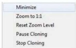
Image 5-5 Conference CloneView Context Menu
- Minimize: This minimizes the cloned image to show the desktop.
- Zoom to 1:1: Changes the scaling to 1 target pixel per source pixel. If the source resolution is larger than the target resolution, panning will be necessary to see the entire image. If the source resolution is sm than the target resolution, black boarders will show around the image. "Stretch to fill" has priority over this option.
- Reset Zoom Level: When "Stretch to fill" is selected in the Barco System Settings Control Panel, this will reset to the minimal zoom possible to make the stretched aspect ratio possible. When "Stretch to fill" is not selected, this option will reset the zoom to 1:1. When the image is already at the minimum zoom level option is grayed out.
- Pause Cloning: This suspends updates to the clone image; the source can continue to change while the target image remains static. Select it a second time to resume active cloning.
- Stop Cloning: Select this option to stop cloning on the current Display Controller. It has the same effect as clicking on the Stop Cloning button in the Barco System Settings Control Panel.
5.4.3 Configuration
Configuring Conference CloneView
- Add clone configuration: Click this button to define a new clone configuration.
- Clone From and Clone To: Click on one or more source displays in the Clone From list and one or more target displays from the Clone To list for the session. An active source cannot be used as a target, and an active target cannot be used as a source.
- Stretch to fill: If this is unchecked, the aspect ratio of the source displays will be preserved. If this is checked, the cloned image will be stretched to fill the target display(s) with the cloned image.
- Start/Stop: Clicking the Start button activates the clone session, and the button will change to Stop, which would end the session.
- Remove this configuration: Deletes this configuration.
5.5 DimView™
5.5.1 Description
Overview
The DimView feature reduces ambient light during diagnostic readings by dimming navigational displays when the cursor is moved off those displays. While the feature is intended for use with navigational heads, it is enabled on any display.
Image 5-6
Supported display controllers
DimView is supported on the MXRT-1450, MXRT-1451, and all MXRT-x500 or later display controllers.
5.5.2 Operation
Using DimView
DimView can be individually enabled on each display. All DimView-enabled displays can operate independently, or they can be configured to dim and brighten together.
5.5.3 Configuration
Configuring DimView
- Enable DimView for these displays: All displays that support DimView are listed in the configuration section. Click on the checkbox to enable the feature on that display.
- Dim/brighten selected displays together: When this box is checked, all DimView-enabled displays will brighten when the cursor is moved onto any one of those displays, and dim only when the cursor is of them.
• Luminance of dimmed displays: This slider bar sets the luminance while dimmed.
5.6 Film Clip

Film Clip is pending medical device clearance and is currently not available in all markets.
5.6.1 Description
Overview
Film Clip allows the user to view a physical radiological film by using the I-Luminate™ feature of the display as a virtual light box.

Image 5-7
Supported display controllers
When driven by an MXRT-x400 or later display controller, Film Clip can be enabled on the MDMG-5221 and MDMC-12133 displays.
5.6.2 Operation
Using Film Clip
The size and location of the film clip light box are programmable. It has an automatic time-out with a programmable duration. An optional hotkey can quickly turn the light box on or off.
Supported film sizes for both MDMG-5221 and MDMC-12133 include the 18 cm x 24 cm and 24 cm x the MDMC-12133 also supports the larger 34 cm x 43 cm size.
5.6.3 Configuration
Configuring Film Clip
- Enable Film Clip hotkey for these displays: All displays that support Film Clip are listed in the configuration section. Click on the checkbox to launch the feature on that display with the hotkey.
- Timeout: The slider bar sets the time-out period for Film Clip mode.
• Hotkey to enabled Film Clip: Click Clear to remove a hotkey. Click on the hotkey box to enter a new one.
• Position: This sets the location of the light box image on enabled displays.
• Size: This sets the size of the light box image to match the physical film dimensions.
5.7 FindCursor™
5.7.1 Description
Overview
The FindCursor feature provides a method to quickly locate the cursor on a system with multiple displays.

Image 5-8
Supported display controllers
FindCursor is supported on all MXRT-x400 or later display controllers.
Default behavior
FindCursor is enabled by default.
5.7.2 Operation
Using FindCursor
To quickly locate the cursor, hold down the hotkey (default: Control+Shift+F). The cursor location will be highlighted by a circle, which appears yellow on color displays and gray on grayscale displays.
5.7.3 Configuration
Configuring FindCursor
- Enable/Disable: Use the checkbox to enable or disable FindCursor.
- Hotkey: The currently selected hotkey is displayed in the edit box. To program a new hotkey, highlight the edit box, and input the new keystrokes. The change will take affect right away.
5.8 I-Luminate™

I-Luminate is pending medical device clearance and is currently not available in all markets.
5.8.1 Description
Overview
This feature boosts the luminance of supported displays.
Image 5-9
Supported display controllers
When driven by an MXRT-x400 or later display controller, I-Luminate can be enabled on supported displays, including MDMC-12133, MDMG-5221, and MDCG-5221.
5.8.2 Operation
Using I-Luminate
A hotkey will boost the luminance on all selected displays.
5.8.3 Configuration
Configuring I-Luminate
- Enable I-Luminate for these displays: All displays that support I-Luminate are listed in the configuration section. Click on the checkbox to enable the feature on that display.
- Hotkey to enabled I-Luminate: Click Clear to remove a hotkey. Click on the hotkey box to enter a new one.
- Timeout: The slider bar sets the time-out period for the I-Luminate mode.
5.9 Reading Environment
5.9.1 Description
Overview
The reading environment settings for diagnostic displays allow the user to specify the color temperature ar luminance of SteadyColor-calibrated displays. The reading environment for non-diagnostic displays allows the user to specify the maximum luminance on Barco clinical displays and third-party displays, however color temperature selection is not available.
Image 5-10
Supported display controllers
When driven by an MXRT-x500 or later display controller, the Reading Environment can be configured on MDMC-12133, MDNC-6121, MDCC-6530, MDCC-4430, Barco MDRC displays, and third-party displays.

Diagnostic reading environment configuration is available on Coronis Uniti displays that are calibrated with QAWeb 1.13.01 or later, on MDNC-6121 displays that are configured with QAWeb 1.13.10 or later, and on MDCC-6530 and MDCC-4430 displays calibrated by QAWeb Enterprise 2.: or later.
5.9.2 Operation
Using Reading Environment for SteadyColor Diagnostic Displays
The configuration of the Reading Environment is complimentary to the QAWeb settings. If the SteadyColor display is calibrated by the QAWeb 1.x Agent and the workstation is not connected to the QAWeb 1.x S all the controls in this section are available in the Barco System Settings Control Panel. If the workstation connected to the QAWeb 1.x Server, use the server to set the reading environment. If the display is cal by the QAWeb Enterprise Agent, only the white-point chromaticity is calibrated through the Barco System Settings Control Panel.
Configure the white point chromaticity, ambient light, color calibration model, and calibrated luminance to us preference. After the settings have been changed, the QAWeb Agent will check if it has calibration files f
new settings. If it does, it will upload the calibration data to the display, which may take 20-60 seconds. does not have the calibration files, it will calibrate the display to create them, which may take up to 10

When changes to the Reading Environment for Diagnostic Displays are made, the Barco System Settings Control Panel will indicate that changes are still in progress. Please let the system apply changes before proceeding with readings.
Using Reading Environment for Non-Diagnostic Displays
Reading Environment can be individually enabled on each non-diagnostic display to reduce its luminance. Unlike DimView, the luminance of these displays will not change with cursor movement. The Reading Environment feature can be used in conjunction with DimView.
5.9.3 Configuration
Configuring Reading Environment for Diagnostic Displays
- Use the settings QAWeb already has: When selected, reading environment settings for diagnostic displays are disabled in the Barco System Settings Control Panel.
- Suggest the following settings to QAWeb: When selected, the reading environments are modifiable.
- White point chromaticity: This selects between clearbase, bluebase, and native white points.
- Ambient light condition: This selects the expected ambient light condition based on reading room class.
• SteadyColor calibration: This selects the color calibration model of the SteadyColor display.
• Luminance of white: This slider sets the calibration luminance of the display.

In some installations with QAWeb, Ambient light condition, SteadyColor calibration, and Luminance of White do not appear in the Barco System Settings Control Panel. These can be configured in QAWeb with an appropriate image quality policy.
Configuring Reading Environment for Non-Diagnostic Displays
- Select the displays: All supported non-diagnostic displays are listed in the configuration section. Click on the checkbox to enable the feature on that display.
- Display luminance: This slider bar sets the luminance reduction for the selected displays.
5.10 Screen Capture
5.10.1 Description
Overview
The Screen Capture feature captures the desktop into an image, including the Intuitive Workflow features, such as SpotView.
Image 5-11
Supported display controllers
This feature is supported by MXRT-x400 and above display controllers.
5.10.2 Operation
Using Screen Capture
The screen capture is triggered through a hotkey. The user can choose to capture the image of the disp with the cursor to the clipboard. The user can also choose to capture an image of each display to a fil either PNG or PPM format.
5.10.3 Configuration
Configuring Screen Capture
• Hotkey: Click Clear to remove a hotkey. Click on the hotkey box to enter a new one.
- Copy captured image to Windows clipboard: Check this box to copy the image of the display with the cursor to the clipboard.
• Output directory: To save the capture images as files, enter a target location here.
- File format: Use these radio buttons to choose the file format as either PNG or PPM.
5.11 SingleView™
5.11.1 Description
Overview
SingleView enables the use of a Coronis Fusion display as a single display in the Windows desktop and eliminates any tearing down the center.
Image 5-12
Supported displays
When driven by an MXRT-x400 or later display controller, SingleView is supported on all Coronis Fusion displays.
5.11.2 Operation
Using SingleView
A button will switch all Coronis Fusion displays into SingleView, and another will switch all into DualView. Hotkeys are available for both actions.
When in SingleView, it is possible to have the left and right halves out of position, and a button will swap the two.
DualView is the preferred setting for most PACS application software.
5.11.3 Configuration
Configuring SingleView
- Enable SingleView: This check box will toggle between SingleView and DualView.
- Swap Left/Right: This can correct misaligned SingleView displays one at a time.
- Hotkeys: SingleView and DualView activations have individual hotkeys. Click Clear to remove a hotkey. Click on the hotkey box to enter a new one.
5.12 SmartCursor™
5.12.1 Description
Overview
The Barco SmartCursor feature prevents the cursor from becoming stuck on edges of adjacent displays of different sizes.
Image 5-13
Supported display controllers
SmartCursor is supported by all systems with an MXRT-x400 or later display controller.
5.12.2 Operation
Using SmartCursor
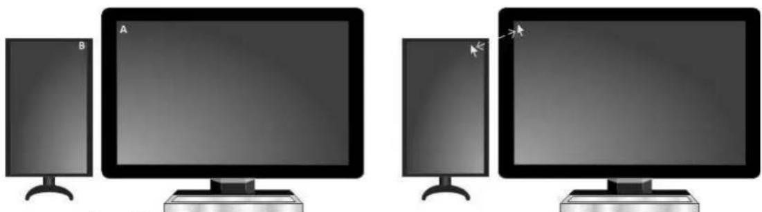
The SmartCursor operation in illustrated in Image 5-14.
Consider two points, A and B, on two displays of different sizes. Without SmartCursor, the cursor cannot move left from point A because it will be stuck on that edge. With SmartCursor, moving the cursor left from point A will move the cursor to point B. For symmetry, with SmartCursor moving to the right from point B, the cursor will appear back at point A.
natural_image
Two identical computer monitors, each with a speaker labeled A and a speaker labeled B, shown side by side (no text or symbols on screens)Image 5-14 SmartCursor moving left from point A and right from point B.
5.12.3 Configuration
Configuring SmartCursor
Enable: Click on this checkbox to turn SmartCursor on or off.
5.13 SoftGlow™
5.13.1 Description
Overview
Select Barco Coronis displays support SoftGlow. It consists of a task light, which sheds a light on the desktop, and a wall light, which provides ambient lighting for the reading room to reduce eye fatigue. The brightness each is configurable.
Image 5-15
Supported display controllers
When driven by an MXRT-x400 or later display controller, SoftGlow can be configured on MDMC-12133, MDCC-6530, and MDCC-4430 displays.
5.13.2 Operation
Using SoftGlow
The task and wall lights will be set to the SoftGlow settings when the user has logged on to the Barco display system.
5.13.3 Configuration
Configuring SoftGlow
- Task Light and Wall Light: Use these sliders to set the brightness of the lights. Click and enter 0 to shut the light off.
- Hotkey: When configured, this hotkey will toggle the task lights on and off. The wall lights are only controlled by the slider.
5.14 SpotView™

SpotView is pending medical device clearance and is currently not available in all markets.
5.14.1 Description
Overview
The SpotView feature allows focused observation during readings by dimming images outside a region of interest and optionally enhancing the contrast in the region of interest.
The SpotView Mag feature offers 2x zoom within the SpotView region of interest. SpotView Invert inverts the pixels in the region of interest. SpotView Align creates a bar-shaped region of interest, which can be rotated as needed. SpotView Align has 2 modes of operation, a straight bar, or a V-shaped bar.

Image 5-16
Supported displays and display controllers
When driven by an MXRT-x500 or later display controller, SpotView can be enabled on selected Barco Coronis, Nio and Mammography displays, including MDCC-6530, MDCC-6430, MDCC-6330, MDCC-4430, MDCC-4330, MDCC-4230, MDCG-5221, MDCG-3221, MDNC-6121, MDNC-3421, MDNC-3321, MDNC-2221, MDNG-5221, MDMG-5121, MDMG-5221 and MDMC-12133.
5.14.2 Operation
Using SpotView
SpotView highlights a region of interest. The region of interest is selected by the use of the Barco Touchpad or by the mouse and a hotkey (default: Control+Shift+X). To control SpotView with the touchpad, hold and move one finger. The highlighted region of interest is always bound to displays that support SpotView.

To show SpotView when the Barco Touchpad is in Mouse Emulation Mode, hold one finger then tap a second.
The default diameter of the region of interest is controllable in the Barco System Settings Control Panel. Dynamic Sizing is enabled, the diameter is also controllable with the scroll wheel when using the mouse, with a pinch gesture when using the Barco touchpad. When SpotView is released, it returns to the default
diameter on the next activation. When using the mouse, clicking on the scroll wheel will toggle between controlling the Dynamic Sizing of the spot and scrolling in the Windows application.
To enhance viewing on Coronis and Mammography displays, the SpotView feature boosts the luminance of the display, if supported. The boost feature will turn off after one minute of continuous use. To further viewing, the SpotView feature will optionally enhance the contrast of the region of interest. Contrast enhancement is not available with SpotView Align.
SpotView Mag highlights a region of interest, boosts luminance, and applies 2x zoom to the area. It is controlled through the Barco Touchpad or by the mouse and a hotkey (default: Control+Shift+Z). For the touchpad, while holding one finger to show SpotView, tap a second finger to toggle on (or off) SpotView Mag.
SpotView Invert inverts pixels in the region of interest. It is controlled through the Barco Touchpad or by a mouse and a hotkey (default: Control +Shift +S). For the touchpad, while holding one finger to show SpotView, double-tap a second finger to toggle on (or off) SpotView Invert. SpotView Invert can be used simultaneously with SpotView Mag with the Barco Touchpad or by a mouse and hotkey (default: Control +Shift+A).
When using the hotkey to turn on SpotView, the Spot will appear with the current cursor position being the center. When the Spot is moved onto a display that does not support the feature, it will not show the s
SpotView Align implements SpotView technology in different shapes to enable alternative uses. The two alternate shapes are a bar and a vee. They are only available through use of the Barco Touchpad, and both allow custom angles specified by the user.
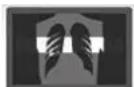
Image 5–17
To enable the SpotView Align bar shape, first hold one finger on the touchpad to show SpotView then hold two fingers on it to show SpotView Align. Rotate two fingers for the desired angle, and keep just one finger to lock the angle. The bar can be moved by dragging the one finger. The angle of SpotView Align can be adjusted again by rotating two fingers on the touchpad. While holding one finger to show SpotView Align, tap or double-tap a second finger to toggle on (or off) SpotView Mag or SpotView Invert.
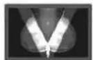
Image 5–18
To enable the SpotView Align vee shape, first enable the bar shape, then hold three fingers to show the mirror-image vee shape. Rotating two fingers will rotate the right bar, and the left image will follow. While holding finger to show SpotView Align, tap or double-tap a second finger to toggle on (or off) SpotView Mag or SpotView Invert.
5.14.3 Configuration
Configuring SpotView
- Enable SpotView for these displays: All displays that support SpotView are listed in the configuration section. Click on the checkbox to enable the feature on that display.
- Enable Dynamic Contrast Enhancement: Click on this checkbox to turn on the contrast enhancement feature. This is only available for the standard SpotView circle shape.
- Enable Dynamic Size Adjustment for spot: Click on this checkbox to allow the SpotView diameter to change with the scroll wheel or keypad pinch.
- Show cursor in spot: Enabling this feature shows the cursor when controlled by a mouse. The touchpad behavior is unaffected.
- Bar: Check this box to enable the SpotView Align bar shape by holding down two fingers on the touchpad.
- Vee: Check this box to enable the SpotView Align vee shape by holding down three fingers on the touchpad.
- Luminance outside of spot: This slider bar sets the luminance on SpotView enabled displays outside of the spot.
- SpotView size, SpotView Mag size, and SpotView Align Width: These sliders control the diameter of their spots and the width of the SpotView Align bar.
Note: These sizes are described in centimeters. The apparent size will vary due to parallax, rounding display size, and the shaded penumbra of the spot. It is not intended to be used alone to make exact measurements of body parts.
- Hotkeys: SpotView and SpotView Mag, both with and without SpotView Invert, have individual hotkeys. Click Clear to remove a hotkey. Click on the hotkey box to enter a new one.
5.15 Touchpad gestures
5.15.1 Description
Overview
In addition to controlling SpotView, the Barco Touchpad can control the cursor and allows the user to control PACS and other applications with multi-touch gestures and touchpad buttons. The user can program the gestures and buttons to send shortcut keystrokes recognized by the PACS system.

Image 5–19
Supported display controllers
The touchpad gestures are supported by all systems with an MXRT-x400 or later display controller and the Barco Touchpad CTH-480 or later.
5.15.2 Operation
Using the Barco Touchpad Mouse Emulation
When Mouse Emulation Mode is enabled, the user can control the cursor using the Barco Touchpad instead of a mouse. The gestures recognized in Mouse Emulation Mode are listed in the table below. To show SpotView with Mouse Emulation Mode enabled, hold one finger and tap a second.
| Touchpad gesture | Emulated Mouse action |
| Move one finger Move cursor | |
| Tap one finger | Left click |
| Double-tap one finger | Left double-click |
| Tap two fingers | Right click |
| Double-tap two fingers | Right double-click |
| Double-tap one finger, holding it the second time moving | left and drag |
| Double-tap two finger, holding one the second and moving | right click and drag |
| Pinch two fingers together | Control+scroll wheel down (Zoom out) |
| Pinch two fingers out | Control+scroll wheel up (Zoom in) |
| Drag two fingers up | Scroll wheel up |
| Drag two fingers down | Scroll wheel down |
| Drag two fingers left | Click scroll Wheel and drag left |
| Drag two fingers right | Click scroll Wheel and drag right |
Using the Barco Touchpad Gesture Recognition
The Barco Touchpad recognizes 10 two- and three-finger gestures: Two- and Three-finger Swipe Left, Two- and Three-finger Swipe Right, Two- and Three-finger Swipe Up, Two- and Three-finger Swipe Down, Two-finger Pinch In, and Two-finger Pinch Out. These are shown in the table below.
| Swipe Left Swipe Right | 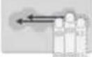 | 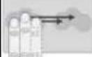 | |
| Swipe Up Swipe Down | 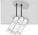 | 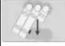 | |
| Pinch In Pinch Out |  |  |
Each gesture can be programmed to send keystroke shortcuts, as if those keys were pressed on the keyboard. These keystroke shortcuts can be used by the active application in Windows. The gesture can a single keystroke or send the keystroke continuously until the gesture ceases. Some gestures are used by default in Mouse Emulation Mode; those defaults can be overwritten in the Barco System Settings Control Panel.
5.15.3 Configuration
Configuring the Barco Touchpad
From the Barco System Settings Control Panel, navigate to the Touchpad Gestures section to associate the Barco Touchpad gestures with desired shortcut keys.
- Enable Mouse Emulation: Click on this checkbox to control the cursor with the touchpad.
• Speed: This slides controls the responsiveness of the cursor in Mouse Emulation Mode. - Emitted Shortcut: This field shows the currently defined keyboard shortcut for each gesture. Click on the field to define a new shortcut.
- Clear: Click the Clear button to remove the hotkey for a given gesture or button.
• Continuous: This checkbox enables continuous shortcut emission.
• Rate: This slide controls the rate of continuous shortcut emission. - Shortcut Description: Click on this free text field to describe the intention of the shortcut.
5.16 VirtualView™
5.16.1 Description
Overview
VirtualView gives the user additional real-estate on the screen by creating a virtual display in Windows without the need for an additional physical display on the desk. A virtual display is created for the user to use navigational head, or for other software, such as dictation. The user can set the location of the virtual di and when the cursor moves into that virtual area, or hotkey is triggered, the virtual display appears on the Windows desktop.
Image 5-20
Supported display controllers
VirtualView is supported by all systems with an MXRT-x500 or later display controller.
5.16.2 Operation
Using VirtualView
VirtualView creates a virtual display within the Windows desktop. In the Windows control panel, it appears as a normal display with a display number, and its resolution and location can be changed similarly to a physi display.
By moving the cursor to the virtual display location on the desktop, the virtual display appears on a physical display. VirtualView can also be activated and hidden by a hotkey (default: Control+Shift+V). It can be stretched to make the contents larger or shrunk to make the window take less desktop space. Windows applications can be dragged and dropped onto the virtual display, and they will show only when VirtualView is showing.
To promote usability with PACS applications, VirtualView has a visibility setting. In the Diagnostic visibility mode (default), it will appear on the top of all other windows, and in the Administrative visibility mode, it be hidden by other windows, including the PACS software.
The virtual display window has Minimize, Maximize, Restore, and Close buttons.
- Clicking the Minimize button hides VirtualView and creates an icon on the Task Bar, and clicking on the icon will restore it to its previous size and location.
- Clicking the Maximize button resizes VirtualView to the largest size possible on that physical display while maintaining aspect ratio, and that button will change to Restore.
- Clicking on the Restore button returns the maximized window to its previous size and location.
- Clicking the Close button does not terminate the VirtualView feature. It hides the window, and when shown again, it will appear in the default location and size.
5.16.3 Configuration
Configuring VirtualView through Barco System Settings Control Panel
- Connect: VirtualView is disabled by default. Click on this checkbox to connect a VirtualView display to the desktop.
Once VirtualView has been connected to the desktop through the Barco System Settings Control Panel, the VirtualView display will show up in the Windows Display Control Panel as Barco Virtual display, and can be controlled as a regular display on the desktop.
- Reset window size: This resets the virtual display window to 1-to-1 scaling.
- Configure Visibility: Selects between Diagnostic and Administrative visibility modes.
- Configure Hotkey: Specify a hotkey to show/hide virtual display window.
Configuring VirtualView through Windows Display Control Panel
The Windows Display Control Panel can be opened through the Barco System Settings Control Panel. Or, from the Control Panel, select Display, and select Screen Resolution. Or, click on the desktop a select Screen Resolution.
The Barco virtual display resolution and location on the Windows desktop can also be changed in the co panel in the same method as normal displays. VirtualView supports a large range of portrait and landscape resolutions.
Important information
6
6.1 Safety information
General recommendations
Read the safety and operating instructions before operating the device.
Retain safety and operating instructions for future reference.
Adhere to all warnings on the device and in the operating instructions manual.
Follow all instructions for operation and use.
Electrical Shock or Fire Hazard
To prevent electric shock or fire hazard, do not remove cover.
No serviceable parts inside. Refer servicing to qualified personnel.
Do not expose this apparatus to rain or moisture.
Modifications to the unit
Do not modify this equipment without authorization of the manufacturer.
Type of protection (Electrical)
Device with external power supply: Class I equipment.
Degree of safety (flammable anesthetic mixture)
Equipment not suitable for use in the presence of a flammable anesthetic mixture with air or with oxygen nitrous oxide.
6.2 Environmental information
Disposal Information
Waste Electrical and Electronic Equipment

This symbol on the product indicates that, under the European Directive 2012/19/EU governing waste from electrical and electronic equipment, this product must not be disposed of with other municipal waste. Please dispose of your waste equipment by handing it over to a designated collection point for the recycle waste electrical and electronic equipment. To prevent possible harm to the environment or human health fi uncontrolled waste disposal, please separate these items from other types of waste and recycle them responsibly to promote the sustainable reuse of material resources.
For more information about recycling of this product, please contact your local city office or your municipal waste disposal service.
For details, please visit the Barco website at: http://www.barco.com/AboutBarco/weee
Turkey RoHS compliance

[Republic of Turkey: In conformity with the WEEE Regulation]
中国大陆 RoHS
Chinese Mainland RoHS
According to the “Management Methods for the Restriction of the Use of Hazardous Substances in Electrical and Electronic Products” (Also called RoHS of Chinese Mainland), the table below lists the names and contents of toxic and/or hazardous substances that Barco’s product may contain. The RoHS of Chinese Mainland is included in the MCV standard of the Ministry of Information Industry of China, in the section “Limit Requirements of toxic substances in Electronic Information Products”.
| 零件项目(名称)Component name | 有毒有害物质或元素Hazardous substances and elements | |||||
| 铅Pb | 汞Hg | 镉Cd | 六价铬Cr6+ | 多溴联苯PBB | 多溴二苯醚PBDE | |
| 印制电路配件Printed Circuit Assemblies | x o o o | o o | ||||
| 本表格依据SJ/T 11364的规定编制This table is prepared in accordance with the provisions of SJ/T 11364.o:表示该有毒有害物质在该部件所有均质材料中的含量均在 GB/T 26572 标准规定的限量要求以下.o:Indicates that this toxic or hazardous substance contained in all of the homogeneous materials for this is below the limit requirement in GB/T 26572.x:表示该有毒有害物质至少在该部件的某一均质材料中的含量超出 GB/T 26572 标准规定的限量要求.x:Indicates that this toxic or hazardous substance contained in at least one of the homogeneous material used for this part is above the limit requirement in GB/T 26572. | ||||||
All Electronic Information Products (EIP) that are sold within Chinese Mainland must comply with the “Marking for the restriction of the use of hazardous substances in electrical and electronic product” of Chinese Mainland, marked with the Environmental Friendly Use Period (EFUP) logo. The number inside the EFUP logo that Barco uses (please refer to the photo) is based on the “General guidelines of environment-friendly use period of electronic information products” of Chinese Mainland.

台灣 RoHS
Taiwan RoHS
限用物質含有情況標示聲明書
Declaration of the Presence Condition of the Restricted Substances Marking
| 設備名稱:视频显示卡.型號(型式):102-c58708-01;MXRT-5600;MXRT-7600Equipment name . Type designation (Type) | ||||||
| 單元Unit | 限用物質及其化學符號Restricted substances and its chemical symbols | |||||
| 鉛(Pb) | 汞(Hg) | 鎘(Cd) | 六價鉻( Cr^+6 ) | 多溴聯苯(PBB) | 多溴二苯醚(PBDE) | |
| 风扇散热器Fansink | - | ○ ○ | ○ | ○ | ○ | |
| 电路板Circuit Board | - | ○ ○ | ○ | ○ | ○ | |
| 托架Bracket | ○ | ○ ○ | ○ | ○ | ○ | |
| 拧Screw | ○ ○ | ○ ○ ○ ○ | ||||
| 備考1. “超出0.1 wt %”及“超出0.01 wt %”係指限用物質之百分比含量超出百分比含量基準值Note 1: “Exceeding 0.1 wt %” and “exceeding 0.01 wt %” indicate that the percentage content of the restricted substance exceeds the reference percentage value of presence condition備考2. “○”係指該項限用物質之百分比含量未超出百分比含量基準值Note 2: “○” indicates that the percentage content of the restricted substance does not exceed the percentage of reference value of presence.備考3. “-”係指該項限用物質為排除項目Note 3: The “-” indicates that the restricted substance corresponds to the exemption | ||||||
6.3 Regulatory compliance information
6.3.1 Display Controllers
Manufacturing country
The manufacturing country of the product is indicated on the product label ("Made in ...").
Importers contact information
To find your local importer, contact one of Barco's regional offices via the contact information provided on our website (www.barco.com).
FCC class B
This device complies with Part 15 of the FCC Rules. Operation is subject to the following two conditions: this device may not cause harmful interference, and (2) this device must accept any interference received, including interference that may cause undesired operation.
This device has been tested and found to comply with the limits for a Class B digital device, pursuant to 15 of the FCC Rules. These limits are designed to provide reasonable protection against harmful interferer in a residential installation. This device generates, uses and can radiate radio frequency energy and, if no installed and used in accordance with the instructions, may cause harmful interference to radio communications. However, there is no guarantee that interference will not occur in a particular installation. This device does cause harmful interference to radio or television reception, which can be determined by turning the device off and on, the user is encouraged to try to correct the interference by one or more following measures:
• Reorient or relocate the receiving antenna.
- Increase the separation between the device and receiver.
- Connect the device into an outlet on a circuit different from that to which the receiver is connected.
- Consult the dealer or an experienced radio/TV technician for help.
Changes or modifications not expressly approved by the party responsible for compliance could void the user's authority to operate the equipment.
FCC responsible: Barco Inc., 3059 Premiere Parkway Suite 400, 30097 Duluth GA, United States, Tel: +1 678 475 8000
6.3.2 Intuitive Workflow Tools

Only the intuitive workflow tools SpotView, I-luminate, FilmClip and Application Appearance Manager (AAM) are in scope of this section.
Indications for use
The Intuitive Workflow Tools are intended to be used as accessories for image enhancement in diagnostic displays.
Intended usage environment
There are no specific intended conditions for use.
Contra-indications
Not applicable.
Intended users
The Intuitive Workflow Tools are intended to be used by trained medical practitioners.
6.4 Explanation of symbols
Overview
On the Display Controller or in the Intuitive Workflow Tools user interface, you may find the following syr (nonrestrictive list):
 | Indicates the device meets the requirements of the applicable EC directives |
 1639 1639 | Indicates the device meets the requirements of the applicable EC directives |
 | Indicates the device is in compliance with Part 15 of the FCC rules (Class A or Class B) |
 | Indicates the device is approved according to the UL regulations |
 | Indicates the device is approved according to the UL regulations for Canada and US |
 SAFETY US-CAE352529 SAFETY US-CAE352529 | Indicates the device is approved according to the UL regulations for Canada and US |
 | Indicates the device is approved according to the UL Demko regulations |
 | Indicates the device is approved according to the VCCI regulations |
 | Indicates the device is approved according to the KC regulations |
 | Indicates the device is approved according to the BSMI regulations |
 | Indicates the device is approved according to the PSE regulations |
 | Indicates the device is approved according to the RCM regulations |
 | Indicates the device is approved according to the EAC regulations |
 | Caution: Federal law (United Stated of America) restricts this device to sale by or on the order of a licensed healthcare practitioner. |
IS 13252 (Part 1)IFC 60950-1 R-xxxxxxxxwww.bis.gov.in R-xxxxxxxxwww.bis.gov.in | Indicates the device is approved according to the BIS regulations |
 | Indicates the USB connectors on the device |
 | Indicates the DisplayPort connectors on the device |
 | Indicates the legal manufacturer |
 | Indicates the manufacturing date |
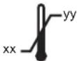 | Indicates the temperature limitation for the device to safely operate within specs |
 | Indicates the device serial number |
 | Indicates the device part number or catalogue number |
 | Warning: dangerous voltage |
 | Caution |
 | Consult the Instructions For Use |
 eIFU indicator eIFU indicator | Consult the Electronic Instructions For Use |
 | Indicates this device must not be thrown in the trash but must be recycled, according to the European WEEE (Waste Electrical and Electronic Equipment) directive |
 | Indicates Direct Current (DC) |
 | Indicates Alternating Current (AC) |
 | Stand-by |
 | Equipotentiality |
 | Protective earth (ground) |
6.5 Legal disclaimer
Disclaimer notice
Although every attempt has been made to achieve technical accuracy in this document, we assume no responsibility for errors that may be found. Our goal is to provide you with the most accurate and usable documentation possible; if you discover errors, please let us know.
Barco software products are the property of Barco. They are distributed under copyright by Barco NV or Inc., for use only under the specific terms of a software license agreement between Barco NV or Barco and the licensee. No other use, duplication, or disclosure of a Barco software product, in any form, is authorized.
The specifications of Barco products are subject to change without notice.
Trademarks
All trademarks and registered trademarks are property of their respective owners.
Copyright notice
This document is copyrighted. All rights are reserved. Neither this document, nor any part of it, may be reproduced or copied in any form or by any means - graphical, electronic, or mechanical including photocopying, taping or information storage and retrieval systems - without written permission of Barco.
© 2020 Barco NV all rights reserved.
Privacy policy
Barco is concerned about respecting the privacy of our users. Please see our privacy policy on our web http://www.barco.com/en/about-barco/legal/privacy-policy to learn more.
6.6 Technical specifications

Check with local service representatives for specifications if your card is not listed.
MXRT-2600
| Product acronym MXRT-2600 | |
| Bus compatibility PCIe Gen3 | x16 (wired x8) |
| Power consumption 26 Watt | |
| Form factor 168 mm (L) x 68 mm (H) single PCIe slot wide | |
| Operating system | Windows 7 – 32/64-bit, Windows 8.1 – 64-bit, Windows 10 – 64-bit |
| Platforms Intel® and AMD architectures | |
| Graphics accelerator ATI FirePro | |
| Graphics memory 2 GB DDR3 | |
| Memory interface 128-bit | |
| Memory bandwidth 28.8 GB/s | |
| Pixel depth | 32-bit pixels (supports 8-bit and 10-bit per color channel) |
| Electrical standard | DisplayPort complying to v1.2a |
| Connectors | 2x DisplayPort |
| Supported resolutions | Up to 6MP color |
| DirectX support | Microsoft® DirectX v11.2, Vertex Shader 5.0, Pixel Shader 5.0 |
| OpenGL support | OpenGL 4.4 |
| OpenCL support | OpenCL 1.2 |
| Approvals and compliance | FCC Part 15 Class B, CE EN 55022 Limit B, EN 55024, UL-6 CNS, CISPR- 22/24, IEC609050-1, VCCI, CSA C22.2, EU RoHS d (2011/65/EU), Certificate of Information & Communication Equipment (Republic of Korea) |
| Operating temperature | 0° to 55°C (32° to 131° F) |
MXRT-2700
| Product acronym MXRT-2700 | |
| Bus compatibility PCIe Gen3 | x16 (wired x8) |
| Power consumption 35 Watt | |
| Form factor 168 mm (L) x 68 mm (H) single PCIe slot wide | |
| Operating system Windows 7 | - 64-bit, Windows 10 - 64-bit |
| Platforms Intel® and AMD architectures | |
| Graphics accelerator AMD Radeon Pro | |
| Graphics memory 2 GB DDR5 | |
| Memory interface 64-bit | |
| Memory bandwidth 48 GB/s | |
| Pixel depth | 32-bit pixels (supports 8-bit and 10-bit per color channel) |
| Electrical standard | DisplayPort complying to v1.4 |
| Connectors | 2x Mini DisplayPort1x DisplayPort |
| Supported resolutions | Up to 6MP color |
| DirectX support | Microsoft® DirectX v12, Shader Model 5.1 |
| OpenGL support OpenGL 4.5 | |
| OpenCL support OpenCL 2.0 | |
| Vulkan support Vulkan 1.1 | |
| Approvals and compliance FO | C Part 15 Class B, CE EN 55032 Limit B, EN 55024, UL-60950-1, BMSI CNS, CISPR- 32/24, IEC609050-1, VCCI, CSA C22.2, EU RoHS directive (2011/65/EU), Certificate of Information & Communication Equipment (Republic of Korea) |
| Operating temperature 0° to | 55°C (32° to 131° F) |
MXRT-4700
| Product acronym MXRT-4700 | |
| Bus compatibility PCIe Gen3 | x16 (wired x8) |
| Power consumption 50 Watt | |
| Form factor 168 mm (L) x 68 mm (H) single PCIe slot wide | |
| Operating system Windows 7 | - 64-bit, Windows 10 - 64-bit |
| Platforms Intel® and AMD architectures | |
| Graphics accelerator | AMD Radeon Pro |
| Graphics memory | 4 GB DDR5 |
| Memory interface | 128-bit |
| Memory bandwidth | 96 GB/s |
| Pixel depth | 32-bit pixels (supports 8-bit and 10-bit per color channel) |
| Electrical standard | DisplayPort complying to v1.4 |
| Connectors | 2x Mini DisplayPort1x DisplayPort |
| Supported resolutions | Up to 8MP color |
| DirectX support | Microsoft® DirectX v12, Shader Model 5.1 |
| OpenGL support | OpenGL 4.5 |
| OpenCL support | OpenCL 2.0 |
| Vulkan support | Vulkan 1.1 |
| Approvals and compliance | FCC Part 15 Class B, CE EN 55032 Limit B, EN 55024, UL-60950-1, BN CNS, CISPR- 32/24, IEC609050-1, VCCI, CSA C22.2, EU RoHS directive (2011/65/EU), Certificate of Information & Communication Equipment (Republic of Korea) |
| Operating temperature 0° to | 55°C (32° to 131° F) |
MXRT-5600
| Product acronym MXRT-5600 | |
| Bus compatibility PCIe Gen3 | x16 |
| Power consumption | 75 Watt |
| Form factor | 172 mm (L) x 110 mm (H) single PCIe slot wide |
| Operating system | Windows 7 – 32/64-bit, Windows 8.1 – 64-bit, Windows 10 – 64-bit |
| Platforms | Intel® and AMD architectures |
| Graphics accelerator | ATI FirePro |
| Graphics memory 4 GB GDDR5 | |
| Memory interface | 128-bit |
| Memory bandwidth | 96 GB/s |
| Pixel depth | 32-bit pixels (supports 8-bit and 10-bit per color channel) |
| Electrical standard | DisplayPort complying to v1.2a |
| Connectors 4x DisplayPort | |
| Supported resolutions | Up to 12MP color and 10MP grayscale |
| DirectX support | Microsoft® DirectX v11.2, Vertex Shader 5.0, Pixel Shader 5.0 |
| OpenGL support | OpenGL 4.4 |
| OpenCL support OpenCL 1.2 | |
| Approvals and compliance FC | C Part 15 Class B, CE EN 55022 Limit B, EN 55024, UL-60950-1, BMSI CNS, CISPR- 22/24, IEC609050-1, VCCI, CSA C22.2, EU RoHS directive (2011/65/EU), Certificate of Information & Communication Equipment (Republic of Korea) |
| Operating temperature 0° to | 45°C (32° to 113° F) |
MXRT-6700
| Product acronym MXRT-6700 | |
| Bus compatibility PCIe Gen3 | x16 |
| Power consumption 75 Watt | |
| Form factor 173 mm (L) x | 112 mm (H) single PCIe slot wide |
| Operating system Windows 7 | - 64-bit, Windows 10 - 64-bit |
| Platforms Intel® and AMD architectures | |
| Graphics accelerator AMD Radeon Pro | |
| Graphics memory 8 GB DDR5 | |
| Memory interface 256-bit | |
| Memory bandwidth | 160 GB/s |
| Pixel depth | 32-bit pixels (supports 8-bit and 10-bit per color channel) |
| Electrical standard | DisplayPort complying to v1.4 |
| Connectors | 4x DisplayPort |
| Supported resolutions | Up to 12MP color and 10MP grayscale |
| DirectX support | Microsoft® DirectX v12, Shader Model 5.1 |
| OpenGL support | OpenGL 4.5 |
| OpenCL support | OpenCL 2.0 |
| Vulkan support | Vulkan 1.1 |
| Approvals and compliance | FCC Part 15 Class B, CE EN 55032 Limit B, EN 55024, UL-6 CNS, CISPR- 32/24, IEC609050-1, VCCI, CSA C22.2, EU RoHS d (2011/65/EU), Certificate of Information & Communication Equipment (Republic of Korea) |
| Operating temperature | 0° to 55°C (32° to 131° F) |
0950-1, BV directive
MXRT-7600
| Product acronym MXRT-7600 | |
| Bus compatibility | PCIe Gen3 x16 |
| Power consumption | 150 Watt |
| Power connector | One 2x3 power connector |
| Form factor | 248 mm (L) x 110 mm (H) single PCIe slot wide |
| Operating system | Windows 7 – 32/64-bit, Windows 8.1 – 64-bit, Windows 10 – 64-bit |
| Platforms | Intel® and AMD architectures |
| Graphics accelerator | ATI FirePro |
| Graphics memory 8 GB GDDR5 | |
| Memory interface | 256-bit |
| Memory bandwidth | 160 GB/s |
| Pixel depth | 32-bit pixels (supports 8-bit and 10-bit per color channel) |
| Electrical standard | DisplayPort complying to v1.2 |
| Connectors | 4x DisplayPort |
| Supported resolutions | Up to 12MP color and 10MP grayscale |
| DirectX support | Microsoft® DirectX v11.2, Vertex Shader 5.0, Pixel Shader 5.0 |
| OpenGL support | OpenGL 4.4 |
| OpenCL support OpenCL 1.2 | |
| Approvals and compliance FCC | C Part 15 Class B, CE EN 55022 Limit B, EN 55024, UL-60950-1, BMSI CNS, CISPR- 22/24, IEC609050-1, VCCI, CSA C22.2, EU RoHS directive (2011/65/EU), Certificate of Information & Communication Equipment (Republic of Korea) |
| Operating temperature 0° to 45°C (32° to 113° F) | |
MXRT-8700
| Product acronym MXRT-8700 | |
| Bus compatibility PCIe Gen3 | x16 |
| Power consumption 135 Watt | |
| Power connector One 2x3 power connector | |
| Form factor 241 mm (L) x 112 mm (H) single PCIe slot wide | |
| Operating system Windows 7 | - 64-bit, Windows 10 - 64-bit |
| Platforms Intel® and AMD architectures | |
| Graphics accelerator AMD Radeon Pro | |
| Graphics memory 16 GB DDR5 | |
| Memory interface 256-bit | |
| Memory bandwidth 224 GB/s | |
| Pixel depth | 32-bit pixels (supports 8-bit and 10-bit per color channel) |
| Electrical standard | DisplayPort complying to v1.4 |
| Connectors | 6x Mini DisplayPort |
| Supported resolutions | Up to 12MP color and 10MP grayscale |
| DirectX support | Microsoft® DirectX v12, Shader Model 5.1 |
| OpenGL support | OpenGL 4.5 |
| OpenCL support | OpenCL 2.0 |
| Vulkan support | Vulkan 1.1 |
| Approvals and compliance | FCC Part 15 Class B, CE EN 55032 Limit B, EN 55024, UL-6 CNS, CISPR- 32/24, IEC609050-1, VCCI, CSA C22.2, EU RoHS d (2011/65/EU), Certificate of Information & Communication Equipment (Republic of Korea) |
| Operating temperature | 0° to 55°C (32° to 131° F) |
0950-1, BN directive

Barco NV
President Kennedypark 35
8500 Kortrijk
Belgium

1639
SpotView, I-Luminate,
Film Clip, Application
Appearance Manager


MXRTs
- Display Controller and Intuitive Workflow Tools
- User Guide
- Table of contents
- Welcome! 7
- Display Controller installation 9
- Driver and software installation....15
- Configuring Barco displays in Windows 21
- Driver and Intuitive Workflow Tools 25
- Important information....43
- Welcome!
- 1
- About the product
- Overview
- What's in the box
- Contents
- Display Controller installation
- 2
- Which Display Controller ?
- Display Controller range
- Installing a Barco Display Controller
- Guidance
- Which PCIe slot to use
- Installation procedure
- How to install
- Connecting your Barco Displays
- IO-Panel for the Barco MXRT-2600
- IO-Panel for the Barco MXRT-2700 & MXRT-4700
- IO-Panel for the Barco MXRT-8700
- Dongles
- About
- Passive Single-Link Dongle
- Active Single-Link Dongle
- Active Dual-Link Dongle
- Shipping the Barco Display Controller
- Driver and software installation
- 3
- Introduction
- Prerequisites
- Installation procedure
- Installation procedure
- Silent installation
- Configure silent installation options
- Reboot
- Installation options
- Configure installation options
- Install driver in 24-bit
- Install driver with Coronis Fusion displays in SingleView mode
- Install driver with VirtualView enabled
- After installation
- Installation verification
- Automatic display configuration
- Upgrade drivers
- Uninstallation
- Uninstalling the drivers and software
- Barco System Cleaner
- Configuring Barco displays in Windows
- 4
- Display resolution
- Changing resolutions
- Software rotation
- Configuring screen orientation
- Night light
- Disabling Night light
- Driver and Intuitive Workflow Tools
- 5
- Barco System Settings Control Panel
- Description
- Operation
- Accessing the Barco System Settings Control Panel
- Layout of the Barco System Settings Control Panel
- Profile management
- Version information of the Intuitive Workflow Tools
- Version(s) covered in this user guide
- To find your version of the Intuitive Workflow Tools
- Compatibility of the Intuitive Workflow Tools
- To open the Intuitive Workflow Tools compatibility chart
- Application Appearance Manager
- Description
- Supported display controllers
- Operation
- Using Application Appearance Manager
- Configuration
- Configuring color management
- Color and Grayscale Depth
- Description
- Operation
- Using 30-bit desktop
- Configuration
- Configuring color depth
- Conference CloneView™
- Description
- Operation
- Using Conference CloneView
- Configuration
- Configuring Conference CloneView
- DimView™
- Description
- Operation
- Using DimView
- Configuration
- Configuring DimView
- Film Clip
- Description
- Operation
- Using Film Clip
- Configuration
- Configuring Film Clip
- FindCursor™
- Description
- Default behavior
- Operation
- Using FindCursor
- Configuration
- Configuring FindCursor
- I-Luminate™
- Description
- Operation
- Using I-Luminate
- Configuration
- Configuring I-Luminate
- Reading Environment
- Description
- Operation
- Using Reading Environment for SteadyColor Diagnostic Displays
- Using Reading Environment for Non-Diagnostic Displays
- Configuration
- Configuring Reading Environment for Diagnostic Displays
- Configuring Reading Environment for Non-Diagnostic Displays
- Screen Capture
- Description
- Operation
- Using Screen Capture
- Configuration
- Configuring Screen Capture
- SingleView™
- Description
- Supported displays
- Operation
- Using SingleView
- Configuration
- Configuring SingleView
- SmartCursor™
- Description
- Operation
- Using SmartCursor
- Configuration
- Configuring SmartCursor
- SoftGlow™
- Description
- Operation
- Using SoftGlow
- Configuration
- Configuring SoftGlow
- SpotView™
- Description
- Supported displays and display controllers
- Operation
- Using SpotView
- Configuration
- Configuring SpotView
- Touchpad gestures
- Description
- Operation
- Using the Barco Touchpad Mouse Emulation
- Using the Barco Touchpad Gesture Recognition
- Configuration
- Configuring the Barco Touchpad
- VirtualView™
- Description
- Operation
- Using VirtualView
- Configuration
- Configuring VirtualView through Barco System Settings Control Panel
- Configuring VirtualView through Windows Display Control Panel
- Important information
- 6
- Safety information
- General recommendations
- Electrical Shock or Fire Hazard
- Modifications to the unit
- Type of protection (Electrical)
- Degree of safety (flammable anesthetic mixture)
- Environmental information
- Disposal Information
- Turkey RoHS compliance
- 中国大陆 RoHS
- 台灣 RoHS
- Regulatory compliance information
- Display Controllers
- Manufacturing country
- Importers contact information
- FCC class B
- Intuitive Workflow Tools
- Indications for use
- Intended usage environment
- Contra-indications
- Intended users
- Explanation of symbols
- Legal disclaimer
- Disclaimer notice
- Trademarks
- Copyright notice
- Privacy policy
- Technical specifications
Brand : Barco
Model : MXRT-4700
Category : Monitor