RCS-1000 - Controller DataVideo - Free user manual and instructions
Find the device manual for free RCS-1000 DataVideo in PDF.


| Product Type | Controller |
| Brand | DataVideo |
| Model | RCS-1000 |
| Dimensions (W x H x D) | 200 x 150 x 50 mm |
| Weight | 0.5 kg |
| Power Supply | USB 5V DC |
| Power Consumption | 2.5 W |
| Connection Interface | USB Type-B |
| Button Count | 12 programmable buttons |
| Rotary Encoders | 2 |
| Joystick | 1 |
| LED Indicators | Per button (RGB) |
| Compatible Software | DataVideo switchers, OBS, vMix |
| Main Functions | Camera switching, PTZ control, audio mixing, effects |
| Maintenance | Clean with dry cloth; avoid liquids |
| Safety | Use only included USB cable; do not disassemble |
| Spare Parts | Replacement buttons, USB cable available |
| Repairability | Modular design; serviceable by authorized technicians |
| Operating Temperature | 0°C to 40°C |
| Storage Temperature | -20°C to 60°C |
| Humidity | 20% to 80% non-condensing |
| Included Accessories | USB cable, quick start guide |
Frequently Asked Questions - RCS-1000 DataVideo
User questions about RCS-1000 DataVideo
0 question about this device. Answer the ones you know or ask your own.
Ask a new question about this device
Download the instructions for your Controller in PDF format for free! Find your manual RCS-1000 - DataVideo and take your electronic device back in hand. On this page are published all the documents necessary for the use of your device. RCS-1000 by DataVideo.
USER MANUAL RCS-1000 DataVideo
datavideo
RCS-1000
QUICK START GUIDE
NOVEMBER 2017 - VERSION 2.1.4
INTRODUCTION
The RCS-1000 is an app for either iPad (iOS) or Android (Google) tablets which can be downloaded from the App Store (iOS) or Play Store (Google). RCS-1000 is designed to control certain Datavideo products including the SE-1200MU (6-input switcher), up to 4 PTC-150/PTC-150T cameras (HD PTZ cameras) and as HDR-60/70 (HD recorder). Once RCS-1000 and Datavideo devices are connected to a “network” you will be able to switch an event, control the cameras with presets as well as start/stop recording - all from one interface.
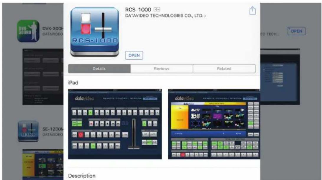
Fig 1. Application Download
CONNECT
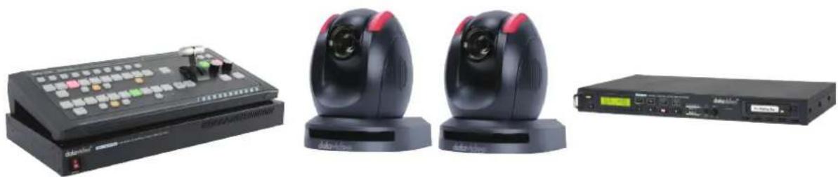
- All of the datavideo devices must be connected to the same network via a LAN (RJ-45 cable connection) with the exception of the recorder. For this example we will be using two datavideo PTC-150 cameras along with an SE-1200MU switcher and one HDR-70 recorder. The RCS-1000 software will be running on iOS however, the Android configuration is similar. In this quickstart, we will explain how to configure each device.
natural_image
Product photo of a black audio recording equipment including a control panel, two identical earphones, and a CD-ROM (no visible text or symbols)Fig 2. SE-1200MU & RMC-260, PTC-150s, HDR-70
- Once the RCS-1000 is installed on a tablet, make sure you're connected wirelessly to the same network as the cabled devices.
- Make sure the dip switches 1 and 4 on the bottom of the PTC-150(T) have been moved to the on (Top) position as show below in Fig 3:
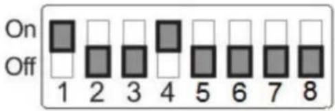
Fig 3. Dip Switches
- Connect the DVIP output of the camera to the router using a network cable as shown below in Fig 4:
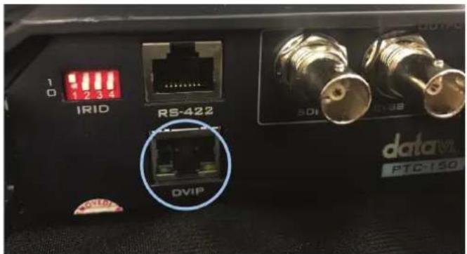
Fig 4. DVIP Input
- Press "Menu" on the cameras included IR remote to access the on screen display menu of the PTC-150(T). Arrow down to option "4 Remote Control" and press enter. Arrow down to "4: SET DVIP" and press enter, make sure the DVIP Baud rate is set to 115200 as shown below in Fig 5:
Set the DVIP baud rate to 115200
![[SET DVIP] 1: DVIP BAUDRATE: 115200 2: ESCAPE](/content/2026/05/980931/images/8943e67513fe6bddbfbefa6ac4ab3758103bdb5808d6e17e593c1e32aef45122.jpg)
Fig 5. DVIP Input
- If you only desire PTC-150 camera control, it is not necessary to have a SE-1200MU connected to the network, however if switching is also desired, connect the SE-1200MU to the same network (see Fig 6)
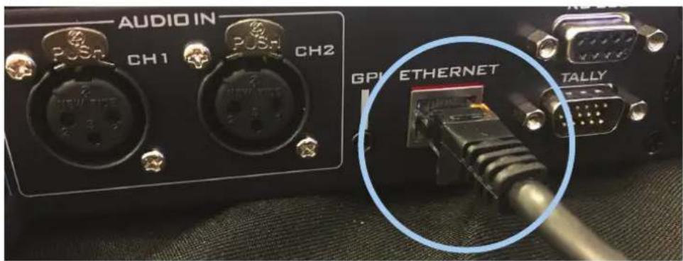
Fig 6. SE-1200MU Network Connection
-
Connect the HDR-60/70 recorder to the SE-1200 via a DSUB-9 (serial) male to male crossover cable, if remote control recording is desired.
-
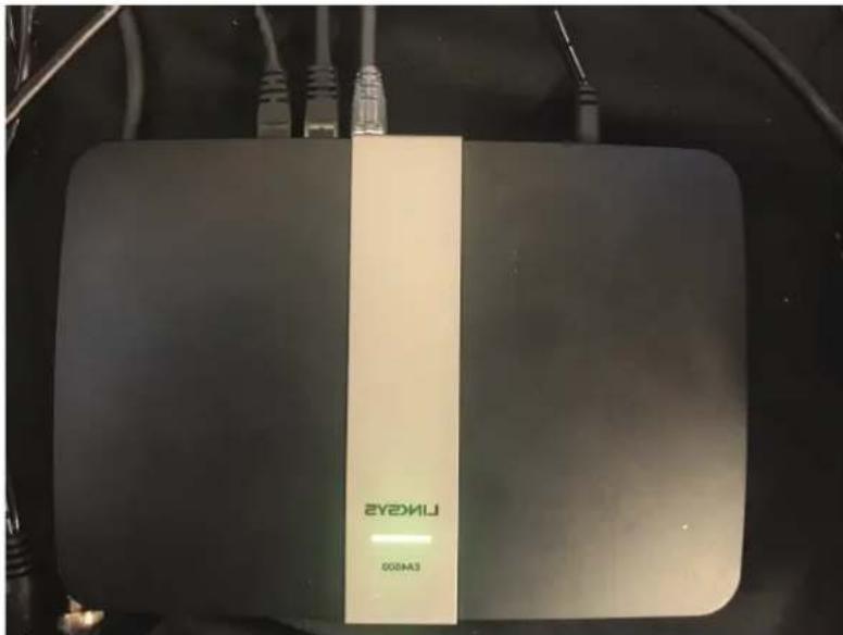
In this example, the following devices are connected to the network: 1-PTC-150, 1-SE-1200MU, 1-RCS-1000 (connected wirelessly to the router). However, up to 3 additional PTC-150(T) cameras could also be connected to this network.
natural_image
Front view of a black wireless router device labeled '200003' with visible wiring and connectors (no readable text beyond branding)Fig 7. Router Connections
- Each device will need to have a unique static IP address. The default address range for each device is typically 192.168.100.100. In order to change the Static IP address (without the assistance of a computer) you can install the DVIP APP from the App Store or Google Play Store.
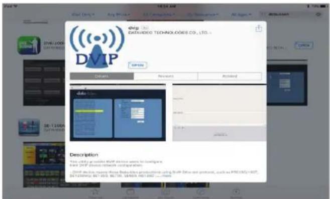
Fig 8. DVIP App Download
This app will search your network to locate all the corresponding datavideo device IP addresses which are connected to your network. Make sure that you select "Using Fixed IP Mode" on the interface. With your tablet, you can manually change the IP address. In this example, the camera IP was changed to 192.168.100.103, remember to select the "Save" button and to cycle the power on your devices. Once all of your connected datavideo devices have a unique IP address, you are now ready to utilize the RCS-1000 App.
Here is a typical device IP Range setup for the RCS-1000:
SE-1200MU - IP of 192.168.100.101
PTC-150 #1 - IP of 192.168.100.102
PTC-150 #2 - IP of 192.168.100.103
PTC-150 #3 - IP of 192.168.100.104
PTC-150 #4 - IP of 192.168.100.105
![datavideo Number of Devices 3 HOST-NAME0695D7[00:07:36:06:05:D7] DVIP-HostName[08:07:36:04:03:5E] SR-1290_161[60:87:36:07:07:E9] Name HOST-NAME0605D7 MAC address 00:07:36:06:05:H7 Using DHCP Mode Using Fixed IP Node IP address 192.168.100.102 Mask 255.255.255.0 Gateway 192.168.100.1 Primary DNS 8.8.9.8 Secondary DNS 8.8.4.4 Save](/content/2026/05/980931/images/028649028801c650df7ba1b3870a902cacfb3c1e22f18dc62fcb5ddb114d3449.jpg)
Fig 9. IP Setup
- Open the RCS-1000 app on your tablet.
- OncetheapplaunchesitmightpromptfortheIPaddressofyourtablet.Scrolldowntoselectthedevice which falls into theIP range of 192.168.100.1_. The software might take approximately 30 seconds to connect to each of your devices, you will see a rotating dotted circle until this is completed.
CONTROL
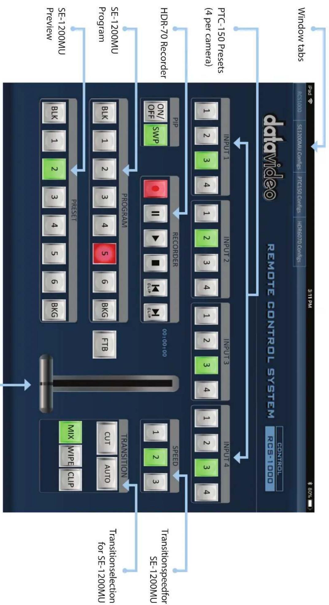
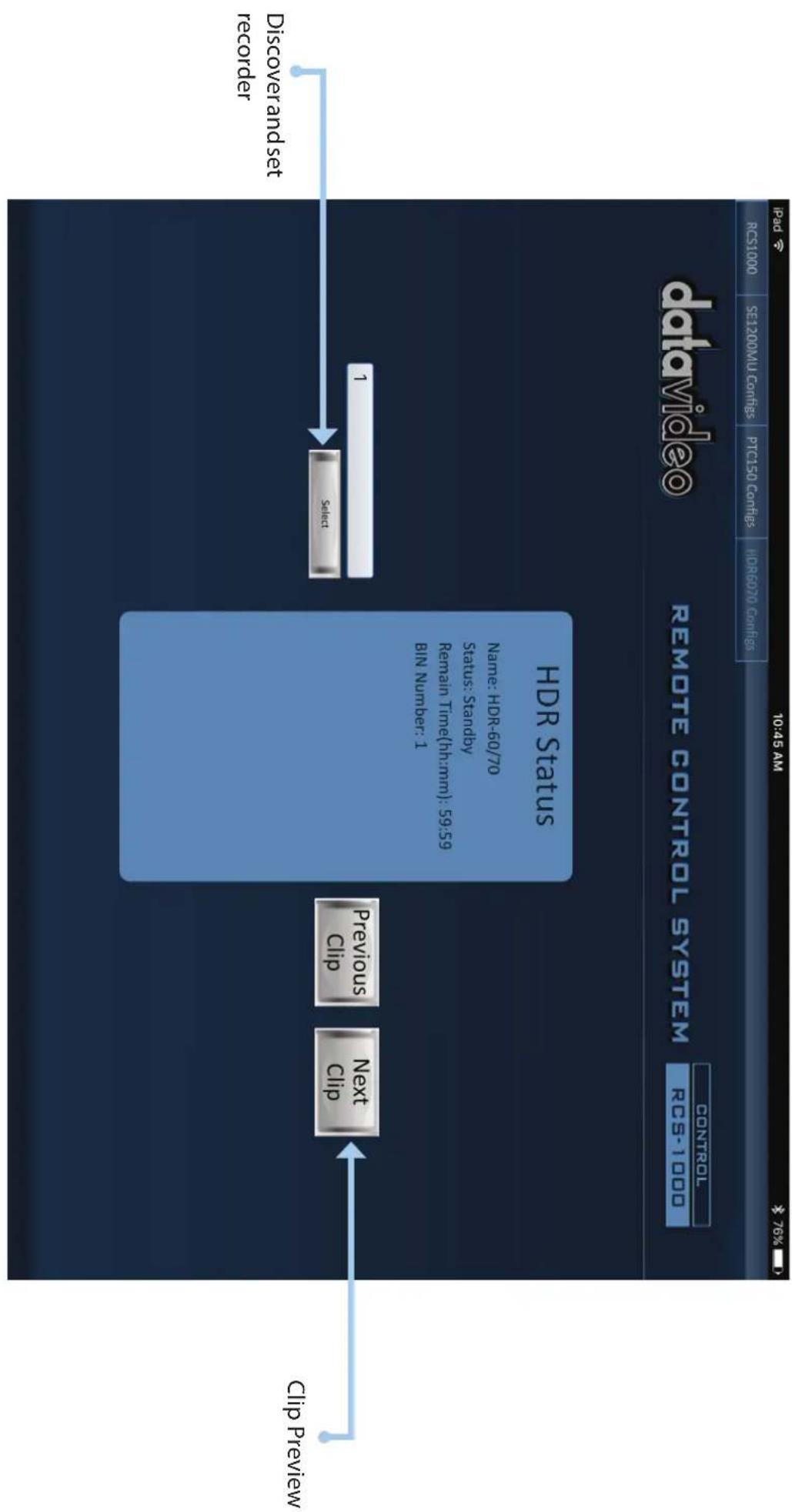
- Now that you have finished connecting all of the hardware we can provide an overview of each tab within the app. The tabs are divided into four sections: RCS1000, SE1200MU, PTC150 Configs, and HDR6070 Configs. The RCS1000 tab is the main window which provides complete control over your switcher, camera presets, and your recorder. The SE1200MU Configs tab allows you to access the individual switchersettings.(Formoreinformation, pleaserefertotheSE-1200MUmanual)ThePTC150 Configs tab is where you would setup and control your cameras. Lastly, the HDR6070 Configs tab is where you would control the HDR-60 or HDR-70 recorder clips.
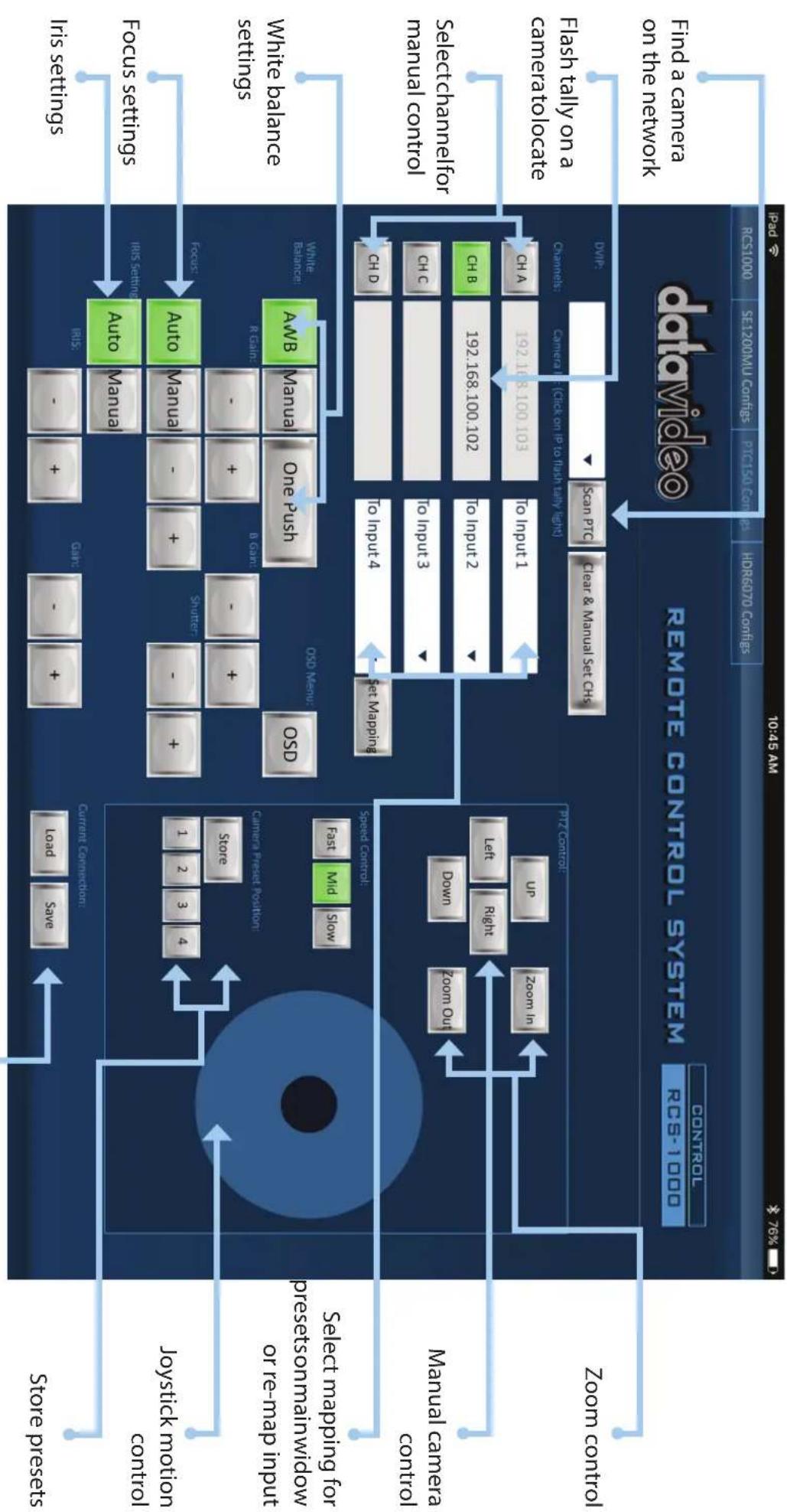
- Select the "PTC150Configs" tab to setup the camera presets. At the top of the interface, press the "Scan PTC" button to have the app link to the cameras. After you scan for the cameras, the IP address of each connected camera will appear in the channel boxes. In our example, there are just two cameras connected. To identify a camera press the IP address box to make the tally light flash on the camera. (Tap it again to cancel the Tally light flash)
- You can now set the mapping of each camera, which just means that you can set which preset each camera is linked with. So if I want camera B to be on Preset A then I can map it to input 1 via the drop down selector. Once I am finished, press the "Set Mapping" button to store it.
- The buttons in the lower left quadrant allows you to set basic camera exposure settings such as White Balance, Focus type, Iris, and gain. For more detailed information on the exposure settings please refer to your PTC-150(T) manual.
- ThePTZControlboxallowsyou to control individual camera positions, zoom, speed, and camera preset locations. To control a camera, press the camera Channel such as "CH A" and then you can test your controlmovementsandstorepresetsbypassingthe"Storebuttonandthenpressonthepresetnumber button.
- Atthebottomofthepage,youcansaveyourconnectionsettingsbypassingthe"Save"buttonunderthe Current Connection section.
- Now that you have the cameras setup you can proceed to the RCS1000 tab to begin running your system.
T-Bar for SE-1200MU
flowchart
graph TD
    A["Data Video Remote Control System"] --> B["PTC-150 Pressets (4 per camera)"]
    A --> C["HDR-70 Recorder"]
    A --> D["PIDP"]
    A --> E["PROGRAM"]
    A --> F["RESET"]
    A --> G["TRANSITION"]
    A --> H["Transitionselection for SE-1200MU"]
    A --> I["STE-1200MU Preview"]
    A --> J["STE-1200MU Program"]
    A --> K["STE-1200MU Transition selection for SE-1200MU"]
    A --> L["STE-1200MU RESET"]
    A --> M["STE-1200MU PROGAM"]
    A --> N["STE-1200MU PROGRAM"]
    A --> O["STE-1200MU PROVIEW"]
    A --> P["STE-1200MU RESET"]
    A --> Q["STE-1200MU PROGAM RESET"]
    A --> R["STE-1200MU PROVIEW RESET"]
    A --> S["STE-1200MU PROVIEW RESET"]
    A --> T["STE-1200MU PROVIEW RESET"]
    A --> U["STE-1200MU PROVIEW RESET"]
    A --> V["STE-1200MU PROVIEW RESET"]
    A --> W["STE-1200MU PROVIEW RESET"]
    A --> X["STE-1200MU PROVIEW RESET"]
    A --> Y["STE-1200MU PROVIEW RESET"]
    A --> Z["STE-1200MU PROVIEW RESET"]
    A --> AA["STE-1200MU PROVIEW RESET"]
    A --> AB["STE-1200MU PROVIEW RESET"]
    A --> AC["STE-1200MU PROVIEW RESET"]
    A --> AD["STE-1200MU PROVIEW RESET"]
    A --> AE["STE-1200MU PROVIEW RESET"]
    A --> AF["STE-1200MU PROVIEW RESET"]
    A --> AG["STE-1200MU PROVIEW RESET"]
    A --> AH["STE-1200MU PROVIEW RESET"]
    A --> AI["STE-1200MU PROVIEW RESET"]
    A --> AJ["STE-1200MU PROVIEW RESET"]
    A --> AK["STE-1200MU PROVIEW RESET"]
    A --> AL["STE-1200MU PROVIEW RESET"]
    A --> AM["STE-1200MU PROVIEW RESET"]
    A --> AN["STE-1200MU PROVIEW RESET"]
    A --> AO["STE-1200MU PROVIEW RESET"]
    A --> AP["STE-1200MU PROVIEW RESET"]
    A --> AQ["STE-1200MU PROVIEW RESET"]
    A --> AR["STE-1200MU PROVIEW RESET"]
    A --> AS["STE-1200MU PROVIEW RESET"]
    A --> AT["STE-1200MU PROVIEW RESET"]
    A --> AU["STE-1200MU PROVIEW RESET"]
Now you are ready to use the RCS-1000. Below is the main control panel for controlling the PTC-150 cameras, SE-1200MU switcher and HDR-70 recorder.
CONTROL
Save camera settings
flowchart
graph TD
    A["Store press"] --> B["Current Connection"]
    B --> C["load Save"]
    B --> D["+"]
    B --> E["-"]
    B --> F["+"]
    B --> G["+"]
    B --> H["+"]
    B --> I["+"]
    J["Store"] --> K["Storage"]
    K --> L["1 2 3 4"]
    L --> M["Auto Manual"]
    M --> N["Auto Manual"]
    N --> O["Auto Manual"]
    O --> P["Auto Manual"]
    P --> Q["Auto Manual"]
    Q --> R["A/B Manual"]
    R --> S["One Push"]
    S --> T["OSD Manual"]
    T --> U["OSD"]
    U --> V["A/B"]
    V --> W["White balance settings"]
    V --> X["Focus settings"]
    V --> Y["Iris settings"]
    V --> Z["White balance settings"]
    AA["Select mapping for prestesomainwidow or re-map input"] --> AB["Manual camera control"]
    AC["Select channelfor manual control"] --> AD["Ch C"]
    AD --> AE["Ch D"]
    AE --> AF["To Input 4"]
    AF --> AG["Set Mapping"]
    AG --> AH["Ch B 192.168.100.102"]
    AH --> AI["To Input 2"]
    AI --> AJ["To Input 3"]
    AJ --> AK["To Input 4"]
    AK --> AL["Ch D"]
    AL --> AM["To Input 3"]
    AM --> AN["To Input 2"]
    AN --> AO["To Input 1"]
    AO --> AP["Ch A 192.168.100.103"]
    AP --> AQ["To Input 1"]
    AQ --> AR["Ch B 192.168.100.102"]
    AR --> AS["To Input 2"]
    AS --> AT["To Input 3"]
    AT --> AU["To Input 4"]
    AU --> AV["Ch D"]
    AV --> AW["To Input 4"]
    AW --> AX["Ch B 192.168.100.102"]
    AX --> AY["To Input 2"]
    AY --> AZ["To Input 3"]
    AZ --> BA["To Input 4"]
    BA --> BB["Ch D"]
    BB --> BC["To Input 3"]
    BC --> BD["To Input 4"]
    BD --> BE["Ch B 192.168.100.102"]
    BE --> BF["To Input 2"]
    BF --> BG["To Input 3"]
    BG --> BH["To Input 4"]
    BH --> BI["Ch B 192.168.100.102"]
    BI --> BJ["To Input 2"]
    BJ --> BK["To Input 3"]
    BK --> BL["To Input 4"]
    BL --> BM["Ch A 192.168.100.103"]
    BM --> BN["To Input 1"]
    BN --> BO["Ch A 192.168.100.103"]
    BO --> BP["To Input 2"]
    BP --> BQ["Ch A 192.168.100.103"]
    BQ --> BR["To Input 3"]
    BR --> BS["To Input 4"]
    BS --> BT["Ch A 192.168.100.103"]
    BT --> BU["To Input 2"]
    BU --> BV["Ch B 192.168.100.102"]
    BV --> BW["To Input 3"]
    BW --> BX["To Input 4"]
    BX --> BY["Ch B 192.168.100.102"]
    AB --> BY
    AC --> BY
    AD --> BY
    AE --> BY
    AF --> BY
    AG --> BY
    AH --> BY
    AI --> BY
    AJ --> BY
    AK --> BY
    AL --> BY
    AM --> BY
    AN --> BY
    AO --> BY
    AP --> BY
    AQ --> BY
    AR --> BY
    AS --> BY
    AT --> BY
    AU --> BY
    AV --> BY
    AW --> BY
Below is the window to control up to 4 PTC-150 cameras.
CONTROL
flowchart
graph LR
    A["Clip Preview"] --> B["Next Ctrl"]
    B --> C["Previous Ctrl"]
    C --> D["1"]
    D --> E["Serial"]
    E --> F["Discover and set recorder"]
    G["Remote Control System RCS-1.000 CONTROL"] --> H["DataVideo"]
    I["10:45 AM"] --> J["PSD"]
    K["76%"] --> L["RCS1000 SE1200ML Controls PTC150 Controls HRB070 Controls"]
Below is the window to control the recording of your production.
CONTROL
datavideo
www.datavideo.com
Datavideo Hong Kong Ltd
G/F..26 Cross Lane
Wanchai, Hong Kong
Tel: +852-2833-1981
Fax:+852-2833-9916
2nd Floor- North Wing, Govardhan Building, Opp. NCC Group Headquarters, Chittoor Road,
Cochin-682035
Tel: +91 4844-025336
Fax:+91 4844-047696
E-mail: sales@datavideo.in
Netherlands
Datavideo Technologies Europe BV
Floridadreef 106
3565 AM Utrecht,
The Netherlands
Tel: +31-30-261-96-56
Fax:+31-30-261-96-57
E-mail:info@datavideo.nl
Singapore
Datavideo Technologies (S) PTE Ltd
No. 178 Paya Lebar Road #06-03
Singapore 409030
Tel: +65-6749 6866
Fax:+65-6749 3266
E-mail:sales@datavideo.sg
Singapore Taiwa
Datavideo Visual Technology(S) Pte Ltd
No. 178 Paya Lebar Road #06-07
Singapore 409030
Tel: +65-6749 6866
Fax:+65-6749 3266
E-mail:info@datavideovirtualset.com
nited States Uni
Datavideo Technologies Co. Ltd
18F.-2, No.176, Jian 1st Rd., Zhonghe Dist., New Taipei City 235, Taiwan, R.O.C.
Tel: +886-2-8227-2888
Fax:+886-2-8227-2777
The image is too blurry to recognize any text content.
Datavideo UK Limited
Units1 & 2 Waterside Business Park Hadfield, Glossop, Derbyshire
SK13 1BE, UK
Tel: +44-1457 851 000
Fax:+44-1457 850 964
E-mail:sales@datavideo.co.uk
France
Datavideo France s.a.r.l.
- datavideo
- RCS-1000
- INTRODUCTION
- CONNECT
- CONTROL
- www.datavideo.com
- Datavideo Hong Kong Ltd
- Netherlands
- Datavideo Technologies Europe BV
- Singapore
- Datavideo Technologies (S) PTE Ltd
- Singapore Taiwa
- Datavideo Visual Technology(S) Pte Ltd
- nited States Uni
- Datavideo Technologies Co. Ltd
- The image is too blurry to recognize any text content.
- Datavideo UK Limited
- France
- Datavideo France s.a.r.l.
Brand : DataVideo
Model : RCS-1000
Category : Controller