
PLMRCAP50 - Car audio accessory Pyle - Free user manual and instructions
Find the device manual for free PLMRCAP50 Pyle in PDF.


| Product Type | Digital Power Capacitor |
| Capacitance | 0.5 Farad (±5%) |
| Voltage Rating | DC 12 - 24V |
| Surge Voltage | 20 - 24 Volts |
| Operating Temperature | Up to 105°C / 221°F |
| Display Type | Blue Digital Display |
| Housing Material | ABS with Brushed Aluminum Interior |
| Terminal Material | Chrome Plated Posts |
| Protection Circuits | Electronic Polarity Protection, Over Voltage Protection |
| Installation Hardware Included | Mounting and Charging Hardware |
| Product Dimensions (W x L) | 3.74 x 10.24 inches |
| Recommended Wire Gauge | 8 AWG or 10 AWG OFC for power; 18-20 AWG for remote |
| Fuse Requirement | No fuse between capacitor and amplifier; fuse at battery required |
| Power-Up Indication | Status LED and flickering decimal point during charging |
| Auto Shut-Off | After 1 minute if no voltage fluctuation exceeds ±0.1A |
| Safety Feature | Reverse polarity protection with buzzer warning |
Frequently Asked Questions - PLMRCAP50 Pyle
User questions about PLMRCAP50 Pyle
0 question about this device. Answer the ones you know or ask your own.
Ask a new question about this device
Download the instructions for your Car audio accessory in PDF format for free! Find your manual PLMRCAP50 - Pyle and take your electronic device back in hand. On this page are published all the documents necessary for the use of your device. PLMRCAP50 by Pyle.
USER MANUAL PLMRCAP50 Pyle
Questions? Comments?
We are here to help!
Phone:(1)718-535-1800
Email: support@pyleusa.com
PYLE
HYDRA
natural_image
Exterior view of a modern office building (no signage)PLMRCAP50
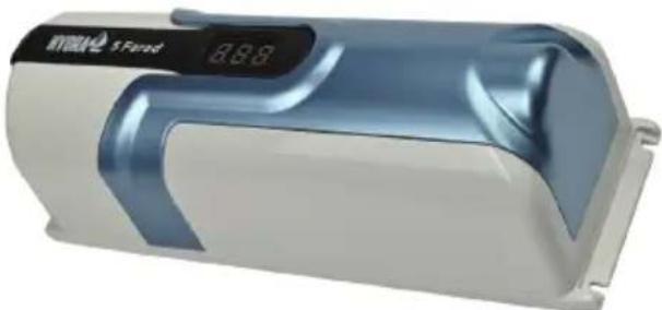
0.5 Farad Digital Power Capacitor
High-Performance Car Audio Accessory with Blue Digital Display and Stainless-Steel Screws
USER GUIDE
PLEASE READ THIS USER MANUAL COMPLETELY BEFORE OPERATING THIS UNIT AND RETAIN THIS BOOKLET FOR FUTURE REFERENCE.
WARNING:
- This power capacitor may explode and cause serious injury or death if abused or connected improperly.
- Refer to the Installation manual for correct procedures when making connections, and or charging/discharging the capacitor.
- Do not expose the capacitor to voltages higher than specified et any time.
- Do not install in direct sunlight or extreme temperatures.
CAUTION:
Improper connection of this product can cause electrical damage to the vehicle and/or equipment. PyleUSA assumes no responsibility for any damages that could occur due to improper connection of this product.
TABLE OF CONTENTS
| Introduction | 3 |
| Operation | 3 |
| Installation | 4 |
| Power-Up Procedures and Display Function | 6 |
| Features and Technical Specs | 7 |
Introduction
The manual provides detailed informations for function, installation and operation of the power capacitor.
To avoid possible injury and damage to your audio system, please study the manual carefully before you start the power capacitor installation.
Operation
The digital display capacitor is an energy storage device, it is designed to supplement audio amplifiers power supply during high current demand. An example of such a demand is when music hits a low bass transient.
The overall bass response of an audio system will be enhanced by using this device. It is capable of storing a large amount of energy which can be discharged very fast when needed.
This makes the power cap a logical addition to the audio system as automotive batteries are not designed to deliver the current required in high power car audio installations.
Another feature of the digital display capacitor is its availability to filter car AC voltage induced by the amplifier's power supply.
This can otherwise cause audible noise in the sound system of the car.
Installation
For maximum performance, the digital power capacitor should be installed as close to your amplifier as possible. The ideal location is one that allows short wiring runs while keeping the capacitor some what isolated from the heat created by the amplifier system. The positive power wire should be kept as short as possible and should be connected to the amplifier's battery supply cable. We recommend that a High-Performance Distribution block should be used to create a splice into this cable (as image shown).
No fuses should be installed in the wire between the power capacitor and the amplifier system, but make sure, that there is an appropriate fuse at the battery in the main supply cable. The ground cable for the power capacitor should be kept as short as possible and should be connected directly to the vehicle's chassis at a bare metal surface. Do not ground the capacitor directly to the amplifier ground terminal or ground cable (see fig.1).
The positive and the negative wires to the capacitor should have the same gauge as the amplifier power wires. High Performance 8 or 10AWG OFC power cables are a good choice for this application. If the digital display has remote terminal, remember to connect it with the remote terminal of your amplifier(s) using 18 to 20 AWG primary wire. (See fig.2)
REM (ON/OFF) = REMOTE CONTROL
Connect the Rem terminal to the automatic antenna connector of your car radio. Now when turning on and off your car radio, the amplifier automatically switches on and off. A cable diameter of 0.5mm2 is sufficient.

Power-Up Procedures and Display Functions
- Connect the power cable to the digital power capacitor. Connect the ground cable first and second the positive cable.
- The digital pcb system will turn on automatically at first charging process. Then, the status led will light and the decimal point display will flicker, to indicate the system is charging the capacitor.
- When the capacitor has been fully charged, the decimal point display will not flicker and you will see the display shows the DC voltage of the car electronic system.
- If the DC voltage of the car electronic system exceeds over +1-0, 1 ampere, the digital pcb will automatically operate (ex. the car audio system hits the bass or use some other high consumed electronic equipment, which cause large voltage drops).
- If the DC voltage of the car does not exceed over +1-0, 1 ampere, the digital pcb will keep one original "ON" status for one minute to assure the car electronic system is stable. The digital pcb will automatically turn off and stay in "stand-by" mode.
- If the DC voltage of the car electronic system exceeds over +1-0,1ampere, the capacitor will automatically operate again.
Safety Protection Function
If the user accidentally reverses the polarity of (+) and (-), it can cause damage to the system and also be harmful for the user. Therefore, we have designed the pcb relay inside which protects wrong connection and the unit will not turn on and the buzzer will warn. The digital power capacitor will only turn on if all wiring is connected correctly as per instruction.
Features:
• 0.5 Farad Digital Display Power Capacitor
- Capacitance ± 5%. 20-24 Volt Surge, 105°C/221°F
- Blue Digital Display
• Strong Finishing For A Better Installation Result
• Chrome Plated Post Kits
• Electronic Polarity Protection Circuit
• Over Voltage Protection Circuit
• Includes Mounting Charging Hardware
• ABS housing and Aluminum Brushed Inside
What's in the Box:
• Digital Power Capacitor
- Mounting Charging Hardware
Technical Specs:
• Power Output: DC 12-24V
• Construction Materials: ABS
• Product Dimensions: 3.74" x 10.24"-inches
- HYDRA
- PLMRCAP50
- Farad Digital Power Capacitor
- PLEASE READ THIS USER MANUAL COMPLETELY BEFORE OPERATING THIS UNIT AND RETAIN THIS BOOKLET FOR FUTURE REFERENCE.
- WARNING:
- CAUTION:
- Introduction
- Operation
- Installation
- REM (ON/OFF) = REMOTE CONTROL
- Power-Up Procedures and Display Functions
- Safety Protection Function
- Features:
- What's in the Box:
- Technical Specs:
Brand : Pyle
Model : PLMRCAP50
Category : Car audio accessory