
Pro CE-G15TPF - Grill plate Cecilware - Free user manual and instructions
Find the device manual for free Pro CE-G15TPF Cecilware in PDF.


| Brand | Cecilware |
| Model | Pro CE-G15TPF |
| Product Type | Thermostatic Gas Griddle |
| Category | Grill plate |
| Griddle Width | 15 inches (381 mm) |
| Power Source | Natural Gas or Propane (LP) with conversion kit |
| Ignition | Piezo igniter with individual standing pilots |
| Thermostatic Control | Yes, with temperature settings per burner |
| Flame Failure Protection | Yes, shuts off gas if flame lost |
| Griddle Surface Material | Stainless steel (chromed or stainless) |
| Grease Tray | Removable, accessible from front |
| Legs | Adjustable height, leveling feet |
| Clearances (from non-combustible surfaces) | 6" sides, 6" rear, 4" countertop |
| Installation Surface | Non-combustible only |
| Gas Connection | Manual shut-off valve required (3/4" NPT typical) |
| Safety Features | Gas leak procedures, safety shut-off, warning labels |
| Cleaning | Daily griddle stone, weekly deep cleaning with mild detergent |
| Maintenance | Qualified personnel only, valve lubrication, burner cleaning |
| Warranty | Grindmaster-Cecilware industry best warranty, see gmcw.com |
| Compliance | ANSI Z223.1, CSA B149.1, NFPA 96 |
| Parts Included | Main burner, pilot burner, regulator, grease tray, legs, orifices for LP conversion |
Frequently Asked Questions - Pro CE-G15TPF Cecilware
User questions about Pro CE-G15TPF Cecilware
0 question about this device. Answer the ones you know or ask your own.
Ask a new question about this device
Download the instructions for your Grill plate in PDF format for free! Find your manual Pro CE-G15TPF - Cecilware and take your electronic device back in hand. On this page are published all the documents necessary for the use of your device. Pro CE-G15TPF by Cecilware.
USER MANUAL Pro CE-G15TPF Cecilware
Thermostatic Gas Griddle
CE-G15TPF, CE-G24TPF, CE-G36TPF, CE-G48TPF

natural_image
Exterior view of a stainless steel laboratory gas grater with control knobs (no text or symbols visible)Model: CE-G24TPF

Intertek

Intertek
Table of Contents
| Safety Information | 2 |
| Specifications | 3 |
| Installation | 4 |
| Adjustments | 6 |
| Lighting Instructions (Thermostat Control) | 6 |
| Preparing Griddle | 6 |
Operation 6
Cleaning....7
Maintenance ....7
Troubleshooting......8
Parts Diagram and List....8
Thank you for purchasing this quality Gas Griddle. For your safety and the safety of others, read all warnings and the operator's manual before installing or using the product. Properly instruct all operators. Keep training records. For future reference, record serial number here:
Safety Information
Important Safety Information

This is the safety alert symbol. It is used to alert you to potential personal injury hazards. Obey all safety messages that follow this symbol to avoid possible injury or death.
For your safety and the safety of others, read all warnings and the operator manual before installing or using the product.
DANGER: This term warns the user of imminent hazard that will result in serious injury or death.
WARNING: This term refers to a potential hazard or unsafe practice, which could result in serious injury or death.
CAUTION: This term refers to a potential hazard or unsafe practice, which could result in minor or moderate injury.
NOTICE: This term refers to information that needs special attention or must be fully understood.
WARNING
Improper installation, adjustment, alteration, service, or maintenance can cause property damage, injury, or death. Read the installation, operating, and maintenance instructions thoroughly before installing or servicing this equipment.
Do not store or use gasoline or other flammable vapors or liquids in the vicinity of this or any other appliance.
You must post instructions in a prominent location to be followed in the event the user smells gas. This information shall be obtained by consulting the local gas supplier.
If you smell gas, close the shut-off valve, open windows, ventilate, and evacuate the area immediately. Do not touch electrical switches or plugs. Extinguish any open flames. Immediately call your gas supplier.
Unit should only be used in a flat, level position.
Failure to install, adjust, or maintain this equipment properly can result in injury or death.
Improper installation, adjustment, alteration, service, or maintenance can cause property damage, injury, or death. This installation must conform with local codes, with the National Fuel Gas Code, ANSI Z223.1 (latest edition), Natural Gas Installation Code, CAN/CGA - B149.1, or the Propane Installation Code, CAN/CGA - B149.2 as applicable. Have this equipment installed and adjusted by a qualified technician in accordance with federal, state, and local codes.
Do not place anything over the flue opening.
Do not place combustibles or non-combustible material in the vicinity of the unit as this could cause fires or obstruct air flow to the burner(s).
The unit must be disconnected from the gas supply during pressure testing of pipelines in excess of 1/2 psig and isolated, by turning of the manual gas shut-off valve, during any testing equal to or less than 1/2 psig.
A qualified service technician must handle all maintenance and repair.
FAILURE TO COMPLY WITH THE ABOVE RISKS PERSONAL INJURY, SHOCK HAZARD, FIRE, OR DAMAGE TO EQUIPMENT.
CAUTION
Read and understand the operating instructions in this manual thoroughly. Only allow properly trained persons to operate this machine.
Stay alert at all times during operation.
This unit must be installed under a ventilation hood.
Allow unit to cool before cleaning or moving.
Do not leave appliance unattended with main gas valve open.
Do not use an open flame to check for leaks. Check all gas piping for leaks with a soap and water solution before operating unit.
Safety Information (continued)
NOTICE
These models are designed, built, and sold for commercial use only.
Keep operating area clean.
Before using this equipment, it must be cleaned thoroughly. Failure to clean surfaces before using the unit could cause food contamination and excessive smoking. Clean all surfaces before use.
Do not spray controls or outside of unit with liquids or cleaning agents.
Smoke appearing on initial use of the appliance is normal. This is a result of the rust-preventing coating burning off. Allow the unit to "burn in" for at least 30 minutes before first use.
Specifications
This unit is intended to be used to as a cooking appliance in commercial foodservice operations only. It is not intended for household use.
If you have questions concerning the installation, operation, maintenance or service of this product, contact your authorized service agent.
THESE UNITS ARE SUITABLE FOR INSTALLATION ON NON-COMBUSTIBLE SURFACES ONLY.
Noncombustible and unit clearances: 6" sides (152 mm)
6" rear (152 mm) 4" countertop (102 mm)
There must be adequate clearance for removal of the front panel. All major parts except the burners are removable through the front if the gas line is disconnected.
Do not obstruct the flow of combustion and ventilation air, under the unit near the legs or behind the unit near the flue. The space between the legs at the bottom admits combustion air. DO NOT BLOCK THIS SPACE. Do not place objects between the bottom of the unit and the counter top.
If equipped, the vent line from the gas appliance pressure regulator shall be installed to the outdoors in accordance with local codes or, in the absence of local codes, with the National Fuel Gas Code, ANSI Z223.1/NFPA 54, or the Natural Gas and Propane Installation Code, CSA B149.1, as applicable.
Installation must conform with local codes, or in the absence of local codes, with the National Fuel Gas Code, ANSI Z223.1/NFPA 54, Liquefied Petroleum Gas Code ANSI/NFPA 58, CSA-B149.1, or the Propane Installation Code, CSA-B149.2 as applicable and in accordance with local codes.
- The appliance and its individual shutoff valve (to be supplied by user) must be disconnected from the gas supply piping system during any pressure testing of that system at test pressures in excess of 12 psi (3.5 kPa).
- The appliance must be isolated from the gas
supply piping system by closing its individual manual shut-off valve during any pressure testing of the gas supply piping system at test pressures equal to or less than 12 psi (3.5 kPa).
Do not permit fans to blow directly at the unit. Wherever possible, avoid open windows next to the units' sides or back. Avoid wall type fans, which create air crosscurrents within a room.
It is also necessary that sufficient air should be allowed to enter the room to compensate for air removed by any ventilating system. Otherwise, an abnormal atmospheric pressure will occur, affecting operation and causing undesirable working conditions.
A properly designed and installed hood will act as the ventilating system for the room or area in which the unit is installed. For more information about air flow and venting, please read NFPA 96: Standard for Ventilation Control and Fire Protection of Commercial Cooking Operations
Installation
Unpacking
Carefully lift unit out of shipping container, and inspect immediately for shipping damage. Your gas griddle was shipped in a carton designed to give it maximum protection. It was thoroughly inspected before leaving the factory. File any claims for shipping damage or irregularities directly with the carrier.
⚠ WARNING: Do not store combustible materials on top or under any griddle.
⚠ WARNING: Do not use an open flame to test for leaks. Check all gas piping for leaks with a soap and water solution before operating unit.
▲ NOTICEUnit must only be installed and operated with legs provided by manufacturer.
The installer must include a manual valve to shut off the fuel supply into the appliance.
Pipe thread sealing compound must be resistant to the action of liquefied petroleum gases.
Verify that the product regulator and orifice match gas type (natural gas or LP-propane).
Adjust pilot if necessary.
Adjust main burner(s) if necessary.
Adjust main burner air shutter if necessary (if equipped).
Component Assembly
Legs are shipped with unit in a plastic bag. To install the legs, tilt back and screw the two front legs into the permanently fastened nuts at the corners. Mount the rear legs by tilting unit forward.
Level unit after final installation. Height may be adjusted by turning the feet up or down as desired. Do not slide unit with legs mounted; lift to move the unit.
Clearances
THESE UNITS ARE SUITABLE FOR INSTALLATION ON NON-COMBUSTIBLE SURFACES ONLY.
Distance required between unit and non-combustible material: 6" sides, 6" rear, and 4" countertop.
Air Supply and Ventilation
Adequate ventilation and air supply must be provided in order for the griddle to operate properly and efficiently. The area in front and above the griddle must be clear to avoid any obstruction of flow of combustion and ventilation air. Do not connect the griddle flue directly to a building exhaust system or place the flue directly into the plenum of an exhaust hood as it will adversely affect the gas combustion of the unit.
Gas Connection
An accessible manual shut-off valve must be installed in gas supply line ahead of the unit. The size of the supply pipe must be sized to accommodate all of the gas-fired equipment that may be connected to the gas supply. Check with your local gas company as to the proper size. Only pipe sealant resistant to the action of LP gas should be used on pipe joint. Before attempting to light the griddle, check all joints for leaks using a soap and water solution.
Units are shipped from the factory equipped for use with natural gas. A conversion kit is included.
Conversion from Natural Gas to Propane
If conversion to propane (LP) is desired, the conversion should be completed before connecting the unit to the gas supply.
▲ CAUTION: Ensure that the appliance is isolated from the gas supply before commencing servicing.
▲ CAUTION: These conversions should only be carried out by qualified persons. All connections must be checked for leaks before re-commissioning the appliance.
Orifices necessary for propane are provided in a bag tied to the valve on the front panel.
- Turn "off" the gas supply at the main supply.
- Remove the burner from top of the gas pipe, taking care not to damage the thermocouples, if unit is equipped.
Adjustment of components that have adjustments/ settings sealed (e.g. paint sealed) can only be adjusted in accordance with the following instructions and shall be re-sealed before operating this appliance.
Pilot Burner Orifice
- To remove the pilot burner injector, loosen the gas supply tube at the gas control unit end of the supply tube to allow the tube to be moved easily without bending.
- Disconnect the gas supply tube from the base of the pilot burner and withdraw the pilot injector from inside the pilot burner.
- Determine the correct injector size for the corresponding gas from the rating label.
- Re-connect the supply tube to the base of the pilot burner and tighten the gas supply tube at the gas control unit end.
- Replace the front control panel and tighten the 4 screws on the front to secure the panel in place.
- Refit the control knobs to the front control panel. The control knobs are a push fit onto the shafts of the gas control valves.
Installation (continued)
Pilot Burner Orifice (continued)
Pilot Orifice

Pilot Orifice gas supply tube
Main Burner Orifice

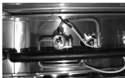
- Remove the knobs and front panel.
natural_image
Interior view of a stainless steel industrial equipment enclosure with pipes and valves (no visible text or symbols)- Unscrew bolts and pilot valve and then remove the manifold.

natural_image
Metal mechanical component with hexagonal base and central shaft (no visible text or symbols)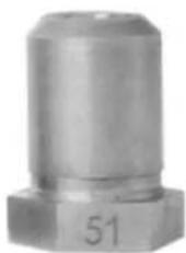
natural_image
Metal mechanical component with hexagonal base and central shaft (no visible text or symbols)- Note number on side of valve orifice fittings. #41=NAT; #51=LP. Swap fittings.

natural_image
Close-up of a metallic electrical component with mounting holes and a central hole (no visible text or symbols)- Unscrew hexagonal cap on top of regulator
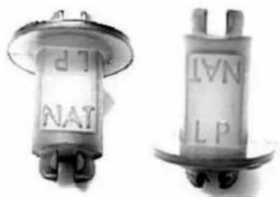
- Remove plastic insert, flip over and snap back into place.

natural_image
Close-up of a metallic mechanical component with a cylindrical top and hexagonal base (no visible text or symbols)- LP position of insert. Replace hexagonal cap and tighten.
Adjustments
Main Burner Air Supply
- A proper balance of gas volume and primary air supply must be maintained which will result in complete combustion. Insufficient air supply results in a yellow tipped flame. Primary air supply is controlled by an air shutter on the front of the burner.
- Loosen the screws on the front of the burner and increase the opening of the air shutter to eliminate the yellow tips of the burner flame. Lock the air shutter in place by tightening the screws.
Lighting Instructions (Thermostat Control)
⚠️ CAUTION: All burners are lit from burning pilots. Turn the control knob to the desired temperature.
All burners have individual standing pilots which allows the main burners to cycle 'ON' - 'OFF' without the need to manually ignite the burner.
Flame failure protection is incorporated for each burner which will shut off the gas supply to that burner if flame is lost.
- Select the burner required, depress the gas control knob, and rotate counterclockwise to the 'pilot' position.
- With the gas control knob held in the depressed position, press the piezo igniter button to ignite the pilot burner.
- Hold in the gas control knob for approximately 10-15 seconds, then release. The pilot burner should remain lit. (If not, repeat steps 1 to 3 above after waiting for 5 minutes.)
- Rotate the gas control knob counterclockwise to the desired temperature mark.
- The main burner will ignite automatically.
- Turn the main burner off: Turn the gas control knob clockwise to the "pilot" position. The main burner will extinguish and the pilot burner will remain alight.
- Turn all the burners off: Turn the gas control knob fully clockwise to the '•' position. The main burner and the pilot burner will extinguish.
- Wait 5 minutes before relighting.
Preparing Griddle
Initial Cleaning
The griddle surface is protected with a protective coating. To remove this coating, light the burners and wait approximately 5 minutes for the griddle to heat up, wet the entire griddle surface with clear water, and add some griddle cleaner to the water. Let the cleaner work a few minutes, then wipe the cooking surface dry.
Seasoning
Heat to low temperature (300°F - 350 °F/150°C - 180°C) and pour on a small amount of cooking oil, about one ounce (30cc) per square foot of surface. Spread the oil over the entire griddle surface with a cloth to create a thin film. Wipe off any excess oil with a cloth. Repeat this procedure 2 to 3 times until the griddle has a slick, mirror-like surface.
Operation
Turn the burners on about 15-20 minutes before cooking for preheating. Set the knobs to the desired temperature. Each valve will control the gas flow to the burner to bring that area of the unit up to the set temperature. If different temperature settings are to be used, adjoining areas should be set at progressively higher temperatures using the lowest temperatures on the outside burners. A uniform and systematic approach to the loading of the unit will produce the most consistent product results.
Cleaning
Note: Use only non-abrasive cleaners. Abrasive cleaners scratch the finish of your unit, marring its appearance and making it susceptible to dirt accumulation. Do not use steel wool, other abrasive cleaners or cleaners/sanitizers containing chlorine, iodine, ammonia or bromine chemicals as these will deteriorate the material and shorten the life of the unit. If the stainless steel surfaces become discolored, scrub by rubbing only in the direction of the finished grain.
Daily Cleaning:
- Always turn unit off and allow it to cool completely before cleaning.
- Clean the griddle surface thoroughly. If necessary, use a griddle stone.
- After cleaning griddle surface, coat with cooking oil to prevent rusting.
- Remove the grease pan, empty it and wash it with a mild detergent.
- Clean stainless steel or chromed surfaces with a damp cloth and polish with a soft, dry cloth.
- Once a day, thoroughly clean backsplash, sides, and front.
Weekly Cleaning
- Clean unit thoroughly. Clean stainless steel or chromed surfaces with a damp cloth and polish with a soft, dry cloth. A mild detergent may be used. To remove discolorations, use a non-abrasive cleaner.
- To remove the drip pan, pull by handle through the opening in the front panel.
- Burner air shutter openings must be kept clean. Main burner ports must be kept clean. Clean burners with a stiff brush.
- After each "weekly" cleaning, the griddle must be seasoned again. If the griddle usage is very high, the "weekly" cleaning procedures may be done more often than once a week.
Air shutters should be cleaned of lint and dirt periodically.
Contact Grindmaster-Cecilware if major repairs or maintenance is required.
Maintenance
Qualified Service Personnel Only
Note: Only for qualified personnel specializing in Hotel and Restaurant Cooking Equipment. Factory approval required prior to any warranty repairs.
All valves must be checked and lubricated periodically. This must be done by an authorized service representative in your area.
After long periods of usage, burners and pilots should be cleaned for proper ignition and burner flame efficiency.
- Shut off all gas to the broiler griddle.
- Remove griddle plate and baffles.
- Lift burners from hanger brackets and off burner valves.
- Wire brush and clean burners, nichrome mesh and venturi of carbon deposits.
- Lubricate gas valves with high temperature valve grease.
- Replace burners and assemble parts in reverse order of removal.
- Follow lighting instructions, light and adjust flames for proper combustion and burner efficiency.
Troubleshooting
Before you call for help, please read the following:
| PROBLEM POSSIBLE CAUSE |
| Pilot burner can not be lit. • The pilot valve is obstructed.Pilot gas turned off pilot valve.The pilot valve is bad. |
| Fat appears to smoke excessively. • Griddle plate is too hot.Moisture in the food may be turning into steam. |
| Food sticks to griddle. • Griddle plate is too hot.Griddle surface needs cleaning and/or seasoning.Surface under food may not have been covered with enough oil. |
| Food burned around edges or contains dark specks. • Griddle plate is too hot.Griddle surface needs cleaning and/or seasoning.Surface under food may not have been covered with enough oil. |
| Food is undercooked inside. • Griddle plate is too hot.Food may not have been cooked for long enough time. |
| Food tastes greasy or has objectionable off-flavor. • Griddle plate is too hot.Food may have been stored improperly before cooking.Too much griddle oil used. |
| Noticeable build-up of gum on griddle. • Griddle plate is too hot.Griddle surface needs cleaning and/or seasoning.Too much griddle oil used. |
If you still need help, call Grindmaster-Cecilware Technical Service Department, (502) 425-4776 or (800) 695-4500 (USA & Canada only) (Monday through Friday 8 AM - 6 PM EST). Please have the model and serial number ready so that accurate information can be given.
Prior authorization must be obtained from Grindmaster-Cecilware for all warranty claims.
Grindmaster-Cecilware provides the industry's BEST warranty. Visit our website at GMCW.com for warranty terms and conditions.
Parts Diagram and List

Grindmaster-Cecilware
4003 Collins Lane, Louisville, KY 40245 USA
Phone: 502.425.4776 Toll Free: 800.695.4500
Fax: 502.425.4664
Web: gmcw.com Email: info@gmcw.com
| 1 Main Burner 410-00373 | |
| 2 Regulator 410-00226 | |
| 3 Pilot Burner Assembly (without orifice) 410-00335 | |
| 4 Pilot Orifice 0.45(NAT) | 410-00326 |
| 4 Pilot Orifice 0.25(LP) | 410-00327 |
| 5 Grease Tray | 410-00328 |
| 6 Adjustable Legs | 410-00227 |
| 7 Thermostat valve | 410-00329 |
| 8 Main Burner Fuel Tube Assembly | 410-00330 |
| 9 Orifice Holder Main Burner | 410-00331 |
| 10 Pilot Fuel Tube Assembly | 410-00332 |
| 11 Main Burner Orifice #41 NAT | 410-00261 |
| Main Burner Orifice #51 LP | 410-00262 |
| 12 Control Knob | 410-00333 |
| 13 Piezo Igniter | 410-00334 |
| 14 Cecilware Emblem | 410-00325 |
Grindmaster-Cecilware provides the industry's BEST warranty. Visit gmcw.com for warranty terms and conditions.

Grindmaster Cecilware
- Thermostatic Gas Griddle
- Safety Information
- Important Safety Information
- WARNING
- CAUTION
- Safety Information (continued)
- NOTICE
- Specifications
- THESE UNITS ARE SUITABLE FOR INSTALLATION ON NON-COMBUSTIBLE SURFACES ONLY.
- Installation
- Unpacking
- Component Assembly
- Clearances
- Air Supply and Ventilation
- Gas Connection
- Conversion from Natural Gas to Propane
- Pilot Burner Orifice
- Installation (continued)
- Adjustments
- Main Burner Air Supply
- Lighting Instructions (Thermostat Control)
- Preparing Griddle
- Initial Cleaning
- Seasoning
- Operation
- Cleaning
- Daily Cleaning:
- Weekly Cleaning
- Maintenance
- Qualified Service Personnel Only
- Troubleshooting
- Grindmaster-Cecilware
Brand : Cecilware
Model : Pro CE-G15TPF
Category : Grill plate