
VLT7 - Video camera Speco Technologies - Free user manual and instructions
Find the device manual for free VLT7 Speco Technologies in PDF.


| Type | Video Camera |
| Brand | Speco Technologies |
| Model | VLT7 |
| Resolution | 1080p (1920 x 1080) |
| Lens | 2.8mm fixed |
| Night Vision | IR LEDs, up to 30m |
| Weatherproof Rating | IP66 |
| Power Supply | DC 12V or PoE (802.3af) |
| Power Consumption | Max 5W |
| Dimensions (W x H x D) | 100mm x 70mm x 60mm |
| Weight | 0.5 kg |
| Mounting | Wall or ceiling mount |
| Video Output | H.264 / H.265 |
| Field of View | 100° diagonal |
| Storage | MicroSD card (up to 128GB) / NVR |
| Audio | Built-in microphone |
| Security | Password protection, HTTPS, firmware updates |
| Maintenance | Clean lens with soft cloth; avoid harsh chemicals |
| Repairability | Contact Speco support for spare parts |
Frequently Asked Questions - VLT7 Speco Technologies
User questions about VLT7 Speco Technologies
0 question about this device. Answer the ones you know or ask your own.
Ask a new question about this device
Download the instructions for your Video camera in PDF format for free! Find your manual VLT7 - Speco Technologies and take your electronic device back in hand. On this page are published all the documents necessary for the use of your device. VLT7 by Speco Technologies.
USER MANUAL VLT7 Speco Technologies
natural_image
Collection of white surveillance cameras with multiple lenses and mounting flanges (no visible text or symbols)VLB5 /VLB6/VLD5/VLD6M/VLT7
USER MANUAL
Thank you for purchasing our product. Speco Technologies is constantly developing and improving products. We reserve the right to modify product design and specifications without notice and without incurring any obligation.
Warnings
■ If the product does not work properly, please contact the dealer or where the product was purchased. Speco Technologies is not responsible for any problems caused by improper operation or repair.
■ Do not expose the unit to heavy stress, violent vibration or long-term exposure to water and humidity during transportation, storage, and/or installation.
■ Do not install near sources of heat.
■ Only install the product in environments inside the specification operating temperature and humidity range.
■ Do not install the camera near power lines, radar equipment or other electromagnetic radiation.
■ Do not block any ventilation openings if any.
■ Use all the weatherproofing hardware requirement to minimize weather intrusion.
Introduction
This camera series is the latest technology and advanced circuit design, which features high definition and sensitivity, low noise and distortion and supports HD video transmission with the common coaxial cable, ensuring the requirement of the HD monitoring in the traditional surveillance system.
● High Resolution
Adopt high performance sensor, providing high definition and clear image.
● High Transmission Performance
Real-time transmission with high speed and long distance.
● DNR
Reduce noise from brightness and color signal.
● OSD
Access the camera settings which can be clearly displayed through the main menu.
● White Balance
Adjust the color temperature according to the environment automatically.
- ICR Auto Switch
The filter will filter infrared light during the daytime and change to normal at night to ensure a high sensitivity and clear image.
● AGC
Adjust the gain of amplifier, enabling the camera to output the standard video signal in different lighting condition.
● Wide Dynamic Range (WDR)
When there are both very bright and very dark areas simultaneously in the field of view, this function will balance the brightness level and provide clear images.
● Backlight Compensation (BLC)
When the back of the captured object is too much bright, you can set BLC for the captured object to make it clearer.
Cables

Video Switch: Four video output modes can be optional--AHD, TVI, CVI and CVBS (a) remove the cover of the video switch cable; (b) hold and press the button in the video switch cable for 5 seconds to switch the current video output.
Installation
Before you start, please make sure that the wall or ceiling is strong enough to withstand three times the weight of the camera. Please install and use the camera in the dry environment.
You'd better install back the lens cover or lower dome less than 4 hours after removing it.
The mounting types of cameras are only for reference.
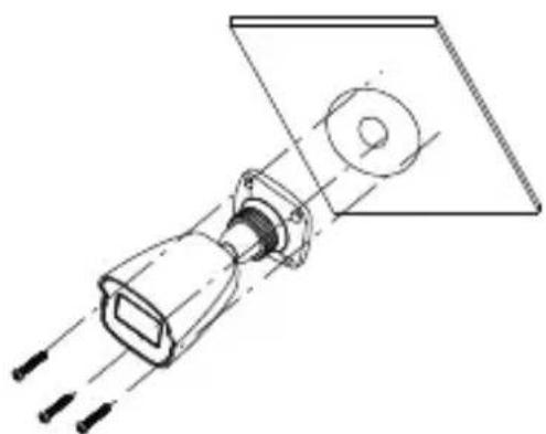
▶Mounting for VLB5/VLB6
- Drill the screw holes and the cable hole on the wall according to the drill template.


- Route and connect the cables.
- Secure the mounting base with camera to the wall with screws as shown below.
natural_image
Technical line drawing of a mechanical assembly with no visible text or symbolsVLB5
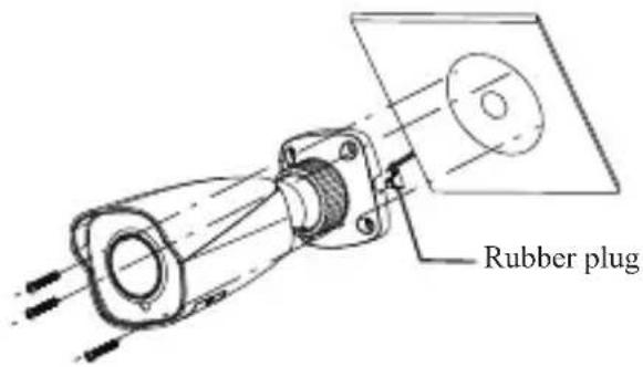
VLB6
- Bracket adjustment. Before adjustment, preview the image of the camera on a monitor and then loosen the fixed ring to adjust the view angle of the camera. Tighten the fixed ring after the adjustment.
- Focus and zoom adjustment (If the camera you get is fixed lens, please skip this step). Open the cover of the camera then adjust the focus and zoom screws to get a clear image. Finally, install the cover back to the camera.
Fixed Ring

VLB5

VLB6
▶Mounting for Dome Camera
● Mounting for VLD5/VLD6M
- Attach the drill template to the place where you want to fix the camera and then drill the screw holes and the cable hole on the wall according to the drill template.

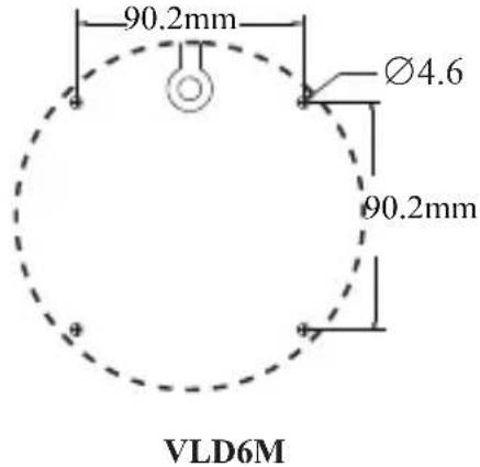
- Rotate the trim ring anticlockwise to remove it from the camera.
- Loosen the screws to open the lower dome. Then route and connect the cables.
- Secure the camera to the wall with screws provided as shown below.


- Three-axis adjustment. Before adjustment, preview the image of the camera on a monitor and then adjust the camera according to the figure below to get an optimum angle.
Pan 0^ 355^

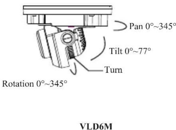
- Install the lower dome back to the camera and fix it with screws. Then put the trim ring onto the lower dome and then rotate it clockwise until it is locked. Finally, remove the protection film softly.

● Mounting for VLT7
- Loosen the set screw to disassemble the camera.

-
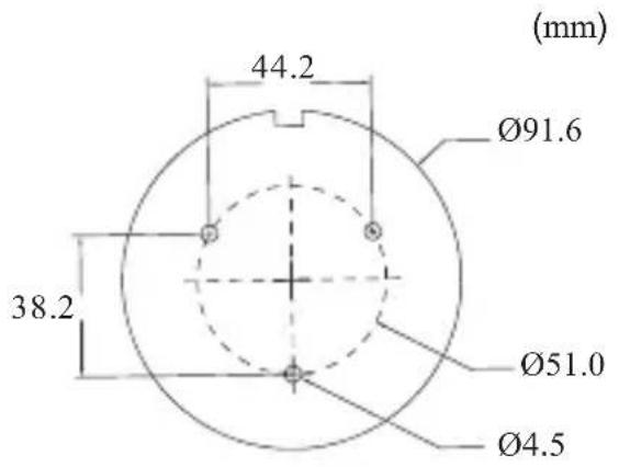
Attach the drill template to the place where you want to fix the camera and then drill the screw holes and the cable hole on the wall according to the drill template.
-
Route and connect the cables. Then secure the mounting base to the ceiling or wall with the screws provided.

natural_image
Pure electrical circuit lines without any symbols- Install the camera unit and enclosure to the mounting base and then adjust the dome to obtain an optimum view angle.

natural_image
Technical line drawing of a camera lens assembly with no text or symbols
- Finally, secure the camera with the set screw.
Specifications
| Specifications\Models | VLB5 VLB6 VLD5 | VLD6M | VLT7 | ||
| Camera | |||||
| Image Sensor | 1/2.9" CM Ω | ||||
| Resolution | 2MP | ||||
| Image size | 1920×1080 | ||||
| Video Output | AHD/TVI/CVI/CVBS (*camera comes defaulted to HD-TVI) | ||||
| Image System | PAL/NTSC | ||||
| Electronic Shutter | Auto; 1/50s~1/100000s(PAL);1/60s~1/100000s (NTSC) | ||||
| IR Distance (feet) | 65.6~98.4 98.4 32.64.65.6 | 65.6~98.4 | 65.6~98.4 | ||
| Frame Rate | 30fps(60Hz),25fps(50Hz) | ||||
| Min. Illumination | Color:0.001lux@F1.2, AGC ON; B/W: 0lux with IR | ||||
| Lens | 2.8mm | 2.8~12mm(varifocal) | 2.8mm | 2.8~12mm(motorized) | 2.8mm |
| Lens Mount | M12 D14 | M12 D14 | M12 | ||
| S/N Ratio | ≥52dB(AGC OFF) | ||||
| Ingress Protection | IP67 IP67 IP67 | 7&IK10 IP67 | &IK10 IP67 | ||
| Functions | |||||
| Function Control | OSD (UTC control) | ||||
| Day &Night | ICR | ||||
| WDR | Yes (digital WDR) | 120dB | |||
| Digital NR | Yes | ||||
| AGC | Yes | ||||
| Auto White Balance | Yes | ||||
| Front Light Compensation | Yes | ||||
| Defog | No | ||||
| HLC | No | No | Yes | Yes | Yes |
| Sharpness | No | ||||
| Mirror | Yes | ||||
| Smart IR | Yes | ||||
| Image Setting | Yes | ||||
| Defect Correction | Auto | ||||
| Others | |||||
| Power Supply | DC12V (±10%) | DC12V (±15%) | |||
| Power Consumption | IR OFF: <1W; IR ON : <3.5W | ||||
| Working Environment | -4°F ~ 122°F, 10% ~ 90%(relative humidity) | ||||
| Dimensions (inch) | 6.6 2.9 2×9 | 8.6 3.2××3.2 | Φ4.7×3.5 | Φ5.6×3.9 | Φ3.7 3.3× |
Federal Communications Commission (FCC) Statements
This device complies with Part 15 of the FCC Rules. Operation is subject to the following two conditions: (1) This device may not cause harmful interference, and (2) This device must accept any interference received, including interference that may cause undesired operation.
FCC Responsible Party:
Speco Technologies
200 New Highway
Amityville, NY 11701
www.specotech.com
- VLB5 /VLB6/VLD5/VLD6M/VLT7
- USER MANUAL
- Warnings
- Introduction
- ● High Resolution
- ● High Transmission Performance
- ● DNR
- ● OSD
- ● White Balance
- - ICR Auto Switch
- ● AGC
- ● Wide Dynamic Range (WDR)
- ● Backlight Compensation (BLC)
- Cables
- Installation
- ▶Mounting for VLB5/VLB6
- ▶Mounting for Dome Camera
- ● Mounting for VLD5/VLD6M
- ● Mounting for VLT7
- Federal Communications Commission (FCC) Statements
- FCC Responsible Party:
Brand : Speco Technologies
Model : VLT7
Category : Video camera