
HYSC100350D - Compressor HYUNDAI - Free user manual and instructions
Find the device manual for free HYSC100350D HYUNDAI in PDF.


| Product Type | Air Compressor |
| Model | HYSC100350D |
| Brand | Hyundai |
| Power Source | Electric |
| Motor Power | 3.5 HP |
| Voltage | 230 V ~ 50 Hz |
| Maximum Pressure | 8 bar (116 PSI) |
| Tank Capacity | 100 liters |
| Displacement | 350 L/min |
| Dimensions (L x W x H) | 85 x 45 x 75 cm |
| Weight | 45 kg |
| Noise Level | 97 dB(A) |
| Lubrication Type | Oil-free |
| Protection Class | IP20 |
| Duty Cycle | S3 50% |
| Safety Valve | Yes, preset |
| Air Filter | Replaceable foam filter |
| Pressure Gauge | Dual analog gauges (tank & regulator) |
| Regulator | Adjustable with locking knob |
| Quick Coupler | 1/4" BSP universal |
| Wheels | 2 wheels + handle for mobility |
| Maintenance | Drain tank daily; check filter monthly |
| Repairability | Spare parts available via authorized service |
Frequently Asked Questions - HYSC100350D HYUNDAI
User questions about HYSC100350D HYUNDAI
0 question about this device. Answer the ones you know or ask your own.
Ask a new question about this device
Download the instructions for your Compressor in PDF format for free! Find your manual HYSC100350D - HYUNDAI and take your electronic device back in hand. On this page are published all the documents necessary for the use of your device. HYSC100350D by HYUNDAI.
USER MANUAL HYSC100350D HYUNDAI
SCREW AIR COMPRESSOR
HYSC75300, HYSC75350D, HYSC100300, HYSC100350D, HYSC150300, HYSC150500D, HYSC200300, HYSC200500D
Combined Manual

natural_image
Line drawings of two Hyundai air purifiers with labeled components, shown from different angles (no text or symbols on the devices themselves)
natural_image
Line drawing of a Hyundai air conditioner unit with no text or symbols on the device itself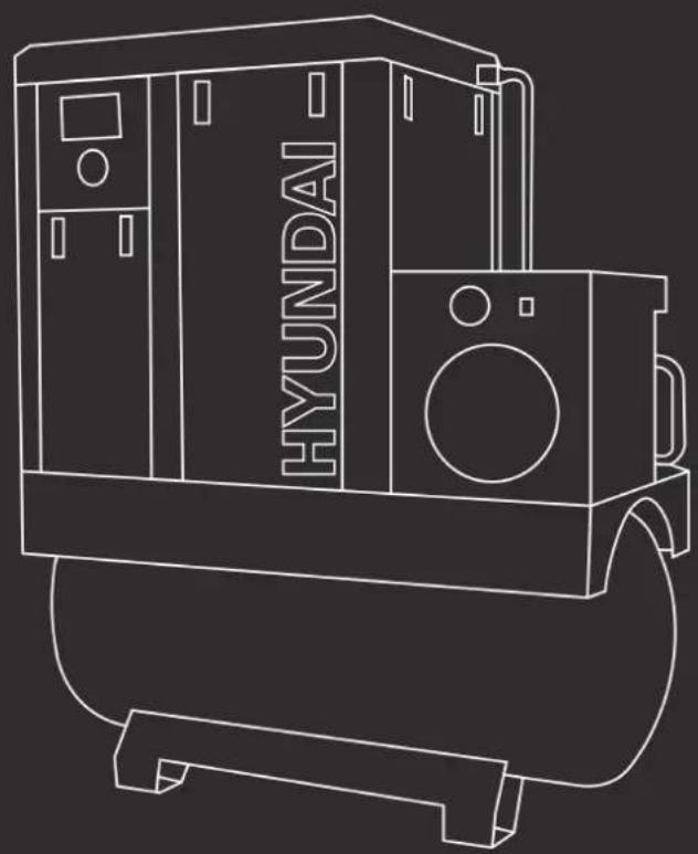
natural_image
Line drawing of a Hyundai air conditioner unit with front-mounted fan (no text or symbols)Before installation and initial operation of the air compressor, please read the manual carefully and clearly learn about relevant information guideline for operation and maintenance about the compressor.
Please hand over the manual and the machine together to the user.
There are important safety information in the technical manual, please save it together with the compressor.
1.1 General Safety Notes.
1.2 The operator of the machine is responsible for, and has a duty of care in making sure that the machine is operated safely and in accordance with the instructions in this user manual. Keep the manual safe and pass it on if the machine is loaned or sold to another user.
1.3 Please note the following safety points.
1.4 The machine should never be left it in a condition which would allow an untrained or unauthorised person/s to operate this machine.
1.5 All due care and diligence should be taken by the operator for the safety of and with regard to those around whilst using the machine.
1.6 Some or all of the following - warning signs, symbols and/or PPE pictograms may appear throughout this manual. You MUST adhere to their warnings. Failure to do so may result in personal injury to yourself or those around you.

DANGER
Indicates a hazard, which, if not avoided, could result in serious injury or death.

WARNING
Indicates a hazard, which, if not avoided, could result in serious injury.

CAUTION
Indicates a hazard which, if not avoided, might result in minor or moderate injury.

NOTE
Indicates a situation that could easily result in equipment damage.
READ and keep the manual safe and pass it on if the machine is loaned or sold to another user.
You MUST fully understand all instructions to ensure you use and operate the machine safely.
Appropriate Personal Protective Equipment (PPE), MUST be worn at all times when operating or repairing the machine.





1.10 Carbon Monoxide (where applicable).

1.11 Carbon monoxide is a colourless and odourless gas. Inhaling this gas can cause death as well as serious long term health problems such as brain damage.
1.12 The symptoms of carbon monoxide poisoning can include but are not limited to the following;
Headaches, dizziness, nausea, breathlessness, collapsing or loss of consciousness.
1.13 Carbon monoxide poisoning symptoms are similar to flue, food poisoning, viral infections and simply tiredness. It is quite common for people to mistake this very dangerous poisoning for something else.
1.14 To avoid carbon monoxide poisoning DO NOT use Petrol/Diesel powered equipment inside any of the following; Home, garage, tent, camper van, mobile home, caravan or boat. This is not exhaustive and if you are in any doubt contact your dealer.
1.15 If you think you have or someone around you has been affected by carbon monoxide poisoning;
1.16 Get them fresh air immediately, by leaving the affected area or by opening doors and windows. If safe and practical to do so make sure that the machine is turned off. DO NOT enter a room you suspect of having carbon monoxide present – instead call the emergency services.
1.17 Contact a Doctor immediately or go to Hospital – let them know that you suspect carbon monoxide poisoning.
1.18 DO NOT use in an enclosed area or moving vehicle.
1.20 General Fuel Safety (where applicable).

CAUTION
ALL FUELS ARE FLAMABLE
1.21 Fire Hazard – keep fuel away from all sources of ignition for example heaters.
Lamps, sparks from grinding or welding.
1.22 DO NOT carry out hot work on tanks that have contained fuel.
1.23 ALWAYS keep the work area tidy.
1.24 ALWAYS clean up spills promptly using absorbent granules and a lidded bin.
1.25 ALWAYS dispose of waste fuels correctly.
1.30 Fueling/De-fueling (where applicable).

CAUTION
ALL FUELS ARE FLAMABLE
1.31 ALWAYS fuel and defuel in a well-ventilated area outside of buildings.
1.32 ALWAYS wear correct, suitable and fit for purpose Personal Protective Equipment (PPE), suggested items are but not limited to safety gloves, overalls.

1.33 When fueling/de-fueling ALWAYS avoid inhaling fumes.
1.34 When de-fueling ALWAYS use a proper fuel retriever.
1.35 ALWAYS carry fuel in the correct and clearly marked container.
1.40 Electrical Safety (where applicable).
1.41 Electricity can kill – NEVER work on LIVE/ENERGISED equipment.
1.42 Prior to carrying out any maintenance work you MUST identify electrical isolation methods and isolate all electrical supplies.
1.43 Prior to use and with all electrical supplies isolated, you MUST check all electrical cables, plugs and connectors for the following;
1.44 Are intact and have no signs of damage, to include but not limited to bare wires, chaffing, cuts and loose wiring.
1.45 If there are any signs of damage, the damaged item MUST be taken out of service until the damage has been repaired by an electrically competent person.
1.46 All trailing cables should be routed so as not to cause any kind of trip hazard.
1.47 NEVER work on or near electricity with wet hands, wet clothing and wet gloves.

risk of electric shock
1.50 Batteries (where present).
1.51 Batteries present a risk if they become damaged by the possible leaking of electrolyte. This electrolyte is an acid and can cause serious burn injuries. Care should be taken when working on or near them. NOTE the electrolyte may be in a liquid or gel form.
1.52 Should you come in to contact with electrolyte you should;
1.53 Remove all clothing contaminated with electrolyte. If you cannot remove then saturate them in water.
1.54 Get medical assistance as soon as possible. You must advise the medical staff of the type of acid.
1.55 Lead/acid battery = dilute sulphuric acid.
1.56 Nickel/cadmium = potassium hydroxide alkali electrolyte.
1.57 Use fresh running water to wash off excess electrolyte, continue this until medical assistance arrives. Make sure that you do not was the electrolyte to another part of your body or face.
1.58 If electrolyte comes in to contact with Eyes the electrolyte needs to be immediately washed away with large amounts of water. Make sure that you do not wash the electrolyte to another part of your face or body.
1.59 Gasses from charging batteries are highly flammable and great care should be taken to charge in well ventilated areas.
1.59.1 There is an explosion risk if the battery terminals are short circuited, when connecting/disconnecting ALWAYS exercise great care so that the terminals or battery leads are NOT allowed to touch and cause a spark. ALWAYS use suitable insulated tools.
1.60 Vibrations (where applicable).
1.61 Prolonged use of hand held (operated) machines will cause the user to feel the effects of/from vibrations. These vibrations can lead to white finger (Raynaud's phenomenon) or carpal tunnel syndrome. This condition reduces the ability of the hand to feel and regulate temperature, causing numbness and heat sensations and may cause never damage and circulatory tissue death.
1.62 Not all factors that lead to white finger disease are known, but cold weather, smoking and other diseases that affect blood vessels and blood circulation as well as large and long-lasting impact of shocks are considered factors in the formation of white finger. Note the following to reduce the risk of white finger and carpal tunnel syndrome;
1.63 Wear gloves and keep your hands warm.
1.64 Take regular breaks.
1.65 All of the above precautions may help reduce the risk of white finger disease but not rule out the carpal tunnel syndrome. Long-term and regular users are therefore
recommended to observe the condition of your hands and fingers. Seek medical attention immediately if any of the above symptoms should occur.
1.70 Noise (where applicable).
1.71 The operating noise of the machine can damage your hearing. Wear hearing protection such as earplugs or ear defenders to protect your hearing. Long-term and regular users are advised to have hearing checked regularly. Be especially vigilant and cautious when hearing ear protection because your ability to hear alarm warnings will be reduced.
1.72 Noise emissions for this equipment is unavoidable. Carry out noisy work at approved times and for certain periods. Limit the working time to a minimum. For your personal protection and protection of people working nearby it is also advisable for them to wear hearing protection.
1.73 See Certificate of Conformity section for Outdoor Noise declaration of conformity.
MACHINE SPECIFIC SAFETY
2.0 DO NOT direct the output jet of air towards people or animals.
2.1 Familiarise yourself with the application and limitations of the air compressor.
2.2 Ensure that the compressor is in good order and condition before use.
If in any doubt, do not use the compressor and contact your service agent.
2.3 Before moving or maintaining the compressor, ensure that the air tank pressure has been vented.
2.4 Only use recommended attachments and parts. Unapproved items may be dangerous and will invalidate the warranty.
2.5 Read the instructions for any accessory used with the compressor. Ensure that the safe working pressure of any air appliance used, exceeds the output pressure of the compressor.
If using a spray gun, check the area selected for spraying is provided with an air change system or adequate ventilation.
2.6 Make sure that the air supply valve is turned off before disconnecting the air supply hose.
2.7 Use the compressor in a well-ventilated area and ensure it is placed on a firm surface.
2.8 Keep tools and other items away from the compressor when it is in use and keep the work area clean.
2.9 Make sure that the air hoses are not tangled, twisted or pinched.
2.10 Keep children and unauthorised persons away from the work area.
2.11 DO NOT disassemble the compressor for any reason if you are not qualified to do so. The unit must be checked by qualified persons only.
2.12 DO NOT operate the compressor within the vicinity of flammable liquids, gases or solids.
2.13 DO NOT touch the compressor cylinder, cylinder head or pipe from the head to the tank as these may be hot and will remain so for some time after shutdown.
2.14 DO NOT operate the compressor without all the safety guards in place.
2.15 DO NOT attempt to move the compressor by pulling the air hose.
2.16 DO NOT use the compressor for a task for which it was not designed.
2.17 DO NOT deface the certification plate attached to the compressor tank.
2.18 DO NOT operate the compressor without an air filter.
2.19 DO NOT allow anyone to operate the compressor unless they have received full instruction.
2.20 DO NOT leave the compressor unattended.
2.21 DO NOT block the ventilation grills.
2.22 DO NOT cover the compressor or restrict airflow around the machine whilst it is operating.
2.23 The air tank is a pressure vessel and the following safety measures apply;
DO NOT tamper with the safety valve DO NOT modify or alter the tank in any way.
DO NOT strap anything to the tank.
DO NOT subject the tank to impact, vibration or heat.
DO NOT allow contact with abrasive or corrosive materials.
YOU MUST drain condensation from the tank daily and inspect side walls for corrosion every 12 months.
2.24 The pressure safety valves on Hyundai compressors have been updated to comply with the latest CE certification standards. The pressure release pull ring has been removed from the valve due to the pull ring being incorrectly used to drain the air from the compressor tank, causing excessive wear to this safety valve. The air and moisture should drained from the tank by releasing the drain valve on the bottom of the tank.
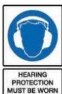
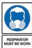
2.25 Correct Personal Protective Equipment (PPE) MUST be worn at all times when operating or repairing this machine. This should include but is not limited to;

HAND
PROTECTION
MUST BE WORN

EYE
PROTECTION
MUST BE WORN

PROTECTIVE CLOTHING MUST BE WORN

HEARING
PROTECTION
MUST BE WORN
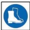
FOOT
PROTECTION
MUST BE WORN

HEAD
PROTECTION
MUST BE WORN

RESPIRATOR
MUST BE WORN
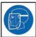
FACE SHIELD
MUST BE WORN
10.0 We do not offer a take back scheme for the recovery of Waste Electrical Electronic Equipment (WEEE) & Batteries.
Instead the responsibility to dispose of WEEE and or Batteries is passed on to you by us.
So when it becomes necessary to dispose of your machine you must take it to your local Civic Amenity Site.
For further information please contact your local Authority for disposal advice.
10.1 You MUST make sure that all unused oil and fuel is disposed of correctly either beforehand or at your local Civic Amenity Site.
Under NO circumstances must any fuel or oil be put down drains.
10.2 Certain products contain WEEE waste which should be disposed of in your domestic waste.
10.3 You MUST recycle WEEE in accordance with your local authority or recycling centre.
10.4 Certain products contain batteries which should not be disposed of in your domestic waste.
10.5 You MUST recycle batteries in accordance with your local authority or recycling centre.
10.6 Unwanted packaging and materials should be stored and taken to a recycling centre so it can be disposed of in a manner which is compatible with the environment.
10.7 The following symbol means that you should 'Reduce – Reuse - Recycle'
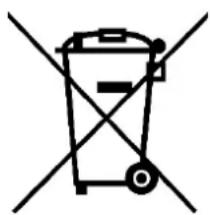
natural_image
Simple line drawing of a trash bin with crossed lines indicating no waste or restriction (no text or symbols)
10.8 We are a member of the VALPAK National Compliance Scheme and our registration number is RM08660.
10.9 For further information about disposal please contact your Local Authority.
10.10 You can also get more advice and guidance about recycling at the following website http://recycle-more.co.uk
10.11 Should you pass this product on to another user either sold or loaned, you MUST pass on this user manual. This will make sure that all other users can use and maintain this machine safely.
1. Introduction
Thank you for purchasing your HYUNDAI product. Please read the user's manual carefully before operating the machine.
The HYUNDAI screw compressor is a two-shaft positive displacement rotating type air compressor; with an alternate name of two-shaft air compressor. The compressor has high and reliable operation characteristics, high gas transmission efficiency characteristics, excellent dynamic balance characteristics, low noise and vibration as well as easy operation and maintenance. It is of long performance life and environment protection. Commonly used in industries of precision machinery and instruments, electronic products and food, Chemical Fiber and Textile, aerospace application and chemistry, decorative coating, medical pharmaceutical, traffic transportation and agriculture etc., Products have a universally acknowledged development prospects.
1.1 Description on the compressor
The screw compressor manufactured by HYUNDAI is an achievement of several years' research and development. The combination of these prerequisite conditions guarantees a long performance life, high reliability and operational efficiency. The products meet all requirements for environment protection.
1.2 Range of application
The machines and units of the series are manufactured according to mature technology and recognized safety rules. The occurrence of the following, however, might cause threat to the user or life and body of the third party, which might cause damage to the machines and other material possessions
- Incorrect range of application
● Operation by unqualified personnel
● Unreasonable modification or transform to the machines
● Nonobservance to safety rules
As a result, all staff that has the right to operate, maintain or repair the machines has to read and obey all safety rules. It can be confirmed by signature if necessary.
The following shall also be obeyed:
● Relevant accident prevention rules
● Acknowledged safety rules
● National laws and regulations.
The machines and units of the series must be operated in perfect technical conditions and must be operated compliance with the range of application and guideline specified in the operation manual. The operators shall have strong safety awareness and fully recognize the risks during the operation of the machines. Any functional breakdowns, especially those that will threaten the safety, must be repaired in time (or ask others to repair it).
The meaning of operating the machines in range of application also includes observing the guideline in the operation manual, check and maintaining as required.
1.3 Maintenance
The machines must be carefully maintained to meet various requirements for screw compressors or compressor units. The machines, therefore, must be carefully maintained during the specified maintenance period, especially in condition of bad working environment.
If there is any breakdown or requirements for spare parts, please contact with compressor manufacturer of my company. If there is any damage to the equipment, the well-trained serviceman of my company will provide excellent after-sales service with the parts manufactured by my company. The authentic parts manufactured by my company are of mature technology and therefore are able to guarantee reliable operation of the machine.
Guarantee
You must understand the machine as well as relevant introductions before operating the machine. If the operation of the machine is inconsistent with the range of application or intended use goes beyond the range mentioned in the manual, the company will not be responsible for safety of the operation.
In following conditions, warranty claim will not be accepted:
- Maloperation
- Improper maintenance
● Misuse of auxiliary materials
● Nonuse of the original parts manufactured by my company - Modifying or repairing the equipment
HYUNDAI refuses to expand the warranty or compensation conditions.
Any arbitrary modifications to the compressor or compressor station or installation of parts which are not authorized by the manufacturer are not accepted by the manufacturer for warranty or compensation conditions.
Safety rules
Safety rules in the operation guideline shall be strictly abided by.
Technical modification
We reserve the right to modify the parts without prior notification during the process of technical research and development.
2. Operating Principle
A complete operating cycle of screw air compressor includes three procedures, inspiration, compression and exhaust. Each pair of gears which are meshing to each other will complete the same operating cycle in succession when the rotor is rotating. To make thing simple and clear, we research the whole operating process of a pair of gears.
a) Procedure of inspiration: As the rotor begins to rotate, one end of the gear gradually demeshes to form a cavity between gears. With expansion of the cavity, there forms some vacuum inside. As the cavity between gears are only connected to air entry, therefore air flows inside under the effect of differential pressure. During the subsequent process of rotor rotation, the male rotor gear ceaselessly demeshes from the gear slot of the female rotor, with on increase in cavity between gears. The cavity breaks from the air entry and the sealed up between the gears. The procedure of inspirations is completed.
b) Procedure of compression: As the rotor is rotating, cavity between gears continuously reduces as rotating gear meshes. Reduction in volume of the air in the sealed cavity between gears causes pressure rise. Thereby the procedure of air compression is carried out.
c) Procedure of exhaust: As the cavity between gears continuously reduces, the air with exhausting pressure is ceaselessly conveyed to exhaust orifice and exhausted out. This process continues till the complete mesh of shaped wires in the end. For the time being, the compressed air in cavity between gears is conveyed to exhaust orifice and completely exhausted out. The volume of sealed cavity between gears becomes zero and the procedure of air compression is carried out.
- Main Technical Data
| Type | HYSC75300 | HYSC100300 | HYSC150300 | HYSC200300 | |
| Motor power | KW | 5.5 | 7.5 | 11 | 15 |
| Air displacement / Exhaust pressure | (m3/min) /Mpa | 0.9/0.7 | 1.2/0.7 | 1.65/0.7 | 2.55/0.7 |
| 0.8/0.8 | 1.1/0.8 | 1.53/0.8 | 2.25/0.8 | ||
| 0.69/1.0 | 0.95/1.0 | 1.32/1.0 | 1.82/1.0 | ||
| 0.6/1.25 | 0.8/1.25 | 1.1/1.25 | 1.55/1.25 | ||
| Cooling mode | Air cooled | Air cooled | Air cooled | Air cooled | |
| Drive mode | Directly connected | Directly connected | Directly connected | Directly connected | |
| Starting mode | Y-△ | Y-△ | Y-△ | Y-△ | |
| Length × Width × Height (mm) | L | 840 | 840 | 910 | 910 |
| W | 600 | 600 | 700 | 700 | |
| H | 880 | 880 | 1000 | 1000 | |
| Net weight | Kg | 185 | 205 | 245 | 255 |
| Noise | dB(A) | 62±2 | 62±2 | 63±2 | 63±2 |
| Diameter of outlet pipe | G3/4" | G3/4" | G3/4" | G3/4" | |
As the products of the company are continuously optimized and upgraded, the information is subject to changes in specifications and relevant data.
| Type | HYSCT5350D | HYSCT100350D | HYSCT150500D | HYSCT200500D | |
| Motor power | KW | 5.5 | 7.5 | 11 | 15 |
| Air displacement /Exhaust pressure | ( m^3/min )/MPa | 0.9/0.7 | 1.2/0.7 | 1.65/0.7 | 2.55/0.7 |
| 0.8/0.8 | 1.1/0.8 | 1.53/0.8 | 2.25/0.8 | ||
| 0.69/1.0 | 0.95/1.0 | 1.32/1.0 | 1.82/1.0 | ||
| 0.6/1.25 | 0.8/1.25 | 1.1/1.25 | 1.55/1.25 | ||
| Cooling mode | Air cooled | Air cooled | Air cooled | Air cooled | |
| Drive mode | Directly connected | Directly connected | Directly connected | Directly connected | |
| Starting mode | Y-Δ | Y-Δ | Y-Δ | Y-Δ | |
| Length x Width x Height (mm) | L | 1800 | 1800 | 1800 | 1800 |
| W | 600 | 600 | 700 | 700 | |
| H | 1560 | 1560 | 1750 | 1750 | |
| Net weight | Kg | 370 | 380 | 505 | 515 |
| Diameter of outlet pipe | 63/4" | 63/4" | 63/4" | 63/4" | |
| Tank volume ( m^3 ) | 0.5 | 0.5 | 0.5 | 0.5 | |
4. Main Structures
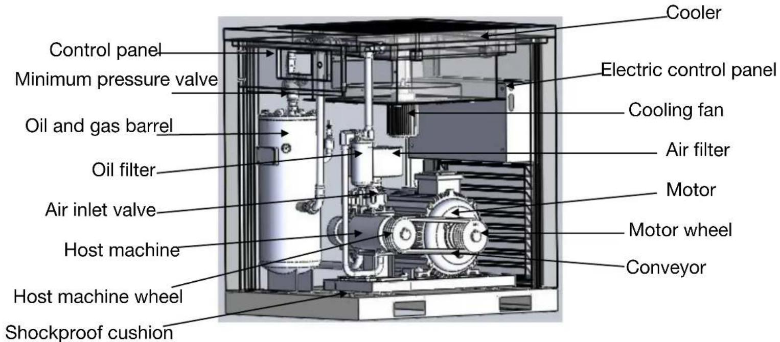
Diagram 1. Conveyor - Type Screw Compressor
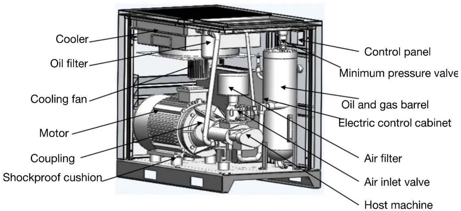
Diagram 2. Directly Connected - Type Screw Compressor

Diagram 3. Directly Connected - Type Screw Compressor

Diagram 4. Directly Connected - Type Screw Compressor
5. Pipeline Flow Diagrams
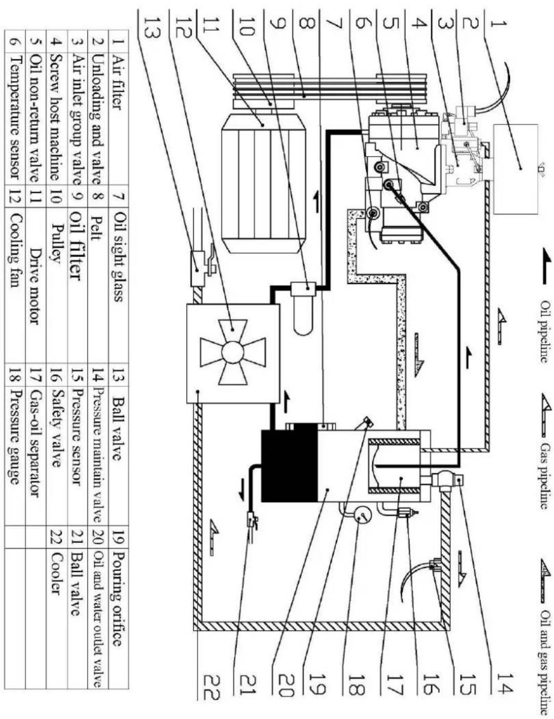
other
| Component | Value | | :--- | :--- | | Air Filter | 7 | | Oil Slight Glass | 13 | | Ball valve | 19 | | Pouring orifice | 19 | | Pressure maintain valve | 20 | | Oil and water outlet valve | 22 | | Safety valve | 22 | | Pulley | 16 | | Drive motor | 17 | | Gas-oil separator | 18 | | Pressure gauge | 18 | | Temperature sensor | 12 | | 5 Oil non-return valve | 11 | | Screw host machine | 10 | | Air inlet group valve | 9 | | Unloading and valve | 8 | The diagram shows a schematic of the system with numbered components and flow paths. The bottom section includes a schematic diagram of the system with labeled parts (e.g., 'Oil and gas pipeline', 'Gas pipeline', 'Oil pipeline', etc.).Diagram 5. Conveyor - Type Screw Compressor Flow Diagram
| 1 | Air filter | 7 | One-way valve | 13 | Safety valve | 19 | Oil and water outlet valve |
| 2 | Air inlet group valve | 8 | Temperature sensor | 14 | Gas-oil separator | 20 | Cooler |
| 3 | Unloading and valve | 9 | Oil filter | 15 | Pouring orifice | 21 | Cooling fan |
| 4 | Screw host machine | 10 | Bail valve | 16 | Pressure gauge | ||
| 5 | Drive motor | 11 | Pressure maintain valve | 17 | Oil sight glass | ||
| 6 | Centric coupling holder | 12 | Pressure sensor | 18 | Oil and gas barrel |

Diagram 6. Directly Connected Screw Compressor Flow Diagram
- Electric Principle Diagram

Diagram 7. Electric Principle Diagram For Split Type Main Controller

7. Warnings and Announcements
7.1 Power distribution for the machine
a) According to the power, voltage frequency and other characteristics of the air compressor, select and use matched power supply and suitable power line (If conditions permit, excellent power line with properties of anti-high temperature and anti-aging shall be equipped to avoid breakdown in the air compressor caused by power line or power).
b) Cross area of the power line shall be no less than the data in Table 2.
Table 2. Minimum cross area of the power line (Copper wire mm ^4 )
| Code of the product | Motor power ( KW ) | Cross area ( mm2 ) |
| HYSC75300 5.5 | 50 | |
| HYSC100300 7.5 | 6 | |
| HYSC150300 11 | 10 | |
| HYSC200300 15 | 16 |
c) Proper air switch shall be selected and equipped by professional electrician according to the power and voltage of the air compressor to protect the power electrical system for safety guarantee, which is shown in Picture 9

natural_image
Close-up of a blue circuit breaker with three leads and three terminal blocks, no visible text or symbols on the main body.Picture 9. Air Switch
d) The air compressor must be reliably grounded to avoid the dangers caused by electricity leakage and static electricity.
e) Air compressor with large displacement shall use a separate set of power supply unit to avoid impact on the normal operation of other equipments, or it goes against the normal operation of the air compressor( It causes to the operation of screw protective devices)
7.2 Announcements
a) In order to avoid the damage caused by jolt during the process of storage and transportation has been screwed when it leaves the factory. The user has to lock in the transportation fastening screw and loosen the fasteners before using the equipments, which is shown in Picture 10
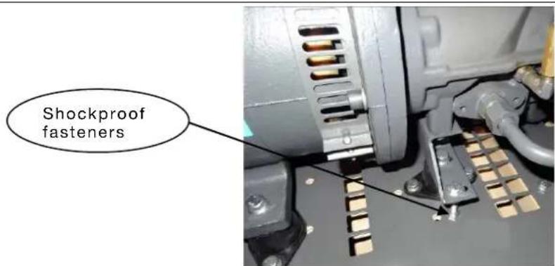
Picture 10.
b) Debugging of the new machine must be operated by appointed or authorized person by the company.
c) Operators must read, comprehend and follow the relevant operating procedures, announcements and maintenance specifications in the manual.
d) The air compressor without air storage tin can only be used after being equipped with air storage tin.
e) The air compressor shall not be arbitrarily altered or set the rated operating voltage to avoid overload damage to the motor.
f) Air compressor shall be operated indoor, with good ventilation and a temperature that is less than 45^ C.
g) The end of the inlet wire of power supply shall be equipped with a terminal to guarantee that the bolt in the terminal is fixed and won't become flexible. The wire must be installed by professional electricians( As shown in Picture 11).
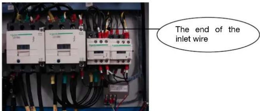
Picture 11.
h) It is strictly prohibited that the compressor operates under a pressure less than 0.4Mpa in long-term basis.
i) Keep the lubricating oil between the range of upper and lower limits of the oil indicator. Mixture of different brands of lubricating oils is strictly prohibited to avoid serious accident caused by coke accumulation in pipeline system.
j) It is strictly prohibited to examine and repair the electrical equipment and circuit under the condition that the power supply is not off.
k) It is strictly prohibited to examine and repair the pressure volume and pressure pipeline.
I) Timely get rid of the moisture in gas and oil barrel.
m) The exhaust temperature shall be between 70 and 105°C.
n) Cleansers which are inflammable, explosive and volatile cleaners cannot be used to maintain and
clean the parts. Safe dissolvent free from corrosion shall be used instead.
o) If there is breakdown alarm in the compressor, please don't start up the machine forcefully. Please timely find out the cause and deal with it accordingly.
7.3 Warning symbols
Table 3
| S.N. | Name | Symbol | Description |
| 1 | Safety in electricity utilization |  | Make sure the working supply voltage is off during operation |
| 2 | Danger! Electricity! |  | Watch out charged body, leakage body and other electrical parts |
| 3 Danger warning |  | Pay attention to and be careful about relevant warning information | |
| 4 | Reading the instruction |  | Read the instruction before operation |
| 5 Ignition hazard |  | Inflammable and explosive materials shall be away form the machine | |
| 6 | Exploration hazard |  | Please don't weld or repair the air storage tank |
| 7 | Electric shock hazard |  | Please don't place the equipment in wet places or outdoors to avoid electricity leakage due to reduction in electrical insulation resistance |
| 8 No air | leakage No air leaka |  | |
| 9 | Caution, hand injury |  | Don't touch transmission part |
| 10 | Rotational direction of the motor | 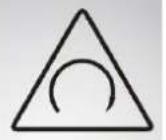 | Check rotational direction of the motor during the process of first starting up or changing wire to avoid serious breakdown to the machine |
| 11 | Danger, hot! |  | Hot surface, avoid burns |
8. Equipment Installations
Installation site choosing and heat elimination and ventilation system
An installation site plan must be made to correctly use the air compressor to create good environment for its operation and maintenance. A reasonable site must meet the following requirements.
a) Air compressor must be installed indoor, which is clean, dry, ventilated, dust free and harmful gases free.
b) Operating environment temperature shall not exceed 45^ C. And the relative humidity of the surrounding atmosphere shall be less than 80%.
c) The floor for installation shall be solid, smooth and horizontal.
d) If the planning site is an air compressor station, proper compressed air processing devices, valves, pipelines and pressure containers shall be equipped according to relevant provisions. In order to assure good heat dissipation and maintenance space, the distance between the air compressor and the wall shall be no less than one meter and space of more than 1.5 meters shall be reserved on the top to avoid wind bridge which is formed by the outlet hot wind and inlet cold wind. Exhaust devices shall be equipped in the machine room which is badly ventilated.
9. Equipment Operation
9.1 Transportation shockproof fixation bolt shall be loosened before the
operation (Please refer to what is stated in item 7.2 in announcements)
9.2 Air compressor can only be come into service when it is equipped with air storage tank(as what is shown in Table 1-Main Technical Data).
9.3 Test run of the new machine
a) Testing voltage on page 12, item 7.1-a, shall meet the requirements in relevant provisions. According to the requirement of item 7.1-d on page 12, it shall be grounded. According to the items 7.1-b and c on page 12, it shall be connected to the power line. The cross area and length of the power line shall meet the provisions in Table 2 on page 12.
b) Check the oil level in gas and oil barrel to see if it is between the upper and lower limits.
c) To guarantee safety of starting up, it shall be firstly confirmed that there are no personnel, tools and inflammable and explosive materials in the unit.
d) Pour approximate 0.2 liters lubricating oil which is specially used for air compressor to the air inlet valve and turn the hand piece if the machine for several turns to avoid damage in dynamic and static tray in air compressor due to oil shortage.(A funnel with net is used for filtrating to prevent foreign matters from entering the hand piece.)
e) Charge electricity to the control panel in air compressor
f) Trial operation test: Trail operation shall be done for two or three times before the formal operation. The purpose of Trial operation, starting up the machine and shut it down immediately, is to check if the rotating direction of the air compressor is correct or not and if there is abnormal noise and vibration.
g) Normal operation: Press the start button again to start the operation of the air compressor.
h) After the starting up of the machine, motors with power more than 11kw shall be set as Y- starting up, the initial operation is slowly speeded up in way of Y shape and automatically changed to quick speeding up in way of shape.
i) Stop: When the stop button is pressed, the air compressor stops to run. The compressed air in pressure pipeline will be discharged by load relief valve when the machine is stopped, getting ready for the next no load starting up of the equipment. It is a normal phenomenon if some weak sound of air discharging can be heard.
9.4 Safety protection
a) Motor protection Table 4
| S.N. | Breakdown description | Breakdown display | Causes |
| 1 | Phase shortage | Shutdown | Breakdown in power supply, contactor and motor circuit |
| 2 | Overload | Shutdown | Increase in load capacity or mechanical breakdown |
| 3 | Locked-rotor | Shutdown | Increase in load capacity or mechanical breakdown |
| 4 | Imbalance | Shutdown | Three- phase voltage of the power supply is not stable or circuit breakdown in motor |
| 5 | Short circuit | Shutdown | Serious electricity leakage, short circuit between circles of the motor or error in current setting |
b) Air (Oil) exhaust standard exceeding protection
When temperatures of air (oil) exhausting reach the set warning temperature, there will be alerting information on the controller and give an alarm. When the temperature reaches set breakdown temperature, the controller execute the order and shutdown
When the phase sequence of the three-phase power supply is different from that set in the controller, the controller is unable to output the starting up signal and the motor cannot start operation. For the time being, you have to exchange any two power lines and see the rotating direction of the motor.
c) Exhaust pressure overpressure protection
When the exhaust pressure is high than the upper limit value, the controller execute the order and shutdown
d) Sensor failure protection
When pressure sensor and temperature sensor are in breakdown of disconnection, the controller execute the order and shutdown.
10 Operations and Maintenance
10.1 Routine operation and maintenance (According to provisions in Table 5)
10.1.1. Examining and maintaining before operation
a) Check to see if the equipment is clean and complete.
b) Check and maintain the intact of the electrical elements and firmness of the grounding.
c) Check and maintain the reliability of the fasteners.
d) Check and adjust the tension of the belt and change it if necessary.
e) Check, adjust and change the coupling or bumper block if necessary.
f) Check, add and change the lubricating oil if necessary.
➢ Oil level shall be between the upper and lower red line of the oil indicator, as what is shown in Picture 12.
[NO TEXT]

Special lubricants for screw machine as shown in Picture 1 should be used.

Picture 13.
Refueled oil should be filtered through Cleaned funnel(Filtering precision is 14um)
The used oil should be discharged before the change of lubricant as shown in Picture 14.

Picture 14.
g) Check to see if it is necessary to discharge the condensate water in the gas and oil barrel.(Slightly open the liquid discharge valve on the bottom of gas and oil barrel and discharge the condensate water till the lubricating oil flows out.)
h) Check, clean and replace the filter element of the air filter if necessary as shown in Picture 15.

Picture 15.
i) Check, clean and replace the oil-gas separator if necessary as shown in Picture 16.

Picture 16.
j) Check, clean and replace the oil filter if necessary as shown in Picture 17.
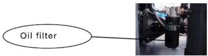
Picture 17.
m) Check and clean the cooler if necessary as shown in Picture 18.
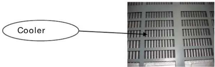
Picture 18.
10.1.2 Starting up Checking
a) Check the operating button to see if it is in normal condition.
b) Check whether there are phenomena of abnormal noise vibration and oil leakage.
c) Check the instruments of pressure gauge, oil thermometer, ammeter and indicator light etc. to see if they are in normal condition.
d) Check the oil return pipe to see if it is in normal condition.
e) Check the pressure of the automatic stop and that starting up to see if it is in normal condition.
f) Check the unloading valve to see if it is deflating or not when the machine stopped.
Check the exhaust temperature to see if it is in normal condition.
q)Check to see if the temperature is in normal condition
h ) Check the voltage and electric current to see if they are in normal condition.
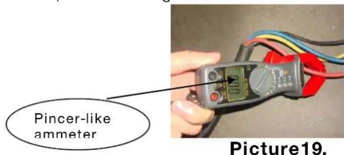
i) Check, clean and replace the safety valve if necessary.
Check the motor insulation resistance.
k) Record the voltage, current, air pressure, exhaust temperature and oil level every day and take notes of the working time, maintenance status and abnormalities per shift.
Maintenance plans
Table 5
| S.N. | Checking Items | Working content | Maintenance cycle Remarks | ||||||
| Day | Week | Month | Half year | A year | Two years | ||||
| 1 Fastener | Check the bolts and transmission components | ☆ | The bolts and transmission components can't fall off or loosen. | ||||||
| 2 Coupling Check the coupling | ☆ | Concentricity is normal with no damage. | |||||||
| 3 | Strainer of oil return pipe | Check the strainer | ★ | No sundries | |||||
| 4 | Condition of oil return in transparent return pipe | Make sure the oil return is normal | ☆ | Oil return is fluent | |||||
| 5 Unloading valve | Make sure the machine is stopped and | ☆ | Normal stop, unloading and deflating | ||||||
| 6 | Lubricating oil | Check the level and quality of oil | ☆ | The oil level should be within the alerting line, without oxidation discoloration | |||||
| 7 | Air (oil) exhausting temperature | Make sure the venting temperature | ☆ | The normal temperature is between 70°C and 105°C | |||||
| 8 | Voltage and current | Check the voltage and current. | ☆ | Within 1.2 times of that of the rated current | |||||
| 9 Air filter Cleaning | ☆ | Replace the filter element only | |||||||
| 10 | Drainage in Gas and oil barrel | Water drainage | ☆ | Discharge from the oil discharge valve | |||||
| 11 | dustproof gauze | Cleaning and maintenance | ☆ | Take out and clean | |||||
| 12 | Pipeline system | Check the situation of oil leakage and air leakage. | ☆ | No phenomenon of oil leakage | |||||
| 13 | Circuit system | Line terminal or displaying information | ☆ | No phenomena of information alarming or wire decrustation | |||||
| 14 Oil strainer | Checking and cleaning | ☆ | Replace the filter element only | ||||||
| 15 | Filter element of oil-gas separator | Cleaning and replacement | ★ | Replace the filter element only | |||||
| 16 | Mechanical seal for the host machine | Checking the leakage | ☆ | The quantity of oil leakage is less than 1.5g/h | |||||
| 17 | Motor insulation | Checking the insulation resistance | ★ | More than 2MΩ when the voltage is 500V | |||||
| 18 | Relief valve | Checking the sensitivity of the action | ☆ | In condition of rated pressure, it can discharge when the discharging ring of the relief valve is pulled with a force less than 1 kg and the sundries are cleared off. | |||||
| 19 | Pressures of automatic stop and automatic start up | Checking the sensitivity of the action | ☆ | Stop pressure and start-up pressure are in normal condition. | |||||
| 20 | Cooler | Maintenance and cleaning | ☆ | Clean the surface dirt in the way of blowing | |||||
| 21 | Indicator of the oil level indicator | Checking the clarity | ☆ | Replace it when the oil level is fuzzy. | |||||
| 22 | Belt and pulley | Checking the firmness or replacement. | ☆ | Extrude the center of the belt with the thumb to make sure it is 10 to 15 mm and with no damage. | |||||
Notes: “☆”refers to parts that are maintained by users, “★”refers to parts that are entrusted to service center. “○”refers to parts that must be replaced after the new machine running continuously for 500 hours, then replace them after 3000 hours’ work. The maintenance parts are those whose working time are less than 6000 hours.
10.1.3 Processing method of long-term shutdown
10.1.3.1 Equipment should be sealed if it is shutdown for a long period of time.
a) Clean the equipment and spread some antirust oil on the parts which are easy to be rusted.
b) Electric equipment such as motor control panel etc., all Valves, tables, indicators shall be wrapped up with plastic paper or oil paper.
c) The water in the oil cooler (gas and oil barrel), gas cooler and air storage tank shall be all discharged..
d) Covering all the equipment with plastic paper or some other similar materials.
e) Transportation fixed screw should be locked if the transfer storage space is changed.
10.1.3.2 To restart the sealed air compressor, the Motor insulation resistance should be measured first (No less than 1 MΩ). then do as the operating instructions on page 16 item 9.3. The air compressor sealed more than one year should replace the lubricant.
- Breakdown and Elimination Table 6
| S.N. | Breakdown phenomena | Causes Breakdown elimination | |
| 1 | Motor starting up failure | No input voltage or the voltage is in abnormal condition. | Check the power supply circuit |
| Phase failure (The motor gives out "buzz-buzz" sound) | Check the power line terminal, electric controller and on-line terminals | ||
| Connection error in power phase position | Adjust the phase-sequence and repair or replace the main controller | ||
| Blown fuse | Check and make sure there is no error in circuit and replace the fuse | ||
| Burning of AC contactor or failure | Repair or replace | ||
| Failure of pressure switch (Pressure sensor) Repair or replace | |||
| Motor burning out and bearing failure | Repair or replace | ||
| Clamping stagnation in dynamic tray in hand piece or block up caused by bearing failure | Repair or replace | ||
| Temperature sensor operation protection | Find out the causes and eliminate the breakdown | ||
| Current protector operation protection | Find out the causes and eliminate the breakdown | ||
| 2 | Story frequent starting up | Failure in starting up the time delay unit | Check and reset the time delay unit and main controller or replace it |
| Serious leakage in pipeline Check the leaking parts and eliminate the breakdown | |||
| Volume of air storage tank is not large enough | Add air storage tanks or replace larger air storage tanks | ||
| 3 | Exhaust (oil) temperature is too high | Environmental temperature is too high | Increase the air volume in the unit room |
| The cooler is dirty and with bad heat dissipation | Clean the cooler | ||
| Blocking in oil pipeline Check and get the pipe through | |||
| Failure of temperature sensor Repair and replace | |||
| The lubricating oil is not enough Add lubricating oil | |||
| Failure in cooling fan Repair or replace | |||
| 4 | Too low exhaust pressure | Failure in pressure switch, force sensor and main controller | Repair adjust and replace |
| Too much air consumption | Repair the pipeline, buy more air compressors and control the air volume | ||
| Serious leakage in pipeline | Repair and replace if necessary | ||
| 5 | Great consumption of lubricating oil | No use of special lubricating oil | Exchange the special lubricating oil |
| Fasterers become flexible. Host bearing wear or damage in motor | Repair or replace | ||
| 6 | Abnormal noise and vibration | Conveyor wear Replace the belt | Wear or looseness in the coupling Check, fasten or replace |
| Too high exhausting temperature | Increase air volume and decrease the environmental temperature or repair the temperature control valve and cooling system | ||
| 7 | Early deterioration in lubricating oil | No use of special lubricating oil | Exchange special lubricating oil |
| Failure in empty the used lubricating oil | Empty the used oil and add new special lubricating oil | ||
| 8 | Oil leakage in air filter when air filter when it is shutdown | Breakdown in air inlet valve | Repair or replace |
| Gas return in minimum pressure valve Repair or replace | Unloading solenoid valve fails to deflate | ||
| V shape rotation belt is too tight | Repair and adjust the hand piece | ||
| Low input voltage( The wire is too long and the diameter is too small) | Adjust the wire | ||
| Too great differential pressure in pipeline (Blicking in filter element) | Repair or replace | ||
| Too small) | too small) | ||
| 9 | Great current or trip caused by slow rotation of the motor | Serous imbalance in three-phase voltage Check and eliminate the breakdown | Poor contact or current capacity of the breaker is not large enough |
| Poor contact or current capacity of the breaker is not large enough | |||
| Blocking in air filter | Clean and replace the filter element | |
| Breakdown in air inlet valve Repair or replace | ||
| Blocking in oil-gas separator | Repair or replace | |
| Leakage in unloading solenoid valve | Repair or replace | |
| Slipping in V shape rotational belt | Repair, adjust and replace |
| 10 | Failure of rotating in cooling tan | No use of special lubricating oil Exchange for special lubricating oil | ||
| Too high temperature, great current and operation of overload protector | Repair or replace | Check the circuit and AC contractor | ||
| Phase failure | Repair or replace | Check the circuit and AC contractor | ||
| Breakdown in temperature controller and main controller | Repair or replace | Repair or replace | ||
| Inconformity in three-phase resistance value (Motor burnt out) | Repair or replace | Repair or replace | ||
| Breakdown in tan bearing | Repair or replace | Repair or replace | ||
- Directly-Connected Type Screw Machine
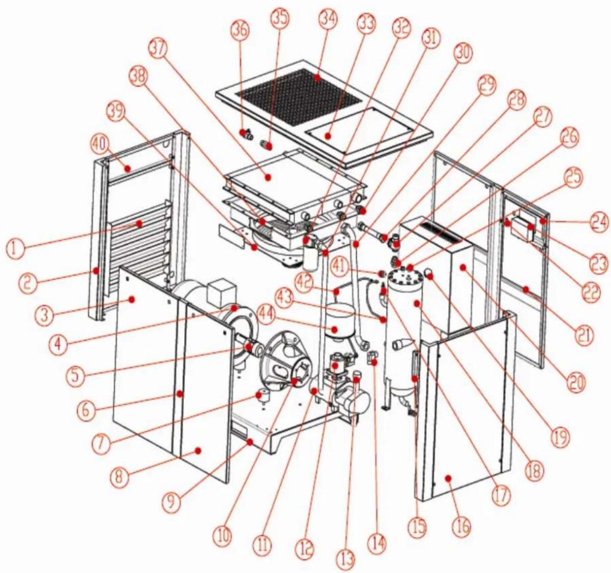
List of the parts of directly-connected type screw machine
| S.N. | Name | Quantity | S.N. | Name | Quantity |
| 1 | Right shutter | 1 | 24 | Control shutter | 1 |
| 2 | Right front side vertical shaft | 1 25 Bend | 1 | ||
| 3 | Front and back right shutters | 1 26 Adjustable pipe joint | 1 | ||
| 4 | Motor | 1 | 27 | Minimum pressure valve | 1 |
| 5 | Coupling | 1 | 28 | Air outlet pipe | 1 |
| 6 | Back-central gatepost | 1 | 29 | Head oil inlet | 1 |
| 7 | Anti-vibration pad | 1 | 30 | Oil inlet joint of the cooler | 1 |
| 8 | Back-left gatepost | 1 31 Oil filter assembly | 1 | ||
| 9 | The main baseplate | 1 | 32 | Oil filter joint | 1 |
| 10 | Center bracket | 1 | 33 | Camp of the head cover | 1 |
| 11 | Screw hand piece | 1 | 34 | Head cover | 1 |
| 12 | Air inlet valve | 1 | 35 | Gas supply pipe | 1 |
| 13 | Exhausting pipe of hand piece | 1 | 36 | Ball valve | 1 |
| 14 | Bend | 1 | 37 | Fin type heat exchanger | 1 |
| 15 | Oil mirror | 1 | 38 | Wind cover assembly | 1 |
| 16 | Left shutter | 1 | 39 | Fan | 1 |
| 17 | Relief valve | 1 | 40 | Deflation opening board | 1 |
| 18 | Oil-gas barrel | 1 | 41 | Pressure gauge of the oil-gas barrel | 1 |
| 19 | Refueling cover of the oil-gas barrel | 1 42 | Fine oil differentiating return pipe | 1 | |
| 20 | Electric control cabinet | 1 43 U | nloading pipe 1 | ||
| 21 | Front-left shutter | 1 | 44 | Air filter assembly | 1 |
| 22 | Emergency "stop" button | 1 | |||
| 23 | Controller | 1 |
13. Conveyor- type screw machine

List of Parts of All Cover Conveyor Type Screw Conveyor
| S.N. | Name | Quantity | S.N. | Name | Quantity |
| 1 Left shutter 1 27 | Oil return pipe of oil and gas barrel | 1 | |||
| 2 Digital display panel 1 28 | Main return pipe of he head | 1 | |||
| 3 | Emergency "stop" button | 1 | 29 | The air filter assembly | 1 |
| 4 | Motor pulley | 1 | 30 | Oil filter | 1 |
| 5 | Motor | 1 | 31 | Oil filter joint | 1 |
| 6 | Electric control cabinet | 1 | 32 | Oil filter fixed board | 1 |
| 7 | Vertical shaft on left side of the front shutter | 1 33 | Oil filter exhausting tubing | 1 | |
| 8 | Automatic tension spring of the conveyor | 1 34 Oil inlet bend | 1 | ||
| 9 | Front shutter | 1 | 35 | Oil return bend | 1 |
| 10 | Anti-vibration platform | 1 36 Exhaust shutters | 1 | ||
| 11 | The main base-plate | 1 | 37 | Head cover | 1 |
| 12 | Anti-vibration pad | 4 | 38 | Oil-gas cooler | 1 |
| 13 | Vertical shaft on right side of the front shutter | 1 39 Exhaust bend | 1 | ||
| 14 | Shutter on the right side | 1 | 40 | The protective cover of the cooler-fan | 1 |
| 15 | Transportation fixed board | 1 | 41 | Cooling fan | 1 |
| 16 | Host frame | 1 | 42 | Control panel | 1 |
| 17 | Head exhaust pipe of hand piece | 1 43 Belt | 3 | ||
| 18 | Oil-gas barrel | 1 | 44 | Hand piece of screw | 1 |
| 19 | Bend | 1 | 45 | Headpiece pulley | 1 |
| 20 | Vertical shaft on right side of the back shutter | 1 46 | A fine differentiating oil return pipe | 1 | |
| 21 | Built-in oil-gas fine differentiator | 1 47 Unloading pipe | 1 | ||
| 22 | Back shutter | 1 | 48 | Air intake valve | 1 |
| 23 | Deflation opening board | 1 | 49 | Oil-gas barrel pressure gauge | 1 |
| 24 | Exhausting pipe of oil and gas barrel | 1 50 | Refueling plug of Oil-gas barrel | 1 | |
| 25 | Vertical shaft on left side of the shutter | 1 51 Air intake pipe joints | 1 | ||
| 26 | Minimum pressure valve | 1 | |||
14. Directly-Connected Type Screw Machine

List of the parts of directly-connected type screw machine
| S.N. | Name | Quantity | S.N. | Name | Quantity |
| 1 | front shutter | 1 | 25 | Oil mirror | 1 |
| 2 | Vertical shaft on left side of the front shutter | 1 26 | Oil inlet plug of Oil-gas barrel | 1 | |
| 3 | Left shutter | 1 | 27 | Ball valve | 1 |
| 4 | Electric control cabinet | 1 | 28 | Air filter element | 1 |
| 5 | Motor barrel | 1 | 29 | Air filter cover | 1 |
| 6 | Gridding plate | 1 | 30 | Back shutter | 1 |
| 7 | Motor barrel back cover | 1 31 | Vertical shaft on right side of the back shutter | 1 | |
| 8 | Oil filter | 1 | 32 | Right shutter | 1 |
| 9 | Oil filter base | 1 33 | Vertical shaft on right side of the front shutter | 1 | |
| 10 | adjustable straight connector | 1 | 34 | Plastic panel | 1 |
| 11 | Cooling fan | 1 | 35 | Display control panel | 1 |
| 12 | The protective cover of the cooler & fan | 1 | 36 | Emergency stop switch | 1 |
| 13 | cooler | 1 | 37 | 90°adjustable connector | 1 |
| 14 | Head cover plate | 1 | 38 | Main return pipe of air end | 1 |
| 15 | Fan cover plate | 1 | 39 | Air inlet valve | 1 |
| 16 | Discharge pipe straight connector | 1 40 Host machine | 1 | ||
| 17 | Discharge pipe of oil-gas barrel | 1 41 | Oil inlet straight connector | 1 | |
| 18 | Minimum pressure valve | 1 | 42 | Air end support | 1 |
| 19 | Flange cover of oil-gas barrel | 1 43 | Rubber Anti-vibration foot | 1 | |
| 20 | Built-in oil-gas fine differentiator | 1 44 oil return valve | 1 | ||
| 21 | Oil return pipe straight connector | 1 | 45 | Temperature sensor | 1 |
| 22 | Pressure gauge | 1 | 46 | Discharge pipe of air end | 1 |
| 23 | Oil return pipe of oil and gas barrel | 1 | 47 | Main base plate | 1 |
| 24 | Safety valve | 1 | |||
SCREW AIR COMPRESSOR CONTROL USER
OPERATING MANUAL

NOTICE

Please read instruction manual before usage

Installation of MAM-8** can be performed only by professional technicians

Assembling position shall be considered carefully during mechanical installation in order to ensure good heat dissipation and reduce electromagnetism interferences

Wiring shall be performed respectively according to regulations for heavy and weak current to reduce electromagnetism interferences

Surge absorber must be communicated with inductive load such as AC contactor of output control of relay

Output wiring shall be inspected carefully before switch up

Earthing terminal of this body part shall be earthed correctly (the third type of earthing) to increase product's capacity of resisting signal noise.

Motor's rated current (current for stopping instrument automatically) shall be set according to rated current indicated on motor's name plate × overload current multiplication factor of motor/ 1.2
Features:
● LCD Chinese / English display
● With control functions of starting, stopping and operation for motor.
● With protection functions of preventing reverse rotation of air compressor.
● Temperature measurement and control
● Automatic adjusting of rate of load and controlling of pressure balance
- Selections of remote and local control
- Selections of interlocking and independent
● Function of RS485 communication
2、Common Failures and Causes....19
9、Electrical diagram....21
Basic Operation
1. Button Explanation

Figure 1.1.1
I — Start Button: Press this button to start the compressor.
- -Stop button: Press this button to stop the compressor.
S ——Set Button/ Loading / unloading Button: After modification, press this to confirm and save modified data; When the compressor is running ,press this button to load or unload under a certain pressure.
—Move up button/increase button: Data at current position is increased by pressing this button when data are modified; Menu is moved upwards when menu is selected.
—Move down button / Descending button: Data at current position is descended by pressing this button when data are modified; menu is moved downwards when menu is selected.
— —Shift button /Enter button: This button services as shift button when data are modified and services as enter button when menu is selected.
C ——Back button / Reset button: This button services as back button when operate menu to come back
Parent menu; resetting is carried out by pressing this button for a little long time when failure shutdowns
2. Indicator instructions
Power: After controller power on, power LED light
Run: Compressor operation, run LED light.
Alarm: Early warning, the fault light flashes; fault shutdown, fault lights lit, clear fault, reset off.
3. Display of status and operations
The display screen will be as follow when the units are powered on:
SCREW COMPRESSOR
After power on, screen show this page
After 5 seconds, the main page will show up as:
PRES: 0.60MPa
SYS STOP C01

Main page
Press shift button, the main page will show up as:
TEMP: 80°C
SYS STOP C01
Main page
Press "Move down button" to enter into Menu Selection Interface:
RUN PARA.
USER PARA.
Level 1 menu screen
FACTORY PARA.
MOD PARAMETER
Level 1 menu screen
4. Operating parameters
Press "Move down button" or "Move up button" to move the black cursor to "RUN PARA.", press enter button to pop up submenu:
MOTOR(A) A-0100
B-0100 C-0100
Continuously press "Move down button" you can see run parameters and run state parameters as follows:
Fan current, Total run time, Total load time, This run time, This load time,
Oil filter time, O-a filter time, Air filter time, Lube time, Grease time, Belt time...etc.
5. User Parameter (Customer Parameter):
In primary menu, press the move button to move the black slider to the "USER PARA." menu, press the shift button to switch to the following menu:
LOAD PRES:
00.65MPa
on , Switch to the following interface requirements to enter
a user password
PASSWORD:0***
After showing this interface, The first bit data or password started flashing, press "increase button" or "descending button" to modify the flashing data equal to the first bit of password. Press the shift button, move the cursor to the next data bit, modify the current data is equal to the second password data, Accordance with the above, modify the third and fourth Finally, press the "Set button" to confirm the input, the system verify the password is correct, switch to the following interface:
LOAD PRES:
00.65MPa
The upper right corner with "* "prompt said
the system has passed the password authentication
In as shown above interface, press "enter button", then the data of loading pressure start to flash, users can press "increase button" or "Descending button" to modify the present data. When finished, press "Set Button" to confirm and save. the controller prompt sends out the short voice to tip.
6. Customer Parameter and Functions
| Parameters | Preset Value | Functions |
| LOAD PRES. | *.*MPa | LOADING PRESSURE VALUE |
| UNLOAD PRES. | *.*Mpa | UNLOADING PRESSURE VALUE |
| FAN START TEMP | ***°C | Control the fan starting. This value will be set as “120°C” if there is no fan present or the fan is not required to be protected.” |
| FAN STOP TEMP | ***°C | Control the stopping of the fan |
| MOTOR DELAY T 0008S | When using the controller to protect the motor, it is required that the time set here will not meet the impulse starting current of the motor, the value here must be longer than the STAR DELAY TIME plus LOAD DELAY TIME | |
| FAN DELAY T 0006S | When using the controller to protect the motor, it is required that the time set here will not meet the impulse starting current of the motor. | |
| STAR DELAY TIME | 0006S | Star pressure descending start delay time. |
| LOAD DELAY TIME | 0002S | The loading delay time after star pressure descending. |
| EMPTY DELAY T | 0020M | Load free continuous running time, the machine will automatically stop after this time |
| STOP DELAY TIME | 0010S | The machine will not stop until the load free running status lasting till this time |
| START DELAY T 0100S | Machine can not be restarted before this set time after stopped or over time operation at load free state | |
| START MODE LOCAL/FAR | When the remote mode is set, both the button on the controller and the remote control button can turn on and off the machines; When the near mode is set, only the button on the controller can turn on and off the machines. | |
| LOAD MODE | AUTO/MAN U | When the manual mode is set, the Load/Unload function can only be executed by pressing “load/unload ‘button |
| COM MODE | BAN/COMP./BLOCK | When this is set as “BAN” the communication function is not availableWhen this is set as “COMP.”the Controller as a slave, in accordance with MODBUS protocol communications with external devicesWhen this is set block, block control active |
| COM ADDRESS | 0255 | Communication address |
| SEQ STATE SLAVE | Service as main or assistant air compressor during interlocking operation. The MAIN controls the SLAVE | |
| TOGGLES TIME 9999 Hours | During interlocking operation, if one air compressor continuously operates for time period more than time set here and rest time of one air compressor in interlocking network has reached the time set here, alternative rest is achieved by starting the resting air compressor and stopping the operating air compressor | |
| SEQ NUMER 0016 | Number of air compressors in interlocking network during interlocking operation | |
| SEQ LOAD PRES. *.*MPa | The main air compressor searches for one device in the interlocking network for loading or starting when main air compressor’s gas supply pressure is less than the value set here during interlocking operation | |
| SEQ U.L. PRES. *.*MPa | The main air compressor searches for one device in the interlocking network for unloading or stopping when main air compressor’s gas supply pressure is more than the value set here during interlocking operation | |
| SEQ DELAY | 0030S | The least waiting time that the main air compressor needs to continuously sends control commands two time |
| OIL FILTER | 0000H | Reset time for the duration of oil filter changing |
| O/A FILTER | 0000H | Reset time for O/G Separator changing |
| AIR FILTER | 0000H | Reset time for gas filter changing |
| LUBE | 0000H | Reset time for Lubricate Oil Changing |
| GREASE | 0000H | Reset time for Lubricate Grease Changing |
| BELT | 0000H | Reset time for Belt Grease Changing |
| OIL FILTER | 9999H | Set this value to “0” will make the oil filter alarm not available |
| O/A SEPARATOR | 9999H | Set this value to “0” to disable the O/G separator alarm function |
| AIR FILTER | 9999H | Set this value to “0” to disable the alarm function of gas filter |
| LUB | 9999H | Set this value to “0” to disable the time alarm of lub. oil |
| GREASE | 9999H | Set this value to “0” to disable the time alarm of Lub. Grease |
| BELT | 9999H | Set this value to “0” to disable the time alarm of belt. |
| LANGUAGE SEL | ENGLISH/C HINESE | Set this value to “EN”, Display text in EnglishSet this value to “CH”, Display text in Chinese |
| USER PASSWORD | **** | Customer could modify the user password |
7. Factory Parameters
The factory parameters can be looked over and modified with manufacturer password, but its operation method is the same as that of user parameters. Please refer to following table for main functions and purposes.

Manufacturers enter the correct password press set button, switch to the factory parameters of the interface as follows
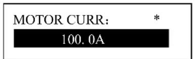
Continuously press “Move down button” you can see factory parameters as follows: FAN CURR, PRE-ALARM TEM, STOP TEMP, STOP PRESS, MAX U.L. PRESS, TOTAL RUN TIME, TOTAL LOAD TIME, RESET FAULT.....ect.
Factory parameters "run time", "phase sequence protection," "Frequency Selection" and the time need check super password to changes.
8. Manufacturers and function
| PARAMETER | Initial Value | Functions |
| MOTOR CURR | MAXIMUM OVERLOAD VAULE OF THE MOTOR /1.2 | After the starting delay time, when the motor current is greater than 1.2 times of the set value and less than 4 times of the set value, the unit will jump as per overload feature. |
| FAN CURR | Maximum allowable fan motor overload value/1.2 | Same as above |
| ALARM T. | 105°C | Pre-alarm when the temperature reaches this set value |
| STOP T. | 110°C | Alarm when the air exhausting temperature reaches this set value. |
| STOP P. | 1.00MPa | Alarm and stop the machine when the air supply temperature reaches this set value |
| MAX U.L. 0.80MPa | The Unload Limit Pressure in the CustomerParameter must be set lower than this value. | |
| RUN TIME ****Hours | The manufacturer can modify the total running time | |
| LOAD TIME ****Hours | The manufacturer can modify the load running time | |
| CLR FAULT **** | Input the history failure password to clear all the history failures. | |
| CUR UN.BAL. 0006 | When (the max. phase current / min. phase current) is not greater than (1+set value), the unbalance protection will stop the machine. If the set value is greater than 15, the unbalance protection will be unavailable. | |
| LACK PAHSE 005.0 | If set time of phase failure ≥20 seconds, phase failure doesn't function; If unbalance protection is activated, it will stop operation. | |
| DATA ****-**-** | The manufacturer input the product date of the unit. | |
| SERIAL ***** | The manufacturer input the product No. of the unit | |
| PHASE PRO. ON/OFF | ON: Select sequence protectionOFF: Not select sequence protection | |
| POWER FREQ | 50H | Set the power frequency |
| HIGH VOL. ****V | Controller detects the voltage higher than the set value, the shutdown protection, reported voltage is too high. Set this value to 0000, the high voltage function is no function | |
| LOW VOL. | ****V | Controller detects the voltage lower than the set value, the shutdown protection, reported voltage is too low. Set this value to 0000, the low voltage function is no function |
| LOW T PRO- | -48°C | Controller detects the temperature is lower than this value, display temperature is too low, not allowed to start the air compressor |
| TIME LIM | 0000H | When the compressor run time is greater than TIME LIM set, the controller will stop the compressor and alarm;If the value set as '0000' the function is disable. |
| ALM STOP | 0010H | Warning time over here to set, compressor report "warning too long" and stop |
| COM SET PARA | ON/ | |
| PARA1 | **** |
9. Calibration parameters
Calibration parameter used to set the controller data, Does not allow unauthorized users to view and modify
FACTORY PARA.
MOD PARAMETE
View calibration parameters as follows, Press the "Move down button", Move the cursor to
the "MOD PARAMETE" menu, then press "Enter button", Verify the password, you can view the calibration parameters. The calibration parameter and functions as list
| PARAMETER | Initial Value | Functions | |
| MOTORA | TARGET CUR 0000 | Enter the current value, the controller will detect user input value divided by the current to the current value, calculate the current coefficient | |
| COEF 1.000 | Calibration current, the input coefficients. Controller displays the current value = sample value × COEF | ||
| CUR ***.*A | Displays the current controller sampling current values. This value is the real value can not be set. | ||
| MOTORB | TARGET CUR 0000 | Enter the current value, the controller will detect user input value divided by the current to the current value, calculate the current coefficient | |
| COEF 1.000 | Calibration current, the input coefficients. Controller displays the current value = sample value × COEF | ||
| CUR ***.*A | Displays the current controller sampling current values. This value is the real value can not be set. | ||
| TARGET CUR 0000 | Enter the current value, the controller will detect user input value divided by the current to the current value, calculate the current coefficient | ||
| COEF 1.000 | Calibration current, the input coefficients. Controller displays the current value = sample value × COEF | ||
| CUR ***.*A | Displays the current controller sampling current values. This value is the real value can not be set. | ||
| TARGET CUR 0000 | Enter the current value, the controller will detect user input value divided by the current to the current value, calculate the current coefficient | ||
| COEF 1.000 | Calibration current, the input coefficients. Controller displays the current value = sample value × COEF | ||
| CUR ***.*A | Displays the current controller sampling current values. This value is the real value can not be set. | ||
| CUR ***.*A | Displays the current controller sampling current values. This value is the real value can not be set. | ||
| FANB | TARGET CUR 0000 | Enter the current value, the controller will detect user input value divided by the current to the current value, calculate the current coefficient | |
| COEF 1.000 | Calibration current, the input coefficients. Controller displays the current value = sample value × COEF | ||
| CUR ***.*A | Displays the current controller sampling current values. This value is the real value can not be set. | ||
| FANC | TARGET CUR 0000 | Enter the current value, the controller will detect user input value divided by the current to the current value, calculate the current coefficient | |
| COEF 1.000 | Calibration current, the input coefficients. Controller displays the current value = sample value × COEF | ||
| CUR ***.*A | Displays the current controller sampling current values. This value is the real value can not be set. | ||
10. The operating authority and password
Controller provides multiple passwords and access management, according to different levels of passwords, providing different levels of operating authority, different levels of passwords and permissions as follows:
- user's password: fixed as : ____
Permissions: allows to modify the load pressure unload pressure, fan start temperature, fan stop temperature, start and stop mode, loading method, communication mode, communication address and linkage parameters.
-
User Password: set as:
-
Permissions: Allows to modify all user parameters.
-
man ufacturers sales password: this password can be modify, set to : ____
Permissions: Allows users to modify all the parameters, the user password, and the parameters of some manufacturers, manufacturers selling password.
- man ufacturers Password: factory fixed: ____
Permissions: Allows users to modify all the parameters, the user password, and the parameters of some manufacturers, manufacturers selling password.
- Calibration Password: set as:
Permissions: allows you to modify the current parameters of the calibration parameters
- Super Password: set as:
Permissions: Allows users to modify "run time" "phase sequence protection" "power frequency" "max run time"
2. Technical parameters and functions
1、Digital input: Digital input of 3# circuit; digital output of relay of 5# circuit;
2、Simulation quantity: Pt100 temperature input of 1# circuit; 4\~20mA input of transducer of 1# circuit; two groups of three phase current input(CT provided);
3、Input voltage of phase sequence: three phase 380V/220V;
4、Controller's power supply: AC20V、50Hz、10VA;
5、Measurement range displayed:
①、Oil temperature:-50\~150°C; precision: ±1°C.
②、Air temperature:-50\~150°C; precision:±1°C.
③、Operation time: 0\~999999 hours.
④、Measurement range displayed for current:0\~999.9A.
⑤、Pressure: 0\~1.60MPa. Precision: 0.01Mpa.
6、Phase-sequence protection: When protector inspects wrong phase, response time≤2s (optional);
7、Protection of motor: this controller has five basic protection functions for main motor and fan's motor
①、block protection: When working current reaches to from 4 times to 8 times of set current after finish starting, response time ≤0.2s;
②、Short circuit protection: when testing current reaches above 8 times of set current, response time≤0.2s;
③、Protection of phase failure: in case of phase failure of any one phase, operation time equals setup time;
④、Unbalance protection: when currents of any two phase differ 60\~75%, operation time equals set time;
⑤、Protection characteristics of reverse time limit of overload (time unit: second), please see following table (table 2.1.1), multiple=lactual / lset
motor operates with delay time according to overload factors and operation time shown in following table (table 2.1.1) when motor's working current is larger or equal to from 1.2 times and 3.0 times of set current.
| Time parameters\lactual/lset | ≥1.2 | ≥1.3 | ≥1.5 | ≥1.6 | ≥2.0 | ≥3.0 |
| Operation time (S) | 60 | 48 | 24 | 8 | 5 | 1 |
Table 2.1.1 curve table of reverse time limit for protection of motor
8、Temperature protection: when actual temperature measured is larger than temperature set; response time≤2s;
9、Contact capacity of output relay: 250V,5A; Contact endurance 500000 times
10、Error of displayed current is less than 1.0%.;
11、RS485 communication
3. Type and specification
1. Instruction of type

flowchart
graph TD
    A["MAM 870 (B) (T) (V) (40)"] --> B["Serial"]
    A --> C["B: pressure sensor; K: Pressure switch"]
    A --> D["With voltage detection"]
    A --> E["Maximum working current matching"]
2. Specification table for power of suited motor
| Specification\Parameter | Current range (A) | Suited main motor power (KW) | Remark Description |
| MAM870 (20) | 8~20 | 4~10 | |
| MAM870 (40) | 16~40 | 8~20 | |
| MAM870 (100) | 30~100 | 15~50 | |
| MAM870 (200) | 80~200 | 40~100 | |
| MAM870 (400) | 160~400 | 80~200 | |
| MAM870 (600/5) | 100~600 | 50~300 |
4. Installation
1. Installation of transducer
The transducer shall be installed at place where motor's line current (rated current) can be measured, thus controller can be set according to instructions on motor's name plate, the detailed dimensions as followed:
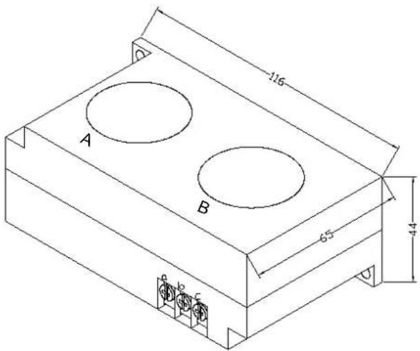
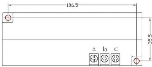
Figure 4.1.2. Install dimensions of
Figure 4.1.1. Structural dimensions of CT1 ( 36 through hole)
CT1


Figure 4.1.3. Structural dimensions of CT2 ( 10 through hole) CT2
Figure 4.1.4. Install dimensions of
2. Controller Installation
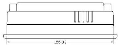
The controller is installed as plate. Room should be left around controller for wiring. The specific dimensions are as follows:
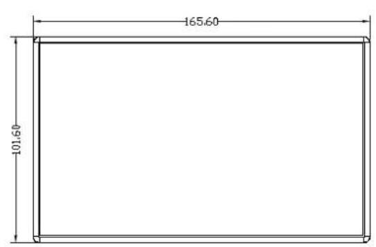

natural_image
Technical line drawing of a rectangular electronic component with internal pins and a dimension label (no text or symbols beyond the measurement)
natural_image
Technical line drawing of an electronic device housing with mounting holes and internal components (no text or symbols)Figure 4.1.5 Controller structure dimensions

other
| Dimension | Value | | --------- | ----- | | Total Length | 156.8 | | Total Height | 93 | The chart displays a rectangular area with two vertical lines, one labeled '93' and the other '156.8'.Figure 4.1.6 Hole size
3. Terminal arrangement diagram

Figure 4.2.1 Terminal arrangement diagram
Terminal blocks of controller:
1 is common terminal COM1; 2 is input terminal for emergent stop signal; 3 is remotely controlled on/off signal input terminal; 4 terminal is used to detect oil filter blocked; 6 is RS485 A; 7 is RS485 B; 8 is the simulated ground (Earth); 17 and 18 are the AC20V power source; 22、23 terminals are Pressure Sensor signal input; 24、25、26 terminals are motor mutual inductor CT1 input; 27、28、2 terminals are Fan mutual inductor CT2 input; 30、31 terminals are Temperature Sensor signal input; 19、20、21 terminals Used to detect the phase sequence and voltage; 13 terminals is common terminal of output relay; 14 terminals controls fan; 15 terminals controls load valve; 16 terminals controls angle-shaped contactor; 17 terminals controls star-shaped contactor; 18 terminals controls main contactor.
NOTE: Eelectromagnetism coil shall be connected with surge absorber during wiring, and dotted lines are extendable functions.
5. Control principles
1. Local Automatic control
①. Press down start button for starting: (Y-△start)
There is fives of self-test after controller is energized and it can not be started by pressing start
button .The air compressor starts by pressing start button after self-test finished. The course of compressor's start as followed: KM3 and KM2 are energized → Y-type status of start → delay time is reached (Y-△change-over time); KM3 is de-energized (KM1 and KM3 are interlocked) and KM1 is energized → motor operates with △ type to finish start. During the course of starting, all electromagnetism valves are de-energized to achieve no load start.
②. Automatic operation control:
When the motor is started to running in status and load the magnetic valve with power applied after a certain period of delay. Air compressor is loaded and pressure inside gas tank begins to increase. When increased air pressure is more than higher pressures limit (value of unload pressure), electromagnetism valve for loading is de-energized and electromagnetism valve for discharging is energized, meanwhile, the air compressor operates without load. If air pressure decreases to set lower pressure limits (value of load pressure), the electromagnetism valve for loading is energized again and electromagnetism valve for discharging is de-energized. Air compressor operates normally to increase pressure in air tank. If the unload run time exceeds the set delay time of non-load, the compressor will automatically stop motor's operation to achieve automatic shutdown after works without load for long time. Only when pressure decreases to lower pressure limits, the motor start operation according to course of starting, then circularly repeat this step.
③. Manual loading/unloading under automatic status
When compressor in automatically runs state and runs at unload operation, press down load or unloading button, the electromagnetism valve for loading joggles a little and comes back to unloading status; if the pressure is less than relief pressure, the electromagnetism valve for loading is energized and it returns to unloading status until gas supply pressure becomes larger than relief pressure and device is at loading status. Unloading is performed when press down unloading button "S". If the pressure is higher than loading pressure, the electromagnetism valve for loading is de-energized and turns to status of loading until gas supply pressure is less than loading pressure. If pressure is less than loading pressure, the unloading button do not function.
④. Normal shutdown:
Press the button, the load magnetic valve will loss power and the unload magnetic will be applied with power, after a while of delay (stop delay), the motor contactor will loss power, the host and fan will stop running, after the restarting delay completed, the unload magnetic will loss power. Only pressing the button could restart the motor.
⑤. Control of preventing frequent starting
Press stop button to stop operation; Air compressor can not be started up immediately after shutdown due to operation without load for long time or failure shutdowns, and it can be started up again when remaining delay time is zero which the time display window of the controller in a variety of shutdown state shows.
2. Remote automatic control
Remote automatic control and local automatic control are basically same, but the difference is that starting up or stopping of devices can be achieved by means of control of remote switch.
3. Local manual control
Control of starting and stopping are same as automatic control, but device is in status of
unloading operation after finish starting up and loading is carried out by pressing down loading and unloading button to load. When gas supply pressure is more than relief pressure, the device unloads automatically. If doesn't press loading, unloading button, the device will operate with unloading until stops without load. During unloading, press loading and unloading button to load. During loading, press loading and unloading button to unload.
4. Remote Manual Control
The remote automatic control is almost the same as the local manual control, the only difference is that the start and stop of the unit is controlled by remote control.
5. Network control
①: When communication method is set “computer”, network control between computer and controllers can be achieved
②: When communication method is set "interlocking", network control between controllers can be achieved, but the main air compressor only can service as 1# compressor.
6. Temperature control of fan
When exhausting temperature is higher than fan's starting temperature, fan operates; when exhausting temperature is lower than fan's stopping temperature, fan stops operation.
7. Failure shutdown and emergency shutdown
When electrical failure or high exhausting temperature appears during process of operation, the controller stops motor's operation immediately. Air compressor only can be started up after failure is eliminated. In case of emergency, press down emergency stop button to cut off power of controller and contactors
6. Early-warning and prompts
1. Indication of early warning of oil filter
①. Early warning for blockage of oil filter
The controller can display the message on the text display to remind the operator that “the air filter is blocked” by checking the pressure difference switch operating state.
②. Set the running time alarm of the air filter
The Text displays “OIL FILTER LIFE END” when the using time of the oil filter terminates.
2. Indication of early warning for air filter
The Text displays "AIR FILTER LIFE END" when the using time of the oil filter terminates.
3. Indication of early warning for oil separator
The Text displays "O/A LIFE END" when the using time of the oil separator terminates.
4. Indication of early warning for lubricating oil
The Text displays "LUBE LIFE END" when the using time of the lube terminates.
5. Indication of early warning for grease
The Text displays "GREASE LIFE END" when the using time of the grease terminates.
6. Indication of early warning for belt
The Text displays “BELT LIFE END” when the using time of the belt terminates.
7. High air temperature warning
Controller detects the air temperature high, the text display "HIGH TEMPERATURE"
7. Controller protection
1. Motor protection
MAM-870 air compressor controller provides all-round protection functions of short-circuit, locking, phase failure, overload, imbalance for motor.
| Electronic failure | Failure Display Reason | |
| Short circuit | Display failure “HOST/FAN SHORT” | Short circuit or rated current is set by mistake |
| Blocked | Display failure “HOST/FAN BLOCK” | Too large load, bearing wear and other mechanical failure |
| Overload | Display failure “HOST/FAN OVER CARRY” | Too large load, bearing wear and other mechanical failure |
| Phase failure | Display failure “HOST/FAN LACK PHASE” | Power supply, contactor and phase failure of motor |
| Unbalance | Display failure “HOST/FAN UNBLANCE” | Poor contact of contactor, inside open-loop of motor |
2. Gas Exhaust Over-temperature Protection
When the Air exhaust temperature is higher than the upper limit of set temperature, the controller would be stopped, the display will show "HIGHT T".
3. Non-reversing Protection of Air Compressor
When three-phase supply phase sequence connected to the air compressor is not the same with that set for the controller, the on-site failure is displayed as “PHASE REVERSAL”, as a result, the controller cannot start up the motor. Then just change any arbitrary two-phase power lines leading to check the rotation of motor.
4. Overpressure Protection of Pressure Supply
When the gas exhaust pressure is higher than the upper limit of set pressure, the controller would be stopped for warning, the on-site failure is displayed as "HIGH P".
5. Malfunction Protection of Sensor
When pressure sensor or temperature sensor is disconnected, the controller would be stopped for warning. The on-site failure is displayed as “**SENSOR FAULT”.
8. Removal of Common Failures
1. Failures Review
When a fault occurs, the controller in the main interface displays the current fault content. For example, when the pressure sensor failure, it displays the following interface:
STOP:
P SENSOR FAULT
- Common Failures and Causes
| Failure | Reason | Disposal method |
| Air Exhaust Temperature too high | Bad vent condition, Oil lacking etc. | Check the vent condition and lubricant amount etc. |
| Temperature Sensor Failure | Cable off or PT100 damaged | Checking the wiring and PT100 |
| Over Pressure | The pressure too high or the pressure sensor failure | Check the pressure and the pressure sensor |
| Pressure Sensor Failure | Cable off, Sensor damaged or the cable connected reversed | Check the wiring and sensor transformer |
| Lack Phase | Power phase lacking or the Contactor terminal damaged | Check the power and contactors |
| Overloaded | Voltage too low, tubes blocked, Bearing Wear off or other mechanical failure or wrong set data etc. | Check the set data, Voltage, bearings, tubes and other mechanical system. |
| Unbalance | Power unbalance, Contactor damaged or the internal open of the motor | Check the power, contactors and the motor |
| Rotor Lock | Voltage too low, tubes blocked, Bearing Wear off or other mechanical failure or wrong set data etc. | Check the set data, Voltage, bearings, tubes and other mechanical system. |
| Short Circuit | Wrong Wiring, Incorrect Data setting etc. | Checking the wiring and set the data correctly |
| Wrong Phase Sequence | Reversed Phase sequence or phase off | Check the wiring |
| Overload or Rotor locking during starting process | Host start time set to a valueless than the star angel time delay | Reset the host starting time to be longer than star angel delay + Load delay time |
| Main Contactor activate time to time | The emergency button loose Check the wiring | |
| Air Exhaust Temperature too high | Bad vent condition, Oil lacking etc. | Check the vent condition and lubricant amount etc. |
| Temperature Sensor Failure | Cable off or PT100 damaged | Checking the wiring and PT100 |
| Over Pressure | The pressure too high or the pressure sensor failure | Check the pressure and the pressure sensor |
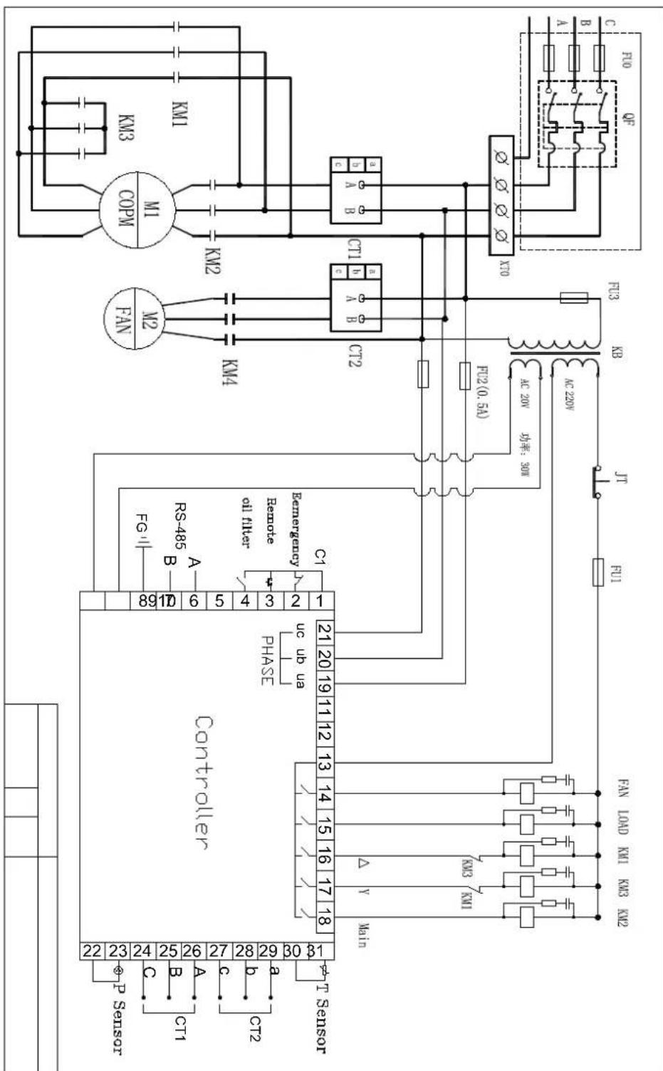
- Electrical diagram
Air Dryer
Notice item
A place shall not to be installed.
A place where the storm directly hit and moisture
A place where dusty and corrosive gas
A place a poorly ventilated or confined space
A place where with shake and leaning
A place where there is heat near the input wind
A place where narrow and no maintenance and operations
The temperature should be below 38°C
(B) Installation
A horizontal position does not special installation of foundation
The power distribution should be according to the power、voltage、frequency on the nameplate
Install a separate power control switch
When two machines put together, it should be keep their distance, it must be to
avoid the hot exhaust of a machine is another inhalation
(C) Stop and run
Stop running the machine, and then start running at least 3-5 minutes later. Low load or low temperature, the machine will stop and run interval. It is normal
Air-cooled (MID -TEMP) air dryer flow diagram
Exit and entrance
Refrigerant pressure meter
Evaporator
Water separator
Expansion valve
Refrigerant filter
Bypass valve
Pressure controller
Drainage
Refrigerant compressor
Condenser fan
Condenser
Air-cooled (MID -TEMP) air dryer type and technical date
Type, Air volume, Use condition
Entrance temp. ≤45°C
B condition temp.38°C
Work pressure 0.3-1.0MPa (over pressure, accept custom)
Refrigerant
Other, accept custom
Motor power
Power source
Input/output dia
Measurement
Weight
The fault and exclude way of the dryer
Cannot start
Check the power supply voltage is normal or not; refrigerant pressure is normal or not (normal is stop state 5-12kg); 220V/12V transformer, 12V is normal or not; the start and stop button on the panel is normal or not, AC contactor coil of contact point is normal or not; the pressure switch, thermal relay is reset or not, the above fault is AC contactor can not pull
The AC contactor can pull but can not start and run
Check the compressor connection line, the contact of wiring plug is normal or not, capacitor is damaged or decreased capacity, the overload protector is damaged or not; compressor coil is open or short circuit Above shall confirm the damaged parts and replace with the new parts
Can start but stop a little late
Low pressure fault: not enough refrigerant, check the leak point, after confirm the leak point and repair it and then reevacuated and filling the refrigerant
High pressure fault, too dust on the condenser, or the condition temperature is too high, it should wash the condenser and improve the ventilation condition
The gas is reduced or not by the compressed air
Ice block or too much dust, the reason of ice block: the load is reduced, the pressure controller to be failure. Remedy is to readjust the temperature controller or pressure switch., the method is: start, watching the pressure meter gauge, when reach 4 kg, the machine should be stopped, watch several times. If can not be adjusted. It should be replaced the dust should be cleaned.
Not cooling (the drainage has a long time without water discharge) but can hear the compressor running sound. Owing to the damage to the compressor valve plate, it should replace the compressor, it is not compress the refrigerant (the refrigerant pressure gauge pointer does not move)
The head frost
Remedy should accord to the article 3 ice block fault (adjust the fan control switch)
Fault exclude
The fault of air dryer and external factors, the way of fault exclude is as following. The air pressure to be reduced too much
| Feature | Reason | Fault Exclude |
| The pressure is too large between the operate condition and the press | The pipe valve is closed | Open the valve |
| The small of pipe dia. | Enlarge the pipe dia. | |
| The pipe is too long, elbow, connector are too much | Redesign the pipe system | |
| The leaking in connector | Check and repair | |
| The filter is blocked | Replace the filter | |
| Not enough air capacity | The using capacity is over the rate of air compressor | Replace the bigger rate air compressor |
| Evaporator iced | Pressure switch fault | Adjust the pressure or replace the switch |
| The expansion valve blocked | Replace the expansion valve |
Poor water removal
| feature | reason | fault exclude |
| Site water | The bypass valve not closed tightly | Closed the bypass valve tightly |
| The air is not through the air dryer | Open the dryer exit and entrance valve | |
| Air flowing and pressure too much | Replace the mach air dryer | |
| Drainage poor | Clean or replace | |
| The drain pipe is higher the auto-drainage | Redesign the pipe | |
| The air compressor is not mach the air dryer | Redesign the cleaning system | |
| The evaporated high temperature indicate abnormal | The evaporated temperature too high | Check the air compressor air load |
| The pollution air or poor ventilation | Select the position or improve the ventilation | |
| The expansion valve blocked | Replace the valve | |
| The refrigerant leaking C | heck the leaking point and filling the refrigerant | |
| The meter damaged | Replace the meter | |
| Feature | Reason | Fault Exclude |
| No power source Fuse | broke n or fuse switch tripped | Confirm the power source leak of phase ,short circuit or not |
| Check the fuse or closed the fuse switch | ||
| Wire broken | Check the wire , repair | |
| Power source normal but can not start | Power source abnormal or the dia. of wire too small | Select according to the rate voltage on the nameplate |
| Switch poor | Replace the switch | |
| Connector poor | Replace connector | |
| Overload relay poor | Replace overload relay | |
| Capacitor poor | Replace capacitor | |
| Start relay poor | Replace start relay | |
| High-low pressure switch poor | Replace high-low pressure switch | |
| Temperature switch poor | Replace temperature switch | |
| Compressor poor | Replace compressor | |
| Switch normal but cannot start | High-low voltage switch tip no reversion | Check and reset |
| Electromagnetic no reversion | Check and reset | |
| High temperature no reversion | Check and reset | |
| Temperature setting poor errors | Reset or replace the switch | |
| Compressor poor | Replace compressor |
| Feature | Reason | Fault Exclude |
| Evaporated temperature indicate too low | Evaporate temperature meter poor | Replace the evaporator temperature meter |
| Expansion valve blocked | Replace expansion valve | |
| Temp. switch or pressure switch setting too low | Adjust and reset | |
| Refrigerant leaking Check the leaking point and filling the refrigerant | ||
| Evaporated temperature indicate too high | Condition temp. too high Select the position and improve the ventilation | |
| Hot air bypass valve fault | Adjust or replace the bypass valve | |
| Condenser blocked Clean | ||
| Too air capacity | Redesign | |
| The compressor valve plate poor | Replace the compressor | |
Poor after start
| Feature | Reason | Fault Exclude |
| High voltage tripped ,reversion but can not start | Shortly after start, wire short circuit ,charred taste | Chain control wire and switch reconfiguration |
| Pressure switch poor | Replace pressure switch | |
| Fan poor | Replace fan | |
| Overload tripped | Find reason and check relay | |
| Condenser dusted | Clean | |
| Too much refrigerant | Reduction in refrigerant | |
| Too high position temp Select the position and improve the ventilation | ||
| Expansion valve blocked | Replace expansion valve | |
| Dry filter blocked | Replace dry filter | |
| Overload relay tripped | Start relay poor | Replace start relay |
| Capacitor poor | Replace capacitor | |
| Pressure switch poor | Replace pressure switch | |
| Compressor overload Reduce the air capacity or replace the right dryer | ||
| Too high temperature of position | Select the position and improve the ventilation | |
| Too low of relay current | adjust | |
| Relay connect poor | Adjust or replace | |
| Phase lack | Check the reason | |
| Connector poor or connect point poor | Clean or replace connector | |
Auto drain system poor
| Feature | Reason | Fault Exclude |
| Drain poor The drainage | pressurelow1.5kg/cm2 | Use the pressure 2-10 kg/cm2 drainage |
| Drain valve damaged | Replace drain valve | |
| Drainage lean or damaged | Adjust or replace drain valve | |
| Drainage filter blocked | Clean or replace drainage filter | |
| Too high using pressure | Use rate pressure | |
| Outfall blocked | Clean |
Dryer Controller User Guide
Technique Index
- Te mperature display range: -20\~100°C (The resolution is 0.1°C)
• Power supply: 220V±10%
● Temperature sensor: NTC R25=5kΩ,B(25/50)=3470K
1. Operating Guide
1.1 Meaning of the index lights on the panel
| Index light | Name Light Flash | ||
 | Refrigeration Refrigerating | Ready to refrigerate, in the state of compressor start delay pro | |
| [2KZY] | Fan Fanning - | ||
 | Defrost Defrosting - | ||
| ((●)) | Alarm - Alarm state | ||
1.2 Meaning of the LED display
Alarm signal will alternate display temperature and warning code. (A xx)
To cancel the alarm need recharge the controller. Display code as follow:
| Code | Meaning | Explain |
| A11 | External alarm | Alarm from external alarm signal, refer to the internal parameter code “F50” |
| A21 | The dew-point sensor fault | The dew-point sensor broken-line or short circuit (The dew-point temperature display “OPE” or “SHr”) |
| A22 | Condensation sensor fault | The condensation broken-line or short circuit (Press “▼” will display “SHr” or “OPE”) |
| A31 | The dew-point temperature fault | If alarm occurred in the dew-point temperature higher than the set value, can choose whether closing down or not (F51).The dew-point temperature alarm will not occurred when compressor starts in five minutes. |
| A32 | Condensation temperature fault | If alarm occurred in the condensation temperature higher than the set value, can choose whether closing down or not. (F52) |
1.3 Temperature display
After power on self-test, the LED display the dew-point temperature value. When press on “▼”, it will display the temperature of condenser. Reverse will back to display the dew-point temperature.
1.4 Cumulative working hours display
Pressing on the“▲▼”at the same time, will display the compressor accumulated operational time. Unit: hours
1.5 Higher level operation
Long press "M" 5 seconds to enter parameter setting condition. If have set the command, will display word "PAS" to hint import the command. Using press "▲▼" to import the command. If the code is right,
it will display parameter code. Parameter code as followed table:
| Category Code | Parameter name | Setting range | Factory setting | Unit | Remark | |
| Temperature | F11 | dew-point temperature warning point | 10 - 45 | 20 | °C | It will warning when the temperature higher than the set value. |
| F12 | Condensation temperature warning point | 42 - 70 | 65 | °C | ||
| F18 | Dew-point sensor amendment | -20.0 - 20.0 | 0.0 °C | Amend dew-point sensor error | ||
| F19 | Condensation sensor amendment | -20.0 - 20.0 | 0.0 °C | Amend condensation sensor error | ||
| Compressor F21 | Sensor delay time | 0.0 - 10.0 | 1.0 | Minute | ||
| Fan/Anti-freezing | F31 | Start anti-freezing demand temperature | -5.0 - 10.0 | 2.0 °C | It will start when dew-point temperature lower than the set value. | |
| F32 | Anti-freezing return difference | 1 - 5 2 | .0 °C | It will stop when dew-point temperature higher than F31+F32. | ||
| F41 | The second way the output mode. | OFF 1-3 | 1 - | OFF: close fan1. The fan under the control of condensation temperature.2. Fan worked at the same time with compressor.3. Anti-freezing output mode. | ||
| F42 | Fan start temperature | 32 - 55 | 42 | °C | It will start when condensation temperature higher than the set value. It will close when lower than set return difference. | |
| F43 | Fan close temperature return difference. | 0.5 - 10.0 | 2.0 °C | |||
| Alarm | F50 | External alarm mode | 0 - 4 4 | 0: without external alarm1 : always open, unlocked2 : always open, locked3: always closed, unlocked4: always closed, locked | ||
| F51 | The way of dealing with dew-point temperature alarm. | 0 - 1 0 | 0 : Only alarm, not close.1: Alarm and close. | |||
| F52 | The way of dealing with condensation temperature alarm. | 0 - 1 1 | 0 : Only alarm, not close.1: Alarm and close. | |||
| System means | F80 P | Password | OFF0001 --9999 | -- - | OFF means no password0000 System means clearing password | |
| F83 | Switch machine state memory | YES -NO | YES - | |||
| F85 | Display the compressor accumulated operational time | -- | Hour | |||
| F86 | Reset compressor accumulated operational time. | NO -YES | NO - | NO: not resetYES: reset | ||
| F88 Reserved | ||||||
| Testing | F98 Reserved | |||||
| F99 Test-self | This function can attract all relays in turn, and please don't use it when the controller is running! | |||||
| End Exit | ||||||
2. Basic Operating Principle
2.1 Compressor control
After controller powered on, the compressor will delay for a moment to protect itself (F21). The indicator light will flicker at the same time. If checked external input is alarming, the compressor will stop.
2.2 Fan control
Fan default under control of condensing temperature. It will open when temperature is higher than (including) set point (F42), closed when lower than the set point - return difference (F43). If condensation sensor fails, the fan output along with the compressor.
2.3 External alarm
When external alarm occurs, stop the compressor and fan. External alarm signal has 5 modes (F50): 0: without external alarm, 1: always open, unlocked, 2: always open, locked; 3: always closed, unlocked; 4: always closed, locked. "Always open" means in normal state, external alarm signal is open, if closed, the controller is alarm; "Always closed" is on the contrary. "Locked" means that when external alarm signal becomes normal, the controller is still in the alarm state, and it needs to press any key to resume.
2.4 Command
In order to prevent irrespective persons from changing the parameters, you can set a password (F80), and if you have set a password, the controller will hint you to enter the password after you press the key "M" for 5 seconds, you must enter the correct password, and then you can set the parameters. If you don't need the password, you can set F80 to "0000". Notice that you must remember the password, and if you forget the password, you cannot enter the set state.
3. Wiring Diagram
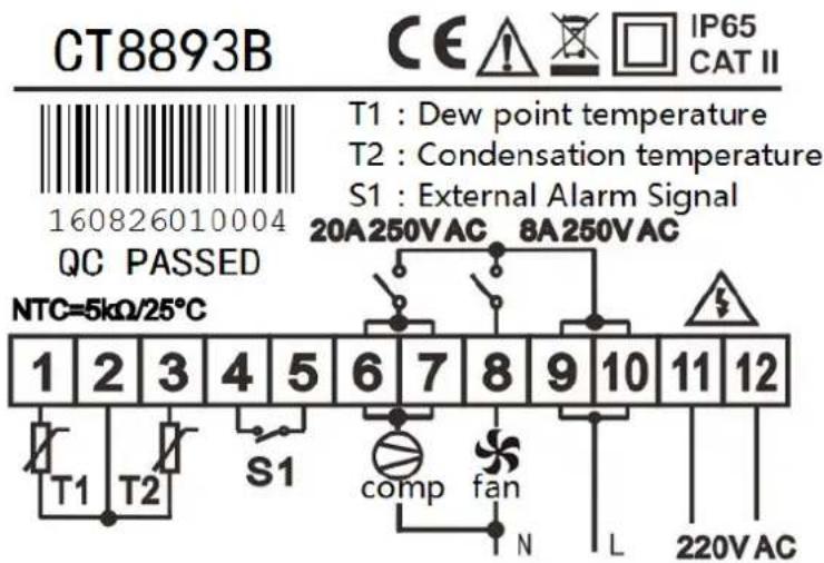
4. Notes
- Please use the temperature sensor allocated by our company.
- If compressor power is less than 1.5HP, can direct control by internal relay. Otherwise need to connect ac contactor.
● Fan loaded with no more than 200w.
Importer:
GENPOWER LTD
Isaac Way, London Road,
Pembroke Dock, UNITED KINGDOM, SA72 4RW
T: +44 (0) 1646 687 880 F: +44 (0) 1646 686 198
E: info@hyundaipowerproducts.co.uk
www.hyundaipowerproducts.co.uk
Imported/Distributed by Genpower Ltd for The United Kingdom & Ireland


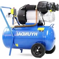

- SCREW AIR COMPRESSOR
- General Safety Notes.
- DANGER
- WARNING
- CAUTION
- NOTE
- Batteries (where present).
- Vibrations (where applicable).
- Noise (where applicable).
- MACHINE SPECIFIC SAFETY
- Introduction
- Description on the compressor
- Range of application
- Maintenance
- Guarantee
- Safety rules
- Technical modification
- Operating Principle
- Main Structures
- Pipeline Flow Diagrams
- Warnings and Announcements
- Power distribution for the machine
- Announcements
- Warning symbols
- Equipment Installations
- Installation site choosing and heat elimination and ventilation system
- Equipment Operation
- operation (Please refer to what is stated in item 7.2 in announcements)
- Air compressor can only be come into service when it is equipped with air storage tank(as what is shown in Table 1-Main Technical Data).
- Test run of the new machine
- Safety protection
- Operations and Maintenance
- Routine operation and maintenance (According to provisions in Table 5)
- Examining and maintaining before operation
- Starting up Checking
- Processing method of long-term shutdown
- Conveyor- type screw machine
- Directly-Connected Type Screw Machine
- SCREW AIR COMPRESSOR CONTROL USER
- OPERATING MANUAL
- NOTICE
- Features:
- Basic Operation
- Button Explanation
- Indicator instructions
- Display of status and operations
- Operating parameters
- User Parameter (Customer Parameter):
- Customer Parameter and Functions
- Factory Parameters
- Manufacturers and function
- Calibration parameters
- The operating authority and password
- Technical parameters and functions
- Type and specification
- Instruction of type
- Specification table for power of suited motor
- Installation
- Installation of transducer
- Controller Installation
- Terminal arrangement diagram
- Control principles
- Local Automatic control
- ②. Automatic operation control:
- ③. Manual loading/unloading under automatic status
- ④. Normal shutdown:
- ⑤. Control of preventing frequent starting
- Remote automatic control
- Local manual control
- Remote Manual Control
- Network control
- Temperature control of fan
- Failure shutdown and emergency shutdown
- Early-warning and prompts
- Indication of early warning of oil filter
- Indication of early warning for air filter
- Indication of early warning for oil separator
- Indication of early warning for lubricating oil
- Indication of early warning for grease
- Indication of early warning for belt
- High air temperature warning
- Controller protection
- Motor protection
- Gas Exhaust Over-temperature Protection
- Non-reversing Protection of Air Compressor
- Overpressure Protection of Pressure Supply
- Malfunction Protection of Sensor
- Removal of Common Failures
- Failures Review
- Air Dryer
- Notice item
- Installation
- Stop and run
- The fault and exclude way of the dryer
- Cannot start
- The AC contactor can pull but can not start and run
- Can start but stop a little late
- The gas is reduced or not by the compressed air
- The head frost
- Fault exclude
- Dryer Controller User Guide
- Technique Index
- Operating Guide
- Meaning of the LED display
- Temperature display
- Cumulative working hours display
- Higher level operation
- Basic Operating Principle
- Compressor control
- Fan control
- External alarm
- Command
- Wiring Diagram
- Notes
Brand : HYUNDAI
Model : HYSC100350D
Category : Compressor