
AL6-K01 - LED Lighting VAIS Technology - Free user manual and instructions
Find the device manual for free AL6-K01 VAIS Technology in PDF.


| Product Type | Wireless Keyboard |
| Model | AL6-K01 |
| Brand | VAIS Technology |
| Dimensions (W x D x H) | 43.5 x 12.5 x 2.5 cm |
| Weight | 520 g |
| Power Supply | 2 x AAA batteries (not included) |
| Wireless Range | Up to 10 meters |
| Connection | 2.4 GHz USB receiver |
| Key Layout | QWERTY with numeric keypad |
| Number of Keys | 104 |
| Compatibility | Windows, macOS, Linux |
| Functions | Multimedia keys, adjustable tilt, low battery indicator |
| Maintenance and Cleaning | Wipe with a soft, dry cloth; avoid liquid cleaners |
| Safety | Keep away from extreme heat; do not disassemble |
| Spare Parts and Repairability | Batteries replaceable; receiver available separately |
| General Information | Designed for quiet and comfortable typing |
Frequently Asked Questions - AL6-K01 VAIS Technology
User questions about AL6-K01 VAIS Technology
0 question about this device. Answer the ones you know or ask your own.
Ask a new question about this device
Download the instructions for your LED Lighting in PDF format for free! Find your manual AL6-K01 - VAIS Technology and take your electronic device back in hand. On this page are published all the documents necessary for the use of your device. AL6-K01 by VAIS Technology.
USER MANUAL AL6-K01 VAIS Technology
Installation & Operation Manual
natural_image
Illustration of a silver sedan with colorful abstract swirls around it (no text or symbols)LitLED
ambient lighting
AL6-K01
WHAT'S INCLUDED

natural_image
Coiled black cable with four labeled components (1-4) and a small inset image of an electrical component (no text or symbols on the main subject)1 ECU - Main Unit
2 Power & Input Harness
3 Mounting Bezel (x6)
4 Output Lens (x6)
BEFORE YOU START

WARNING
DO NOT BLOCK THE AIRBAG
Do not mount product or any added equipment where it can obstruct the operation of any safety devices such as the airbag.
DISTRACTION WARNING
Do not let product or any added equipment distract you while you are driving.

CAUTION
DO NOT ALLOW CABLES TO BECOME ENTANGLED IN SURROUNDING OBJECTS
Cables or wiring that obstruct or get caught on places such as the steering wheel, shift lever, brake pedals, etc. can be extremely hazardous.
DO NOT INSTALL IN LOCATIONS WITH HIGH MOISTURE OR DUST
Moisture or dust may result in product failure.
DISCONNECT THE NEGATIVE BATTERY TERMINAL
Before starting any installation work, you must wait 90 seconds after turning the ignition switch to the LOCK position and disconnecting the negative (-) terminal from the battery. The supplemental restraint system (airbag) is equipped with a backup power source. If installation work is started less than 90 seconds after disconnection of the negative (-) battery terminal, the SRS may deploy. VAIS Technology is not responsible for any vehicle settings lost due to a battery disconnect. Reference owner's manual for vehicle specific details.

natural_image
Close-up of a hand adjusting a small mechanical component with a red arrow indicating direction (no text or symbols visible)POWER HARNESS CONNECTIONS

Door Trigger / Dome Light (Orange) OPTIONAL FEATURE
WITH DOOR TRIGGER ACTIVE

ENTRY/EXIT LIGHT IS WHITE
SEE PG. 9 FOR SETTINGS
! DOOR TRIGGER / DOME LIGHT (+/-)
Device Default:
(12V+) Positive Input
Solid Orange wire is triggered with 12V Signal
For vehicles with (-) Negative Trigger:
Input can be set to (-) Negative.
Scan QR Code for details.
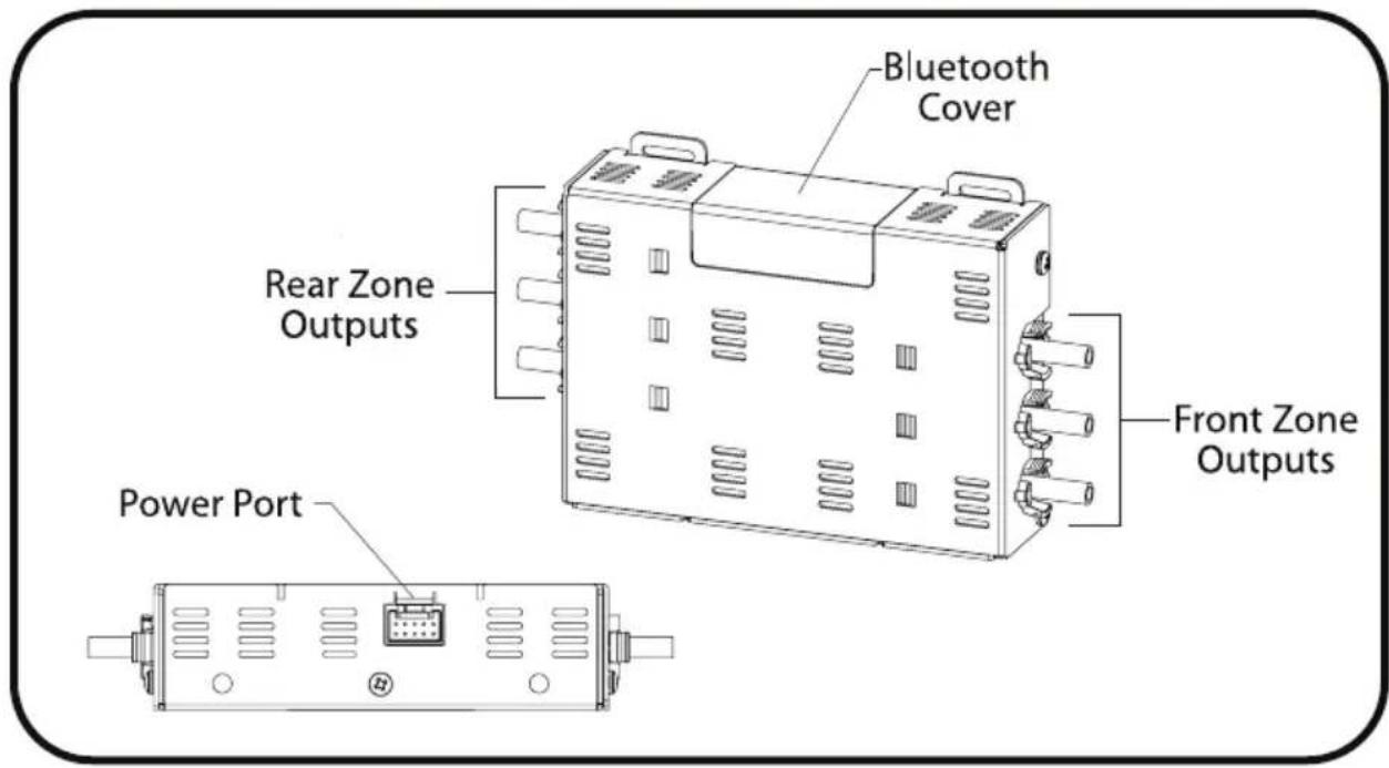
CONNECTORS AND PORTS
INSTALL THE ECU MODULE AND ROUTE THE FIBER OPTIC CABLES
1
Remove the interior panels where you want to install the lenses.

natural_image
Close-up of a red and black car seatbelt buckle (no text or symbols visible)2
Drill 8mm holes with a step drill bit. VAIS Recommends Irwin #11102.
Drill at a 90-degree angle to produce an even round hole.
* Thicker panels may require a larger opening

natural_image
Close-up of a black plastic clip inserted into a gray surface, with no visible text or symbols.3
Do not bend the fiber optic cables closer than 4 inches from the ECU.

Gently bend cable

natural_image
Hand holding a black cable with a coin for scale, overlaid with a green checkmark (no text or symbols on the cable or background)Do not over bend

SECURE THE MODULE

natural_image
Close-up of a mechanical component with highlighted areas and arrows, no visible text or symbolsSecure the ECU Module, as shown, use zip ties and mounting tabs.
Make sure to mount the ECU Module with plastic cover facing up.

Keep plastic cover away from large metal plates. Mount the module to a structure as shown. DO NOT mount to wiring harnesses, etc.
INSTALL BEZELS AND LENSES
1
Install bezel into the hole that was drilled.

natural_image
Close-up of a metallic surface with a circular hole and curved edge (no text or symbols visible)2
Route the fiber optic through the bezel.
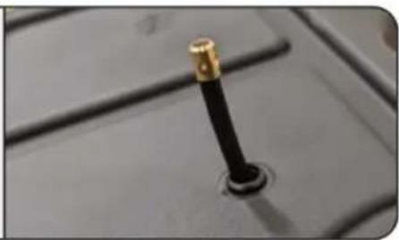
natural_image
Close-up of a black and gold mechanical lever handle on a gray surface (no text or symbols visible)3
Install lens on the end of the fiber optic cable.
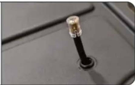
natural_image
Close-up of a black cable with a metallic connector inserted into a socket (no visible text or symbols)4
Push the fiber optic cable with the lens into the bezel, pushing in until it clicks into the bezel.

Do not damage the lens. Guide it directly into the bezel and do not bend the ends of the lens.

natural_image
Close-up of a metallic screw head with a circular hole, no text or symbols visible* Repeat these steps for each fiber optic cable.
DISASSEMBLING THE OUTPUT SIDE
1
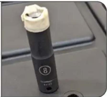
Use an 8mm socket and wrap the end in protective tape.

Protective tape is required to protect the bezel from getting scratched by the 8mm socket.
natural_image
Close-up of a black cylindrical device with a white lid and number 8, mounted on a gray surface (no visible text or symbols)2
Press 8mm socket firmly against the bezel.

natural_image
Close-up of a finger pressing a black cable with white adhesive tape (no text or symbols visible)3
Push the fiber optic cable in the direction shown, until the lens comes out.

natural_image
Close-up of a hand holding a black tool with a blue arrow pointing to a small object, no visible text or symbols.4
Remove the lens from the fiber optic cable, Pull the cable out of the hole.

natural_image
Close-up of a black cable with a metallic connector inserted into a dark socket (no text or symbols visible)DOWNLOAD & OPEN THE APP

natural_image
Illustration of a silver car with colorful abstract swirls surrounding it (no text or symbols)LitLED
ambient lighting

Download on the App Store

GET IT ON Google Play

SELECT THE DEVICE
Select the LitLED device to start using the app.
Troubleshooting
If LitLED device does not appear: Turn vehicle illumination OFF/ON
If LitLED app does not connect to the module: Reboot the phone.
If ECU is inactive for over 5 minutes it will go to sleep mode. To wake up, Open/Close the Door or turn illumination OFF/ON
VEHICLE ILLUMINATION
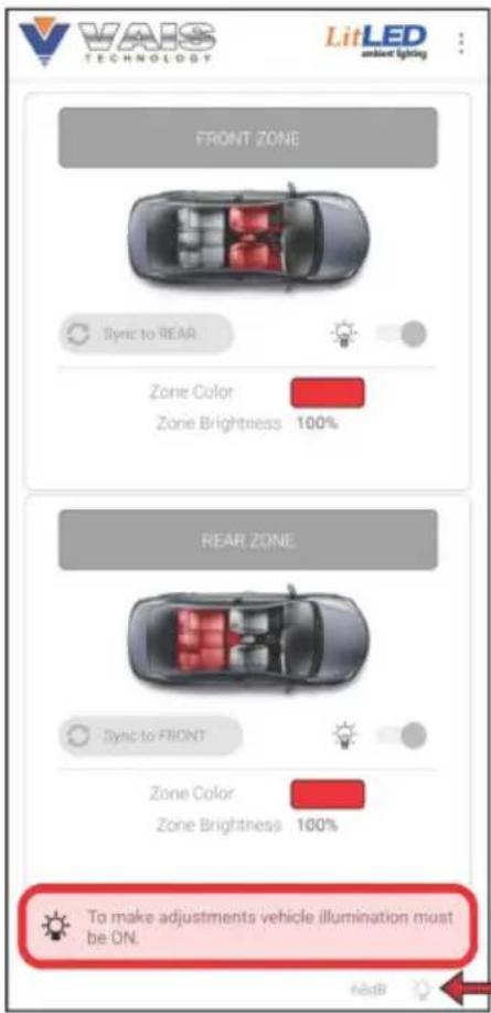
WHEN VEHICLE'S ILLUMINATION IS OFF
App buttons are Gray, and will not function

Illumination indicator at the bottom of the app screen will be Gray.

App will not work while Door Trigger is active. To change Door Trigger settings see Pg. 9

Icon will appear when Door Trigger is active.
Illumination Indicator OFF
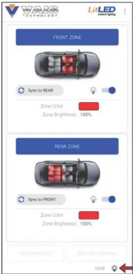
WHEN VEHICLE'S ILLUMINATION IS ON
App buttons will illuminate Blue, and will now function.

Illumination icon will light up at the bottom of the screen.
SELECT A ZONE TO CHANGE THE COLOR

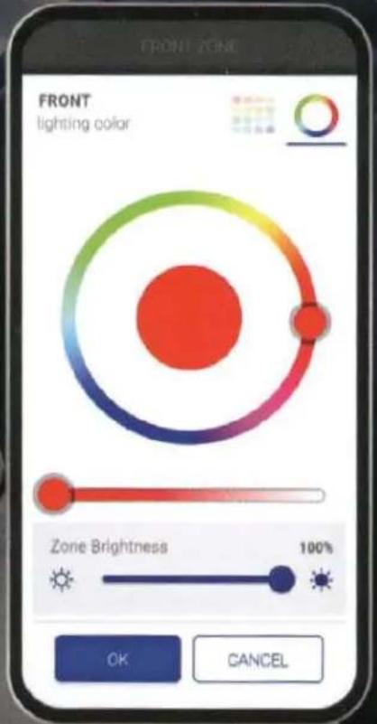
CHOOSE COLOR AND BRIGHTNESS


ATTENTION INSTALLERS
Run Diagnostic Mode prior to assembly
DIAGNOSTIC MODE
Verify the proper operation of each zone and channel as the app goes through the diagnostic mode.
AL6-K01 unit will cycle through each of the primary colors to verify LED functionality.

Diagnostic mode will be interrupted if application switches to background mode.
Diagnostic mode will start over after application returns to foreground mode.

ENTRY/EXIT LIGHT SETUP
Select Positive or Negative input for dome light
Timer for Entry Light when door is open
Timer for Entry Light when door is closed
Set the Dimming Speed for entry light
Set the Front Zone brightness for entry light
Set the Rear Zone brightness for entry light
Toggle Front Zone (ON/OFF)
Toggle Rear Zone (ON/OFF)
Troubleshooting Guide
| Symptom | Check |
| No illumination from interior light by the shifter | 1. Turn headlights ON.2. Check and verify harness connection. |
| LitLED app doesn't connect to module | 1. Turn headlights ON/OFF.2. Reboot the phone. |
| No illumination from interior ambient light, all sources | 1. Turn headlights ON.2. Light is turned off in the app.3. ECU internal temp 65C (149F) and needs to cool down. 🎨* will be displayed.4. Check and verify harness connection |
| One or more (not all) light sources do not have the light | 1. Light is turned off in the app for one or more zones.2. Check and verify fiber optics cable connection at ECU and Bezel.3. Make sure fiber optic cable isn't bent more than 30mm radius. |

WARNING
DO NOT DISASSEMBLE OR ALTER THE MODULE
Doing so may result in an accident, fire, or electric shock.
USE ONLY SPECIFIED ACCESSORY PARTS
Use of other than specified parts may damage product internally.
FOLLOW THE OPERATIONAL AND INSTALLATION MANUALS
YOU SHOULD READ AND FAMILIARIZE YOURSELF THOROUGHLY WITH THE FOLLOWING INFORMATION PRIOR TO INSTALLING AND USING THIS UNIT. IN ADDITION, YOU MUST CAREFULLY READ AND FOLLOW THE INSTALLATION SCHEMATICS/INSTRUCTIONS FOR THE PRODUCT AND THE VEHICLE IN WHICH IT IS BEING INSTALLED. FAILURE TO FOLLOW INSTALLATION INSTRUCTIONS MAY DAMAGE THE PRODUCT AND THE VEHICLE, WILL VOID THE PRODUCT WARRANTY, AND MAY VOID THE VEHICLE WARRANTY.
FCC WARNING
Contains FCC ID:2APD9-RSL10SIP
This device complies with Part 15 of the FCC Rules. Operation is subject to the following two conditions:
(1) This device may not cause harmful interference, and (2) this device must accept any interference received, including interference that may cause undesired operation.
Any changes or modifications not expressly approved by On Semiconductor could void the user's authority to operate the equipment.
LIABILITY DISCLAIMER
VAIS Technology can not be held liable for damages or injuries caused by, or resulting from use of this guide. Strictly adhere to all car manufacturer warnings that pertain to the disassembly, maintenance, or servicing of the vehicle and any of its associated part systems. VAIS Technology can not be responsible for discrepancies, or inconsistencies that may occur due to automobile manufacturing changes.
TROUBLESHOOTING
Should this product fail to operate properly, please contact your Dealer or our Customer Service Department at sales@vaistech.com
Warranty is available for download: https://www.vaistech.com/download/15244
To request a paper warranty copy please contact us:
VAIS Technology
Warranty Department
8811 American Way
Unit 125
Englewood, CO 80112
720-733-2348
sales@vaistech.com

VAIS Technology is not responsible for or liable for any installation cost, property loss, damages whatsoever, including but not limited to, any consequential damages, incidental damages, loss of time, loss of earnings, commercial loss, loss of economic opportunity and the like that may or may not be resulted from the operation of the VAIS Technology product(s). Manufacturer does offer a limited warranty to replace or repair the control module. See Warranty for more information.
This Vehicle is Equipped with Interior Ambient Lighting

natural_image
Illustration of a silver sports car with colorful motion trails (no text or symbols)LitLED
ambient lighting

GET IT ON
Google Play


Download on the
App Store

DOWNLOAD THE APP & SELECT DEVICE


SELECT BRIGHTNESS & COLOR FOR EACH ZONE

- LitLED
- WHAT'S INCLUDED
- BEFORE YOU START
- WARNING
- DO NOT BLOCK THE AIRBAG
- DISTRACTION WARNING
- CAUTION
- DO NOT ALLOW CABLES TO BECOME ENTANGLED IN SURROUNDING OBJECTS
- DO NOT INSTALL IN LOCATIONS WITH HIGH MOISTURE OR DUST
- DISCONNECT THE NEGATIVE BATTERY TERMINAL
- ! DOOR TRIGGER / DOME LIGHT (+/-)
- INSTALL THE ECU MODULE AND ROUTE THE FIBER OPTIC CABLES
- 1
- 2
- 3
- SECURE THE MODULE
- INSTALL BEZELS AND LENSES
- 4
- DISASSEMBLING THE OUTPUT SIDE
- DOWNLOAD & OPEN THE APP
- ambient lighting
- SELECT THE DEVICE
- Troubleshooting
- VEHICLE ILLUMINATION
- WHEN VEHICLE'S ILLUMINATION IS OFF
- WHEN VEHICLE'S ILLUMINATION IS ON
- ATTENTION INSTALLERS
- DIAGNOSTIC MODE
- ENTRY/EXIT LIGHT SETUP
- DO NOT DISASSEMBLE OR ALTER THE MODULE
- USE ONLY SPECIFIED ACCESSORY PARTS
- FOLLOW THE OPERATIONAL AND INSTALLATION MANUALS
- FCC WARNING
- LIABILITY DISCLAIMER
- This Vehicle is Equipped with Interior Ambient Lighting
- DOWNLOAD THE APP & SELECT DEVICE
- SELECT BRIGHTNESS & COLOR FOR EACH ZONE
Brand : VAIS Technology
Model : AL6-K01
Category : LED Lighting