
TNG1S - Générateur de son Bogen - Free user manual and instructions
Find the device manual for free TNG1S Bogen in PDF.


| Product Type | Paging Amplifier |
| Brand | Bogen |
| Model | TNG1S |
| Dimensions (W x H x D) | 12 x 3 x 8 inches |
| Weight | 5 lbs |
| Power Supply | 120V AC, 60Hz |
| Output Power | 25W RMS |
| Inputs | Microphone, Line In |
| Outputs | Speaker (4Ω, 8Ω, 70V/100V) |
| Controls | Volume, Tone, Priority Paging |
| Operating Temperature | 0°C to 40°C |
| Protection | Short Circuit, Overload |
| Maintenance | Clean with dry cloth |
| Safety | Unplug before cleaning; avoid water |
| Spare Parts | Contact Bogen support |
| Repairability | Authorized service only |
Frequently Asked Questions - TNG1S Bogen
User questions about TNG1S Bogen
0 question about this device. Answer the ones you know or ask your own.
Ask a new question about this device
Download the instructions for your Générateur de son in PDF format for free! Find your manual TNG1S - Bogen and take your electronic device back in hand. On this page are published all the documents necessary for the use of your device. TNG1S by Bogen.
USER MANUAL TNG1S Bogen
TNG1S
Tone Generator Module
Features
- Select from burst/steady, slow whoop, siren, mechanical bell, Klaxon, night ringer, double chime, and doorbell tones
- Select 4 of 8 tones to trigger
• Momentary and continuous playback modes - Screw terminal for 4 external trigger connections
- Level control
- Microprocessor-controlled operation
• 4 levels of available priority - Can be muted from higher priority modules
- Can mute lower priority modules
Module Installation
WARNING:
Turn off power to unit and make all jumper selections before installing module in unit.
- Turn off all power to the unit.
- Make all necessary jumper selections.
- Position module in front of any desired module bay opening, making sure that the module is right-side up.
- Slide module on to card guide rails. Make sure that both the top and bottom guides are engaged.
- Push the module in to the bay until the faceplate contacts the unit's chassis.
- Use the two screws included to secure the module to the unit.
Connections
Connect a contact closure between any of the “T” labeled terminals and the COM terminal to trigger a tone playback. An open collector type output can also trigger operation. A ground from the open collector triggering device must be connected to the COM terminal to complete the conduction path.
Playback modes
One Time
When a trigger is applied and removed before the tone's playback cycle finishes, the tone will play only that one time and stop. A momentary trigger must be present for at least 10 ms to ensure that the TNG1S will recognize it and no other tone can be playing when the trigger pulse is applied since the module ignores other triggers applied during tone playback.
Continuous
To cause continuous play of a tone, the trigger must be applied for the entire time during which the tone is to play. Continuous play of a tone is actually a retriggering of the one time tone cycle again and again. At the end of a tone's playback cycle, the TNG1S will recheck the status of this tone's trigger. If it detects a trigger, it immediately retriggers the tone and causes it to play again. This process continues until the trigger is removed. Once the trigger is removed, the tone will finish its current tone cycle and stop. Some of the tones contain short pauses between tone playbacks to make them sound proper when played as a continuous train. A very short break in playback will occur during continuous operation of the mechanical bell and 512 Hz steady tones.
Trigger operation
There is no priority structure assigned to the different trigger inputs. Triggering is on a first-come, first-serve basis. The internal microprocessor constantly scans the 4 trigger inputs for activity and responds to the first trigger it detects as active. Once a tone is triggered, it takes control of the module operation. All other triggers applied during the tone playback cycle will be ignored. Once a tone has stopped, the microprocessor continues scanning through the trigger inputs until it detects another trigger and begins playback of that tone.

flowchart
graph TD
    A["512 Hz Steady"] --> B["PRIORITY LEVEL"]
    B --> C["1 (Highest)"]
    B --> D["2"]
    B --> E["3"]
    B --> F["4 (Lowest)"]
    C --> G["A"]
    D --> H["B"]
    E --> I["C"]
    F --> J["D"]
    G --> K["A"]
    H --> L["B"]
    I --> M["C"]
    J --> N["D"]
    K --> O["A"]
    L --> P["B"]
    M --> Q["A"]
    N --> R["B"]
    O --> S["C"]
    P --> T["B"]
    Q --> U["A"]
    R --> V["B"]
    S --> W["C"]
    T --> X["B"]
    U --> Y["A"]
    V --> Z["B"]
    W --> AA["C"]
    X --> AB["B"]
    Y --> AC["C"]
    Z --> AD["A"]
    AA --> AE["B"]
    AB --> AF["C"]
    AC --> AG["B"]
    AD --> AH["C"]
    AE --> AI["A"]
    AF --> AJ["B"]
    AG --> AK["C"]
    AH --> AL["B"]
    AI --> AM["C"]
    AJ --> AN["B"]
    AK --> AO["C"]
    AL --> AP["B"]
    AM --> AQ["C"]
    AN --> AR["B"]
    AO --> AS["C"]
    AP --> AT["C"]
    AQ --> AU["C"]
    AR --> AV["C"]
Jumper Selections\*
Tone Selection
The TNG1S provides a menu of 8 tones; of which 4 can be selected to be triggered from the terminal strip. Place up to 4 jumper shunts at the lettered position that corresponds to the desired tones (use Tone Selection Table above). The tones will be assigned to the trigger terminals in the order they fall into from A to H where the first tone selected on the way from A to H is assigned to T1, the next tone selected is assigned to T2, and so on. If more than 4 tones are selected, only the first 4 (from A to H) are assigned to the terminal strip. If less than 4 tones are selected, then only the terminals needed to correspond to the number of tones will be operational.
Priority Level\*\*
This module can respond to 4 different levels of priority. Priority 1 is the highest priority. It mutes modules with lower priorities and is never muted. Priority 2 can be muted by Priority 1 modules and mutes modules set for 3 or 4. Priority 3 is muted by either Priority 1 or 2 modules and mutes Priority 4 modules. Priority 4 modules are muted by all higher priority modules. If the TNG1S is muted by a higher priority while it is playing a tone, it will abort that tone playback. If the trigger is still active when the TNG1S is unmuted, the tone will begin playing from the beginning. If the trigger is not active, the TNG1S will resume scanning the terminal triggers for activity.
Bus Assignment
Certain Bogen products that accept input modules contain two mix buses. In these products, the Bus Assignment jumpers can be arranged so that the tones are fed to either or both buses. On single bus products, both bus outputs are tied together. In this case assigning the output to either or both buses provides the same operation. Using the “Both” jumper arrangement is recommended for these systems.
* Markings on circuit board may differ; use diagram above as reference for jumper settings.
**The number of priority levels available is determined by the amplifier the modules are used in.
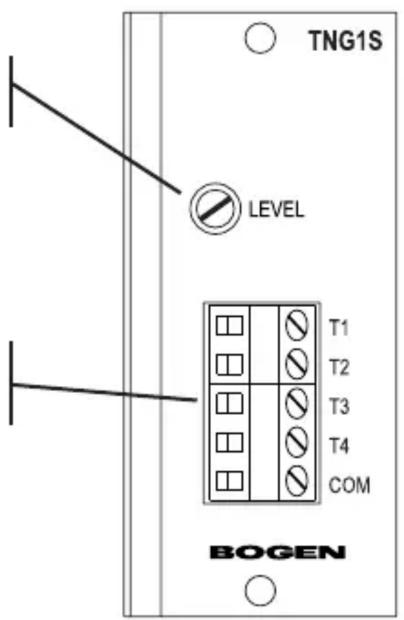
Front Panel Callouts
Level Controls
Controls output level of module tones.
Tone-Trigger Terminal Strip
External contact closures that are connected here trigger tone playback.
Block Diagram

flowchart
graph LR
    COM["COM"] --> MICROPROCESSOR["MICROPROCESSOR CONTROLLED TONE GENERATOR"]
    MICROPROCESSOR --> GAIN["GAIN"]
    MICROPROCESSOR --> MUTING["MUTING"]
    GAIN --> BUS_A["BUS A"]
    GAIN --> BUS_B["BUS B"]
    MUTING --> BUS_A
    MUTING --> BUS_B
    PRIORITY["Priority Level"] --> MUTEOUT["MUTE OUT"]
    PRIORITY --> MUTEIN["MUTE IN"]
    MUTEOUT --> MUTEHIGH["MUTE HIGH"]
    MUTEOUT --> MUTEMED["MUTE MED"]
    MUTEIN --> MUTELOW["MUTE LOW"]
    A["A"] --> TONESelection["TONE SELECTION"]
    B["B"] --> TONESelection
    C["C"] --> TONESelection
    D["D"] --> TONESelection
    E["E"] --> TONESelection
    F["F"] --> TONESelection
    G["G"] --> TONESelection
    H["H"] --> TONESelection
Brand : Bogen
Model : TNG1S
Category : Générateur de son