VT-SHE904 - VCR Vitek - Free user manual and instructions
Find the device manual for free VT-SHE904 Vitek in PDF.


| Product Type | VCR (Video Cassette Recorder) |
| Brand | Vitek |
| Model | VT-SHE904 |
| Dimensions (Approx.) | 430 x 275 x 95 mm |
| Weight (Approx.) | 3.5 kg |
| Power Supply | 220-240V, 50Hz |
| Power Consumption | 20 W (typical) |
| Video System | VHS (NTSC/PAL/SECAM compatible) |
| Record/Playback Formats | VHS SP, LP, EP modes |
| Heads | 4-head helical scan system |
| Audio | Monaural (1 channel) |
| Key Functions | Play, Record, Rewind, Fast Forward, Stop, Pause/Still, Eject, Timer Recording |
| Front Panel | VCR controls, cassette compartment, infrared receiver, buttons for tracking, channel, input select |
| Connections | RF in/out (75 ohm), Audio/Video RCA in/out (composite), S-Video out (optional) |
| Tuner | Built-in analog TV tuner (VHF/UHF) |
| Recording Timer | Programmable up to 8 events over 1 month |
| Remote Control | Infrared, includes number pad, transport controls, menu |
| Maintenance | Periodic cleaning of video heads using head cleaning cassette recommended |
| Safety Precautions | Do not expose to moisture; avoid inserting objects; use on stable surface; unplug during storms |
| Spare Parts | Remote control, power cord, RF cable, cleaning cassette (if included) |
| Reparability | Refer to qualified service center; internal parts not user-serviceable |
| User Manual | Available for download in PDF from notice-facile.com |
Frequently Asked Questions - VT-SHE904 Vitek
User questions about VT-SHE904 Vitek
0 question about this device. Answer the ones you know or ask your own.
Ask a new question about this device
Download the instructions for your VCR in PDF format for free! Find your manual VT-SHE904 - Vitek and take your electronic device back in hand. On this page are published all the documents necessary for the use of your device. VT-SHE904 by Vitek.
USER MANUAL VT-SHE904 Vitek
natural_image
Exterior view of two black VITEK and SpireHD audio equipment units (no visible text or symbols on the devices themselves)FEATURES
• Supports High Resolution HD-TVI, AHD, and 960H Cameras
• 4, 8, or 16 Video Inputs with 1 HDMI, 1 Spot Monitor Output (VT-SHE904) / 1 HDMI, 2 Spot Monitor Output (VT-SHE908/VT-SHP916) and 1 VGA output
• H.264 Compression
• Realtime with up to 480fps Live Display & 480fps Recording (VT-SHP916) / 240/240 (VT-SHE908) / 120/120 (VT-SHE904)
• Supports both Dynamic and Static IP Addresses
• 16 Audio In / 2 Audio Out (VT-SHP916) / 4 Audio In / 1 Audio Out (VT-SHE904/VT-SHE908)
- 18 Alarm Inputs (16 +1 Panic & 1 Reset) 8 Outputs with 8 Relays (VT-SHP916) / 6 Alarm Inputs (4 +1 Panic & 1 Reset) with 2 Relays (VT-SHE904/VT-SHE908)
- Remote Viewing over the Internet via Web Browser or LAN
- Up to Five internal 6TB HDD for up to 30TB of internal Storage (VT-SHP916) / 4 internal HDD (VT-SHE908) / 2 internal HDD (VT-SHE904)
• Supports 6TB Hard Drives
- Applications for iPhone, iPad, iTouch and Android Devices
- "Quick Search" Function for automatic review
• Dual Gigabit Ethernet Ports (1 LAN + 1 WAN)
• Mac OSX Client & CMS Central Management Software Included
• Automatic sending of Health & Event notifications via email
• Control locally via Front Panel Controls, USB Mouse or with the Included IR Remote control
• PTZ Control over RS-485
- Rack Mountable
Copyright
This manual without the manufacturer's approved copy and reprinted partially or in full, or translated into another language is prohibited.
Limitation of Liability
This product is designed to prevent fire and theft is not the main means. We shall not be liable for accidents or damage by using this product can result in liability for accidents or damage
In order to improve the performance of the product without prior notice to the product may be a firmware upgrade.
Content
OVERVIEW
4
4 Safety Instruction
5 Key Features
6 What's included
7 Rear Panel
9 Remo te Control At a Glance
PLAY
83
83 If you want to play
INSTALLATION
11
11 Replacing HDD
16 Basic Layout
17 Connecting to an external device
ARCHIVING
86
86 To start the Archive menu
MONITORING
23
25 Live Screen At a Glance
WEB VIEWER
89
89 What is the Web Viewer?
91 Live
95 Search
98 Setup
SYSTEM SETTING
32
32 To move to the System Setup menu
33 Camera Setting
39 Display Setting
47 Audio Setup
48 User Setting
50 Network Setup
53 System Setting
59 Storage
63 Event Setup
MOBILE VIEWER
118
118 nViewer
RECORD SETTING
72
72 To start the Record Setup menu
73 Record Setup
ARCHIVE VIEWER
133
133 Getting started with the Backup Player
135 Backup Player At a Glance
SEARCH
78
78 To move to the Search menu while in monitoring
78 To move to the Search menu while in playback mode
79 Search Settings
APPENDIX
138
138 Compatible HDD Specifications
139 Troubleshooting (FAQ)
140 Open Source License Report on the Product
Safety Instruction
This product was tested with a UPS to satisfy EN 61000-4-11 test conditions (voltage dips and short interruptions test) under the EN 50130-4: 2011 standard.
The Company shall not have any responsibility for any accident or damage that may incur during the use of the product. For your safety, we provide a few instructions about installation, manipulation, cleaning, assembly/disassembly of the product as below. So please read carefully and comply with the instructions.
Before installation
Comply with the following instructions to prevent a fire, explosion, system failure or electric shock.
- Remove the power supply module before proceeding.
- Check the input voltage (AC100V–AC240V) to the power supply module before connecting it.
- Keep the product away from humidity.
- Ensure that all devices connected to the product should be properly earth-grounded.
In operation mode
Comply with the following instructions to prevent a fire, explosion, system failure or electric shock.
- If you need to open the cover, consult with a service person who could help you do what you want to do.
- Do not connect multiple devices to a single power socket.
- Keep the product away from dust or too much combustible substances (ex: propane gas).
- Do not touch it with wet hand.
- Do not insert a conductor in the vent of the ventilation system.
- Do not apply excessive force to unplug the power cord.
Disassembly & Cleaning
- When cleaning on the surface, use a dry cloth.
- Do not wipe the product using water, paint thinner or organic solvents.
- Do never dismantle, repair or modify the product by your own.
During installation
To prevent an accident or physical injury and to operate DVR properly, please comply with the followings:
- Secure at least 18 centimeter of distance between cooling fan and wall for a proper ventilation.
•Install the product on a flat surface. - Keep it away from direct sunlight or excessive temperature.
While in use
- Do not apply force to or shake it while using it.
- Do not move, throw away or put excessive force to it.
- Using any unrecommended HDD may cause a system failure. Check the compatibility list and use only compatible HDDs.
{A system failure or data loss caused by an incompatible HDD will void your warranty.}
CAUTION
Replaceable batteries
Risk of Explosion if Battery is replaced by an Incorrect Type. Dispose of Used Batteries According to the Instructions.
Warning to service personnel
Double pole/neutral fusing
Ethernet Instruction
This equipment is indoor use and all the communication wiring are limited to inside of the building or similar word.
Key Features
This product is capable of receiving inputs from up to 16 channels of 1080P camera inputs of video and audio and recording onto a hard disk drive in real-time, as well as providing monitoring, playback and backup footages in excellent quality of 1080P resolution.
It also provides transferring video and audio data to the networked external devices, which allows remote monitoring environment for computers and mobile devices including cell phones.
- Up to 16 channels of 1080P camera video can be displayed at 480 fps / 400 fps in real time
- Up to 16 channels of 1080P camera videos can be saved at maximum 480 (NTSC) / 400 (PAL) fps.
- Simultaneous recording and playback of maximum 16 channels (at 480 fps @ D1)
•Supports H.264 HP (High Profile) CODEC - Auto alarm feature with self-diagnostics on the system (HDD S.M.A.R.T, system temperature, network error, FAN error, etc.)
•Supports dual streaming for remote access service
•Supports HDD extension (eSATA) - Various search methods (time, event, bookmark, thumbnail and text-in)
•Mass storage backup via USB port or FTP server
•Supports remote access and search using web browser
•Dedicated smart phone applications that can be used with iPhone and iPad or on Android OS
•1080p Full HD GUI
What's included
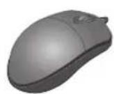
natural_image
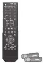
Black remote control with buttons and two batteries (no visible text or symbols)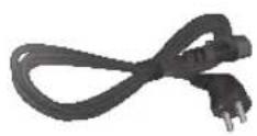
Mouse x1 Remote Control x1 & Batteries (AAA x2) Power Cable x1
natural_image
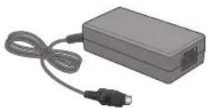
Exterior view of a gray rectangular electronic device with a black connector and coiled cable (no text or symbols visible)
natural_image
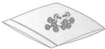
Illustration of a layered document or sheet with abstract molecular-like figures (no text or symbols)DC 12V Adaptor x1 (120W) Adapter cable retainer clip x1 Screws (For fixing HDD / ODD)
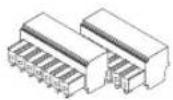
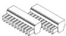

Terminal Blocks (7P) Terminal Blocks (10P / for 16 channel x4) CUSHION PAD

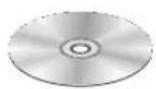
Quick Guide User manual CD
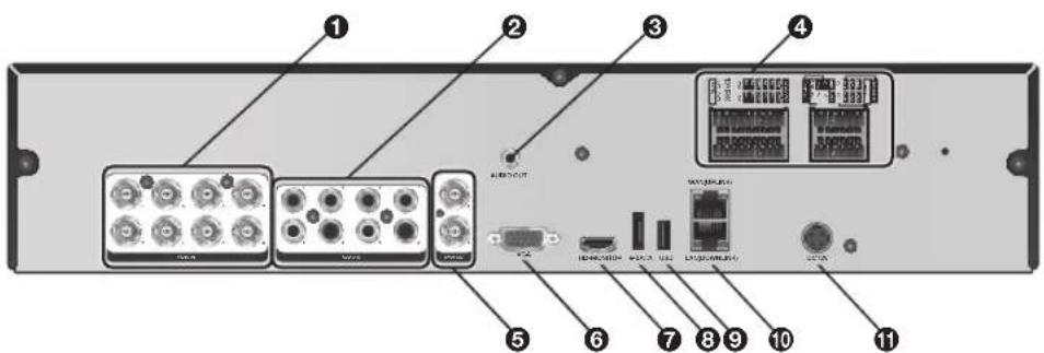
Rear Panel
8 channels
16 channels
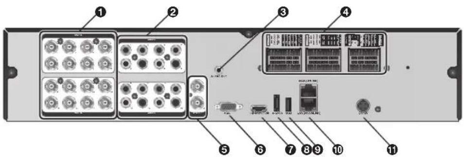
No. Name Description
| 1 | VIDEO IN Video input terminal for cameras. | |
| 2 | AUDIO IN Port for audio input. | |
| 3 | AUDIO OUT Port for speaker connection. | |
| ALARM IN Alarm input signal port. | ||
| ALARM OUT Alarm out signal port. O.C. (Pulled up to 5V via 10KOhm) | ||
| 4 | RELAY Relay Terminal output port. | |
| RS485 Ports for communication with external devices such as PTZ camera and system keyboard. | ||
| RS232 | Connection ports for signal cables to external devices such as PTZ camera, POS and ATM devices. | |
| 5 | SPOT OUT Exclusive port for SPOT output only. (Connect to a TV monitor.) | |
| 6 | VGA VGA monitor video output port. | |
| No. | Name Description | |
| 7 | HD-MONITOR HD monitor video output port. | |
| 8 | e-SATA Connection port for external eSATA storage. | |
| 9 | USB Used for connecting USB storage or mouse. | |
| 10 | WAN(UPLINK) Network port for connection to the Internet, router or hub. | |
| LAN(DOWN LINK) | Port for connecting the dedicated network device.√ Do not share it with other device. | |
| 11 | DC12V Power input port. | |
Remote Control At a Glance
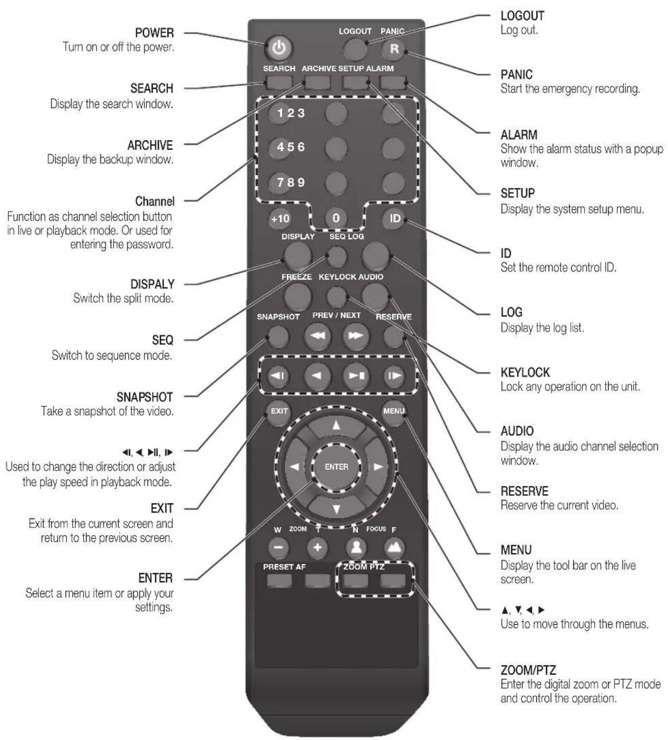
Change the remote control ID
The remote control will be active only if the remote control ID matches with that specified on the DVR.
If multiple DVRs are installed on one place and you have just a single remote control, use the ID button to set the remote control ID. Only the ID-matching DVR can be controlled.
- From
- under the System Setup menu, set the and press .
Select between 00 and 99. For more details, refer to. - Press the [ID] button on the remote control. The default remote control ID is 00.
- Use the number buttons to provide a two-digit ID. If you want to enter 01, for instance, enter the number 0 and 1 in sequence.
Check if the remote control ID is set properly by manipulating the remote control. - To reset the ID to 00, press and hold the [ID] button.
Replacing HDD
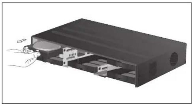
When an HDD is full or problematic, you can replace it with a new one by yourself.
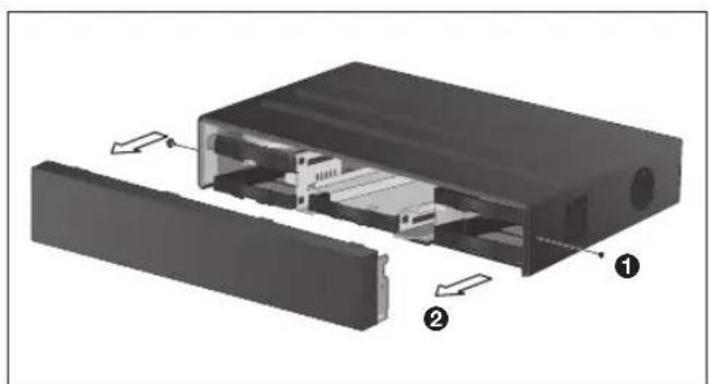
8 / 16Ch Model
√ Below illustrations are based on the 8/16-channel model.
- Remove 2 screws on both ends of DVR.
- Pull the front side of the unit forward to separate it.
natural_image
Exploded view diagram of a device showing internal components and labeled parts (no text or symbols present)- Hold the middle of HDD bracket's handle with index finger and pull it forward while sustaining the bracket handle with your thumb and middle finger as shown in the illustration.
natural_image
Illustration of a computer case with a hand inserting a component into the case (no text or symbols visible)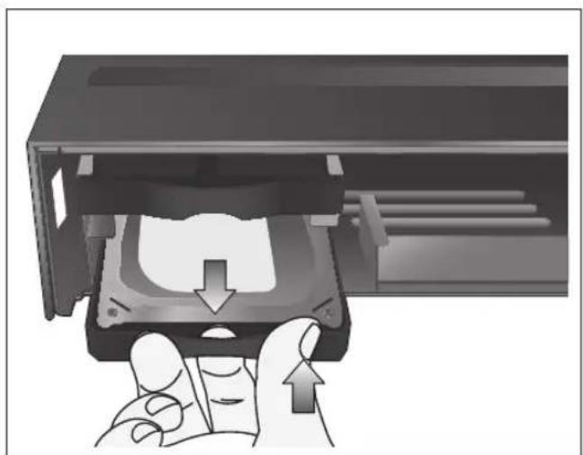
natural_image
Hand inserting a CD into a drive into a memory compartment (no text or symbols visible)
Installation
- Once the HDD bracket is separated from the main unit, remove 4 screws on both ends of HDD bracket to separate the HDD from the bracket.
- Install a new HDD and fasten 4 screws back to both ends of the bracket to fix it.
√ When installing HDD, make sure to install in the correct direction.
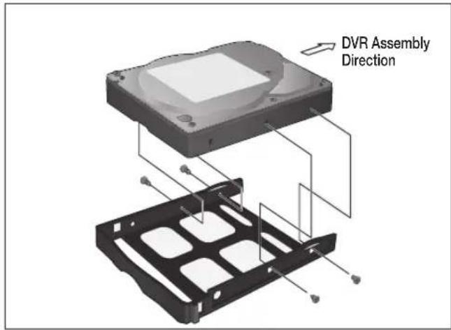
- Push the bracket installed with new HDD back into the main unit until it is completely inserted.
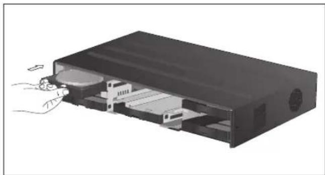
natural_image
Illustration of a computer drive with a hand inserting a component into the case (no text or symbols visible)- Hold center of the ODD bracket's holder by your index finger and pull it.
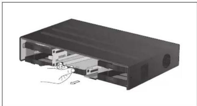
natural_image
3D illustration of a computer case with internal components and a hand inserting a cable (no text or symbols)- Install the ODD on the ODD bracket and fix it by fastening 4 screws on the bottom of it.
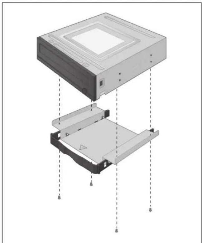
natural_image
Diagram of a computer drive with internal components and mounting holes (no text or symbols)- Insert the bracket with ODD into the main unit, push it until it's fully inserted.
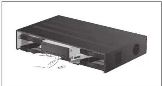
natural_image
3D rendering of a black electronic device casing with internal components and a hand inserting a cable (no text or symbols visible)- Assemble the front panel back to the unit.
When assembling the front panel to the main unit, make sure the marked part is tightly attached.
- Fasten 2 screws on both ends of the main unit.
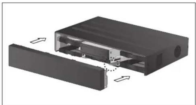
natural_image
3D diagram of an electronic device showing internal components and external casing (no text or symbols): Installation
If installed 5 HDD drives
√ Below illustrations are based on the 8/16-channel model.
7 Remove 2 screws on both ends of DVR.
2. Pull the front side of the unit forward to separate it.
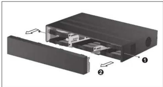
natural_image
Exploded view diagram of a device showing internal components and housing (no text or symbols)- Hold the middle of HDD bracket's handle with index finger and pull it forward while sustaining the bracket handle with your thumb and middle finger as shown in the illustration.
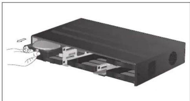
natural_image
Illustration of a computer drive with a hand inserting a cable into the internal compartment (no text or symbols visible)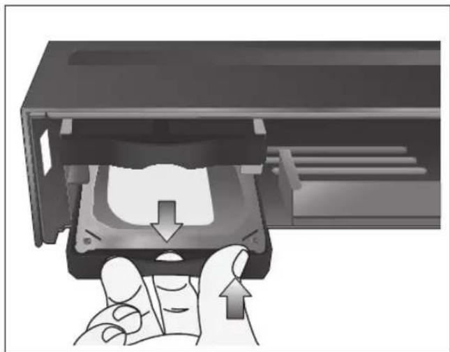
natural_image
Hand inserting a CD into a drive into a memory compartment (no text or symbols visible)-
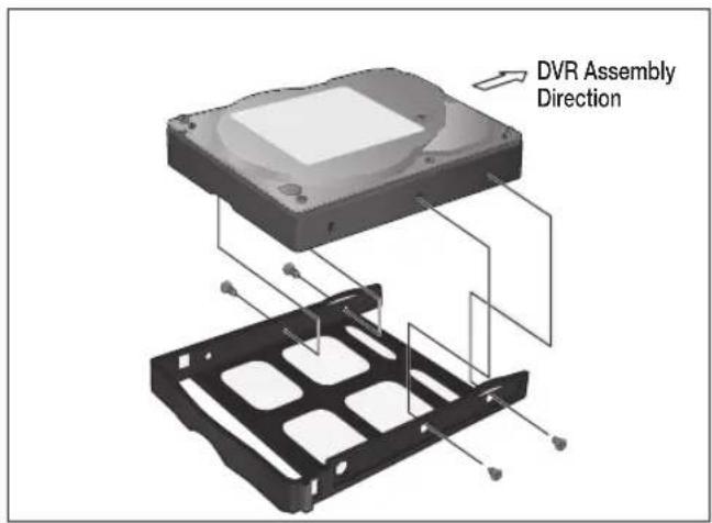
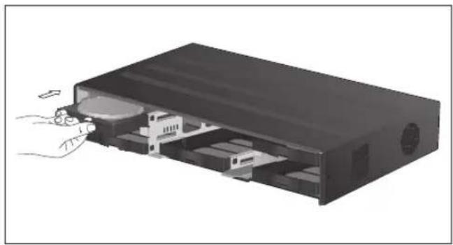
Once the HDD bracket is separated from the main unit, remove 4 screws on both ends of HDD bracket to separate the HDD from the bracket.
-
Install a new HDD and fasten 4 screws back to both ends of the bracket to fix it.
√ When installing HDD, make sure to install in the correct direction.
- Push the bracket installed with new HDD back into the main unit until it is completely inserted.
natural_image
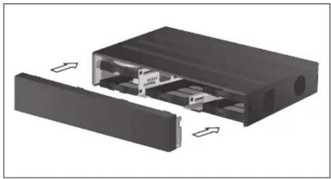
Illustration of a device internal structure with a hand inserting a cable into the housing (no text or symbols visible)- Assemble the front panel back to the unit.
When assembling the front panel to the main unit, make sure the marked part is tightly attached.
- Fasten 2 screws on both ends of the main unit.
natural_image
3D diagram of an internal device housing with two rectangular compartments and directional arrows indicating movement (no text or symbols): Installation
Basic Layout
flowchart
graph TD
    A["Device"] --> B["SpOT Monitor"]
    A --> C["Speaker"]
    A --> D["Microcontroller"]
    A --> E["Camera"]
    A --> F["Mouse"]
    A --> G["IP Router or HUB"]
    A --> H["Sensor"]
    A --> I["Control Devices"]
    A --> J["POS"]
    A --> K["ATM"]
    A --> L["Access Controller"]
    A --> M["Alarm"]
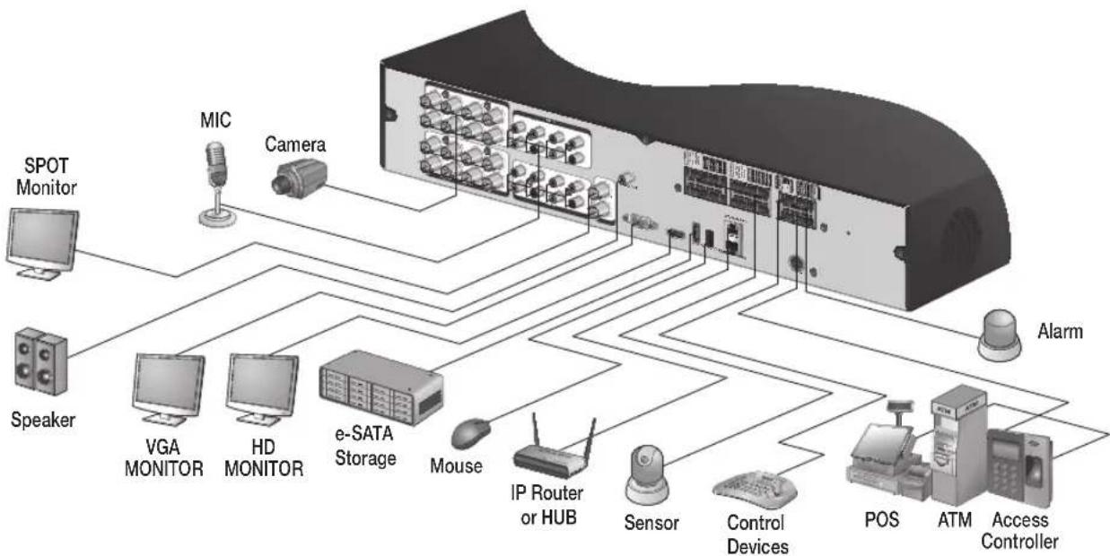
! Since the cable quality may affect directly to the video quality depending on the distance between the camera and DVR, it is recommended to consult an authorized installer when installing the DVR.
Connecting to an external device
Connecting to the monitor
This product supports 1080p 60 Hz HDMI monitors and regular monitors that support DVI and VGA inputs. Use the switch on the product's rear side to set it for HDMI or VGA monitor. Connect an HDMI cable to the port on the product's rear bottom, or connect an HDMI-DVI converter cable to connect a DVI monitor. Or, use VGA cable to connect the product with a VGA monitor.
- Once the product is set for NTSC or PAL output, connect cameras of the corresponding video standard for proper operations.
! Make sure to connect the product to a monitor that supports 1920x1080 at 60Hz. (HDMI, DVI, VGA)
Power Connection
Connect the power cable supplied with the product into the power socket on the main unit's rear side.
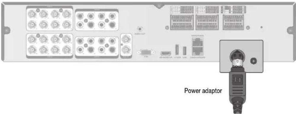
For stable operation of the product, it is recommended to use the adapter provided. (12V, 10A)
! Make connection when the power is not applied yet.
! Arrange up the cables and be careful not to peel off the cable coating.
Do not place the power cord under the carpet or rug. The power cord is usually earth-grounded. However, even if it's not earth-grounded, do never modify it on your own for earth-grounding.
Do not insert multiple devices in a single power socket. Otherwise, it may cause a power overload.
For stable power supply, this product provides two separate adaptors and two corresponding AC cords by factory default. Make sure all cables are connected properly.
: Installation
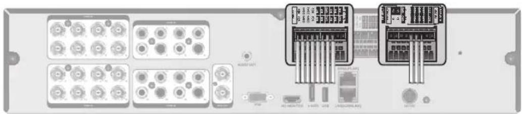
Alarm I/O Connection
natural_image
Back panel of an electronic device showing multiple ports and connectors (no visible text or labels)To connect the alarm input signal
Connect the signal line of an alarm input device such as sensor to the rear [ALARM IN] port.
- Loosen the screws on both the alarm input port and [GND] port of the provided terminal block plug.
- Insert one end of alarm signal cable through the [AO1] or [AO8] terminal hole below the screw hole, and then fasten the screw.
- Insert the ground signal wire into the hole of the [GND] port (shown also below the screw), and tighten the screw.
- To check proper insertion of cable, stop pushing and gently pull the cable and test whether it disconnects. To disconnect a cable, push the bottom side of the terminal and pull out the cable.
To connect the alarm output signal
Connect the signal line of an alarm output device to the rear [RELAY] port.
Loosen the screws on the [NO] and [NC] ports and the [COM] port of the provided terminal block plug.
2. Insert the alarm signal wire into the hole of the [NO] or [NC] input port (shown below the screw), and tighten the screw.
Check the relay output type of Normal Open or Normal Close before selecting a proper type (NO or NC).
NO(Normal Open) : Normally Open but switching to Close if an alarm out occurs.
COM : Insert the grounding wire.
NC(Normal Close) : Normally Close but switching to Open if an alarm out occurs.
- Insert the ground signal wire into the hole of the [COM] port (shown also below the screw), and tighten the screw.
Or, you can connect the signal cable of the alarm output device to the [ALARM OUT] port on the rear side.
- Loosen the screws on the [AO1] and [AO8] ports and the [GND] port of the provided terminal block plug.
- Insert the alarm signal wire into the hole of the [AO1] or [AO8] input port (shown below the screw), and tighten the screw.
Check the relay output type of Normal Open or Normal Close before selecting a proper type (NO or NC).
3 Insert the ground signal wire into the hole of the [GND] port (shown also below the screw), and tighten the screw. - To check proper insertion of cable, stop pushing and gently pull the cable and test whether it disconnects. To disconnect a cable, push the bottom side of the terminal and pull out the cable.
- Install the wire-connected terminal block in the rear port.
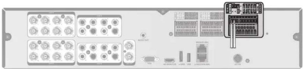
Communication Port
natural_image
Front view of a network equipment rack with ports, connectors, and a highlighted internal panel (no readable text or symbols)RS-485 Connection
Connect a PTZ Camera or Keyboard Controller.
You can connect a text-in device such as POS or ATM.
After connecting the control device, be sure to match the connection settings between DVR and device.
Make communication settings in
- Use a signal cable to connect the [D+] port of the terminal block plug and the [D+] port of the keyboard controller.
- Connect the [D+] port of the terminal block plug and the [D+] port of the keyboard controller.
- Connect the [GND] port of the terminal block plug and the [GND] port of the keyboard controller.
√ For RS-485 communication configuration, refer to the user's manual of the applicable PTZ camera or keyboard controller.
RS-232 Connection
You can connect PTZ cameras, POS or ATM devices.
For connection of the text-in device, refer to the user manual of the text-in device.
Audio Device Connection
You can connect an audio output device such as speaker amplifier.
Connect the audio input device such as microphone to the rear Audio In port, connect the audio output device such as speaker amplifier to the Audio Out port.
: Installation
Storage and Mouse Connection
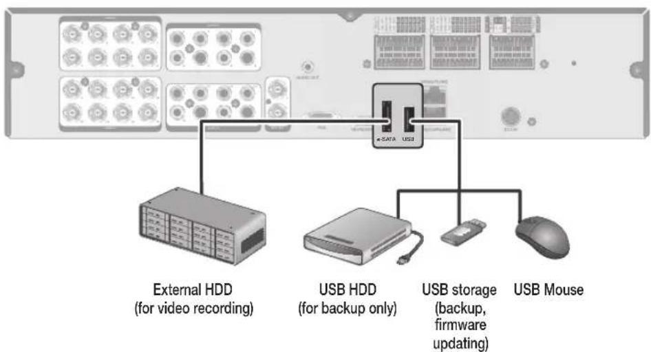
flowchart
graph TD
    A["External HDD (for video recording)"] --> B["USB HDD (for backup only)"]
    B --> C["USB storage (backup, firmware updating)"]
    C --> D["USB Mouse"]
eSATA Storage
If the internal storage space is insufficient, you can extend your storage capacity by adding an eSATA storage device to the rear eSATA port.
Using devices other than recommended eSATA products may cause serious problem.
USB Device
You can connect and use USB storage devices for backup of recorded video, saving snapshots, firmware updating, importing/exporting user configurations. Also, USB mouse can be connected for DVR manipulations.
! If you need to connect a USB HDD with a high power consumption, it is recommended to use a separate power source for that HDD.
Network Connection
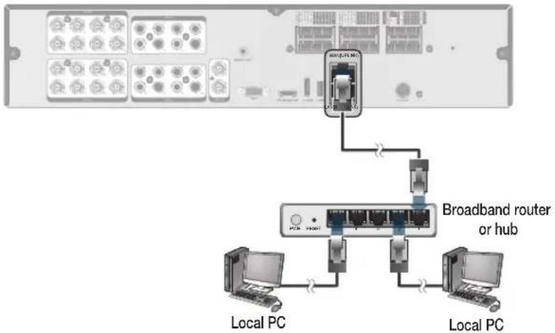
PC connection in the local network
You can connect DVR to a PC in the same network and control or manipulate it on the PC monitor.
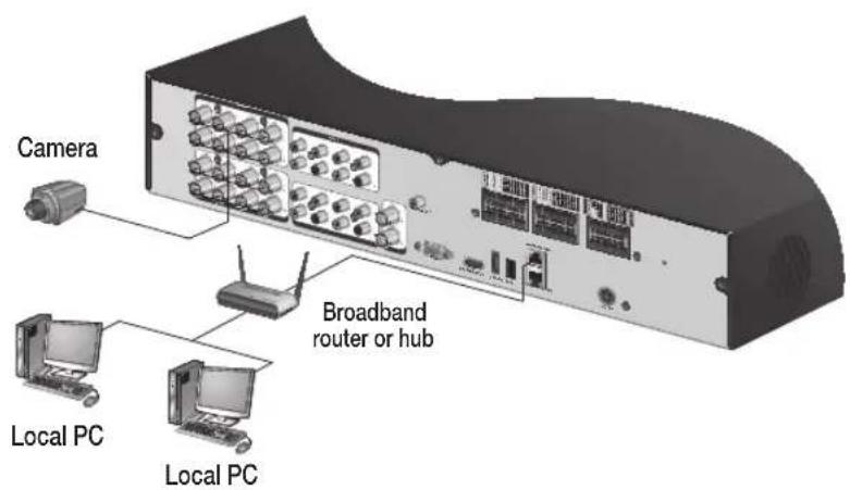
- Connect the [WAN(UPLINK)] port in the rear panel to the router or hub.
The LAN (DOWN LINK) port is provided only for connecting to the dedicated backup network device. (Do not connect devices to this port.)
- Connect the local PC to the router or hub.
flowchart
graph TD
    A["Network Device"] -->|MACS2-PLKING| B["Broadband router or hub"]
    B --> C["Local PC"]
    B --> D["Local PC"]
    style A fill:#f9f,stroke:#333
    style B fill:#ccf,stroke:#333
    style C fill:#cfc,stroke:#333
    style D fill:#fcc,stroke:#333
- Enter the address in the Web browser of your PC in the format of: "http://IP address:Web service port" (Ex : http://192.168.0.23:8080) The web service port is set to 8080 by default. From the Network Setup screen, you can change the port number.
√ If using the dedicated PC S/W, refer to the user manual of the program.
- Provide the ID and password before logging in. Then, you can view the monitoring screen. Access ID (factory default) : ADMIN, P/W : 1234.
! For security purpose, change the password before you use the product for the first time after purchasing it.
: Installation
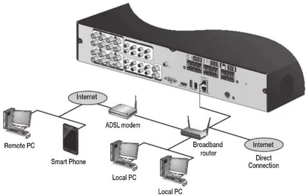
PC connection from a remote network
You can connect DVR to a PC or mobile device in the same remote network and control or manipulate it on the monitor of the PC or mobile device.
flowchart
graph TD
    A["Server"] -->|Internet| B["Smart Phone"]
    A -->|Internet| C["ADSL modem"]
    A -->|Internet| D["Broadband router"]
    A -->|Internet| E["Remote PC"]
    A -->|Direct Connection| F["Local PC"]
    A -->|Direct Connection| G["Local PC"]
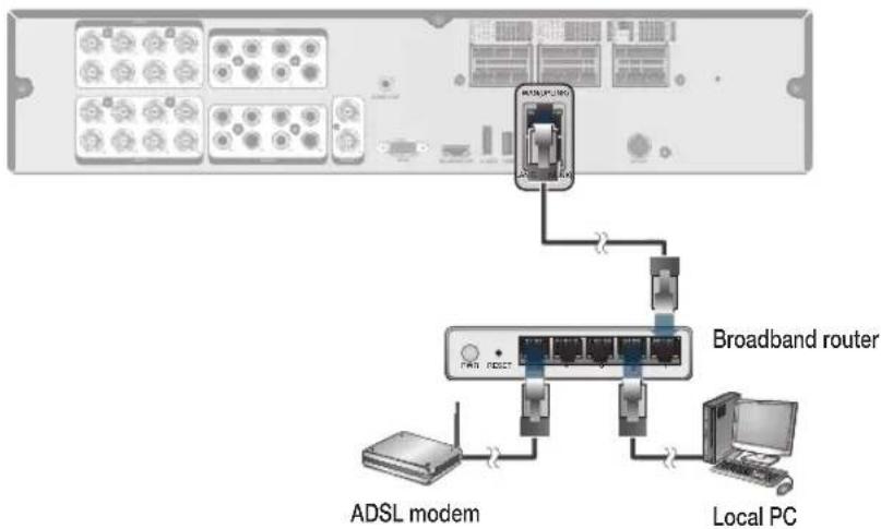
- Connect the [WAN(UPLINK)] port in the rear panel to the router.
The LAN (DOWN LINK) port is reserved and only for servicing and development. (Do not connect devices to this port.)
flowchart
graph TD
    A["ADSL modem"] --> B["Broadband router"]
    C["Local PC"] --> B
    B --> D["Microcontroller with ADSL microcontroller"]
    style A fill:#f9f,stroke:#333
    style C fill:#ccf,stroke:#333
    style B fill:#cff,stroke:#333
- Connect the [WAN(UPLINK)] port of the router directly to the fixed IP LAN cable, or connect it to the ADSL modem.
- If using the router, set the port forwarding and enter the DDNS address in the address bar (web browser) of the remote PC, or of the dedicated software program or mobile phone. For the IP and DDNS address settings, refer to "Network Setup". (page 50)
- If the MAC address of the DVR is 00-11-5F-12-34-56 and the web port number is 8080, enter "http://00115f123456.dvrlink.net:8080" in the address bar of the web browser. If you have renamed DDNS as "mydvr", you can make network connection at http://mydvr.dvrlink.net:8080.
Monitoring

START
- Connect the adaptor to the power input port on the DVR's rear side.
! Make connection when the power is not applied yet. - Turn on the power switch in the rear panel of DVR. With a beep, the logo screen appears several seconds after the front LED turns on.
- When the booting process is completed, the live screen then the login screen appears.
Log In
To manipulate or access the menus of DVR, you should have logged in.
- When the system starts, the login screen appears.
- Select a user and provide the password. The default password of the "ADMIN" account is "1234".
- Click
. If the login information is correct and valid, you will see the live screen.
For security purpose, change the password before you use the product for the first time after purchasing it.
![LOG IN USER ID ADMIN PASSWORD ~ 1 2 3 4 5 6 7 8 9 0 - = ← q w e r t y u i o p { ] \ DEL a s d f g h j k l . " ENTER z x c v b n m < > ? SPACE SHIFT OK CANCEL](/content/2026/05/979638/images/36456adab199fd6e45842b3660cb1fdca6f34c2f97d6c2d1a9c50e12b7d58796.jpg)
Log Out
To prevent unauthorized access, it is recommended to log out when you leave the screen.
√ Hover the cursor near the bottom of the screen to display the menu.
- In the monitoring screen, click
- While logged out, Search / Backup / System Settings / Record Settings / Exit menus are restricted to use.
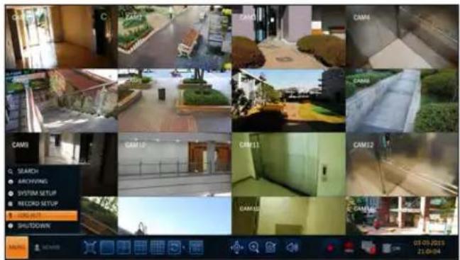

Monitoring
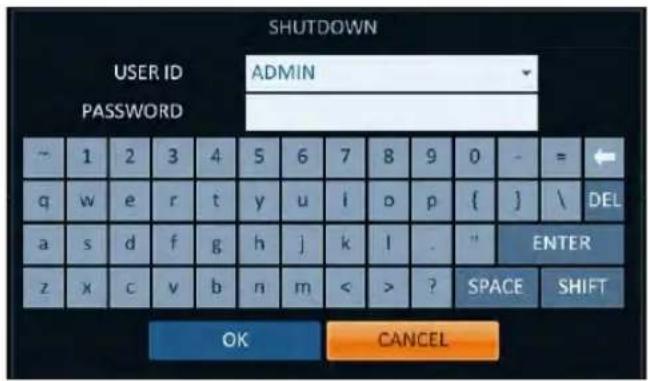
System Shutdown
- In the monitoring screen, click
- Use the virtual keyboard to enter the password.
- Be sure to turn off the power switch in the rear panel.
If you turn off the system in an abnormal manner such as removing the power cord while the system is in operation, the disk will have or increase the bad sectors, causing data loss and shortened life cycle of the disk.
Live Screen At a Glance
The live screen largely consists of three components: video window, status bar and timeline zone.
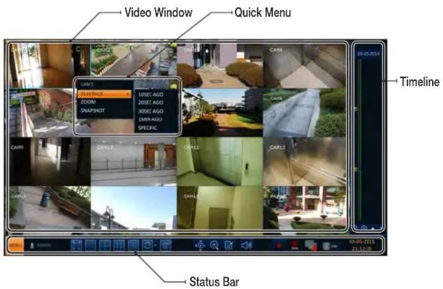
Video Window
Icons used in the video window.
| Item Description | ||
| Camera ID | CAM1 | Show the camera ID. |
| Record Mode Icons | Displayed if an event recording is reserved. | |
| Display the status of the continuous recording. | ||
| Display the recording status when an alarm occurs. | ||
| Display the recording status when a motion event occurs. | ||
| Display the status of the emergency recording. | ||
| Audio I/O Icons | The audio signal of the connected camera is outputting. | |
| Motion Detection Icon | A motion is detected by the connected camera. | |
Status Bar
Press the [▼] button on the remote control, or place the mouse in the lower area of the screen to display the status bar.
| Item Description | ||
| Menu Button |  | Select one of the system setup, search and backup menu items before accessing it. |
| User ID | ADMIN | Show the ID of the user who has currently logged in. |
| Screen Control Buttons |  | Edit the screen layout to show the status bar and timeline at all times or only when the mouse cursor hovers on the status bar/timeline. |
 | Select a split mode. | |
 | Select Auto Sequence Mode.When a user arranges channels on desired tiles of split screen, such setting is listed for later access. Selecting a screen setup directly switches the screen mode as configured. | |
 | Display or hide the OSD menu on the screen. | |
| PTZ |  | Move to the PTZ screen. You can control the PTZ operations of a PTZ-compliant camera on the PTZ screen. |
| Zoom |  | Move to the Digital Zoom. |
| Quick Log |  | Display the log list of the recent recording events. |
| Audio Channel Selection Button | [SDZA] | You can use the camera supporting the audio input to listen to the audio. |
| Panic Record |  | Start the panic recording. |
| Alarm Indicator | [0001] | Turns on if an event occurs. It does not turn on if no reaction to the event is yet defined. Click this to check the information of the event that occurred. |
| Network Connection Status | [0008] | Check if network connection is made via an external PC or mobile device. Click this to view the details of the concurrent users and to check the network connection status. For more information, refer to "Network Setup". (page 50) |
| Disk Space |  | Show the disk space information. If you have set the disk overwrite mode, it will be displayed "OW" (Over Write) from the start point of the overwriting. Click this to view the details of the disk status. For more information, refer to "Record Setup". (page 73) |
| Date & Time | 01-01-201513:38:21 | Display the current time and date. |
Timeline
Press the [▶] button on the remote control or move the cursor to the right of the screen to display the timeline. Double-click the timeline to move to the video screen. Drag and drop it to make backup or event search for the specified area.
| Item Description | ||
| Timeline Date | 01-01-2015 | Display the date of the current timeline.Click this to select a desired date of the timeline. |
| Expand/Collapse the timeline | Expand or collapse the timeline. | |
| Navigation through Timeline | Navigate through the timeline.You can also use the mouse wheel to do the navigation. | |
| Timeline Bar | Display the recording data with time. The color of each bar indicates the following:•Green : Continuous Recording•Red : Alarm Recording•Blue : Motion Recording•Yellow: Panic Recording | |
Quick Menu
Right click on a channel to display a quick menu popup window.
| Item Description | |
| Channel No Display the number of the current channel. | |
| Play Start playing the video of the selected channel from the specified time. | |
| Zoom Operates (digital) zooming on the selected channel. | |
| Snapshot Capture | Capture the current live video and save it in the .jpeg format.√ Then, you can save the captured video in the HDD or export it to an external USB memory device. |
Monitoring
Using the status bar in the live mode
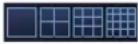
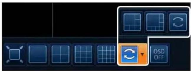
Selecting a split mode
Click a desired split mode from 1, 4, 9 and 16 split screen. Or press the [DISPLAY] button on the remote control until a desired split mode is displayed.

natural_image
Row of six blue rectangular icons with grid and rotation symbols, no text or labels presentAuto sequence
Click the Sequence button in the status bar, or press the [SEQ] button on the remote control to perform the specified sequence mode.
You can configure the sequence settings in
For details, refer to "Sequence". (page 41)
Controlling PTZ
You can control PTZ cameras connected to each channel. Use the mouse to click PTZ button on the status bar, or press the [PTZ] button of the remote control to initiate the predefined sequence.
In PTZ mode, use buttons on the screen to control
PTZ or use [ZOOM], [FOCUS] and [PRESET] buttons of the remote control.


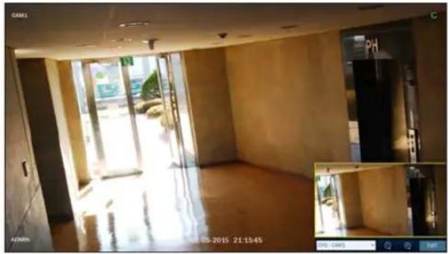
Digital Zooming
You can enlarge the monitoring screen for better view.
Zooming will enlarge the video of the selected channel. If no channel is selected, channel 1 will be zoomed.
- Click Zoom in the status bar or move the cursor to a desired channel and right-click it to display the context menu. Select
. You can also press the [ZOOM] button on the remote control. - Move to the zoom control screen. When the menu bar appears in the right bottom, use the buttons to control the zooming.
CH1-CAM1 : Select a channel to zoom in/out.
: Zoom out the current (enlarged) image step by step.
: Enlarge the current image step by step.
Zoom Box : Use the yellow box to move to or select a desired zooming area.
EXIT : Exit the zooming screen and return to the live screen.
√ Digital zooming magnifies the video image digitally and produces enlarged images that may not be sharp and clear. For sharper and clearer magnification, it is recommended to use cameras supporting optical zooming.
natural_image
Interior view of a modern building with large windows and exposed wooden flooring, showing interior lighting and a close-up photo of a refrigerator (no visible text or symbols)To check the event log
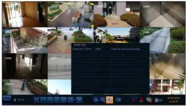
You can check the log of the events that occurred.
- Click Log to display the "EVENT LOG" window. The log list is sorted with the latest one on top.
- Double-click a desired log to display the event video. You will move to the play screen of the selected log.
Monitoring
To select an audio input channel
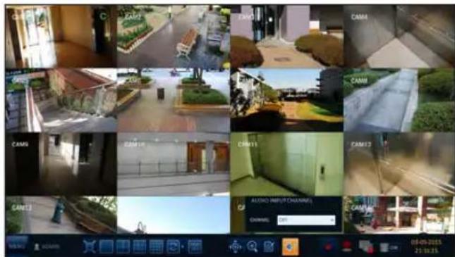
Select a channel from which the audio signal will be received.
CHANNEL : Produces the selected channel's audio, regardless of the split screen mode.
LINK TO FULL SCREEN : When switching the DVR display mode to view one channel (Single Split), it produces the selected channel's audio.
√ A camera supports audio input should be used, and the DVR is connected to a speaker.
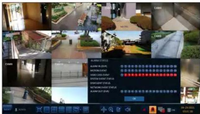
To check the alarm status
You can check alarms and events from each camera and the system.
Click
To check the network status
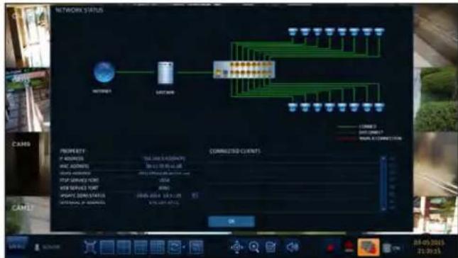
Shows connection status of cameras and network devices. Click to display detailed information on current users and network connections.
Click
√ For more information, refer to "Network Status". (page 52).
flowchart
graph TD
    A["NETNOVER"] --> B["FASTCOR"]
    B --> C["Command Line"]
    C --> D["100%"]
    C --> E["100%"]
    C --> F["100%"]
    C --> G["100%"]
    C --> H["100%"]
    C --> I["100%"]
    C --> J["100%"]
    C --> K["100%"]
    C --> L["100%"]
    C --> M["100%"]
    C --> N["100%"]
    C --> O["100%"]
    C --> P["100%"]
    C --> Q["100%"]
    C --> R["100%"]
    C --> S["100%"]
    C --> T["100%"]
    C --> U["100%"]
    C --> V["100%"]
    C --> W["100%"]
    C --> X["100%"]
    C --> Y["100%"]
    C --> Z["100%"]
    C --> AA["100%"]
    C --> AB["100%"]
    C --> AC["100%"]
    C --> AD["100%"]
    C --> AE["100%"]
    C --> AF["100%"]
    C --> AG["100%"]
    C --> AH["100%"]
    C --> AI["100%"]
    C --> AJ["100%"]
    C --> AK["100%"]
    C --> AL["100%"]
    C --> AM["100%"]
    C --> AN["100%"]
    C --> AO["100%"]
    C --> AP["100%"]
    C --> AQ["100%"]
    C --> AR["100%"]
    C --> AS["100%"]
    C --> AT["100%"]
    C --> AU["100%"]
    C --> AV["100%"]
    C --> AW["100%"]
    C --> AX["100%"]
    C --> AY["100%"]
    C --> AZ["100%"]
    C --> BA["100%"]
    C --> BB["100%"]
    C --> BC["100%"]
    C --> BD["100%"]
    C --> BE["100%"]
    C --> BF["100%"]
    C --> BG["100%"]
    C --> BH["100%"]
    C --> BI["100%"]
    C --> BJ["100%"]
    C --> BK["100%"]
    C --> BL["100%"]
    C --> BM["100%"]
    C --> BN["100%"]
    C --> BO["100%"]
    C --> BP["100%"]
    C --> BQ["100%"]
    C --> BR["100%"]
    C --> BS["100%"]
    C --> BT["100%"]
    C --> BU["100%"]
    C --> BV["100%"]
    C --> BW["100%"]
    C --> BX["100%"]
    C --> BY["100%"]
    C --> BZ["100%"]
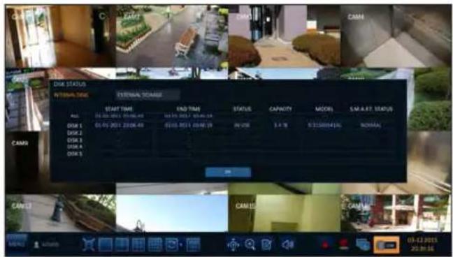
To check the disk status
You can check status and information on storage devices currently connected to the system.
Click
√ For more information, refer to "Disk Information". (page 59).
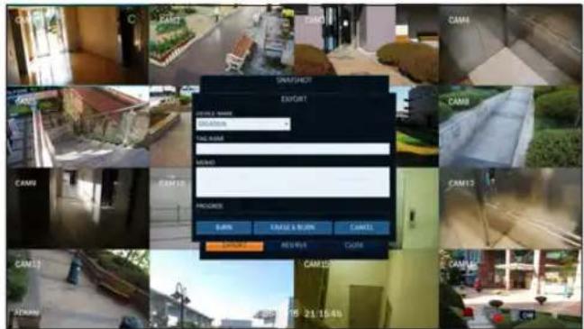
Saving captured snapshots
You can capture the current video screen and save or export to a connected storage device.
- Select a channel first, and right click to open popup menu, and select
menu item, or press the [SNAPSHOT] button of the remote control.
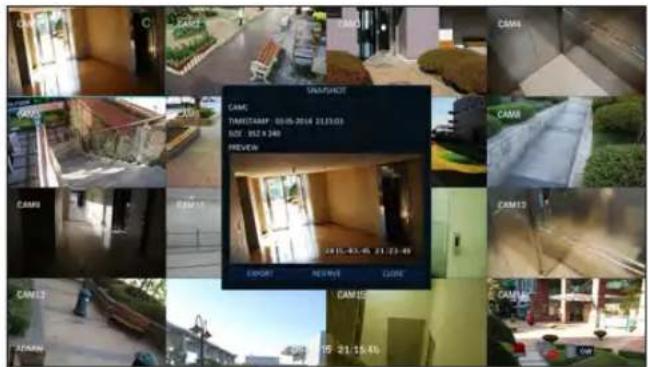
- Connect a storage device, and click
button. To save the captured image onto the built-in HDD, press the button.
√ Saved image can be found in the "Archive > Reserved data management" and can be backed up. (Page 74)
- Enter the
and and press or button.
A progress bar appears and indicates the progress of exporting to storage device.
BURN: Snapshot is stored in the connected USB storage device.
ERASE & BURN : Deletes all files in the connected USB storage and then saves the snapshot.
Note that
System Setting
To move to the System Setup menu
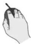
How to use the mouse

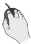
Q SEARCH
ARCHIVING
SYSTEM SETUP
RECORD SETUP
LOG OUT
0 SHUTDOWN
How to use the remote control 1


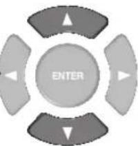
SEARCH
ARCHIVING
SYSTEM SETUP
RECORD SETUP
LOG OUT
0 SHUTDOWN
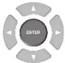
How to use the remote control 2
Camera Setting
You can configure the display settings of: camera title, hidden option, motion and camera type.
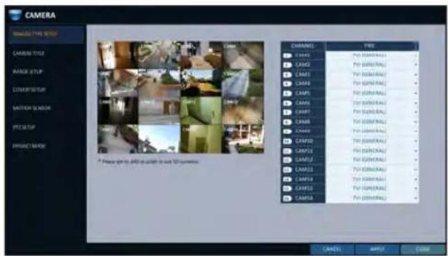
ANALOG TYPE SETUP
You can set the analog type of each camera channel.
- From
- , select . - Use the [▲▼◄►/ENTER] buttons on the remote controller or the mouse to set the type appropriate for the camera connected.
√ Not all types are compatible therefore check before connecting the camera.
- To apply the change, click
in the bottom of the screen. - When done, press the [EXIT] button on the remote control or click
in the lower screen. The confirmation message appears and you will return to the previous menu.
You can change the camera ID that is displayed on the screen.
- From
- , select . - Use the [▲▼◄►/ENTER] buttons on the remote control or use the mouse to select a channel that you want to rename.
Alternatively, simply double-click the camera to rename from the top left corner.
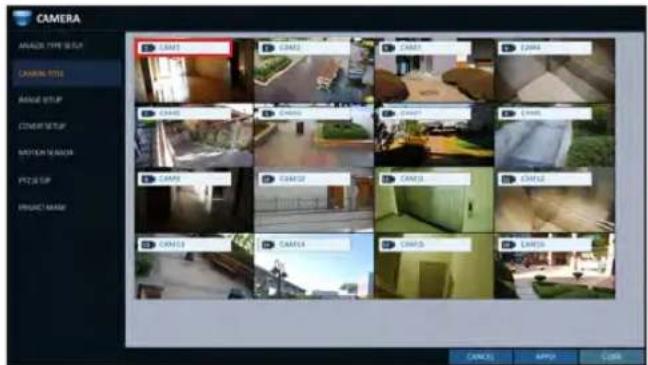
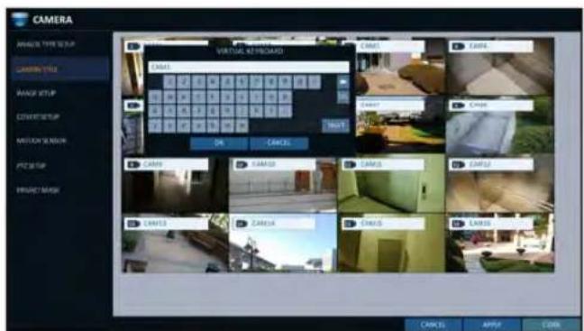
- Once the virtual keyboard appeared, select desired alphanumeric characters to complete your input, and press the
button.
√ Thekey toggles letter case. - To apply the change, click
in the bottom of the screen. - When done, press the [EXIT] button on the remote control or click
in the lower screen. The confirmation message appears and you will return to the previous menu.
√ Camera name allows up to 8 letters, combining numbers and upper/lower case alphabets.
System Setting
Image Setup
You can edit image settings and cropping settings for video from each camera.
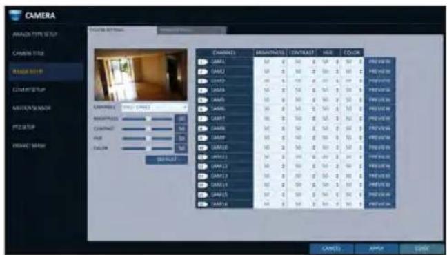
Color setting
You can adjust brightness, contrast, color and quality setting of each channel's camera. (Not available for HD-SDI cameras.)
- From
- , select . - Use [▲▼◄►/ENTER] buttons of the remote control or mouse to edit settings.
- To apply your changes, click
button. - Once completed with setup, press [EXIT] button of the remote control or click
button on the bottom of the screen. A confirmation dialog appears and returns to the previous menu.
√ Press
Crop Setting
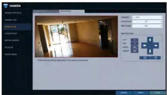
You can cut out unnecessary region of a channel's video.
- , select - .
CHANNEL : Select the channel to set cropping area.
OPERATION : Set whether to use cropping or not.
BOX COLOR : Select the box color to mark the cropping area.
BOX POSITION : Set position and size of the cropping box.
- To apply the change, click
in the bottom of the screen.
- When done, press the [EXIT] button on the remote control or click
in the lower screen. The confirmation message appears and you will return to the previous menu.
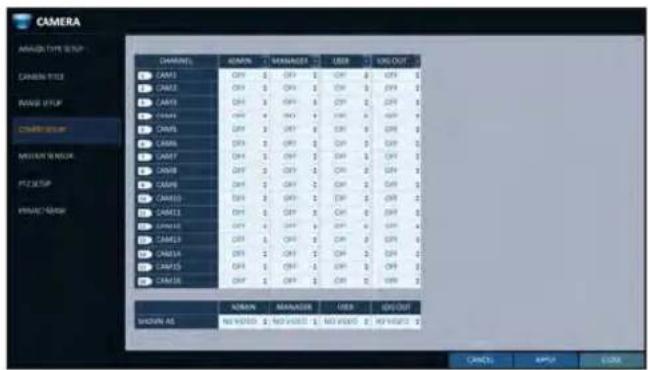
Covert Setup
You can set to hide the camera video so that a specific user or user group can not view. Set a channel(s) that you want to hide from a specific user or user group.
- From
- , select . - Use the [▲▼◄►/ENTER] buttons on the remote control or use the mouse to select a covert channel(s) from a specific user group.
ADMIN, MANAGER, USER : Set them to
LOG OUT : Set it to
. When the user logs out, the current channel will be set to a covert channel.
SHOWN AS : Sets how achannel will be displayed on the monitor.
- No Video : Nothing is displayed on the monitor for the
- COVERT : Hides only the live monitoring.
√ If
- To apply the change, click
in the bottom of the screen. - When done, press the [EXIT] button on the remote control or click
in the lower screen. The confirmation message appears and you will return to the previous menu.
System Setting
Motion Sensor
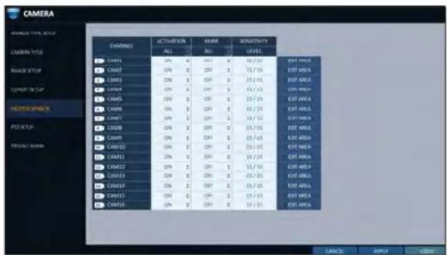
Set the motion sensor of the camera so that it can detect a motion event.
- From
- , select . - Use the [▲▼◄►/ENTER] buttons on the remote control or use the mouse to specify the use of each option item.
ACTIVATION : turn on or off the motion sensor.
MARK : Set toto display the motion detection indicator on each video tile where applicable.
SENSITIVITY : Set the sensitivity level of the motion sensor to either Daytime or Nighttime.
EDIT AREA : Specify the motion detection area.
-
To apply the change, click
in the bottom of the screen. -
When done, press the [EXIT] button on the remote control or click
in the lower screen. The confirmation message appears and you will return to the previous menu.
! The motion detection sensitivity may differ depending on the characteristics of the connected camera or the installation environment.
Motion Area Setup
From the motion setup window, click
- Click
to move to the motion area setup screen. - If using the remote control, press the [ENTER] button to mark the current position.
- Use the arrow buttons to move to a desired block and press [ENTER]. The area setup will begin.
Then, use the arrow buttons to specify the area.
√ Alternatively, you can use the drag-and-drop method to specify or release the area as using mouse. - If you select the specified area again, it will be released.
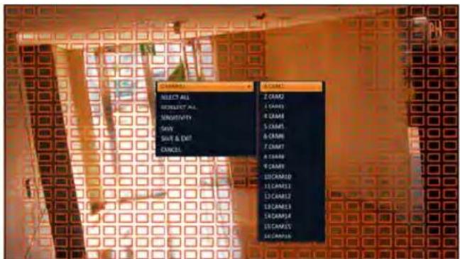
- Press the [EXIT] button on the remote control or right-click any area to display the popup window as in the right picture.
- While the popup window is displayed, select
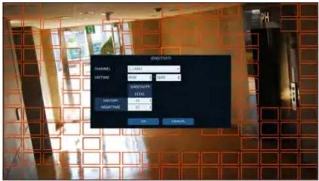
to set the motion detection sensitivity of the channel currently selected.
Channel: Select the channel to set the motion sensitivity.
- SENSITIVITY: 1(Low) \~ 30(High) - The higher the number is, the more higher the sensitivity level becomes.
DAYTIME : specify the time period that will be considered as daytime.
- DAYTIME : specify the
for the daytime. - NIGHTTIME : specify the
for the nighttime.
√ Images recorded in a low contrast scene such as at night cause severe noise, triggering the motion event too often.
√ If unwanted events occur frequently at night, you may want to reduce the motion sensitivity for the night duty.
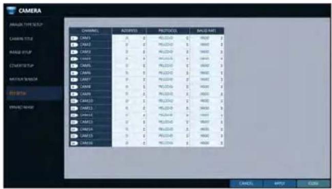
PTZ Setup
You can configure PTZ cameras connected to each channel. Set the camera ID, protocol, baud rate and PTZ control speed for each channel.
- From
- , select . - Use [▲▼◄►/ENTER] buttons of the remote control or mouse to set protocol and bitrate of each channel.
√ Refer to user's manual of the camera or consult camera installation service provider for further details on setting the PTZ camera, such as camera address, protocol and baud rate.
- To apply your changes, click
button. - Once the setup completed, press the [EXIT] button of the remote control or click
button on the bottom to display a confirmation dialog. Click to return to the previous menu.
You can edit privacy mask settings and privacy masking areas for video from each camera.
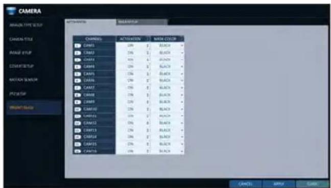
Enabling Privacy Mask
For privacy purposes, you can specify masking area for a selected camera's video.
- From
- , select . -
Use [▲▼◄►/ENTER] buttons of the remote or the mouse to set channels enabled, mask color and its area.
ACTIVATION : Turns on or off the motion detection sensor in the specified privacy area.
MASK COLOR : Select the color of the masked area, which will be displayed on the monitor. -
To apply the change, click
in the bottom of the screen. -
When done, press the [EXIT] button on the remote control or click
in the lower screen to return to the previous menu.
Setting the Privacy Masking Area
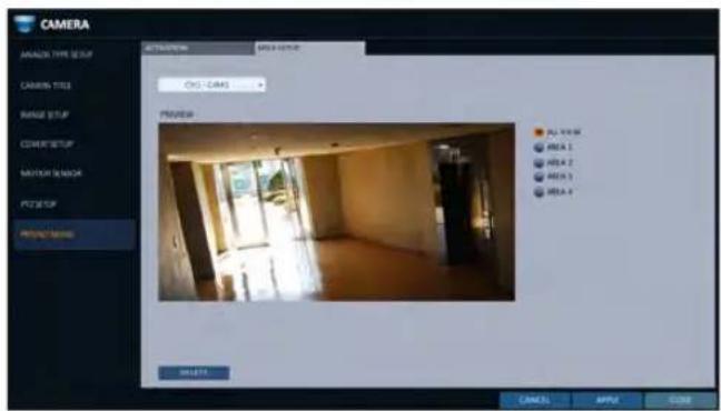
You can specify the privacy masking area.
- Click on the tab on the right side to display the area setup page.
- When using the remote, press the [Select] button to show the selector first.
- Use direction keys to move to the desired channel, and press the [Select] button to begin area setup. Use direction keys to set the masking area. When using the mouse, hold the mouse left button and drag to set or cancel the masking area.
- Selecting masked area again will exclude the corresponding block from the masking area.
Display Setting
You can configure screen display setup for On-screen Display, monitor, dual monitor, sequence, spot out, and POS/ATM.
OSD
You can set Camera Name, Icon, Status Bar, Timeline, Borderline, User Name and Language.
- From
- , select . - Use the [▲▼◄►/ENTER] buttons on the remote control or use the mouse to set each option of the OSD item.
CAMERA TITLE : specify the display of the camera title on the screen.
RECORDING MODE ICON : specify the display of the record mode icon on the screen.
STATUS BAR ON FULL SCREEN MODE : select to show or hide the status bar in full screen mode.
- AUTO HIDE : place the cursor in the lower area of the screen to display the status bar. If moving the cursor up, the status bar will disappear.
- ALWAYS ON : The status bar will be displayed at all times.
- 5 SEC \~1 MIN : If no mouse movement is detected for from 5 seconds to 1 minute, the status bar will disappear.
TIMELINE ON FULL SCREEN MODE : select to show or hide the timeline in full screen mode.
- AUTO HIDE : place the cursor in the right corner to display the timeline. If moving the cursor to the left, the timeline will disappear.
- ALWAYS ON : The timeline will be displayed at all times.
- ALWAYS OFF : The timeline will not be displayed.
ZOOM PIP : You can select the
, <1\~5 sec>, etc. to turn ON/OFF the PIP menu displayed in ZOOM screen.
BORDER LINE : specify the display of the cross-border between channels in a split mode
BORDER COLOR : select a color for the border.
USER NAME : specify the display of the currently logged-in users on the status bar.
LANGUAGE : select a menu display language.
- To apply the change, click
in the bottom of the screen. - When done, press the [EXIT] button on the remote control or click
in the lower screen. The confirmation message appears and you will return to the previous menu.
System Setting
Monitor
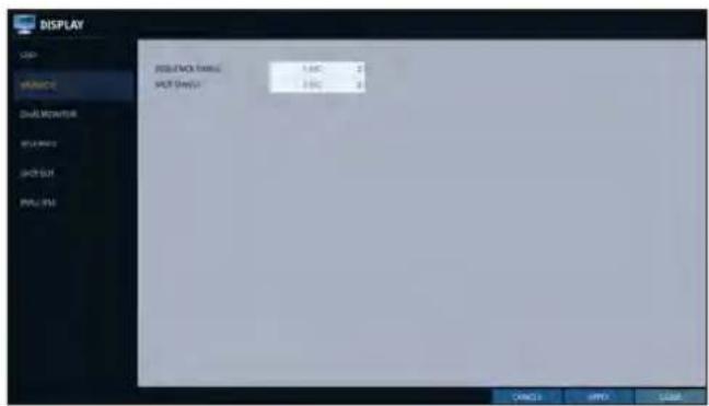
If you change from monitoring mode to sequence, you will have to set the interval of the sequence.
- From
- , select . - Use the [▲▼◄►/ENTER] button of the remote control or mouse to set the dwell for Sequence mode and SPOT Out dwell.
SEQUENCE DWELL: Sets the time interval to the next screen mode for Live monitoring, which defines individual screen mode's dwell time in the Sequence. (Can set to 1 sec \~ 60 sec)
SPOT DWELL : Sets the time interval to the next view type, which defines individual view type's dwell time for SPOT OUT. (Can set to 1 sec \~ 60 sec)
- To apply the change, click
in the bottom of the screen.
4 When done, press the [EXIT] button on the remote control or click
The confirmation message appears and you will return to the previous menu.
DUAL MONITOR
When using the Dual Monitor during surveillance, you can also set the screen mode, type, resolution, and other settings.
-
From
- , select . -
Use the [▲▼◄►/ENTER] buttons on the remote controller or the mouse to set each item of the Dual Monitor.
DISPLAY MODE : When connecting two monitors, you can set the monitor management type.
- DUPLICATE THESE DISPLAYS : The same screen will be displayed on each monitor at the same time.
- MAIN MONITOR+SPOT : You can use one monitor as the main monitor while using the other as a SPOT output monitor.
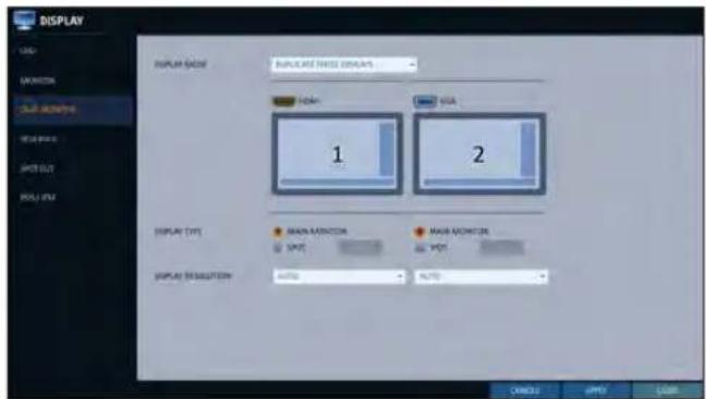
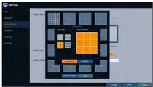
DISPLAY TYPE : Select which monitor to use as the main surveillance and the SPOT output. If you selected the SPOT output monitor, click
to add the view type.
DISPLAY RESOLUTION : Set the resolution for each monitor.
-
To apply the change, click
in the bottom of the screen. -
When done, press the [EXIT] button on the remote control or click
in the lower screen. The confirmation message appears and you will return to the previous menu.
Sequence
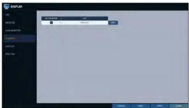
Select a split mode for the sequence, and also select a list of active items when the sequence is performed.
-
From
- , select . -
Use the [▲▼◄►/ENTER] buttons on the remote control or use the mouse to add a sequence or change the settings of the existing sequence.
ACTIVATION : Select a list that you want to activate the sequence for. Only one list will become active.
ADD : add a sequence.
- To apply the change, click
in the bottom of the screen.
- When done, press the [EXIT] button on the remote control or click
in the lower screen. The confirmation message appears and you will return to the previous menu.
System Setting
To add a sequence
- Click
in the bottom of the screen. - When the "ADD" dialog appears, enter a title using the virtual keyboard.
- Enter the name of the sequence and click
. - When the
dialog appears, click . -
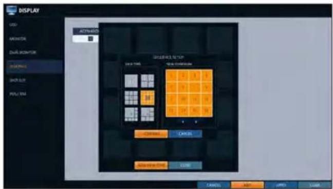
When the "SEQUENCE SETUP" dialog appears, select a split mode that you want to add from
. -
If the selected split mode is displayed on
, select a channel you want to display in each split screen. -
Click
. The set sequence mode is confirmed and will be added to the Add Sequence list in order -
When done, click
in the bottom of the screen. After the sequence type is saved, you will return to the previous screen. -
Place your mouse cursor over a desired tile of added Sequence, right click on it or press the [ENTER] button of the remote control to edit or delete it.
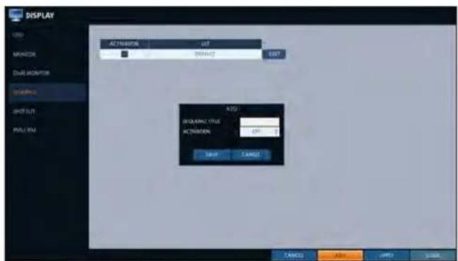
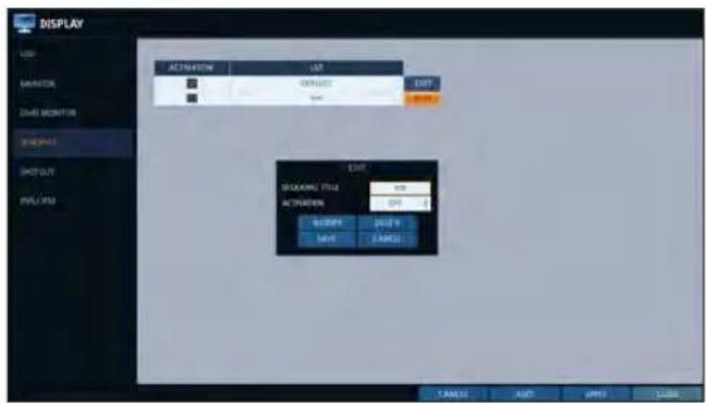
To edit a sequence
- Select a sequence that you want to edit in the list.
- The "EDIT" dialog appears.
- Use the [▲▼◄►/ENTER] buttons on the remote control or use the mouse to edit the selected sequence.
SEQUENCE TITLE : enter a new sequence name.
ACTIVATION : specify the use of the sequence.
MODIFY : change the settings of the sequence mode.
DELETE : delete the selected sequence list.
CANCEL : cancel the changes.
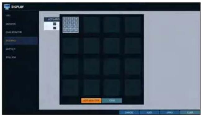
- Pressing the
button will display the Edit Sequence window. - To change the existing settings, select a screen mode that you want to edit and right-click to display the context menu. Then, select
. - When done, click
to close the window. - To apply your changes, click
.
System Setting
SPOT OUT
Apart from the main screen display, you can configure the Spot Out to display a Live channel as needed in various live view types.
You can set the live view type of display output through the [SPOT] terminal and activate / deactivate it.
- From
- , select . -
Use [▲▼◄►/ENTER] button of the remote control or mouse to edit Spot Out properties.
SPOT TITLE : Name the Spot Out setup.
ACTIVATION : Set whether to activate / deactivate the spot out setup.
MODIFY : Edit the view type of the spot output.
SAVE : Save the changes of spot output settings. -
To apply your changes, click
button. -
Once completed with setup, press [EXIT] button of the remote control or click
button on the bottom of the screen. A confirmation dialog appears and returns to the previous menu.
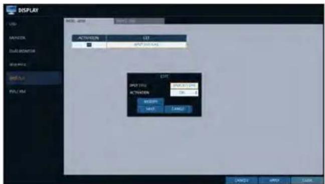
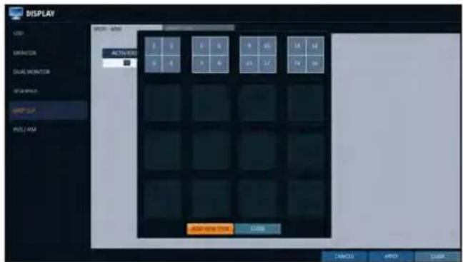
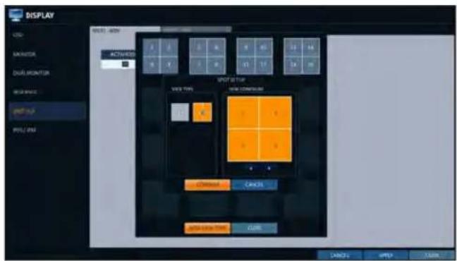
To add a View Type to a Spot Out
- Select an item from the SPOT Output list to be changed.
- The "MODIFY" window appears, click
button. - When the View Type selection window appears, click
button. - Select the desired View Type and configuration, and click
button. - Complete adding and click
to close the edit window
To edit or delete View Type of the SPOT Output
- Select an item from the SPOT Output list to be changed.
- The "MODIFY" window appears, click
button. - When the View Type selection window appears, select the desired View Type to be edited or deleted, and press [ENTER] button of the remote control or right click on it.
MODIFY : Displays "SPOT SETUP" window for editing View Type and other properties.DELETE : Deletes the selected View Type.
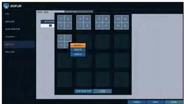
- Complete editing and click
to close the edit window.
System Setting
POS/ATM
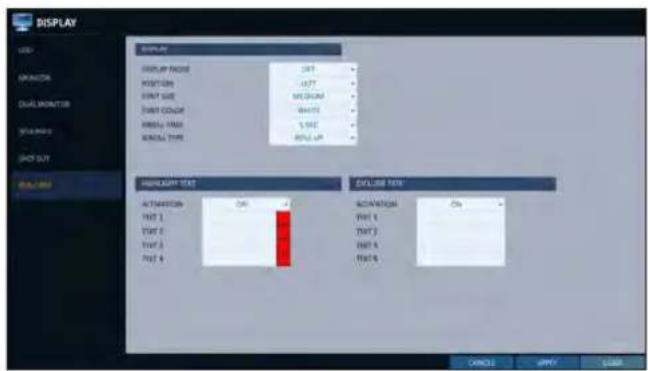
You can change the settings required to interlock the POS/ATM device connected to DVR.
- From
- , select . - Use the [▲▼◄►/ENTER] on your remote control or use the mouse to change the POS/ATM settings.
DISPLAY MODE : You can select the screen where the data entered from POS/ATM are displayed.
- OFF: Nothing is displayed on screen.
- BOTH : Both LIVE and PLAYBACK screens are displayed.
- LIVE : The POS/ATM data are displayed on the LIVE screen.
- PLAYBACK: The POS/ATM data are displayed on the PLAYBACK screen.
POSITION : Select LEFT or RIGHT for the screen position.
FONT SIZE : Select SMALL, MEDIUM or LARGE for your desired font size.
√ The font size is applied to a single split screen only.
FONT COLOR : Select WHITE, GRAY, YELLOW, BLUE, GREEN or RED for your desired font color.
DWELL TIME : You can set how long the data is displayed on screen.
- UNTIL NEXT : Keep the data displayed on screen until the next data are input.
- 1\~60SEC : The data are displayed for the specified time.
SCROLL TYPE : Set the scroll type for screen.
- CLEAR : Display the screen without scrolling.
- ROLL UP : Display the screen with roll-up type scrolling.
HIGHLIGHT TEXT : Select whether to activate the highlighted text or not before entering the text and specifying its color.
EXCLUDE TEXT : Select whether to activate the excluded text or not before entering the text.
√ The POS data are displayed only in 1-, 4-, 6-, and 8- split screen.
- To apply the change, click
in the bottom of the screen. - When done, press the [EXIT] button on the remote control or click
in the lower screen. The confirmation message appears and you will return to the previous menu.
Audio Setup
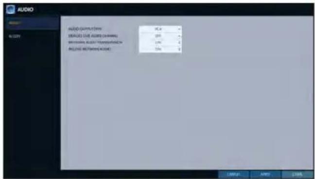
You can configure audio related settings (channel and network transfer) and signal beep for remote control operations.
Audio
Choose whether to receive the live sound source and select an audio channel.
- From
- - Use the [▲▼◄►/ENTER] buttons on the remote control or use the mouse to select an item that you want to edit.
AUDIO OUTPUT TYPE : You can select and use the conventional RCA audio output or the HDMI audio output.
DEFAULT LIVE AUDIO CHANNEL : select an audio channel to monitor on the live screen.
NETWORK AUDIO TRANSMISSION : decide if DVR transfers the audio signal to the remote client. DVR → PC (Remote Client)
RECEIVE NETWORK AUDIO : decide if DVR receives the audio signal from the remote client. PC (Remote Client) → DVR
- To apply the change, click
in the bottom of the screen. - When done, press the [EXIT] button on the remote control or click
in the lower screen. The confirmation message appears and you will return to the previous menu.
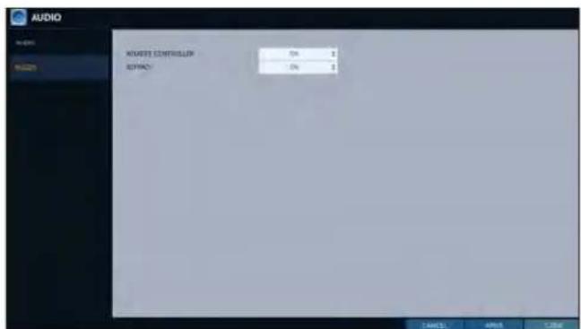
Buzzer
You can set to output the buzzer if you manipulate the remote control.
- From
- - Use the [▲▼◄►/ENTER] buttons on the remote control or use the mouse to select an item that you want to edit.
REMOTE CONTROLLER BEEP : specify the output of a beep when you press a button on the remote control.
KEYPAD : Select whether to output the buzzer when pressing keypad or not.
-
To apply the change, click
in the bottom of the screen. -
When done, press the [EXIT] button on the remote control or click
in the lower screen. The confirmation message appears and you will return to the previous menu.
System Setting
User Setting
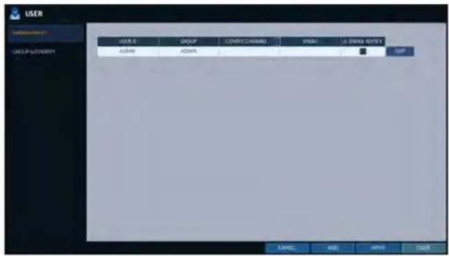
You can configure the settings regarding user management and user and group permissions.
Management
You can add a user account(s) that can be edited at a later time.
- From
- , select . - Use the [▲▼◄►/ENTER] buttons on the remote control or use the mouse to add a user account or select an item that you want to edit.
- To apply the change, click
in the bottom of the screen. - When done, press the [EXIT] button on the remote control or click
in the lower screen. The confirmation message appears and you will return to the previous menu.
To add a user account
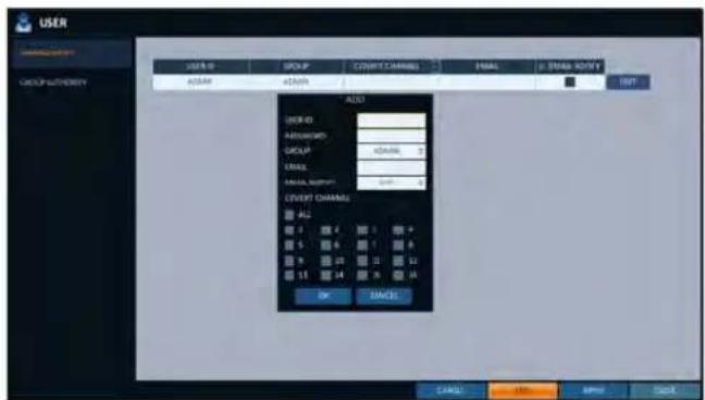
- Click
in the bottom of the screen. - Use the [▲▼▲▶] buttons on the remote control and move to a desired item. Then, press [ENTER] to select the item.
USER ID : enter the user ID using the virtual keyboard.
PASSWORD : With the virtual keyboard, enter the password.
GROUP : From, And , select a group that the user belongs to.
EMAIL : Type in the e-mail address to which you will receive notification of an event if it occurs.
EMAIL NOTIFY : Choose whether you will receive notification of an event if it occurs.
√ To use
COVERT CHANNEL : You can set the channel to hide from a specific user.
√option hides the video of the selected channel from being displayed on the screen.
3 When done, click
The added user account will be listed.
To edit the user account information
- From the list of users, select a user account to edit and click
next to it. - From the Edit window, make necessary changes and click
. - To delete the user account, click
.
√ The
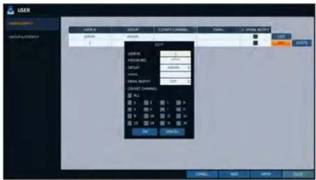
Group Authority
You can grant different user groups different permissions to a specific menu.
- From
- , select . - Use the [▲▼◄►/ENTER] buttons or use the mouse to set the permissions for both
and groups.
SEARCH : Set the permissions for the Search menu.
ARCHIVING : Set the permissions for the Backup menu.
SYSTEM SETUP : Set the permissions for the System Setup menu.RECORD SETUP : Set the Access Permissions for the Record Setup menu.
EVENT ACTION CONTROL : Set the permissions to output the alarm or control the buzzer if an event such as alarm occurs.
LISTEN TO AUDIO : Set the permission to listen to the audio.
REMOTE LOG IN : Set the permission to access remotely.
SHUTDOWN : Set the permission to shut down DVR from the System menu.
√ Theaccount is the master account allowed for all permissions, which is not edited for individual permissions.
- To apply the change, click
in the bottom of the screen. - When done, press the [EXIT] button on the remote control or click
in the lower screen. The confirmation message appears and you will return to the previous menu.
System Setting
Network Setup
You can set IP address, DDNS and E-mail settings, and check network status.
IP Setup
Edits IP address related properties and remote service port of the DVR.
- From
- , select . - Use the [▲▼◄►/ENTER] buttons on the remote control or use the mouse to specify each item of the network settings.
DHCP : If it is checked, set the IP address of the DVR to Dynamic IP.
- If the
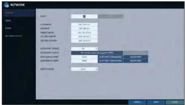
! If you select to obtain an IP address from the
RENEW : The network server restarts and re-allocates dynamic IP address.
IP ADDRESS : Provide the IP address.
GATEWAY : provide the gateway address.
SUBNET MASK : provide the subnet mask address.
1ST DNS SERVER : Enter the address of the primary DNS server.
2ST DNS SERVER : Enter the address of the secondary DNS server.
AUTO PORT UPDATE : Regularly updates the selected WEB and RTSP ports of the router through UPNP function.
AUTO PORT STATUS : You can check AUTO PORT FORWARDING setup is properly configured.
RTSP SERVICE PORT : port number that the remote client receives the DVR video from.
WEB SERVICE PORT : port number used for connecting to the DVR with the web browser.
PORT FORWARDING : If you are using a router, you can set the port forwarding so that external access to the DVR is enabled. If the router does not support the uPnP protocol, you must set the port forwarding manually. For more information, contact your network administrator.
DELETE PORT : release the port forwarding settings for the router.
MAX TX SPEED : Limit the network transfer rate to access a remote client. The video signal may be transferred at a less rate than specified, which depends on the status of your network connection.
-
To apply the change, click
in the bottom of the screen. -
When done, press the [EXIT] button on the remote control or click
in the lower screen. The confirmation message appears and you will return to the previous menu.
DDNS
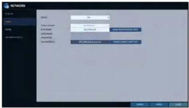
You can configure the DDNS settings so that remote users who are connected to the network can access remotely.
√ DDNS is an IP redirection service in a dynamic IP environment that redirects (maps) the new IP address to a registered domain name each time the IP address is changed.
- From
- , select . - Use the [▲▼◀▶/ENTER] buttons on the remote control or use the mouse to specify the use of DDNS and select a server.
DDNS : Specify the use of DDNS connection.
DDNS SERVER : Select a server to connect to.
DVR NAME : Enter the name of the DVR that you want to use as DDNS.
DDNS REGISTRATION TEST : Check if thecan be set as DDNS. If there is a duplicate name in the server, the registration will fail. If this is the case, rename the and press Test to check if it works properly. USER NAME : Use this field only if you set DDNS server to dyndns.org.
PASSWORD : Use this field only if you set DDNS server to dyndns.org.
DVR ADDRESS : Provide theand press the button. The name will be added automatically.
DDNS CONNECTION TEST : Perform the connection test to check if DDNS is normally registered.
3 To apply the change, click
4. When done, press the [EXIT] button on the remote control or click
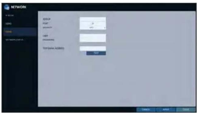
You can register and test an email address so that an email notification is delivered at a specific interval or if an event occurs.
- From
- , select . - Use the [▲▼◄►/ENTER] buttons on the remote control or use the mouse to specify the use of email and select a server.
SERVER : Set up the mail server. Set the mail server that will be used for notification to the DVR. Use the virtual keyboard to enter your mail server.
PORT : Enter the mail server port.
SECURITY : If it is set to, the email will be transferred in secure mode. If it is set to , the email will be transferred to a server that does not support SSL.
USER : Provide the email account (ID) of the sender.
PASSWORD : Provide the password of the sender.
TEST EMAIL ADDRESS : Enter an email address for the test purpose.
TEST : Send a test email and check if the test email is delivered normally.
3 To apply the change, click
- When done, press the [EXIT] button on the remote control or click
in the lower screen. The confirmation message appears and you will return to the previous menu.
System Setting
Network Status
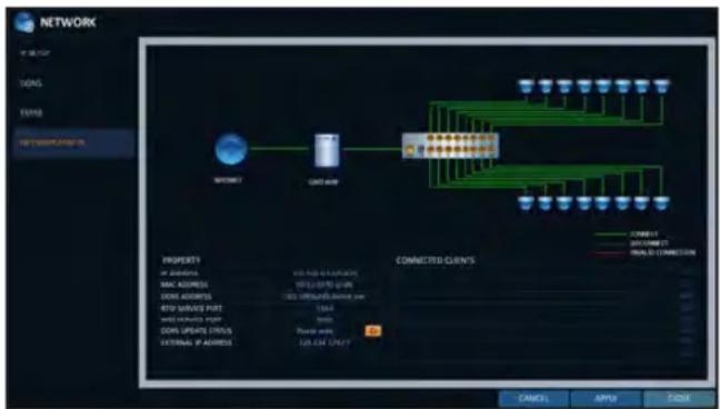
From the network map screen, you can check the internet connection status and camera connection status, and check also the details of the connection status for each camera.
7 From
2. Use the [▲▼◄►/ENTER] buttons on the remote control or use the mouse to select one between
3. When done, press the [EXIT] button on the remote control or click
Network Map
IP ADDRESS : Indicates the internal IP address of the DVR.
MAC ADDRESS : Indicates the internal MAC address of the DVR.
DDNS ADDRESS : Indicates the internal DDNS address of the DVR.
RTSP SERVICE PORT : Indicates the network port of the video service. For remote service, the router must have set up the port forwarding.WEB SERVICE PORT : Indicates the web service network port.
For the remote service to be enabled, the corresponding port of the router should have set up the port forwarding.
flowchart
graph TD
    A["NETWORK"] --> B["MODE1"]
    B --> C["MODE 4"]
    C --> D["CONNECTED CLIENTS"]
    D --> E["OPEN"]
    D --> F["CALL"]
    D --> G["LOAD"]
    style A fill:#f9f,stroke:#333
    style B fill:#ccf,stroke:#333
    style C fill:#cfc,stroke:#333
    style D fill:#fcc,stroke:#333
    style E fill:#ffc,stroke:#333
    style F fill:#fcc,stroke:#333
    style G fill:#ffc,stroke:#333
DDNS UPDATE STATUS : Shows if the DDNS address was registered to the DDNS server normally. Press < to try to register the DDNS address forcibly.
EXTERNAL IP ADDRESS : Indicate the IP address for the Internet, accessible from the DVR. The DVR can be granted access with the web browser at "http://
: . The IP address can vary in a dynamic IP environment. CONNECTED CLIENTS : Shows the list of clients that are currently connected. Press < ■ to terminate the connection of an unwanted client forcibly.
√ Termination is limited to only users in a lower group than the current user.
System Setting
You can configure the settings of date/time, system management, system information, control device and POS/ATM.
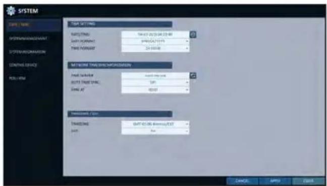
Date/Time
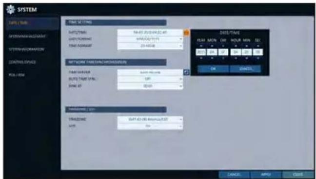
Specify the current date and time.
- From
- , select . - Use the [▲▼◄►/ENTER] buttons on the remote control or use the mouse to change the time or set the options as necessary.
DATE/TIME : Set the current time and date. Click< to adjust the time manually.
DATE FORMAT : specify the date format.
TIME FORMAT : specify the time format.
TIME SERVER : obtain the current time from the time server. Click < 📄 > to get the current time.
AUTO TIME SYNC : automatically synchronize the time with the time server at a specific time.
SYNC AT : Set the time to sync with the time server.
TIMEZONE : specify the GMT standard time for your local area.
DST : You can set up or release the DST (Daylight Saving Time).
√ Both
-
To apply the change, click
in the bottom of the screen. -
When done, press the [EXIT] button on the remote control or click
in the lower screen. The confirmation message appears and you will return to the previous menu.
System Setting
System Management
You can check, update or reset the system information.
- From
- , select . - Use the [▲▼◄►/ENTER] buttons on the remote control or use the mouse to set each option of the system management.
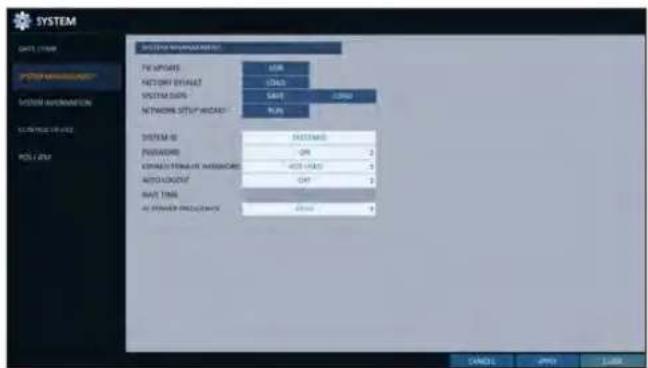
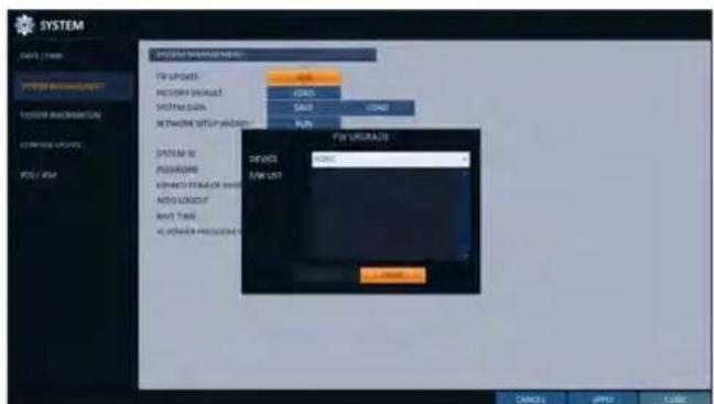
FW UPDATE : you can update the current software with the latest version.
FACTORY DEFAULT : Return the DVR settings to the factory default.
! If you proceed with the firmware upgrade or select to reset to the factory default, all current settings of the DVR will be erased. In such a case, you must configure the network, time and recording settings again.
SYSTEM DATA : Save the system settings or get the system information from other device.
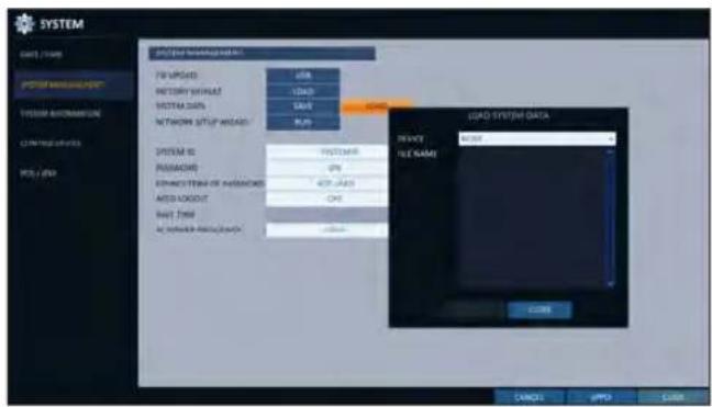
- SAVE : Store the DVR settings to a storage device. Connect the storage device to the USB port of DVR.
- LOAD : Apply the settings of the storage device to the DVR. Connect the storage device to the USB port of DVR.
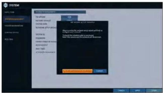
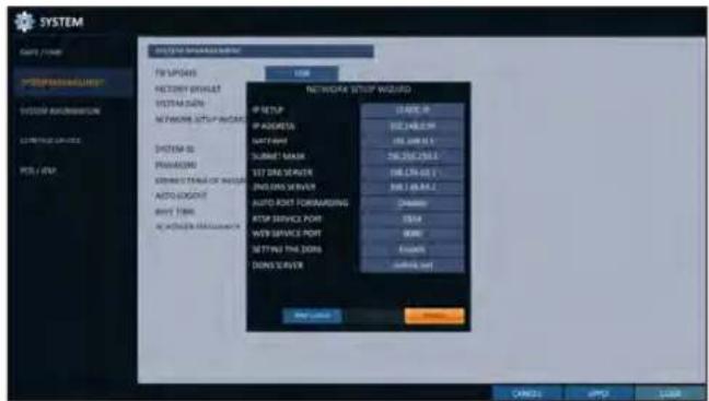
NETWORK SETUP WIZARD : Triggered when the corresponding button is pressed or upon factory initialization. The wizard guides through network configuration such as setting the DHCP or static IP address, WEB and RTSP service ports.
SYSTEM ID : Assign an ID to the DVR to distinguish it out from others when there are multiple DVR used.
√ The default value is "SYSTEM ID".
PASSWORD : Open or close the dialog box for settings of the menus: quit, system settings, record settings, backup, and search.
! If it is set to, note that the ADMIN account is only effective and access to all menus will be restricted.
EXPIRED TERM OF PASSWORD : You will be prompted to change the current password after a certain period of time.
AUTO LOGOUT : If there is no user input for a certain period of time, you can set to log out automatically.
WAIT TIME : Specify the waiting time for Auto Logout.
AC POWER FREQUENCY : Set to the actual AC power's frequency (50Hz / 60Hz) applied to DVR to avoid flickering.
- When done, press the [EXIT] button on the remote control or click
in the lower screen to return to the previous menu.
System Setting
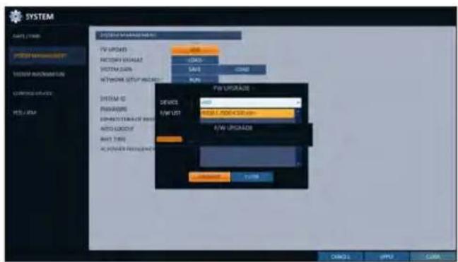
To perform the upgrade
- Connect the USB storage device that contains the updatable files.
- Click
. - Select one(s) from the updatable files listed in
.
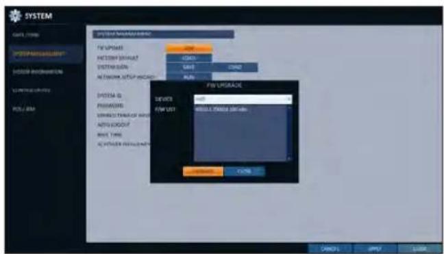
-
Click
. -
When the confirmation message appears, click
.
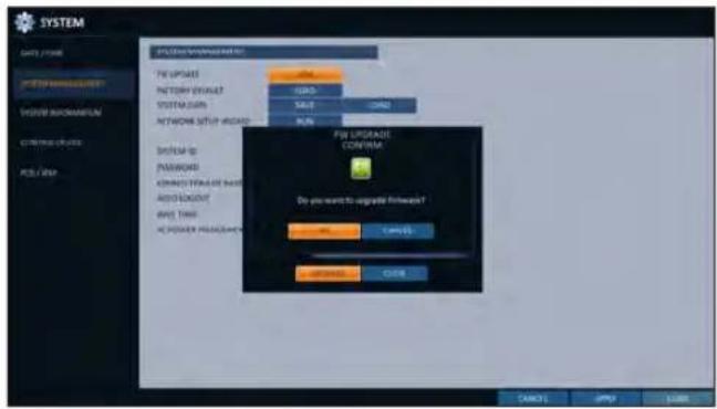
-
The progress bar displays the progress of the firmware upgrade process.
-
When the upgrade is complete, reboot the system.
! If the DVR is forcibly turned off while the firmware upgrade is in progress, this can cause a serious damage to the DVR.
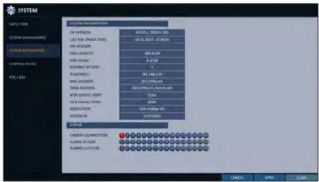
You can check the current system version and system-related settings.
- From
- , select . - Check the status of the current system.
- When done, press the [EXIT] button on the remote control or click
in the lower screen. The confirmation message appears and you will return to the previous menu.
Control Device
Configure the settings of the remote control and keyboard controller.
√ This function is provided for controlling individual DVR separately using a control device or remote control, in case the site has multiple DVRs of the same model.
- From
- , select . - Use the [▲▼◄►/ENTER] buttons on the remote control or use the mouse to set the connection options for the control device.
SYSTEM ID : Set the ID of the DVR so that the keyboard controller can identify.
PROTOCOL : Set up the protocol of the keyboard controller.
BAUD RATE : Specify the RS485 communication speed.
REMOTE CONTROLLER ID : Set the ID of the remote control.
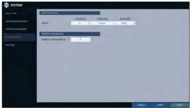
- To apply the change, click
in the bottom of the screen. - When done, press the [EXIT] button on the remote control or click
in the lower screen. The confirmation message appears and you will return to the previous menu.
System Setting
POS/ATM
You can check the configuration of the POS/ATM device connected to DVR.
- From
- , select . - Use the [▲▼◄►/ENTER] on your remote control or use the mouse to check the POS/ATM settings.
ACTION : Specify whether to activate the POS/ATM device or not.
TYPE : Display the type for each channel.
PORT : Display the port for each channel.
- Change the data for each required item, and then press the
button.
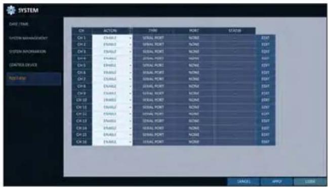
-
To apply the change, click
in the bottom of the screen. -
When done, press the [EXIT] button on the remote control or click
in the lower screen. The confirmation message appears and you will return to the previous menu.
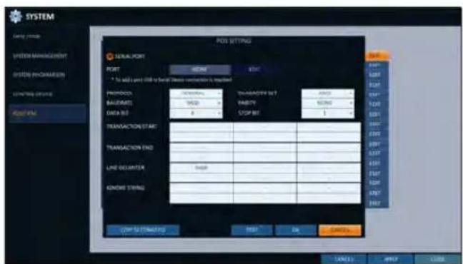
To set the POS
- Press the
button to change in each channel.
PORT : You can change the linked port by pressing the
button on the right.
√ The USB to serial device is required to add a port.
PROTOCOL : GENERAL is designated for PROTOCOL by default.
BAUDRATE : Select the BAUD RATE between 2400\~115200.
DATA BIT: You can select between 5 and 8 for DATA BIT.CHARACTER SET : The ASCII CHARACTER SET is designated by default.
PARITY: You can select NONE, ODD or EVEN for PARITY BIT.
STOP BIT: You can select 1 or 2 for STOP BIT.
TRANSACTION START : Enter the value for TRANSACTION START by using the virtual keyboard.
TRANSACTION END : Enter the value for TRANSACTION END by using the virtual keyboard.
LINE DELIMITER : Enter the value for LINE DELIMITER by using the virtual keyboard.
IGNORE STRING : Enter the string to ignore by using the virtual keyboard.
COPY SETTINGS TO: You can copy the settings to each channel.
TEST: You can test the settings through the POS.
- Complete editing and click
to close the edit window.
Storage
You can configure the settings of and view information of the disk and external storage device.
Disk Information
It will show information about the connected disk.
- From
- , select . - Use the [▲▼◄►/ENTER] buttons on the remote control or use the mouse to select either
or . Please check the status for each connected device.
START / END TIME : show the start time and end time of data stored in each disk.
STATUS : check if the connected disk is being used by the DVR. If you encounter a problem with the disk, the DVR will terminate the connection to the disk and mark it as 'Not In Use'.
CAPACITY : show the capacity of the disk.
MODEL : indicate the disk model.
S.M.A.R.T STATUS : Read the S.M.A.R.T information of the disk and check to display if the current disk is in normal operation.
- NORMAL : The disk is in a normal state.
- CHECK : The disk has an error so that you need to check the disk or the connection cables of the disk.
If you leave the problem unresolved, no recording may be enabled. So it is recommended that you replace the disk immediately.
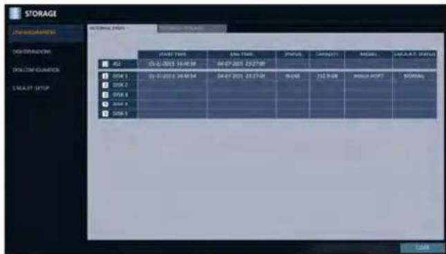
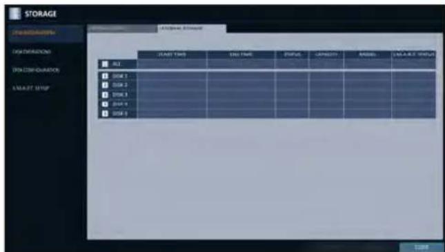
- ERROR : The disk fails or is unable to use due to an error of the disk or the cable. The disk should be replaced immediately. Contact the retailer or the customer service to replace the disk.
- When done, press the [EXIT] button on the remote control or click
in the lower screen to return to the previous menu.
System Setting
Disk Operations
You can set to delete the recording automatically and set the overwrite options, and you can also format the HDD recording data.
- From
- , select . - Use the [▲▼◄►/ENTER] buttons on the remote control or use the mouse to set the operation conditions of the disk.
DISK WRITE MODE
- If it is set to
, the existing data will be overwritten by new recording data if the recording data size exceeds the free space of the HDD. - If the option is set to
and the HDD is full, the DVR will stop recording and output the beep or alarm that is pre-defined at .
RECORDING TIME LIMIT: The recorded data is stored for the designated period by selecting the
, , , etc., and then deleted after the specified period. If it is set to , this function will be disabled. (You can save the recorded data for a maximum of 3 months.)
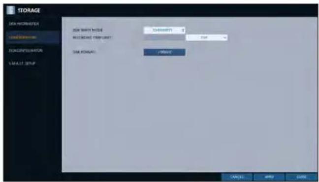
Ex) Record Time Limit : 1 day Even if there is sufficient free space in the HDD, it records / keeps videos of the most recent 1 day only.
DISK FORMAT : format the hard disk.
Note that formatting the HDD will delete all video data and logs.
- To apply the change, click
in the bottom of the screen. - When done, press the [EXIT] button on the remote control or click
in the lower screen. The confirmation message appears and you will return to the previous menu.
Disk Configuration
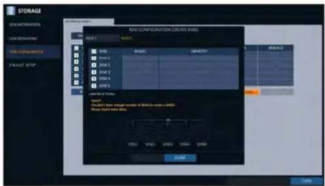
You can generate and configure a RAID array in your internal disks.
√ What is RAID?
RAID is a back-up storage technology which allows you to use multiple independent disks as if they were just a single one.
RAID 1 : The same duplicated data are also recorded in a different drive. That is, the data are equally stored in a pair of drives.
RAID 5 : This mode is the best known RAID array. It distributes and stores data and parity across at least 3 drives.
- From
- , select . - Use the [▲▼◄►/ENTER] on your remote control or use the mouse to change your DISK CONFIGURATION.
MODEL : Display the model of each disk.
CAPACITY : Display the capacity of each disk.
STATUS : If any problem occurs in the disk where a RAID array has been configured, the disk is displayed as Degrade.
REBUILD : Display whether to rebuild each disk or not.
REFRESH : Reload the status of the RAID array.
CREATE RAID : Press the button to create a RAID array.
- To apply the change, click
in the bottom of the screen. - When done, press the [EXIT] button on the remote control or click
in the lower screen. The confirmation message appears and you will return to the previous menu.
To configure a RAID array
- Press the
button on screen.
√ To configure RAID 1, at least 2 disks are required.
√ To configure RAID 5, at least 3 disks are required.
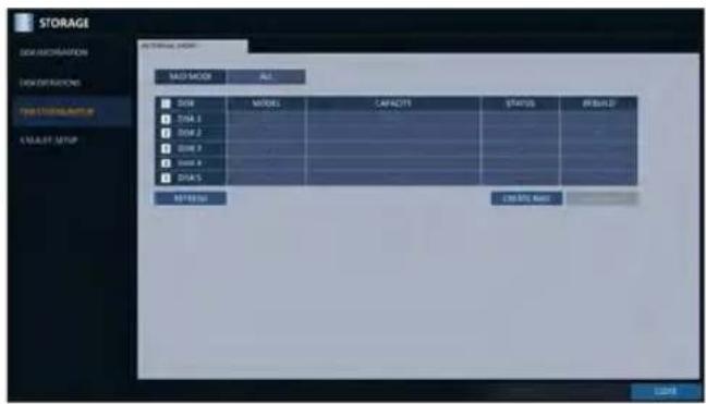
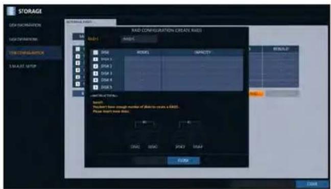
- Check the model and capacity of each disk, configure your desired RAID array, and then press the
button.
! If you modify the RAID configuration, all the data will be formatted.
! To apply the modified RAID configuration, reboot the system.
System Setting
S.M.A.R.T settings
You can check the S.M.A.R.T information of the disk and specify the check frequency.
√ What is S.M.A.R.T information?
S.M.A.R.T (Self-Monitoring, Analysis and Report Technology) is to detect a HDD that is likely to cause a problem in the future with a warning message.
- From
- , select . - Use the [▲▼◄►/ENTER] buttons on the remote control or use the mouse to check the S.M.A.R.T operation and specify the check interval.
S.M.A.R.T STATUS : Read the S.M.A.R.T information of the disk and check to display if the current disk is in normal operation. Click
- NORMAL : The disk is in a normal state.
- CHECK: The disk has an error so that you need to check the disk or the connection cables of the disk.
If you leave the problem unresolved, no recording may be enabled. So it is recommended that you replace the disk immediately.
- ERROR : The disk fails or is unable to use due to an error of the disk or the cable. The disk should be replaced immediately.
Contact the retailer or the customer service to replace the disk.
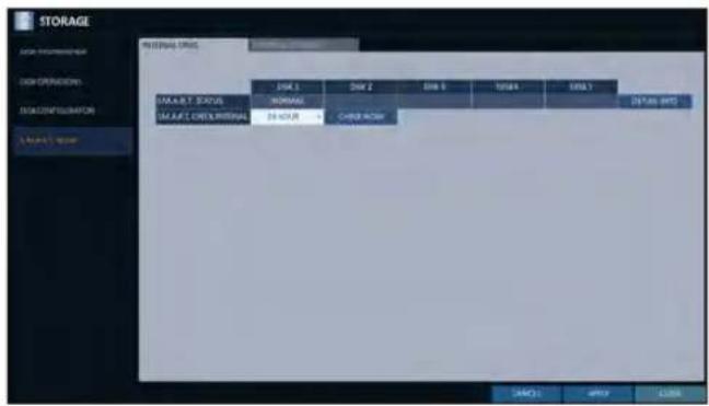
S.M.A.R.T CHECK INTERVAL : Specify the S.M.A.R.T check interval. Click
to start checking.
- To apply the change, click
in the bottom of the screen. - When done, press the [EXIT] button on the remote control or click
in the lower screen. The confirmation message appears and you will return to the previous menu.
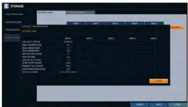
Event Setup
Define various events, and specify the conditions to notify the user in various ways.
Alarm Out
Specify the alarm output conditions with the work schedule.
Alarm Out
- From
- , select . - Use the [▲▼◄►/ENTER] buttons on the remote control or use the mouse to select
and configure the related settings.
NAME: You can rename the alarm.
OPERATION : Set the alarm output mode.
- N/O (Normal Open) : It normally stays Open. However, if an event occurs, it will switch to Close.
- N/C (Normal Close) : It normally stays Close. However, if an event occurs, it will switch to Open.
DURATION : Specify the duration of the alarm output.
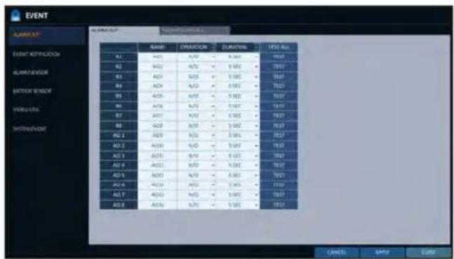
- TRANSPARENT : Keep the alarm out for as much time as the event lasts.
- UNTIL KEY : Keep the alarm out until a mouse or remote control button is pressed.
- 5 \~ 300 SEC : Keep the alarm out for as long as specified.
TEST : Forcibly output the alarm for the test purpose.
- To apply the change, click
in the bottom of the screen. - When done, press the [EXIT] button on the remote control or click
in the lower screen. The confirmation message appears and you will return to the previous menu.
System Setting
ON/OFF Schedule
You can activate or turn off the alarm output as scheduled.
- Use the [▲▼◄►/ENTER] buttons on the remote control or use the mouse to select a
for the schedule. - Drag the mouse to resize the cell or use the on the [▲▼◀▶] buttons to move to the cell, then press [ENTER].
- Select a desired alarm output mode.
ON : The alarm output is always turned on.
OFF : The alarm output is always turned off.
EVENT : Trigger the alarm output in sync with the event.
- Click
to check the checkbox of the date that you want to copy the schedule at. - When done, click
to apply the settings. - To apply the change, click
in the bottom of the screen. - When done, press the [EXIT] button on the remote control or click
in the lower screen. The confirmation message appears and you will return to the previous menu.
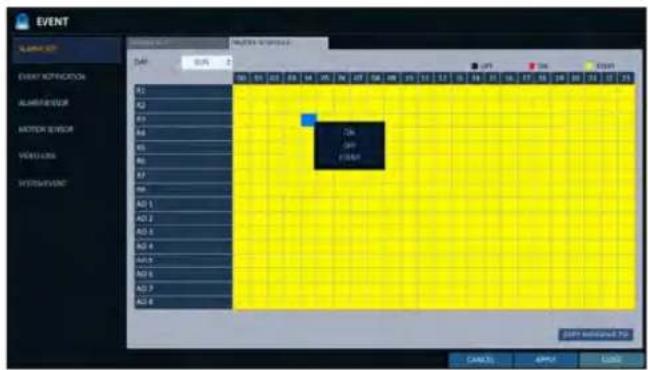
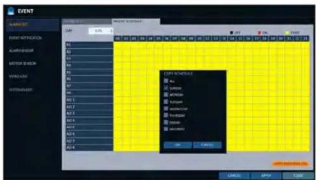
Event Notification
Specify the methods of notification such as buzzer, video popup or email if an event occurs.
7 From
2. Use the [▲▼◀▶] buttons on the remote control or use the mouse to select one from
3 Use the [▲▼◄►/ENTER] buttons on the remote control or use the mouse to set the output method and duration.
4 To apply the change, click
5. When done, press the [EXIT] button on the remote control or click
Buzzer output
You can notify the user of the event using the buzzer.
> DURATION
- TRANSPARENT : Keep the buzzer out for as much time as the event lasts.
- UNTIL KEY : Keep the buzzer out until a mouse or remote control button is pressed.
- 5 \~ 300 SEC : Keep the buzzer out for as long as specified.
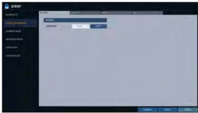
Display
If an event occurs, you can display the video screen or a popup message to notify the user of the event.
VIDEO POPUP : Display the video channel that is synchronized with the event on a single split screen. Set the DURATION of the single split screen.
- TRANSPARENT : Keep the video popup displayed for as much time as the event lasts.
- UNTIL KEY : Keep the video popup displayed until a mouse or remote control button is pressed.
- 5 \~ 300 SEC : Keep the video popup displayed for as long as specified.
√ If multiple events occur at the same time, or if multiple event-related video channels exist, the video popup will be displayed in the maximum split screen mode rather than the single split screen mode.
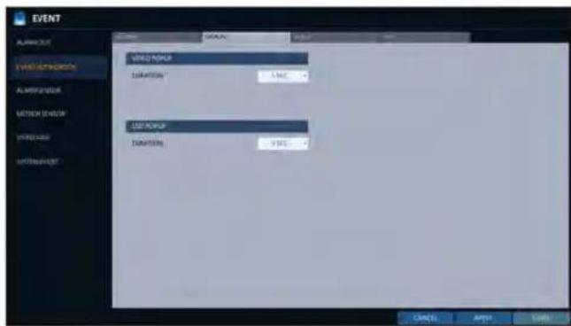
OSD POPUP: This will notify the user of the event with a popup message if an OSD popup event occurs. You can adjust the duration of the popup message.
- UNTIL KEY : Keep the OSD popup displayed until a mouse or remote control button is pressed.
- 5 \~ 300 SEC : Keep the OSD popup displayed for as long as specified.
System Setting
If an event occurs, this will notify registered users of the event by email. If you do not want to receive the email, uncheck the
ADD NEW EMAIL If you want to add a new mail recipient beside the existing ones, click this to add the recipient.
MINIMUM EMAIL FREQUENCY Adjust the minimum frequency of sending the email. For example, even if you have set the minimum frequency to one minute and another event occurs in less than one minute after the last email sending, the email for the new event will be sent one minute after.
√ Some email servers can block the email sending if the email delivery cycle is too short, and classify it as spam.
Contact your email service provider to adjust the minimum delivery cycle so that the server does not classify the email as spam.
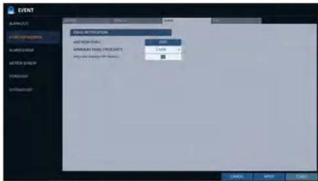
INCLUDE SNAPSHOT IMAGE : Set whether to include snapshot image of the event with the notification.
FTP
Upon events, uploads event notification onto the added FTP server.
FTP SERVER : Enter the FTP server address for event transfer.
DIRECTORY : Select or manually enter the destination folder of the FTP for event transfer.
FILE NAME : Select the uploading event file's format or manually set the file name.
MINIMUM FREQUENCY : Sets the minimum recurrence delay for uploading event notification onto the FTP server. For example, when the minimum recurrence is set to 1 minute, the next FTP event notification will be uploaded after 1 minute from the last event, even if another event is detected within 1 minute from the last one.
INCLUDE WEBRA LINK : Select whether to include WEBRA link address of the event generating DVR, which can be accessed with web browser (Internet Explorer).
√ Check to play back the event footage.
INCLUDE SNAPSHOT IMAGE : Set whether to include snapshot (still image) or not.
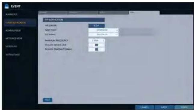
Alarm Sensor
You can configure the settings of the alarm sensor and specify the operation of the sensor if an event occurs.
- From
- , select . - Use the [▲▼◀▶] buttons on the remote control or use the mouse to specify the sensor input method and operation.
NAME: You can specify the name of the alarm sensor.
OPERATION : You can specify the type of the alarm sensor.
NAME : You can specify the name of the alarm sensor. OPERATION : You can specify the type of the alarm sensor.
- N/O (Normal Open) : Normally the sensor is left Open. If the sensor switches to Close, an event will be triggered.
- N/C (Normal Close) : Normally the sensor is left Close. If the sensor switches to Open, an event will be triggered.
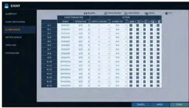
LINKED CAMERA : Set the camera to sync with the alarm sensor if it is triggered.
If you have set the alarm recording and the sensor detects the recording, all synchronized cameras will start alarm recording.
ALARM OUTPUT : Specify the alarm output channel if it is detected by the alarm sensor. The alarm will be output to the specified channel.: Specify the output of the buzzer if an alarm is detected by the alarm sensor.
☐: Select to display the video popup if an alarm is detected by the alarm sensor. If there exist multiple
, the video popup will be displayed in the maximum split mode. ☐: Select to display the OSD popup message if it is detected by the alarm sensor.
: Select to send an email if detected by the alarm sensor.
: Select whether to upload event notification onto the FTP upon detected alarm event.
-
To apply the change, click
in the bottom of the screen. -
When done, press the [EXIT] button on the remote control or click
in the lower screen. The confirmation message appears and you will return to the previous menu.
System Setting
Motion Sensor
You can set an action to execute when a motion is detected. For the settings of the motion sensor, move to
-
From
- , select . -
Use the [▲▼▲▶] buttons on the remote control or use the mouse to specify the ignorance interval and operation.
IGNORING INTERVAL : Specify the minimum interval of the motion event occurrence. For example, even if you have set the minimum frequency to 5 seconds and another motion event occurs in less than 5 seconds after the last motion event occurred, the new event will be ignored. If too many motion events occur, adjust to shorten the interval.
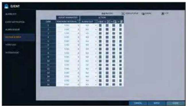
√ Motion recording will be triggered immediately after the motion occurred regardless of the above settings.
ALARM OUTPUT : Specify the alarm output channel if a motion is detected by the motion sensor.
: Specify the output of the buzzer if a motion is detected by the motion sensor.
☐: Select to display the video popup if a motion is detected by the motion sensor.
: Select to send an email if a motion is detected by the motion sensor.
: Select whether to upload event notification onto the FTP upon detected motion event.
3 To apply the change, click
- When done, press the [EXIT] button on the remote control or click
in the lower screen. The confirmation message appears and you will return to the previous menu.
Video Loss
You can specify a reaction to the case where no video is received from the camera.
- From
- , select . - Use the [▲▼◀▶] buttons on the remote control or use the mouse to specify the reaction to a video loss
ALARM OUT : Specify the alarm output channel if a video loss occurs.
: Specify the output of the buzzer if a video loss occurs.
: Select to send an email if a video loss occurs.
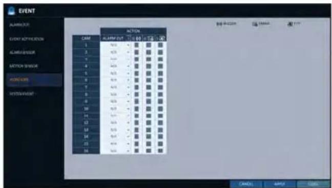
: Select whether to upload event notification onto the FTP upon detected video loss event.
3 To apply the change, click
- When done, press the [EXIT] button on the remote control or click
in the lower screen. The confirmation message appears and you will return to the previous menu.
System Setting
System Event
You can set any action to an event related to the disk, recording, network or system. Like the other events, you may notify the event to the user using the alarm/buzzer output, OSD pop-up or email.
- From
- , select . - Use the [▲▼◀▶] buttons on the remote control or use the mouse to specify the reaction to each event.
- To apply the change, click
in the bottom of the screen. - When done, press the [EXIT] button on the remote control or click
in the lower screen. The confirmation message appears and you will return to the previous menu.
Disk
OVERWRITE START EVENT : if you set the disk write mode to
, this event occurs when the disk is full and the overwriting begins accordingly.
DISK FULL EVENT : if you set the disk write mode to, this event occurs when the disk is full (100%).
DISK SPACE EXHAUSTED EVENT : Event that is triggered if the disk is almost full. Click < → to specify the threshold percentage of usage to trigger the event.
S.M.A.R.T EVENT : Occurs if the disk causes the S.M.A.R.T error.NO DISK EVENT : Occurs if no disk is recognized after the booting due to a disk failure or cable problem.
To detect the disk error, it is recommended not to change the settings of the S.M.A.R.T event, no disk event and buzzer output.
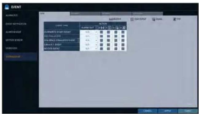
Record
PANIC RECORD START EVENT : Specify the action to perform when the panic recording begins.
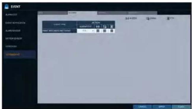
System
BOOTING EVENT: This event occurs when the DVR is booting.
LOGIN FAIL EVENT: This event occurs when the DVR fails to log in.
You can specify the times of clicking <■> to trigger the event.
FAN FAIL EVENT : This event occurs if the CPU cooling fan or unit's cooling fan does not work at all.
√ If the fan fails, no recording will proceed by the DVR. If you encounter a fan failure, contact the retailer or the service center for technical assistance.
TEMPERATURE FAIL EVENT : This event occurs if
the internal temperature of the DVR exceeds the effective range. Then, the DVR will not operate normally. If this is the case, check the followings and take a necessary measure.
- Check if the ventilation of the DVR is clogged with foreign substances. If so, remove them.
- Keep the DVR away from a heat source such as heater. Install it in a flat, lower area with good ventilation.
- If the problem persists, contact the retailer or service center.
To monitor the normal operation of the DVR, it is recommended not to change the buzzer output settings of the fan failure event and the temperature fail event.
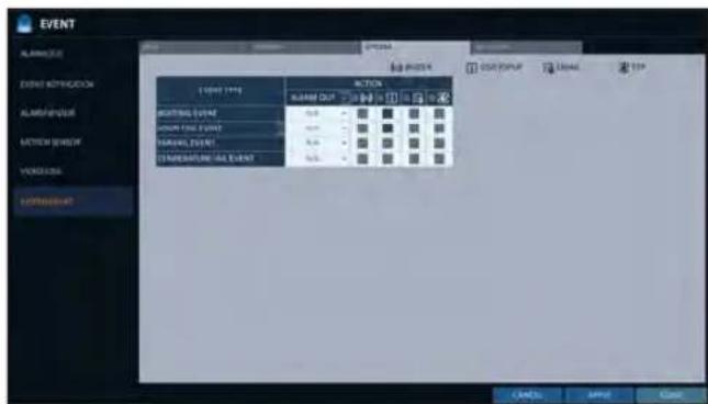
TROUBLE IN INTERNET CONNECTION : Occurs if the Internet connection to the DVR fails. If you do not want to connect the DVR to the network, leave the
item blank.
FAIL IN REMOTE LOGIN : This event occurs if a remote client fails to log in due to an invalid ID or password.
You can specify the times of clicking <■> to trigger the event.
FAIL IN DDNS UPDATE : This event occurs if the DVR tried to update the DDNS address but failed.
√ If the DDNS address fails to be updated, the DVR may not connect to a remote client. If this is the case, enter the IP
address from the client side to allow access from the DVR. This is just a temporary measure.
For the IP address, move to and check
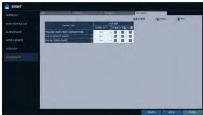
Note that the

Record Setting
You can configure the record settings for the DVR.
Only authorized users can access the Record Setup menu.
To start the Record Setup menu

How to use the mouse


SEARCH

ARCHIVING

SYSTEM SETUP

RECORD SETUP

LOG OUT

SHUTDOWN

How to use the remote control



SEARCH

ARCHIVING

SYSTEM SETUP

RECORD SETUP

LOG OUT

SHUTDOWN
Record Setup
Operation Mode
You can set the recording options for Auto or Manual mode.
7 From
2. Use the [▲▼▶] buttons or use the mouse to set
3. Set the recording options for each selected Record mode.
4 To apply the change, click
5. When done, press the [EXIT] button on the remote control or click
Auto Configuration
If you choose your preferred record mode, the DVR will recommend you the optimized settings for the selected record mode.
CONTINUOUS RECORD : Recording will proceed in the best quality regardless of the event at all times.
As this option will always make recording in the best quality, the recording period is the shortest compared to the other record modes.
MOTION RECORD : Recording will proceed only if a motion is detected.
ALARM RECORD : Recording will proceed only if an alarm event occurs.
MOTION/ALARM RECORD : Recording will proceed only if a motion is detected or an alarm event occurs.
INTENSIVE MOTION RECORD : Normally recording will be performed in a normal quality.
However, the quality will switch to high if a motion is detected.
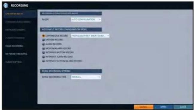
INTENSIVE ALARM RECORD : Normally recording will be performed in normal quality. However, the quality will switch to high if an alarm event occurs.
INTENSIVE MOTION/ALARM RECORD : Normally recording will be performed in normal quality. However, the quality will switch to high if an alarm event occurs or a motion is detected.
√ Motion : Normally, it means the movement of an object. However, it implies a change to the illumination in the context of the DVR. Ex) Vehicle lights (headlights), illumination change, etc.
Manual Configuration
If you set the record mode to
MANUAL CONFIGURATION OPTIONS : You can configure the recording settings by the time, date, and channel.
- SCHEDULE MODE : Set the recording schedule for a day (daily) or for a week (weekly).
- PRE RECORDING TIME : Set the pre-recording time.
- POST RECORDING TIME : Set the post-recording time.
PANIC RECORDING OPTIONS : Set the panic recording duration. If it is set to
, recording will continue until you turn it off manually.
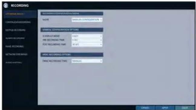
Record Setting
Continuous Recording
You can configure the settings of: continuous recording time, recording size, frame rate per second and quality.
- From the
menu, select .
√ From
- Use the [▲▼◀▶] buttons on the remote control or use the mouse to select either
or .
Size/FPS/Quality Setting
-
Please select the day of the week to perform the continuous recording. From
, you must set the of the to before you can specify the . -
Click a time cell from which you want to edit the SIZE/FPS/Quality and drag it to a desired cell. Or use the [▲▼◀▶] buttons on the remote control to move to the cell and press [ENTER]. Then, use the [▲▼◀▶] buttons to move to a desired cell and press [ENTER] again.
-
When the cell selection is complete, the "SIZE/FPS/QUALITY" table appears.
Specify the
RESOLUTION : set the size of the video recording.
FPS : set the frame rate per second.
QUALITY : set the recording quality.
AUDIO : specify the use of the audio recording.
- When done, click
. You can check the recording size in the size table under the time selection bar.
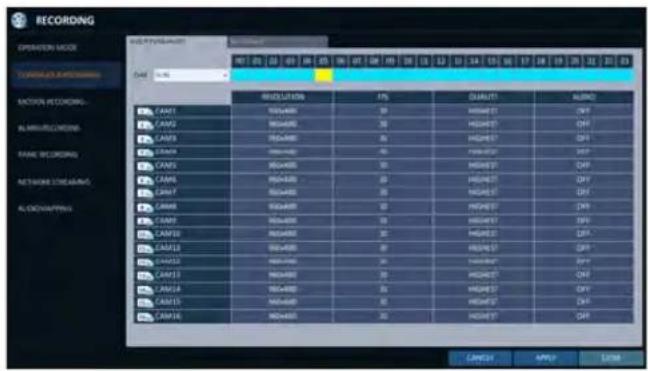
The video resolution and the FPS option may differ depending on the specification of the camera.
Schedule Setting
- Select a start day of the week on the schedule.
- Click a time cell from which you want to make the schedule and drag it to a desired cell. Or use the [▲▼◀▶] buttons on the remote control to move to the cell and press [ENTER]. Then, use the [▲▼◀▶] buttons to move to a desired cell and press [ENTER] again.
-
When the time selection is complete, you will be prompted to specify the use of recording in the Record Setup window.
-
To apply the change, click
in the bottom of the screen. -
When done, press the [EXIT] button on the remote control or click
in the lower screen. The confirmation message appears and you will return to the previous menu.
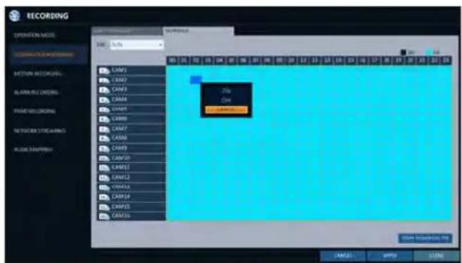
Motion Recording
Specify the recording size of the motion event if it occurs and make schedule for that recording.
- From the
menu, select . - Use the [▲▼◀▶] buttons on the remote control or use the mouse to select either
or . -
Set each item of
, , and use of the -
To apply the change, click
in the bottom of the screen. -
When done, press the [EXIT] button on the remote control or click
in the lower screen. The confirmation message appears and you will return to the previous menu.
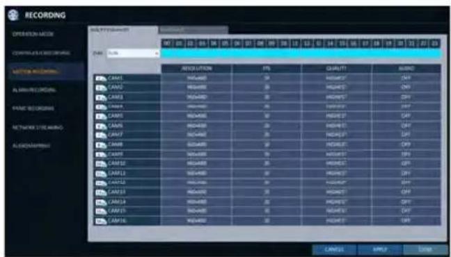
Record Setting
Alarm Recording
Specify the recording size of the alarm event if it occurs and make schedule for that recording.
- From the
menu, select - Use the [▲▼◀▶] buttons on the remote control or use the mouse to select either
or . - Set each item of
, , and use of the
√ For more information, see the "Continuous Recording". (page 74)
-
To apply the change, click
in the bottom of the screen. -
When done, press the [EXIT] button on the remote control or click
in the lower screen. The confirmation message appears and you will return to the previous menu.
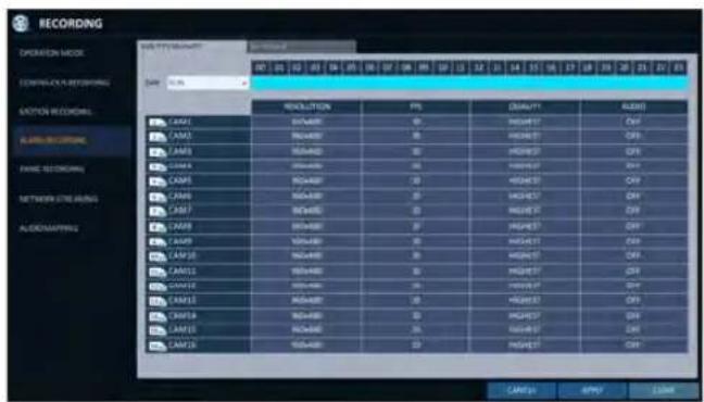
Panic Recording
In panic recording mode, you can specify the recording size and quality of the video.
- From the
menu, select . - Set each item of
, , and use of the
√ For more information, see the "Continuous Recording" (page 74)
-
To apply the change, click
in the bottom of the screen. -
When done, press the [EXIT] button on the remote control or click
in the lower screen. The confirmation message appears and you will return to the previous menu.
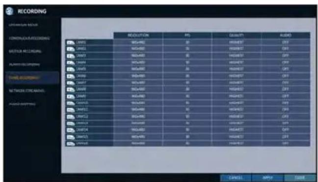
Network Streaming
You can specify the maximum size of network streaming for remote users and set the FPS.
√ Even if you set the resolution and FPS to high for the network streaming, the DVR will reduce the size or FPS according to the network status (speed) before transferring the recording video.
-
From the
menu, select . -
Use the [▲▼◀▶/ENTER] buttons on the remote control or use the mouse to select an item that you want to edit.
-
Set the
and for each channel. -
When done, click
. -
To apply the change, click
in the bottom of the screen. -
When done, press the [EXIT] button on the remote control or click
in the lower screen. The confirmation message appears and you will return to the previous menu.
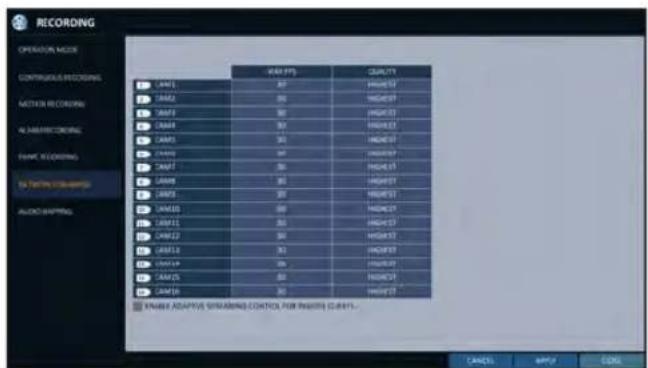
AUDIO MAPPING
-
From the
menu, select -
Set the
-
To apply the change, click
in the bottom of the screen. -
When done, press the [EXIT] button on the remote control or click
in the lower screen. The confirmation message appears and you will return to the previous menu.
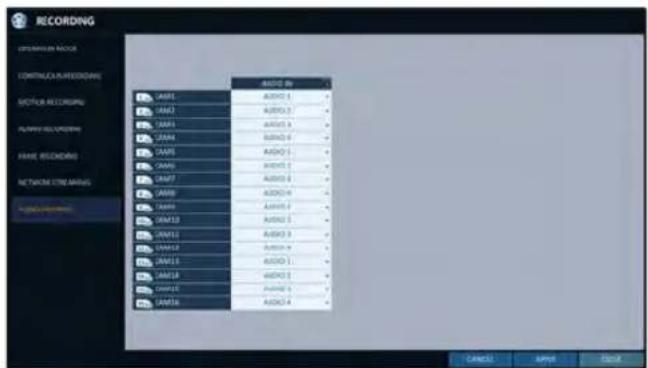

Search
You can search for the recording data in the HDD by the criteria of time, thumbnail, event, text-in, etc.
To move to the Search menu while in monitoring

How to use the mouse

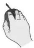
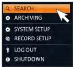
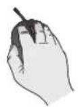

How to use the remote control 1


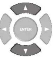
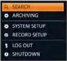
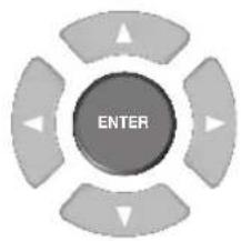

How to use the remote control 2
SEARCH
To move to the Search menu while in playback mode

How to use the mouse

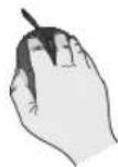
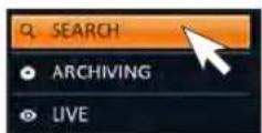
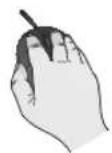

How to use the remote control
SEARCH
Search Settings
Time Search
With the calendar, you can search for the recording data by the recorded date.
- From the
menu, select - Use the [▲▼▲▶] buttons or use the mouse to specify the search date and time from the calendar in the left corner of the screen.
FIRST : The first date of recording is automatically selected.
LAST : The last date of recording is automatically selected.
: Press this to display the time selection menu where you can specify the time and date.
- You can identify the type of the recording data by the color in the bar.
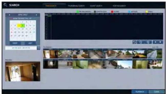
Yellow green (Pre recording) : The pre-recording is performed on the recording data after you set the
from.
Green (Continuous) : The continuous recording is performed on the recording data.
Red (Alarm) : The alarm event recording is performed on the recording data.
Blue (Motion) : The motion event recording is performed on the recording data.
Yellow (Panic) : The panic manual recording is performed on the recording data.
- Click to move to a desired start time in the time bar, or use the buttons at the bottom of the status bar to make search.
: Recall the recording data.
: Expand the timeline of the time bar to a greater unit of time.
: Collapse the timeline of the time bar to a smaller unit of time..
: Use this to move to a previous time that is hidden in the time bar as it is expanded to a greater time unit.
: Use this to move to a next time that is hidden in the time bar as it is expanded to a greater time unit.
- Click a thumbnail channel or use the [▲▼◀▶] buttons on the remote control to move to a desired channel and press [ENTER]. You can check the video in
.
! Click to move to a desired time, or simply double-click a desired time in the time bar to play the video data on that time.
- Press the [ENTER] button again on the remote control with the mouse, or simply double-click on the channel. You will move to the playback screen.
- If you want to stop playing and return to the search screen, press [EXIT] or [SEARCH] on the remote control. You can also click
: Search
Thumbnail Search
To improve your search, you will be provided with a list of thumbnails. Select Day, Hour or Minute to narrow down the search results.
- From the
menu, select . - Use the [▲▼◀▶] buttons or use the mouse to specify the search date and time from the calendar in the left corner of the thumbnail search screen.
FIRST : The first date of recording is automatically selected.
LAST : The last date of recording is automatically selected.
CHANNEL : Select a channel to search for.
DATE/TIME : Specify the search date and time.
√ The menus available differ depending on the selected interval mode.
INTERVAL: Select a time interval of the thumbnail view.
- Double-click a desired play time in the recording data bar, or double-click a desired time image from the thumbnail list.
You will move to the playback screen.
- If you want to stop playing and return to the search screen, press [EXIT] or [SEARCH] on the remote control. You can also click
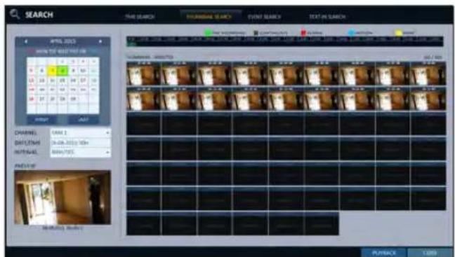
< "Minute" selection screen >
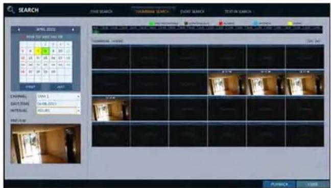
< "Hour" selection screen >
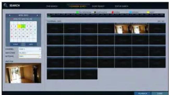
< "Day" selection screen >
Event Search
Search for events that occurred at the specified time and select an event to play from the list.
- From the
menu, select . - Use the [▲▼◀▶] buttons or use the mouse to specify the
and times in the left of the event search list. - Select a channel to search.
- Mark the checkbox of the event to search from the
list. - Press the
button. The search results will be listed as shown.
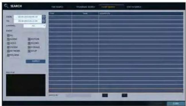
TYPE : displays the event type.
TIME : displays the recording start time.
CONTENTS : shows the details of the event found.
ORDER BY : If you select, the list will be sorted with the earliest one on top.
-
Double-click a desired event or click
in the lower right corner to move to the play screen. -
If you want to stop playing and return to the search screen, press [EXIT] or [SEARCH] on the remote control. You can also click
: Search
Text-in Search
You can search for the text generated at a predefined time and select the text from the list to playback.
- From the
menu, select . - Use the [▲▼◀▶] on your remote control or use the mouse to specify the
and times on the left of the EVENT SEARCH list. - Select the check box(es) for the channel(s) to search.
- Enter the keyword in
- to search for.
MATCH CASE : Perform a case-sensitive search for the keyword entered.
MATCH WHOLE WORD ONLY : Perform an exact word search for the keyword entered.
- Press the
button. The searched keywords are displayed in the list.
TIME : Recording Start Time is displayed.
CHANNEL : Selected channel is displayed.
ITEM : Detail keywords are displayed.
ODER BY : Select theto display the keywords in sequence from the beginning in the list.
-
Double-click a desired event or click
in the lower right corner to move to the play screen. -
If you want to stop playing and return to the search screen, press [EXIT] or [SEARCH] on the remote control. You can also click
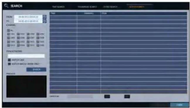
If you want to play
- To play the searched data
- You can search for and play a searched data.
- To play with the live viewer
- Simply double-click a desired time point in the right corner of the play screen.
√ If you move the cursor to the rightmost, the "Timeline" bar will be displayed.
- Select a desired channel in the live screen and right-click to select
Playback screen configuration
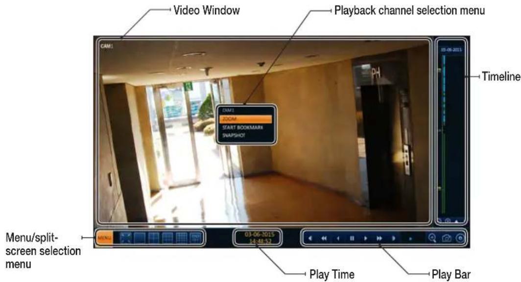
Video Window
Display the current video.
Timeline
Display the type of recording data.
The vertical bar in the timeline indicates the current point of playback. Double-click a desired point in the timeline to start playing the video from that point.
Once you drag to specify an area, you can perform the backup or event search for that area.
Menu / split-screen selection menu
For more information about how to use each button, refer to "Using the status bar in the live mode". (page 28)
Play Bar
You can start playing, stop playing or change the play speed of the current video.
Playback channel selection menu
| Item Description | |
| CAM1 Display the title of the selected channel. | |
| Zoom | Zoom the video of the selected channel. (The zooming function is active only in '1' split screen.) |
| Start bookmarking | The "Set bookmark" popup appears, and you can bookmark a play point for the backup purpose. |
| Snapshot Capture Capture the current live video and save it in the .jpeg format. | |
Using the play bar
| Item Description | ||
| Jump |  | Move forward or backward. |
| Reverse Fast Play |  | The video will be reversely played at the speed of x64 > 32> 16 > 8 > 4 > 2 in this order. |
| Reverse Play |  | Play the video in the reverse direction. |
| Pause |  | Stop playing forward or playback temporarily. |
| Play | [08TY] | Play the video forward. |
| Fast Forward | [2TC3] | The video will be played forward at the speed of x2 < 4 < 8 < 16 < 32 < 64 in this order. |
| Zoom In | [2DX8] | Move to the zoom in/out screen of the selected channel. |
| Snapshot | [2Y7W] | Capture the current live video and save it in the .jpeg format.Then, you can save the captured video in the HDD or export it to an external USB memory device.While you perform the snapshot, the current video will be stopped playing. |
| Start/end bookmark | [TOCA] | Add a bookmark for the current playback screen.Press this to display the "SET BOOKMARK" window. Provide each entry and click Start. The arrow in the bookmark button blinks to indicates that the bookmarking is in process. If you press the Bookmark button again, the bookmarking stops and the current settings will be reserved.Then, the reserved data can be backed up in Archive menu or can be played in the "RESERVED DATA MANAGEMENT" menu. |
Bookmarking
During playback, you can add a bookmark for reserving the video data.
You can view the bookmarked data in the Archive menu, which can be saved to a connected device for the backup purpose.
- Provide a tag in the
item for data reservation. - Provide the details of the reserved data in the
input box.
3 Click.
You will return to the play screen with the backup progress. - To stop the bookmarking, click <BOOKMARK( ).
- To quit the bookmarking, click
. To continue with bookmarking, just click .
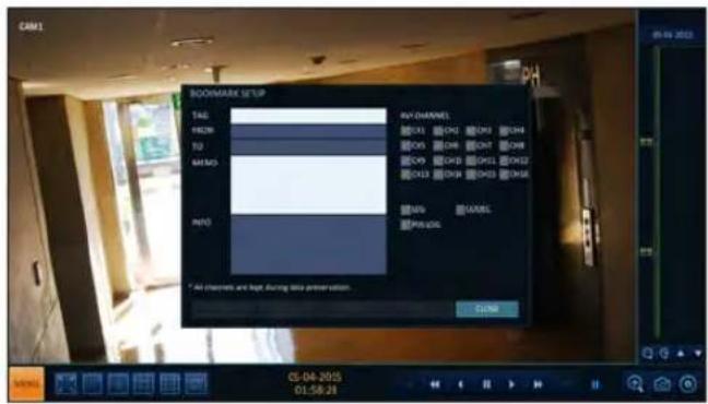
6 Click
You can export the reserved data to a connected storage device using the
√ What is the
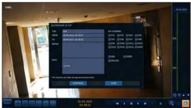
To start the Archive menu
Using the Archive menu during playback
- During the playback, click
- The "ARCHIVING SETUP" window appears where you can reserve the data.
- Click
menu. - Press the [ARCHIVE] button on the remote control.
Using the Archive menu during monitoring
- Click
menu. - Press the [ARCHIVE] button on the remote control.
Archive
You can archive the searched data or reserve it.
- From the
menu, select . - Select a date for the archive from the calendar in the left.
√ The date containing recording data will be marked in a colored box. - FIRST : The first date of recording is automatically selected.
-
LAST : The last date of recording is automatically selected.
-
Check the
and times.
√ Drag the timeline to specify the start and end time.
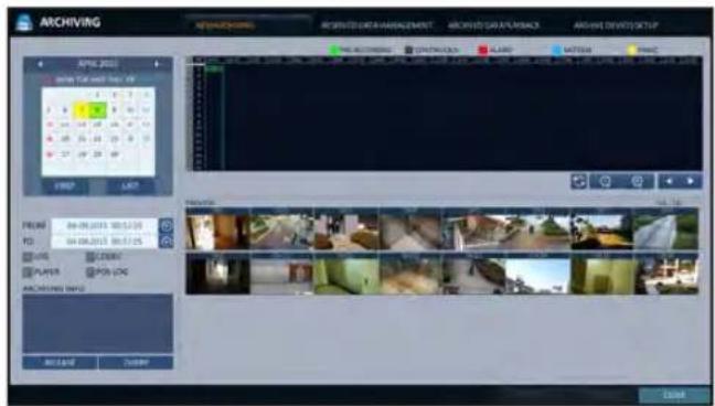
-
Mark the
, , and checkboxes and select to include the archiving. -
Click
. The results will be listed in .
√ The maximum backup capacity for one time is 20GB.
√ If the archiving request exceeds 20GB, the end time will be adjusted to within 20GB.
-
If you want to import to a storage device, connect it to the DVR and click
. -
If you just want to reserve the data, click
. If the dialog appears, enter the name and click . Click to save it to the HDD.
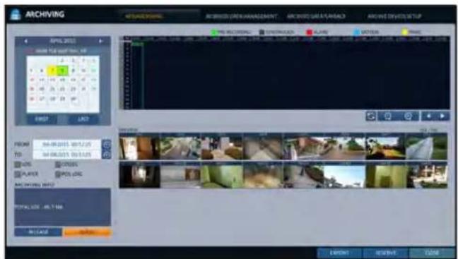
√ Using
- To exit the Archive menu, click
.
Reserved data management
You can search for the reserved data and delete or import it to a storage device.
- From the
menu, select .
The reserved data will be listed.
- Select a data type from
and .
AVI : Searches AVI video files stored in the DVR.
SNAPSHOT CAPTURE : Searches captured snapshots stored in the DVR.
- If you want to play the data, double-click a desired data item or click it and select
.
√ If selecting
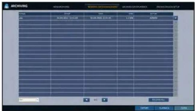
4 If you want to import to a storage device, connect it to the DVR and click
5. If you want to delete the reserved data, click <×> next to the list. Click
6. To exit the Archive menu, click
Playing the archived data
You can search the storage device for the archived data and check the details of or play it.
- Connect the storage device containing the archived data.
-
When the storage device is recognized, click
. -
To view the details, click <next to the list.
√ Click
- Select an item to play from the list and click
. - To exit the Archive menu, click
.
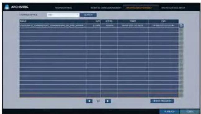
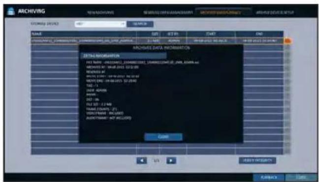
Archiving
Archive Devices Setup
Provide the FTP server information for archiving data in the HDD before testing the transfer.
- From the
menu, select . - Move to the FTP information box.
- Fill in each item using a virtual keyboard.
HOST NAME : enter the address at which you can access the server.
PORT : enter the port number to which you can access the server.
USER NAME : enter the user ID with which you can access the server.
PASSWORD : enter the connection password.
DIRECTORY : specify the archiving path.
- When all information is filled, click
to check the connection status. - To apply the change, click
in the bottom of the screen. - When done, press the [EXIT] button on the remote control or click
in the lower screen. The confirmation message appears and you will return to the previous menu.
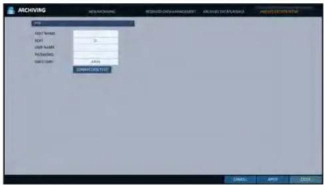
What is the Web Viewer?
Web RA is a user-friendly software application that enables you to control the video data in connection with a remote DVR.
System Requirements
The following is the minimum hardware and operating system requirements to run Web RA.
| Operating System | Windows XP ProfessionalWindows Vista Home Baisc / PremiumWindow 7 |
| Web browsers: | Internet Explorer 7.0 or later/Mozilla Firefox 3.6/Google Chrome 4.1/Opera 10Some web browsers other than Internet Explorer may not fully function. |
| CPU Intel Pentium 4 / 2.0GHz or higher | |
| Memory 512 MB | |
| Display 16-bit 1024 x 768 High Color | |
| Hard Disk Drive | 50 MB (space required for installing the web viewer)* Additional HDD space is required for saving your recording data.The file size of your recording may differ depending on the specified quality. |
Connection
Open a browser and enter the IP address of DVR, or type the URL in the address bar.
To connect to the DVR from inside
- Check the "Network Status" and verify the
and of the DVR. (page 52) - Enter the IP address and web service port in the address bar of the browser. Ex) http://192.168.1.200:8080
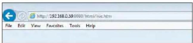
To connect to the DVR from outside
• Using the IP address
- Check the "Network Status" and verify the
and of the DVR. (page 52) - If using a fixed (external) IP, enter the external IP that is specified in the DVR in the address bar of the web browser. Ex) If the internal IP address is set to "http://222.112.4.48:8080" (192.xxx.xxx.xxx), no access from outside is allowed.
- Check the "Network Status" and verify the
and of the DVR. (page 52) - Enter the DDNS address and web service port in the address bar of the browser. Ex) http://00115f123456.DVRLINK.NET:8080
• Using the URL
√ In a router network, you have to set the "Port Forwarding" and "DMZ Setting" to allow access from outside.
√ For the necessary settings of the router, refer to the user manual of the router or contact the manufacturer of the router.
Web Viewer
- Provide the user ID and password.
√ The default User name: ADMIN; the default Password is 1234.
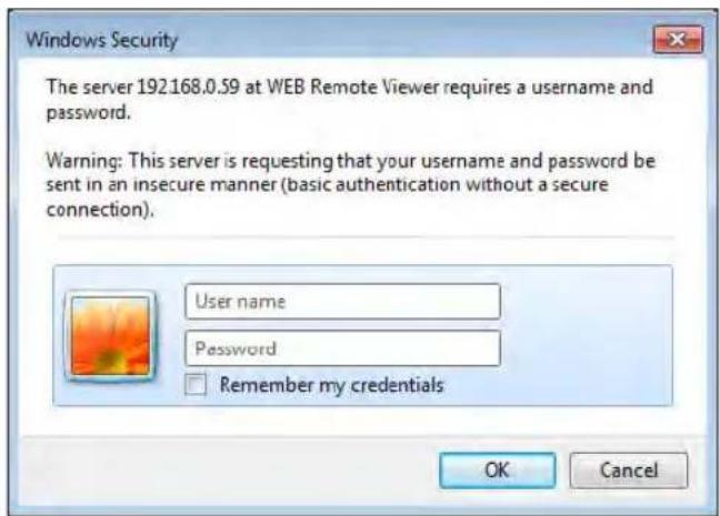
- Click the lower warning bar to install the ActiveX.

√ If you fail to download the ActiveX control, move to Tools
→ Internet Options → Security → Custom Level → Download unsigned ActiveX control, and change its setting from "Disable (recommended)" to "Enable", and then click OK.
-
Click
. -
When the installation is complete, you will see the live screen.
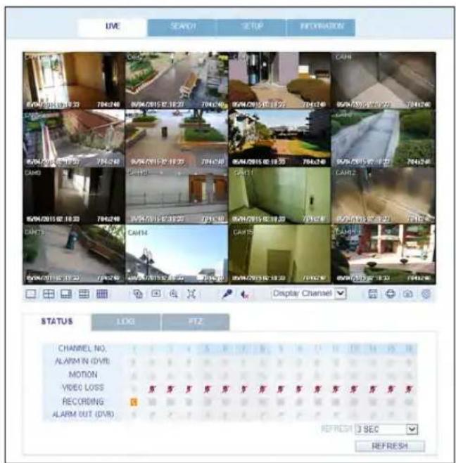
Live
Live Screen At a Glance
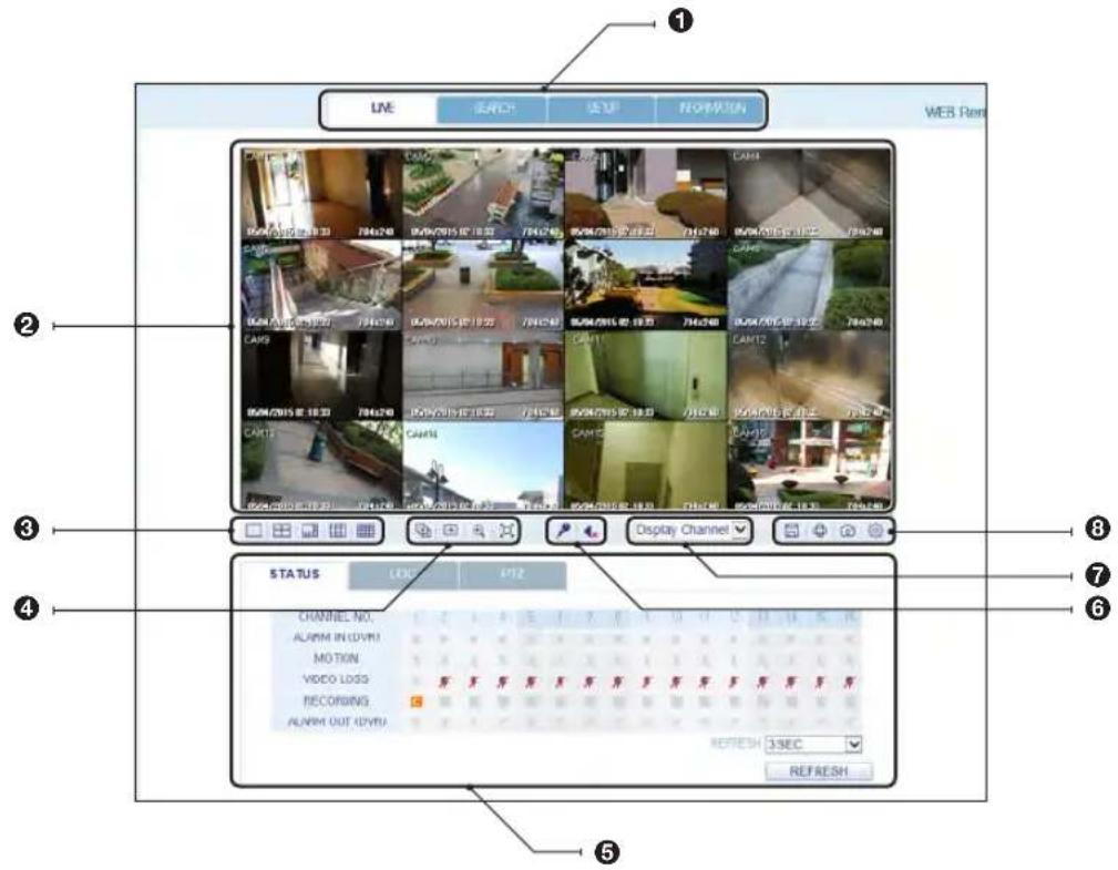
| No. Item Description | |
| 1 | View selection tab You can switch to the live, playback and setup screen and check the provided information. |
| 2 | Live Display the live screen of the currently connected DVR. |
| 3 | Split Mode Select and switch to a desired split-screen mode. |
| 4 | Sequence, Zoom Set the sequence mode, switch to the next camera, zoom the screen or select the full screen mode. |
| 5 | Status Show the connection status of each channel. |
| Log Show the log. | |
| Refresh Time Set the interval at which the DVR Status is refreshed. | |
| Reload Load the DVR Status immediately. | |
Web Viewer
| No. Item Description | |
| 6 | Voice transmission You can turn on or off the output of the voice signal. |
| 7 | Channel Select a channel listed in the screen. |
| Save Save the live video on the screen. | |
| 8 | Print Print out the current screen. |
| Capture Capture the selected image. | |
| ActiveX Settings Configure the ActiveX settings or specify the saving path of the captured image. | |
Switching the split mode
Click the Switch button to switch the mode as follows:
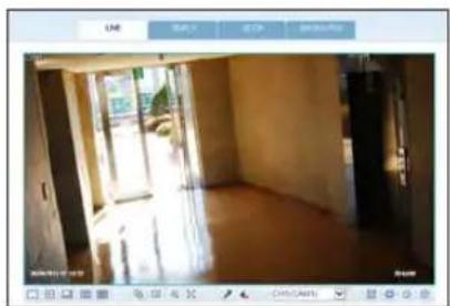
natural_image
Interior view of a dimly lit room with large windows and exposed flooring (no visible text or symbols)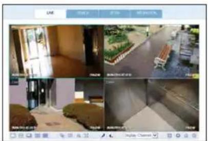
natural_image
Four-panel screenshot of a smart home security camera interface showing outdoor scenes with furniture and lighting (no visible text or symbols)<4-split Mode><1-split Mode>
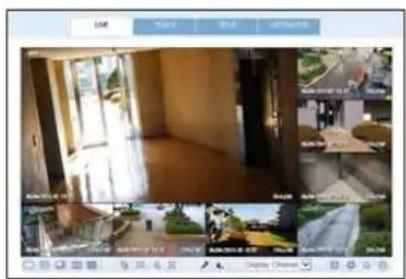
natural_image
Interior view of a modern building with large windows and surrounding greenery (no visible text or symbols)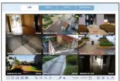
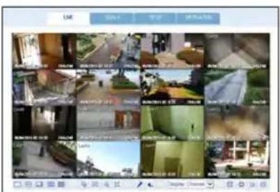
<9-split Mode> <16-split Mode> <8-split Mode>
To save the video
- Click < > to start saving.
- The video from the selected channel will be saved to the PC in the AVI format. (Default path: C:\SaveFolder) Click <图标> again to stop saving. Click
to display the context menu where you can change the saving path.
- Click <
- The current screen will be printed with the printer connected to the PC.
Screen capture
- Click <
- The current screen of the selected channel will be saved to the path specified in the PC. (Default path: C:\SaveFolder) Click
to display the context menu where you can change the saving path.
ActiveX Settings
- Click <
- When the setup screen appears, you can change the settings of the render type, audio, capture and saving path as well as the video streaming.
Render : DirectDraw is recommended in order to enable the hardware acceleration.
- If you want to change the saving path, click <-> (Save Folder) and specify a new path. The Windows Vista user cannot change the saving path.
- Change the streaming settings according to the PC specification and network environment. Auto mode is recommended.
Sync : If this option is set, the audio signal will be synchronized with the video signal. However, you may encounter a delay due to buffering for the synchronization.
Live CH: Set the audio signal to use in live monitoring mode.
I Frame Only : Only the I frames (key frames) will be transferred.
Type
- Auto : The DVR will optimize the quality and FPS to the network status and specification of the connected PC before transferring the data.
- Main: The video will be transferred in high definition (HD).
-
Second : The video will be transferred in a medium definition (SD).
-
When done, click
to save your settings.
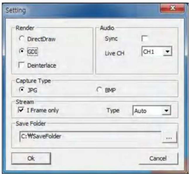
Web Viewer
Status tab
Click
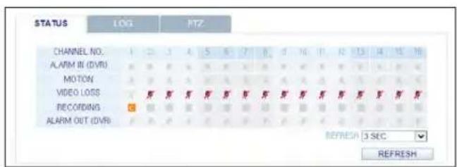
Log tab
Click
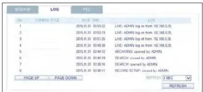
PTZ tab
Click
PRESET : Move the camera in a predefined direction.
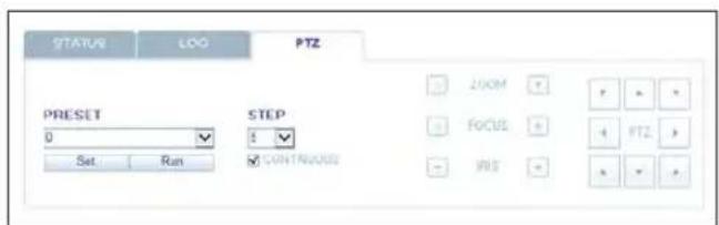
Search
Click
Search Viewer at a Glance
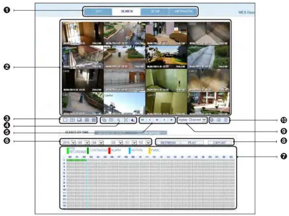
No. Item Description
| 1 | View selection tab You can switch to the live, playback and setup screen and check the provided information. | |
| 2 | Playback Screen Play the recording data. | |
| 3 | Split Mode Select and switch to a desired split-screen mode. | |
| 4 | Sequence, zoom, voice transfer | Set the sequence mode, switch to the next camera, zoom the screen or select the full screen mode.You can turn on/off the voice signal. |
| 5 | Play button bar You can control the playback screen. | |
| 6 | Time Selection Specify the start time of playback. | |
| 7 | Time Line Indicates the status of the recorded data. | |
Web Viewer
| No. Item Description | |
| 8 | REFRESH Reload the time line. |
| PLAY Play the video that satisfies your search criteria. | |
| EXPORT Archive the video that satisfies your search criteria. | |
| 9 | Channel Selection Select a channel listed in the screen. |
| 10 | Screen Print out the current screen. |
| Image Capture Capture the selected image. | |
| ActiveX Settings Configure the ActiveX settings or specify the saving path of the captured image. | |
Search by time
Use the timeline to search for the data recorded in the DVR.
7 Select a date that you want to search.
2. Click
3. Check the existence of recording data in the bottom time line and specify the time range for your search. You can specify the start time by moving the time bar.
4. Click
REFRESH : If your changes are not applied to the current screen, reload the changes.
PLAY : Play the searched video.
Backup : Archive the recorded video.
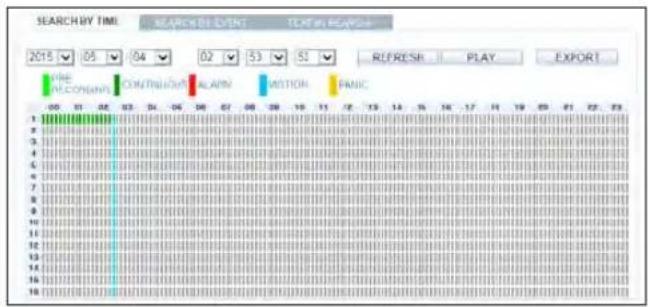
Search by event
You can sort the recording data items by event to facilitate your search.
- Mark the checkbox of the event that you want to search for.
- Specify the start and end dates and times for your log search.
- Set the display order of the items found.
LATEST : The most recent event will be listed on top.
OLDEST : The earliest event will be listed on top.
4 Click
You can check the log for your search at the bottom of the screen.
5. Select a log to play the recording data.
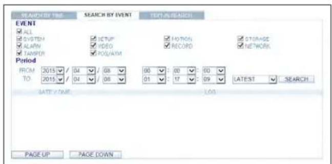
Text-in Search
You can search for the recorded data in DVR by text.
- Enter your desired text to search for in ITEM KEYWORD, and then click the check boxes such as MATCH CASE, MATCH WHOLE WORD ONLY, etc.
- Select the check box(es) of channel(s) to search for.
- Select your desired Start/End date and time to perform the log search.
- Specify the displaying order for the searched items.
√ Refer to the "Search by event" for displaying order of searched items (page 96)
-
Press the
button. You can check the log resulted from the search near the bottom. -
When selecting the log, you can watch the recorded video for corresponding event.
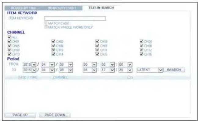
Web Viewer
Setup
Click
When done, click
√ If the DVR is in process of system or record setting, the remote control will be disabled.
! If you change the settings remotely at will, the major 'Record Settings' of the DVR may be changed, which is not recommended at all.
Setup Viewer at a Glance
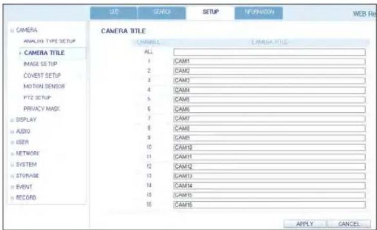
Camera
To name the camera title
You can name the camera title that is displayed on each channel screen. Select a channel to name and provide a new title. Then, click
√ You can enter up to 9 alphanumeric characters for the camera title.
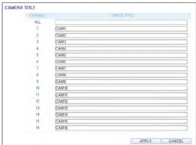
Image Setting
You can set the image of each channel.
When done, click
√ The default color value is <50>. (Brightness, Contrast, Hue, Color)
√ If you change the default settings, the video from the DVR or the video color may not be displayed properly.
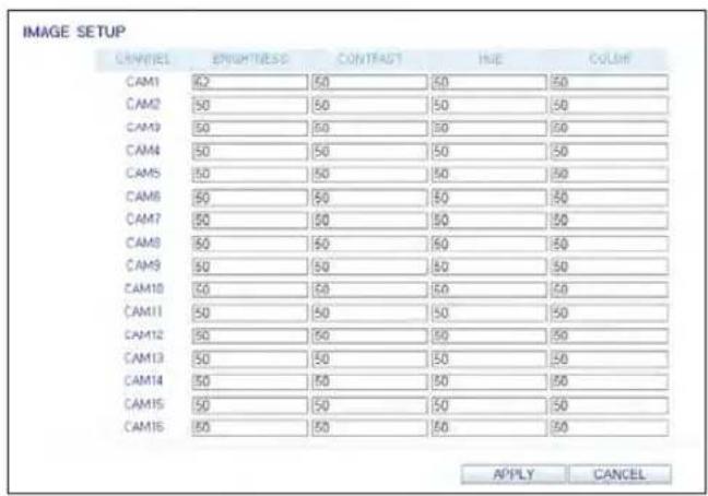
Covert Setting
You can set to hide the video of a specific camera from a specific user. Set to hide the camera video so that a specific user or user group can not view. To change the covert settings from user group to user, move to the
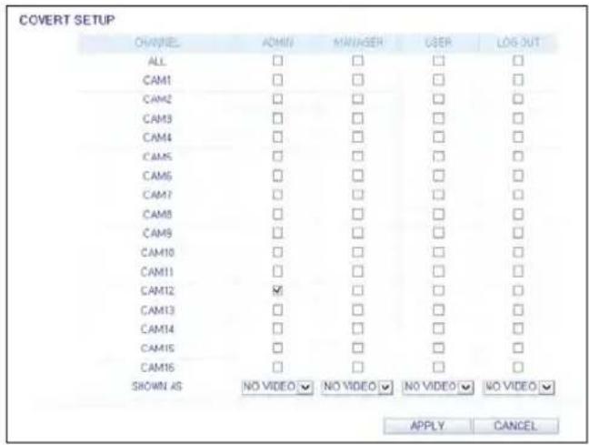
You can set each camera's motion detection, day/night time and others.
Select a channel. Set the mask area and activation and specify the daytime range.
When done, click
√ For information about how to set the motion area, refer to "Motion Area Setup". (page 36)
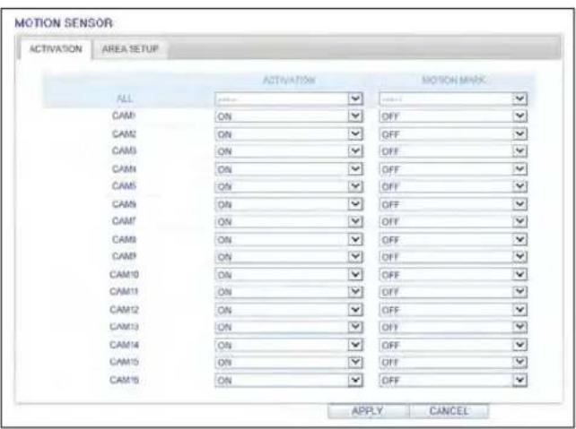
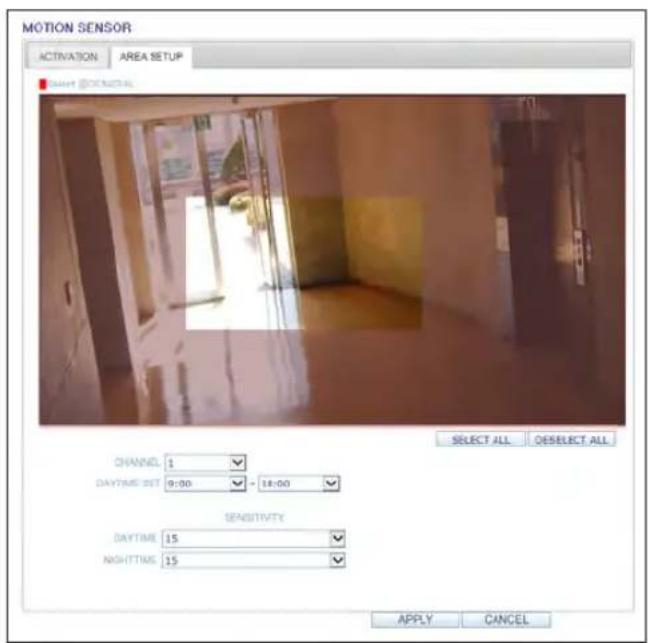
PTZ setting
To make DVR utilize cameras PTZ functions, match the protocol and baud rate of connected cameras and DVR.
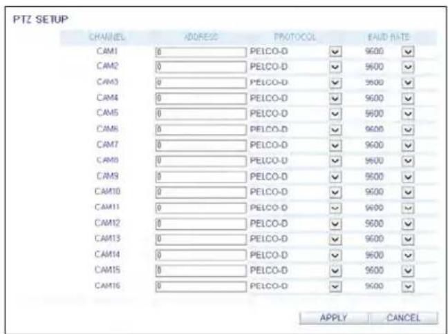
Web Viewer
Privacy Mask
You can enable a camera channel's privacy masking area and its mask color.
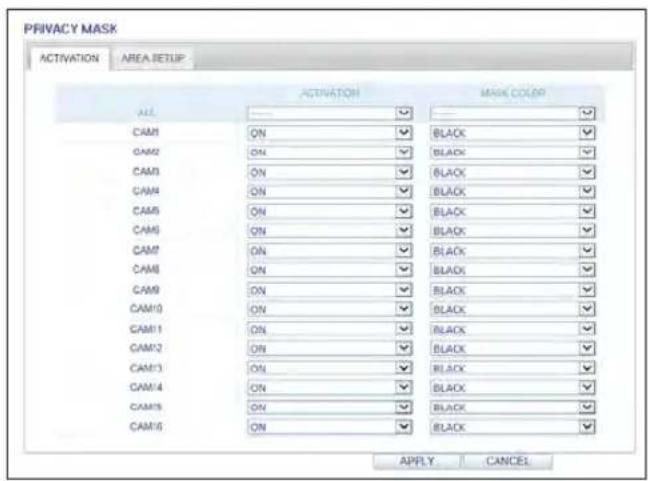
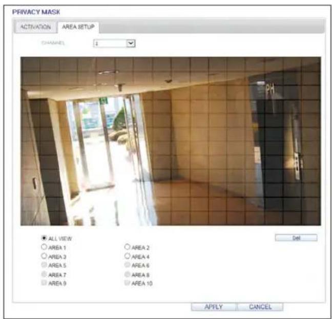
Display
OSD Setting
Configure the settings for the time, title, boundary, icon and language that will be displayed on the screen. Make changes to each item of the OSD menu and click
√ For details about each displayed item, refer to "OSD". (page 39)
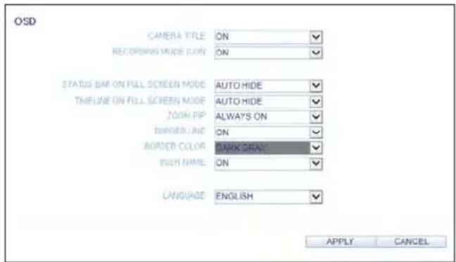
Monitor Settings
You can set the interval of an active sequence. Specify the interval and click
Sequence Dwell : Switching time from one channel to the next channel in single screen mode.
SPOT DWELL: It means the interval between the view types when displaying the SPOT Out monitoring screen.
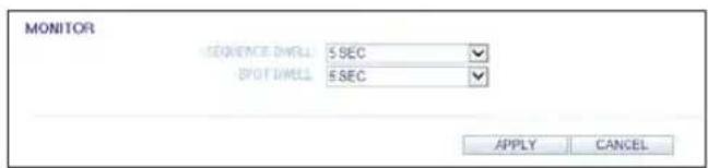
Audio
Audio/Buzzer
You can configure the settings of the voice and audio signal.
√ For details about each displayed item, refer to "Audio Setup". (page 47)
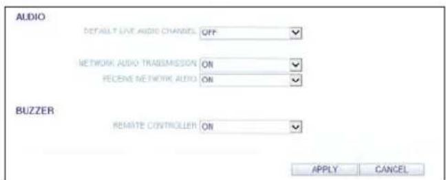
Web Viewer
User
User Management
You can add a user account and change the password.
√ For details about each displayed item, refer to "User Setting". (page 48)
To add a user, click
If you want to delete the user click next to it. When done, click
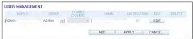
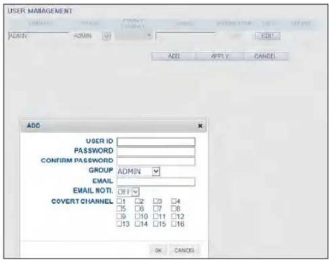
Group Permission Setting
You can grant different user groups different permissions to a specific menu.
Mark the checkboxes of the menu items accessible by the user group.
When done, click
√ For more information about the accessible menu items, refer to "Group Authority". (page 49)
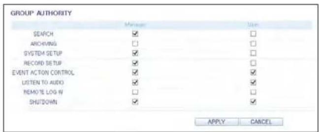
Network
Network Setting
You can check the network connection status and change the baud rate.
Change the maximum transfer rate and click
√ For more information about each network entry, refer to "IP Setup". (page 50)
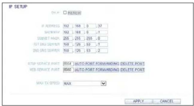
DDNS Setting
You can configure the DDNS settings so that remote users who are connected to the network can access remotely.
Change the DDNS settings and click
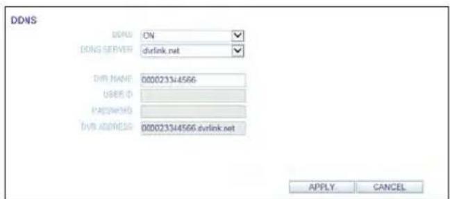
Email Setting
You can register and test an email address so that an email notification is delivered at a specific interval or if an event occurs.
Provide the necessary information and click
√ For more information, refer to "Email". (page 51)
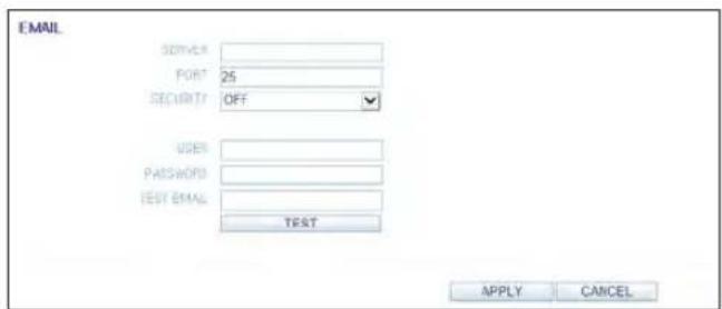
Web Viewer
System
Date/Time Setting
Specify the current date and time.
When done, click
√ For more information about each of the time and date settings, refer to "Date/Time". (page 53)
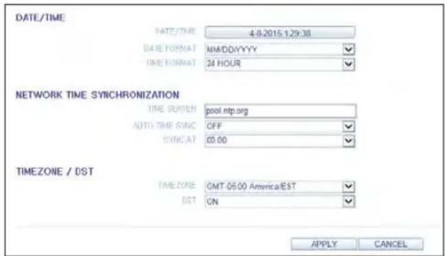
System Management
You can configure the access settings of: log in, log out, and auto logout.
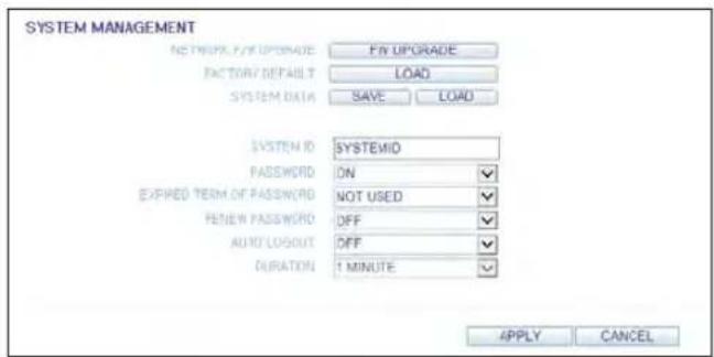
System Information
You can check information of system firmware version, disk space, and network settings, as well as the status information of network connection and alarm I/O.
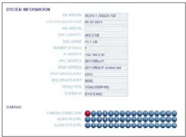
Control Device Setting
Set the connection of both the remote control and the keyboard control.
Change the communication settings and click
√ For more information about each communication item, refer to "Control Device". (page 57)
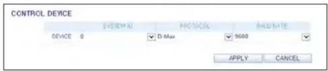
Storage
Device Information
You can check a list of internal/external storage devices connected to the DVR as well as the recording time information of each device.
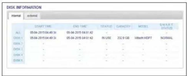
DISK Operations
You can set the overwrite mode and recording period of a storage device, or format the disk.
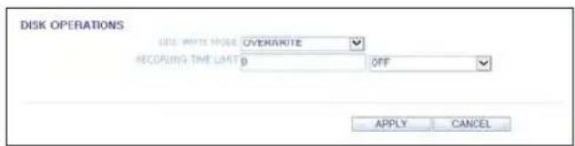
S.M.A.R.T Status
You can check the S.M.A.R.T status for each of the internal and external devices.
√ What is S.M.A.R.T? This is a sort of HDD self-diagnosis tool that detects any error on the system and alerts the user if an error occurs.
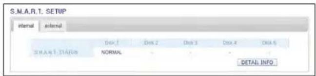
Web Viewer
Event
Alarm Output
Specify the alarm output conditions with the work schedule.
When done, click
√ For more information about the alarm output and ON/OFF schedule, refer to "Alarm Out". (page 63)
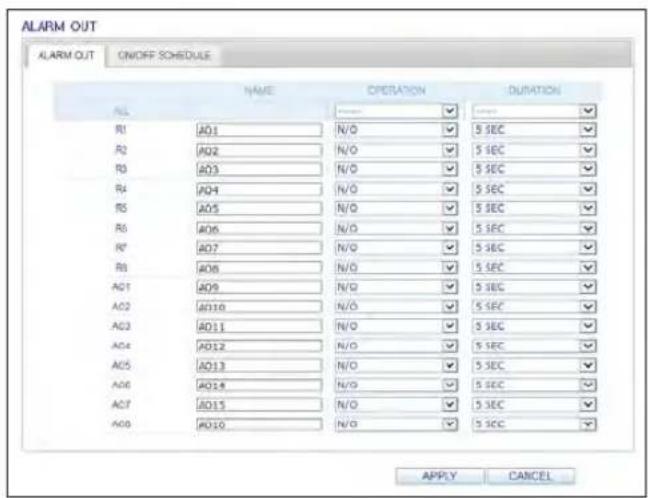
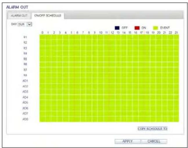
Event Notification
You can set desired event actions triggered by an event, such as
Set the dwell time for buzzer or pop-up display, or set the email or FTP destination settings and then click
√ For more information about the event notification, refer to "Event Notification". (page 65)
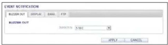
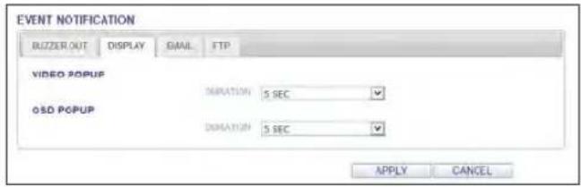
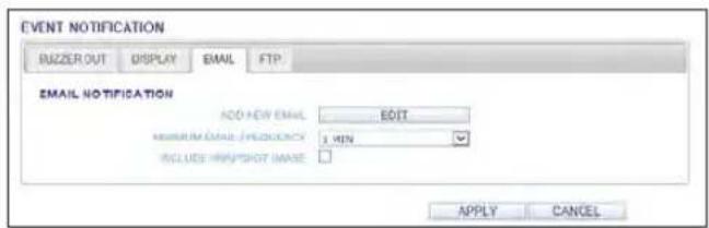
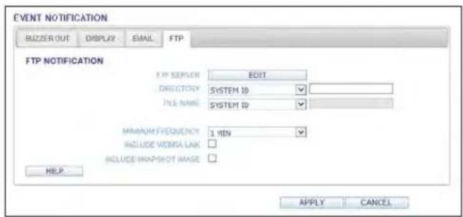
Web Viewer
Alarm Sensor
You can configure the settings of the alarm sensor and specify the operation of the sensor if an event occurs. When done, click
√ For more information about each of the alarm sensor actions, refer to "Alarm Sensor". (page 67)
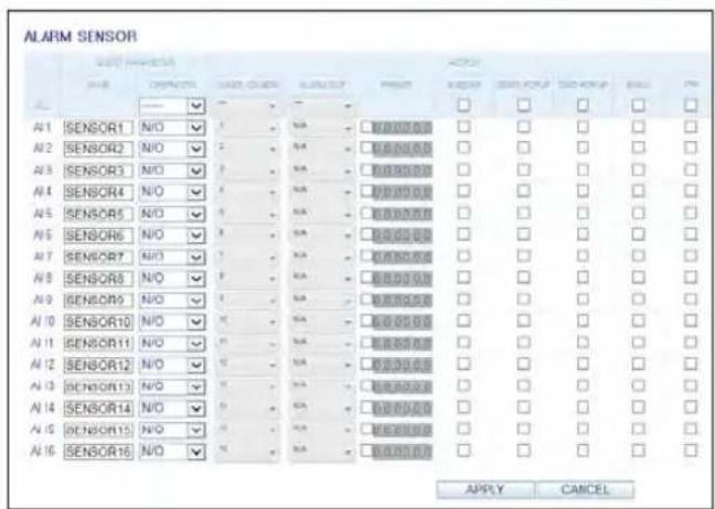
Motion Sensor
You can set an action to execute when a motion is detected.
When done, click
√ For more information about how to set the motion sensor, refer to "Motion Sensor". (page 68)
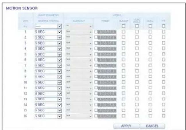
Video Loss
You can set to trigger alarm output or other actions when there is no video transfer from a camera. When done, click
√ For more information about how to set the video loss, refer to "Video Loss". (page 69)
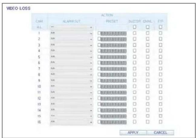
System Event
You can set event actions for disk, recording, network and system events. As same to setting event actions for normal events, you can set to trigger alarm output, buzzer, display on-screen pop-up, or send event notification via email and FTP.
When done, click
√ For more information about how to set the system event, refer to "System Event". (page 70)
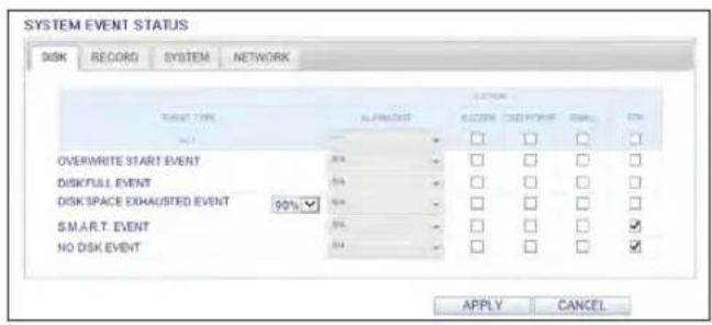
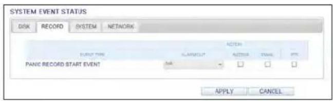
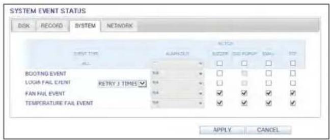
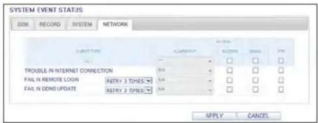
Web Viewer
Record Setup
Operation mode
You can set the recording options for AUTO CONFIGURATION or MANUAL CONFIGURATION mode.
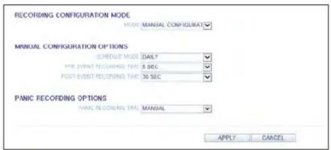
When done, click
√ For more information about how to set each mode, refer to "Operation Mode". (page 73)
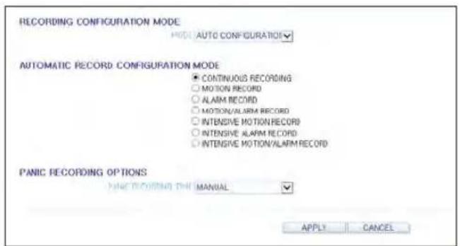
Continuous Recording
You can configure the settings of: continuous recording time, recording size, frame rate per second and quality. Click < ➕ next to each item to display the list of values available.
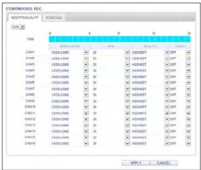
When you complete the recording size and schedule settings, click
√ For more information about the continuous recording size and schedule, refer to "Continuous Recording". (page 74)
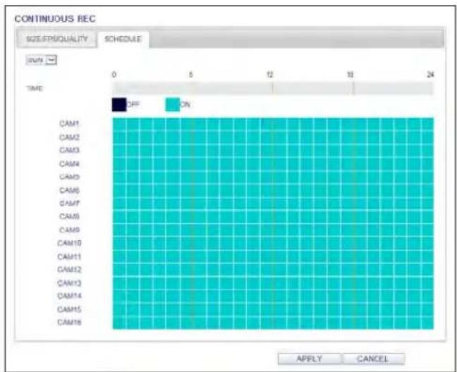
Web Viewer
Motion Recording
Set the
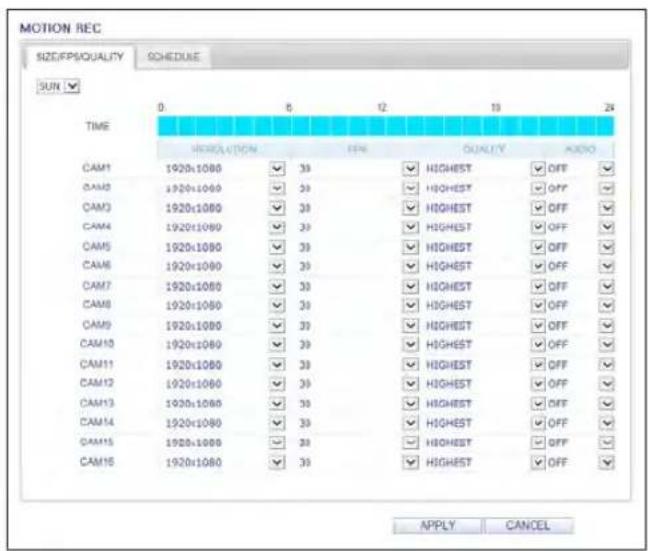
Complete setting the
√ For more information about the motion recording size and schedule, refer to "Motion Recording". (page 75)
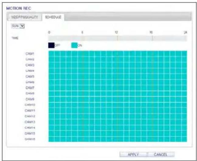
Alarm Recording
Set the
Click < next to each item to display the list of values available.
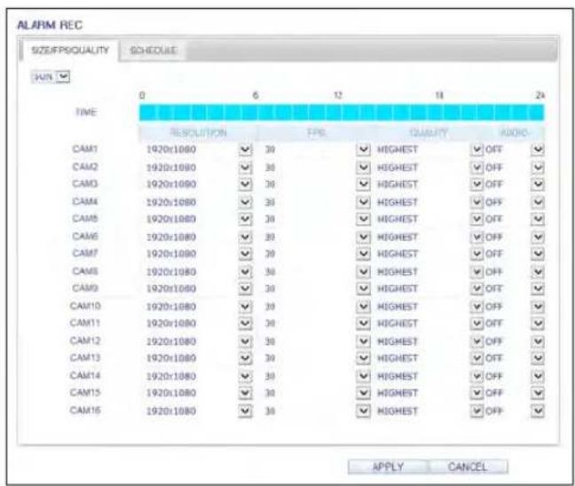
Complete setting the
√ For more information about the alarm recording size and schedule, refer to "Alarm Recording". (page 76)
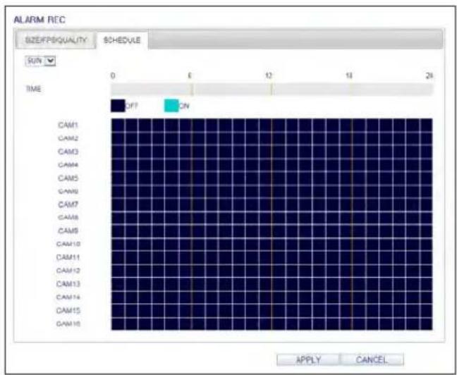
Web Viewer
Panic Recording
From the
Click < next to each item to display the list of values available.
When you have completed the manual record settings, click
√ For more information about the manual record settings, refer to "Panic Recording". (page 76)
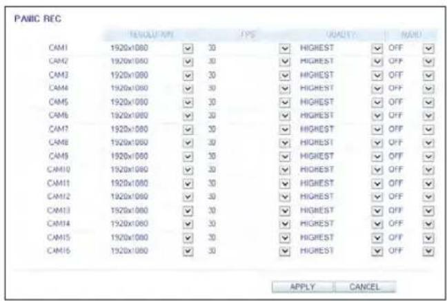
Network Streaming
You can specify the maximum size of network streaming and video resolution for remote users and change the FPS.
Click < next to each item to display the list of values available.
When done, click
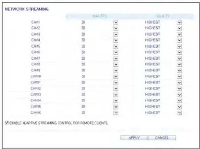
Audio Mapping
You can activate audio of a channel to communicate to the remote user.
Click < on the right side of each item to display audio channels available to select.
Click
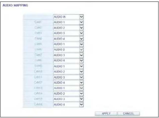
About
Click the
Web Viewer Information
DVR Model : 16CH / 480FPS
WEB Version : WEB_v2.7.3_1.0.0.50_140627
nViewer
You can use the smart viewer to monitor the network on a remote site and play the monitoring video anytime anywhere.
nViewer specification
Minimum / recommended specification
| OS Minimum specification Recommended specification | ||
| Android Phone | Processor : 800 MHz or higher | Processor : 1 GHz or higher |
| Flash : 512 MB or higher | Flash : 512 MB | |
| RAM : 512 MB or higher | RAM : 512 MB | |
| SD Card : 4 GB or higher | SD Card : 16 GB or higher | |
| OS : 2.0 or higher | OS : 2.1 or higher | |
| iPhone | iPhone 3G | iPhone 3GS or higher |
| iPod touch 3rd Generation | iPhone OS 3.2 or higher | |
| iPhone OS 3.1.3 or higher | ||
Using the nViewer on iPhone
How to download the iPhone-dedicated application
From your iPhone, access the App Store.
Enter "nViewer" in the search bar to find it before downloading. Install the application on your iPhone.
√ The nViewer supports the Multi split screen mode.
The nViewer Lite is a free application, and does not provide search, log view, PTZ control and system configuration functions.
To connect to DVR with nViewer
- Select and run the nViewer.
- Click < in the top right corner of the DVR List to select and add a site to the list.
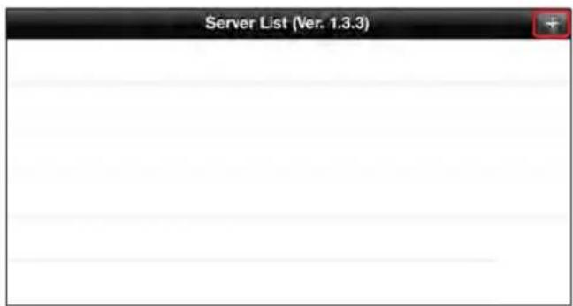
- Please enter a Name.
- Provide the IP address, HTTP port number and RTSP port number.
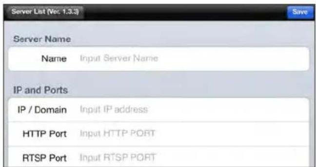

Mobile Viewer
- Provide the access ID of the DVR as well as the password.
- Specify the use of the Auto Login.
- Click
.
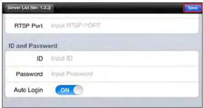
- Select the site that you added in the DVR List.
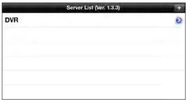
- Try to access the DVR. If connected successfully, you will see the screen as shown.
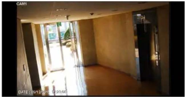
natural_image
Interior view of a modern building hallway with large windows and exposed doorways (no visible text or symbols)Split Mode
- Click any area on the screen. The main menu appears at the bottom of the screen.
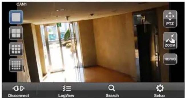
- Click < □> in the top left corner to switch to 1-split mode; click < □□□□> to switch to Multi-split mode.
√ Use the finger to scroll the screen to the left or right to move to the next camera video screen.
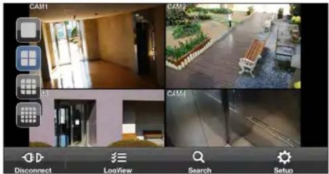

Mobile Viewer
To use PTZ control
- Click < PTZ > in the top right corner.
- Use buttons on the screen for PTZ control. (available only for cameras supporting PTZ functions.)
√ : Adjusts focus.
√ + - : Click the button to + - .
√ : Select one from the listed presets to run the selected preset action stored in the camera.
√ + : Activates Pan / Tilt toward the selected direction.
√: Captures the real-time video and saves as a still image in the handset's image folder.
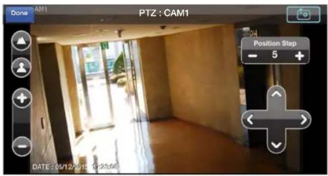
To use Zoom function
- Click < > in the top right corner.
- Click < + > button to zoom in, or click < - > to zoom out.
√ Touch the screen with two fingers and pinch open to zoom in, or pinch close to zoom out.
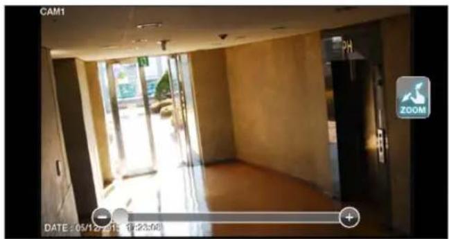
To view HQ (High Quality) video
7 Click < [REDA] > in the top right corner.
2. It switches to the HQ video.
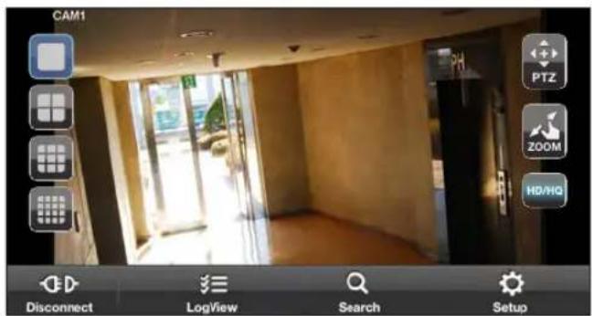
Using the Log View
- From the main menu, click < ☐. You can check the log of the data stored.
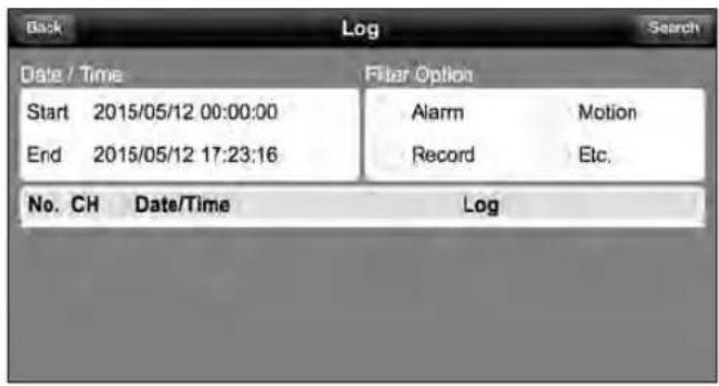
- Select one from Alarm, Motion, Record, Etc. and click < Search >. You will view the log of related items.
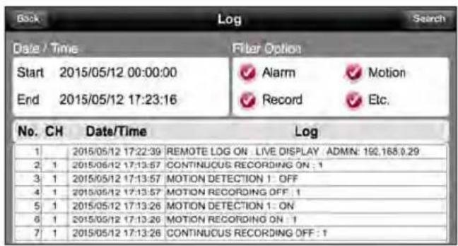

Mobile Viewer
Using the Search function
-
From the main menu, click <C. You can view the history of the data stored.
-
Select a desired time and date. You can use the vertical time bar to specify the start time.
-
Click < ▶ to play the video recorded at the specified time.
-
Click any area to display the play bar with which you can control the playing direction and speed of the video.
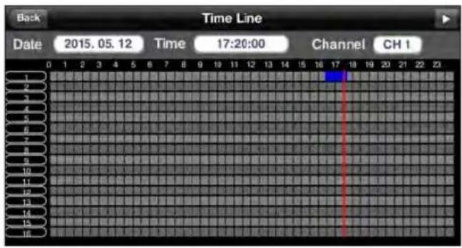
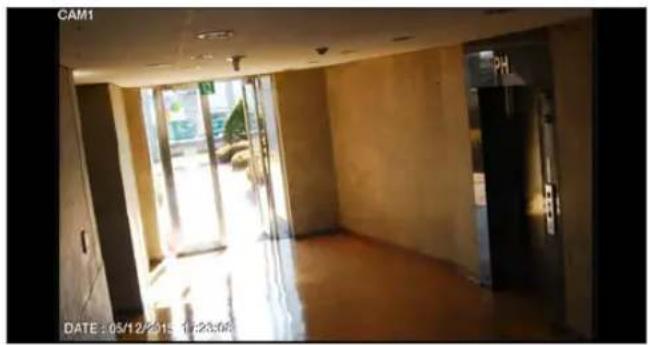
natural_image
Interior view of a modern building hallway with large windows and exposed floors (no visible text or symbols)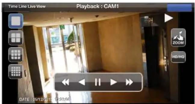
Using the Setup function
From the main menu, click <
You will be connected to the web viewer site.
√ For details about each displayed item, refer to "Setup". (page 98)
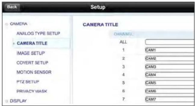
Mobile Viewer
Using nViewer with Android
How to download the Android-dedicated application
From your smart phone, access the Market.
Enter "nViewer" in the search bar to find it before downloading. Install the application on your Smart Phone.
√ The nViewer supports the 1/4 split screen mode.
The nViewer Lite is a free application, and does not provide search, log view, PTZ control and system configuration functions.
To connect to DVR with nViewer
- Select and run the nViewer.
- Use the Add button to select and add a site to the list.
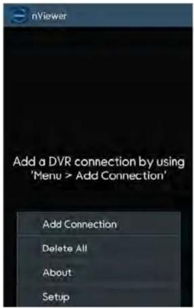
- Please enter a Name.
- Provide the IP address, HTTP port number and RTSP port number.
- Provide the access ID of the DVR as well as the password.
- Select whether or not to save the ID and PW.
- Click
.
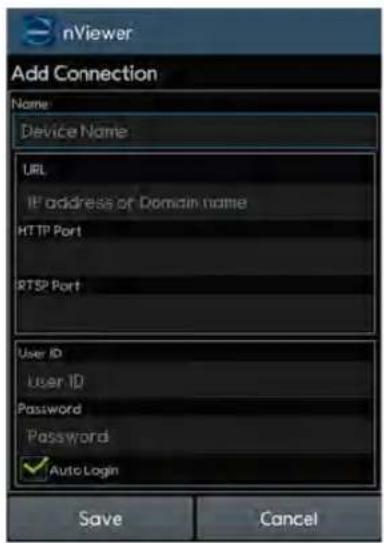
- Select the site that you added in the DVR List. Press and hold the mouse button to display the pop-up window.
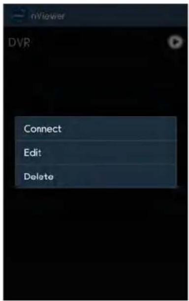
- Select
and try to access. If connected successfully, you will see the screen as shown.
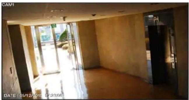
natural_image
Interior view of a modern building hallway with large windows and exposed floors (no visible text or symbols)
Mobile Viewer
Split Mode
- Click any area on the screen. The main menu appears at the bottom of the screen.
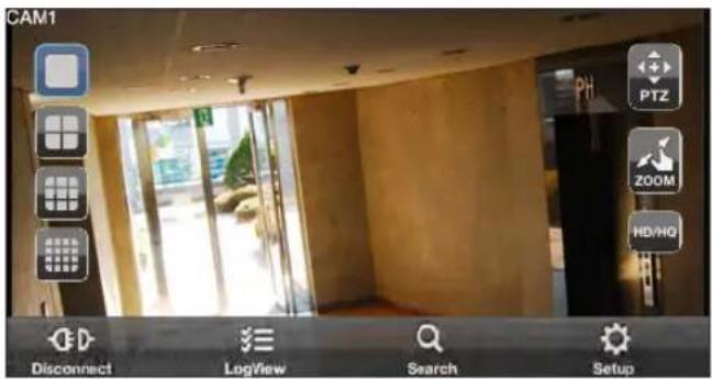
- Click < □> in the top left corner to switch to 1-split mode; click < □> to switch to Multi-split mode. √ Use the finger to scroll the screen to the left or right to move to the next camera video screen.
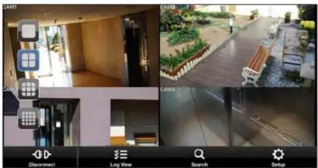
natural_image
Collage of four-panel image showing home security camera interface, interior view with mobile phones, outdoor garden path, and toolbar (no readable text or symbols)To use PTZ control
- Click < PTZ > in the top right corner.
- Use buttons on the screen for PTZ control. (available only for cameras supporting PTZ functions.)
√ + - : Adjusts focus.
√ + - : Click the button to + - .
√ : Select one from the listed presets to run the selected preset action stored in the camera.
√ + : Activates Pan / Tilt toward the selected direction.
√: Captures the real-time video and saves as a still image in the handset's image folder.
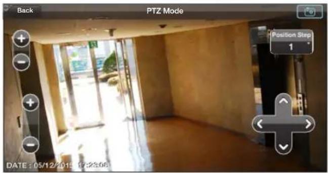
To use Zoom function
- Click < > in the top right corner.
- Click < + > button to zoom in, or click < - > to zoom out.
√ Touch the screen with two fingers and pinch open to zoom in, or pinch close to zoom out.
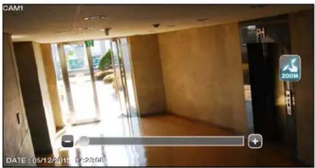
To view HQ (High Quality) video
- Click < 📄> in the top right corner.
- It switches to the HQ video.
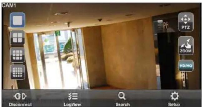
Mobile Viewer
Using the Log View
- From the main menu, click < ☐. You can check the log of the data stored.
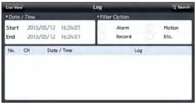
- Select one from Alarm, Motion, Record, Etc. and click < 🔒 >. You will view the log of related items.
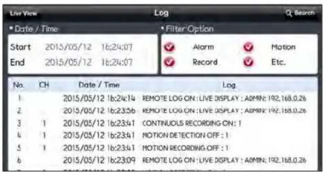
Using the Search function
- From the main menu, click < You can view the video of the recording data.
- Select a desired time and date. You can use the vertical time bar to specify the start time.
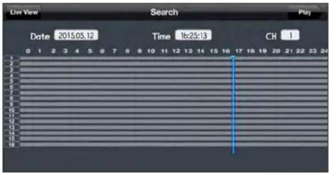
- Click < play the video recorded at the specified time.
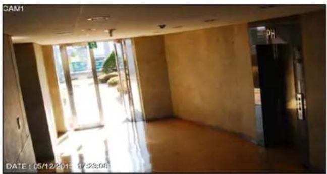
natural_image
Interior view of a modern building hallway with large windows and exposed flooring (no visible text or symbols)- Click any area to display the play bar with which you can control the playing direction and speed of the video.
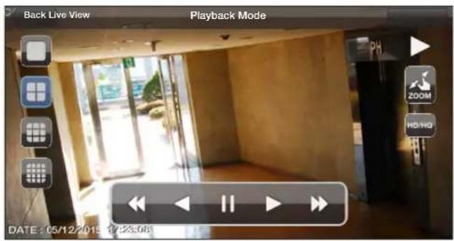
Mobile Viewer
Using the Setup function
From the main menu, click <. You will be connected to the web viewer site.
√ For details about each displayed item, refer to "Setup". (page 98)
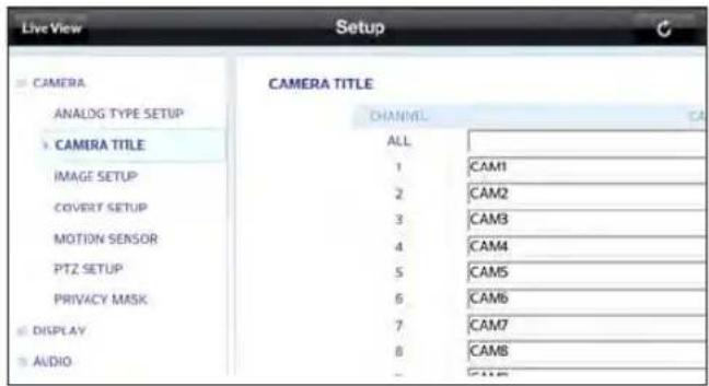
Archive Viewer
You can play the data archived in the DVR.
You can play the HDD data recorded by the DVR.
Getting started with the Backup Player
-
Connect the DVR to the backup USB storage device.
-
Open the folder saving the archived images.
-
Run the Backup Player.
-
Click <in the bottom left corner to display the file browser. Select the archived file to play.
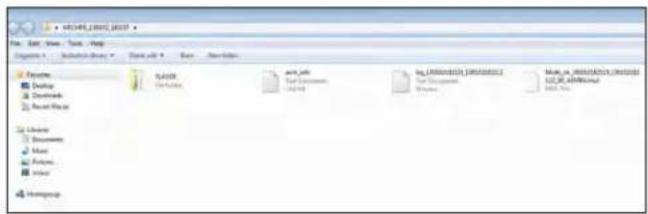
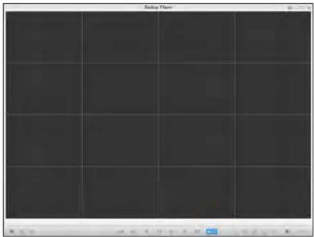
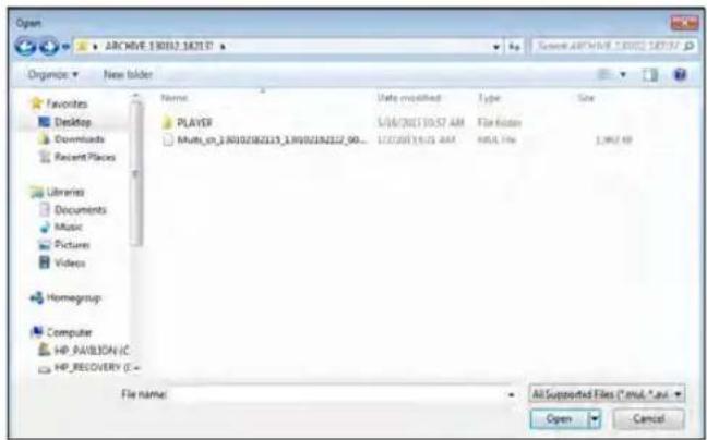
Archive Viewer
- Check the integrity of the archived file.
- When done, the archived file will be played on the screen.
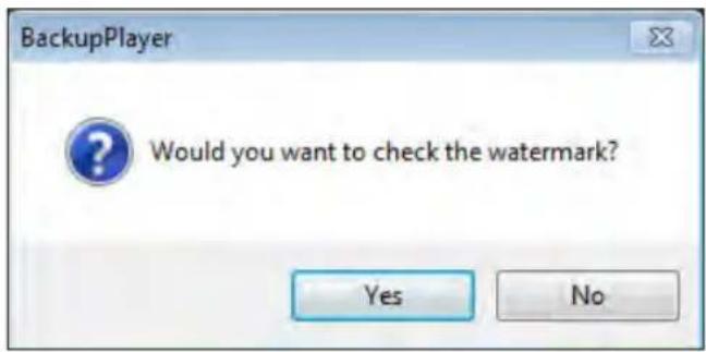
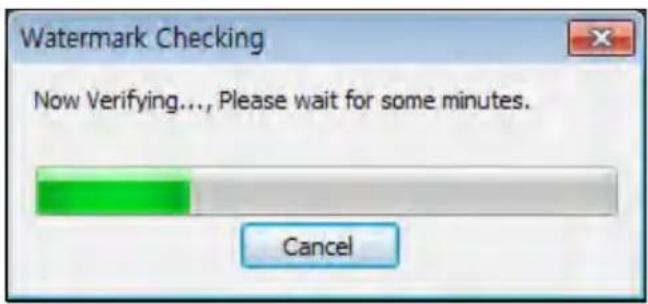
Backup Player At a Glance
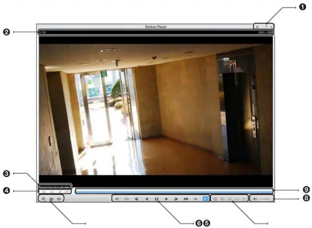
No. Item Description
| 1 | Setup Configure the environment settings. | |
| Minimize, Close Minimize or close the Backup Player. | ||
| 2 | Channel Information Show the channel information and the video resolution. | |
| 3 | Play Time Display the time of the current video image. | |
| 4 | Play Time Display the current playback time. | |
| File Search Open the file that you backed up. | ||
| 5 | Capture Capture the current screen. | |
| Print Print out the current screen. | ||
| 6 | Playback Control | Control the playback direction and speed of the current video.For more information about how to use the playback control buttons, refer to "Using the play bar". (page 84) |
| 7 | Zoom, Split Mode Switch to Zoom, 1-/4-/9-/16-split screen mode. | |
| 8 | Audio Setting Show the sound signal status and volume level. | |
| 9 | Play Bar Display the current playback position in the video. | |
Archive Viewer
Video Capture
Click < to capture the current video image.
Selected Video : Capture the actual frame of the current video.
Screen : Capture the visible portion of the current video.
Format : Select a saving format.(BMP, JPG, PNG)
Path : Specify the saving path.
- Default location : My Documents\My Pictures
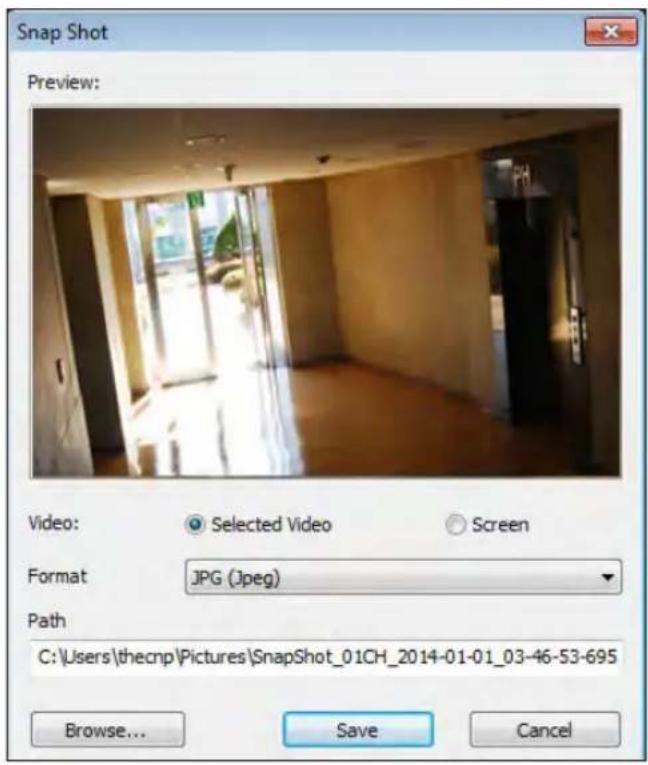
Print Out
Click < Button to print out the image.
When the "Print" window appears, check the preview and click
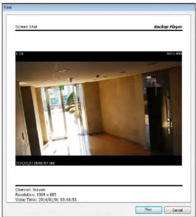
Settings
Click < ☐> to configure the Backup Player settings. You can check the version of the Backup Player.
Maintain image aspect ratio : Preserve the aspect ratio of the image. If you do not mark this option, the image will be adjusted to fit the screen.
I-frame Play : Only the I frames (key frames) will be playback.
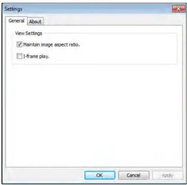
About : You can check the program information including the current version.
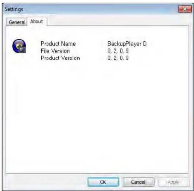
Appendix
Compatible HDD Specifications
| Maximum SATA Speed | ●SATA1(1.5G) : Can be used●SATA2(3.0G) : Can be used●SATA3(6.0G) : Devices of backward compatibility to SATA2 (3.0G) can be used. |
| Maximum Start-up Current 12V, 2A (or lower) | |
| Maximum Average Operation Power Consumption | 7W (or lower) |
| Maximum R/W Latency Latency (Read: 13ms / Write: 13ms) or smaller | |
√ Use 3.5" HDD disks.
√ Using HDD devices other than recommended specifications may cause serious problem.
√ For further information of HDD specifications, refer to the applicable data sheet of the HDD manufacturer.
Troubleshooting (FAQ)
| Problem Action | |
| The system does not operate at all with no active LED in the front panel. | Make sure that the rear switch is turned on.Make sure that the system gets supplied with power properly.Check the input voltage. |
| The unit continuously reboots. | Check if the system fan in a side panel of the unit or the CPU fan inside the unit works properly.If it fails, contact the retailer or the service center.Disconnect the HDD cable and try to boot the system again. If the system reboots successfully, install a new HDD and check if the system make recording normally. |
| The front LED is lit, but nothing is displayed on the screen yet. | Check if your monitor supports the 1080p 60Hz HDMI, VGA input.Ensure that the input source settings of the monitor match with the output source settings of the DVR.If using the HDMI-to-DVI cable for the connection, ensure that the input source is set to DVI.Make sure that the system gets supplied with power properly.Check the input voltage. |
| The sides of the video image are displayed incomplete. | If the monitor is over-scanning the video, the sides can be hidden.If this is the case, switch the display mode of the monitor to the 1:1 pixel matching mode. Then, you will view the video in full screen.The 1:1 pixel matching is referred to differently depending on the monitor manufacturer (for example, "JUST SCAN" for Samsung, "ZERO OVERSCAN" for LG). For details, refer to the user manual of the monitor. |
| The camera is connected but no image is displayed. | Make sure that the camera is compatible with the DVR. For the compatibility of the cameras, contact the retailer.Ensure that the output settings of the camera match with the camera type settings of the DVR. |
| It fails to connect to the web or mobile application. | Check if the network cable is properly connected to the WAN(UP Link) port of the unit.You must have set the port forwarding if using a router.If you cannot get access with the DDNS address, use the IP address of the DVR instead.If the DVR is connected to the router, use the IP address of the DVR.You can check the IP address of the router in- |
| I can access the web or mobile application but still no video image is displayed. | You must have set the port forwarding if using a router.This may happen when the communications provider or network administrator has blocked the service port of the DVR.Change the RTSP port and HTTP port numbers to different ones and set the port forwarding again.Try to access the web or mobile application using the new port numbers. |
Open Source License Report on the Product
The software included in this product contains copyrighted software that is licensed under the GPL/LGPL.
- GPL Software : linux kernel, busybox, cdrtools, dvd+rw-tools, smartctl, uboot, bash, udev, sysklogd
- LGPL Software : glibc, vmstat, glib, gtk, libESMTP, iconv, gstreamer, pango,
-OpenSSL License: OpenSSL
GNU GENERAL PUBLIC LICENSE
Version 2, June 1991
Copyright (C) 1989, 1991 Free Software Foundation, Inc.
51 Franklin Street, Fifth Floor, Boston, MA 02110-1301, USA
Everyone is permitted to copy and distribute verbatim copies of this license document, but changing it is not allowed.
Preamble
The licenses for most software are designed to take away your freedom to share and change it. By contrast, the GNU General Public License is intended to guarantee your freedom to share and change free software to make sure the software is free for all its users. This General Public License applies to most of the Free Software Foundation's software and to any other program whose authors commit to using it. (Some other Free Software Foundation software is covered by the GNU Lesser General Public License instead.) You can apply it to your programs, too.
When we speak of free software, we are referring to freedom, not price. Our General Public Licenses are designed to make sure that you have the freedom to distribute copies of free software (and charge for this service if you wish), that you receive source code or can get it if you want it, that you can change the software or use pieces of it in new free programs; and that you know you can do these things.
To protect your rights, we need to make restrictions that forbid anyone to deny you these rights or to ask you to surrender the rights. These restrictions translate to certain responsibilities for you if you distribute copies of the software, or if you modify it.
For example, if you distribute copies of such a program, whether gratis or for a fee, you must give the recipients all the rights that you have. You must make sure that they, too, receive or can get the source code. And you must show them these terms so they know their rights.
We protect your rights with two steps:
(1) copyright the software, and (2) offer you this license which gives you legal permission to copy, distribute and/or modify the software.
Also, for each author's protection and ours, we want to make certain that everyone understands that there is no warranty for this free software. If the software is modified by someone else and passed on, we want its recipients to know that what they have is not the original, so that any problems introduced by others will not reflect on the original authors' reputations.
Finally, any free program is threatened constantly by software patents. We wish to avoid the danger that redistributors of a free program will individually obtain patent licenses, in effect making the program proprietary. To prevent this, we have made it clear that any patent must be licensed for everyone's free use or not licensed at all. The precise terms and conditions for copying, distribution and modification follow.
TERMS AND CONDITIONS FOR COPYING, DISTRIBUTION AND MODIFICATION
Version 2, June 1991
Copyright (C) 1989, 1991 Free Software Foundation, Inc.
51 Franklin S
- This License applies to any program or other work which contains a notice placed by the copyright holder saying it may be distributed under the terms of this General Public License. The "Program", below, refers to any such program or work, and a "work based on the Program" means either the Program or any derivative work under copyright law: that is to say, a work containing the Program or a portion of it, either verbatim or with modifications and/or translated into another language. (Hereinafter, translation is included without limitation in the term "modification".) Each licensee is addressed as "you".
Activities other than copying, distribution and modification are not covered by this License; they are outside its scope. The act of running the Program is not restricted, and the output from the Program is covered only if its contents constitute a work based on the Program (independent of having been made by running the Program). Whether that is true depends on what the Program does.
- You may copy and distribute verbatim copies of the Program's source code as you receive it, in any medium, provided that you conspicuously and appropriately publish on each copy an appropriate copyright notice and disclaimer of warranty; keep intact all the notices that refer to this License and to the absence of any warranty; and give any other recipients of the Program a copy of this License along with the Program.
You may charge a fee for the physical act of transferring a copy, and you may at your option offer warranty protection in exchange for a fee.
- You may modify your copy or copies of the Program or any portion of it, thus forming a work based on the Program, and copy and distribute such modifications or work under the terms of Section 1 above, provided that you also meet all of these conditions:
a) You must cause the modified files to carry prominent notices stating that you changed the files and the date of any change.
b) You must cause any work that you distribute or publish, that in whole or in part contains or is derived from the Program or any part thereof, to be licensed as a whole at no charge to all third parties under the terms of this License.
c) If the modified program normally reads commands interactively when run, you must cause it, when started running for such interactive use in the most ordinary way, to print or display an announcement including an appropriate copyright notice and a notice that there is no warranty (or else, saying that you provide a warranty) and that users may redistribute the program under these conditions, and telling the user how to view a copy of this License. (Exception: if the Program itself is interactive but does not normally print such an announcement, your work based on the Program is not required to print an announcement.)
These requirements apply to the modified work as a whole. If identifiable sections of that work are not derived from the Program, and can be reasonably considered independent and separate works in themselves, then this License, and its terms, do not apply to those sections when you distribute them as separate works. But when you distribute the same sections as part of a whole which is a work based on the Program, the distribution of the whole must be on the terms of this License, whose permissions for other licensees extend to the entire whole, and thus to each and every part regardless of who wrote it.
Thus, it is not the intent of this section to claim rights or contest your rights to work written entirely by you; rather, the intent is to exercise the right to control the distribution of derivative or collective works based on the Program.
In addition, mere aggregation of another work not based on the Program with the Program (or with a work based on the Program) on a volume of a storage or distribution medium does not bring the other work under the scope of this License.
- You may copy and distribute the Program (or a work based on it, under Section 2) in object code or executable form under the terms of Sections 1 and 2 above provided that you also do one of the following:
a) Accompany it with the complete corresponding machine-readable source code, which must be distributed under the terms of Sections 1 and 2 above on a medium customarily used for software interchange; or,
b) Accompany it with a written offer, valid for at least three years, to give any third party, for a charge no more than your cost of physically performing source distribution, a complete machine-readable copy of the corresponding source code, to be distributed under the terms of Sections 1 and 2 above on a medium customarily used for software interchange; or,
c) Accompany it with the information you received as to the offer to distribute corresponding source code. (This alternative is allowed only for noncommercial distribution and only if you received the program in object code or executable form with such an offer, in accord with Subsection b above.)
The source code for a work means the preferred form of the work for making modifications to it. For an executable work, complete source code means all the source code for all modules it contains, plus any associated interface definition files, plus the scripts used to control compilation and installation of the executable. However, as a special exception, the source code distributed need not include anything that is normally distributed (in either source or binary form) with the major components (compiler, kemel, and so on) of the operating system on which the executable runs, unless that component itself accompanies the executable.
If distribution of executable or object code is made by offering access to copy from a designated place, then offering equivalent access to copy the source code from the same place counts as distribution of the source code, even though third parties are not compelled to copy the source along with the object code.
-
You may not copy, modify, sublicense, or distribute the Program except as expressly provided under this License. Any attempt otherwise to copy, modify, sublicense or distribute the Program is void, and will automatically terminate your rights under this License. However, parties who have received copies, or rights, from you under this License will not have their licenses terminated so long as such parties remain in full compliance.
-
You are not required to accept this License, since you have not signed it. However, nothing else grants you permission to modify or distribute the Program or its derivative works. These actions are prohibited by law if you do not accept this License. Therefore, by modifying or distributing the Program (or any work based on the Program), you indicate your acceptance of this License to do so, and all its terms and conditions for copying, distributing or modifying the Program or works based on it.
-
Each time you redistribute the Program (or any work based on the Program), the recipient automatically receives a license from the original licensor to copy, distribute or modify the Program subject to these terms and conditions. You may not impose any further restrictions on the recipients' exercise of the rights granted herein. You are not responsible for enforcing compliance by third parties to this License.
-
If, as a consequence of a court judgment or allegation of patent infringement or for any other reason (not limited to patent issues), conditions are imposed on you (whether by court order, agreement or otherwise) that contradict the conditions of this License, they do not excuse you from the conditions of this License. If you cannot distribute so as to satisfy simultaneously your obligations under this License and any other pertinent obligations, then as a consequence you may not distribute the Program at all. For example, if a patent license would not permit royalty-free redistribution of the Program by all those who receive copies directly or indirectly through you, then the only way you could satisfy both it and this License would be to refrain entirely from distribution of the Program.
If any portion of this section is held invalid or unenforceable under any particular circumstance, the balance of the section is intended to apply and the section as a whole is intended to apply in other circumstances.
It is not the purpose of this section to induce you to infringe any patents or other property right claims or to contest validity of any such claims; this section has the sole purpose of protecting the integrity of the free software distribution system, which is implemented by public license practices. Many people have made generous contributions to the wide range of software distributed through that system in reliance on consistent application of that system; it is up to the author/donor to decide if he or she is willing to distribute software through any other system and a licensee cannot impose that choice.
This section is intended to make thoroughly clear what is believed to be a consequence of the rest of this License.
-
If the distribution and/or use of the Program is restricted in certain countries either by patents or by copyrighted interfaces, the original copyright holder who places the Program under this License may add an explicit geographical distribution limitation excluding those countries, so that distribution is permitted only in or among countries not thus excluded. In such case, this License incorporates the limitation as if written in the body of this License.
-
The Free Software Foundation may publish revised and/or new versions of the General Public License from time to time. Such new versions will be similar in spirit to the present version, but may differ in detail to address new problems or concerns.
Each version is given a distinguishing version number. If the Program specifies a version number of this License which applies to it and “any later version”, you have the option of following the terms and conditions either of that version or of any later version published by the Free Software Foundation. If the Program does not specify a version number of this License, you may choose any version ever published by the Free Software Foundation.
- If you wish to incorporate parts of the Program into other free programs whose distribution conditions are different, write to the author to ask for permission. For software which is copyrighted by the Free Software Foundation, write to the Free Software Foundation; we sometimes make exceptions for this. Our decision will be guided by the two goals of preserving the free status of all derivatives of our free software and of promoting the sharing and reuse of software generally.
NO WARRANTY
-
BECAUSE THE PROGRAM IS LICENSED FREE OF CHARGE, THERE IS NO WARRANTY FOR THE PROGRAM, TO THE EXTENT PERMITTED BY APPLICABLE LAW. EXCEPT WHEN OTHERWISE STATED IN WRITING THE COPYRIGHT HOLDERS AND/OR OTHER PARTIES PROVIDE THE PROGRAM "AS IS" WITHOUT WARRANTY OF ANY KIND, EITHER EXPRESSED OR IMPLIED, INCLUDING, BUT NOT LIMITED TO, THE IMPLIED WARRANTIES OF MERCHANTABILITY AND FITNESS FOR A PARTICULAR PURPOSE. THE ENTIRE RISK AS TO THE QUALITY AND PERFORMANCE OF THE PROGRAM IS WITH YOU. SHOULD THE PROGRAM PROVE DEFECTIVE, YOU ASSUME THE COST OF ALL NECESSARY SERVICING, REPAIR OR CORRECTION.
-
IN NO EVENT UNLESS REQUIRED BY APPLICABLE LAW OR AGREED TO IN WRITING WILL ANY COPYRIGHT HOLDER, OR ANY OTHER PARTY WHO MAY MODIFY AND/OR REDISTRIBUTE THE PROGRAM AS PERMITTED ABOVE, BE LIABLE TO YOU FOR DAMAGES, INCLUDING ANY GENERAL, SPECIAL, INCIDENTAL OR CONSEQUENTIAL DAMAGES ARISING OUT OF THE USE OR INABILITY TO USE THE PROGRAM (INCLUDING BUT NOT LIMITED TO LOSS OF DATA OR DATA BEING RENDERED INACCURATE OR LOSSES SUSTAINED BY YOU OR THIRD PARTIES OR A FAILURE OF THE PROGRAM TO OPERATE WITH ANY OTHER PROGRAMS), EVEN IF SUCH HOLDER OR OTHER PARTY HAS BEEN ADVISED OF THE POSSIBILITY OF SUCH DAMAGES.
END OF TERMS AND CONDITIONS
How to Apply These Terms to Your New Programs
If you develop a new program, and you want it to be of the greatest possible use to the public, the best way to achieve this is to make it free software which everyone can redistribute and change under these terms.
To do so, attach the following notices to the program. It is safest to attach them to the start of each source file to most effectively convey the exclusion of warranty; and each file should have at least the “copyright” line and a pointer to where the full notice is found.
one line to give the program's name and an idea of what it does.
Copyright (C) yyyy name of author
This program is free software; you can redistribute it and/or modify it under the terms of the GNU General Public License as published by the Free Software Foundation; either version 2 of the License, or (at your option) any later version.
This program is distributed in the hope that it will be useful, but WITHOUT ANY WARRANTY; without even the implied warranty of MERCHANTABILITY or FITNESS FOR A PARTICULAR PURPOSE. See the GNU General Public License for more details.
You should have received a copy of the GNU General Public License along with this program; if not, write to the Free Software Foundation, Inc., 51 Franklin Street, Fifth Floor, Boston, MA 02110-1301, USA.
Also add information on how to contact you by electronic and paper mail. If the program is interactive, make it output a short notice like this when it starts in an interactive mode:
Gnomovision version 69, Copyright (C) year name of author Gnomovision comes with ABSOLUTELY NO WARRANTY; for details type 'show w'. This is free software, and you are welcome to redistribute it under certain conditions; type 'show c' for details.
The hypothetical commands 'show w' and 'show c' should show the appropriate parts of the General Public License. Of course, the commands you use may be called something other than 'show w' and 'show c'; they could even be mouse-clicks or menu items--whatever suits your program.
You should also get your employer (if you work as a programmer) or your school, if any, to sign a "copyright disclaimer" for the program, if necessary. Here is a sample; alter the names:
Yoyodyne, Inc., hereby disclaims all copyright interest in the program 'Gnomovision' (which makes passes at compilers) written by James Hacker.
signature of Ty Coon, 1 April 1989 Ty Coon, President of Vice This General Public License does not permit incorporating your program into proprietary programs. If your program is a subroutine library, you may consider it more useful to permit linking proprietary applications with the library. If this is what you want to do, use the GNU Lesser General Public License instead of this License.
GNU GENERAL PUBLIC LICENSE
Version 3, 29 June 2007
Copyright © 2007 Free Software Foundation, Inc. http://fsf.org/
Everyone is permitted to copy and distribute verbatim copies of this license document, but changing it is not allowed.
Preamble
The GNU General Public License is a free, copyleft license for software and other kinds of works.
The licenses for most software and other practical works are designed to take away your freedom to share and change the works. By contrast, the GNU General Public License is intended to guarantee your freedom to share and change all versions of a program--to make sure it remains free software for all its users. We, the Free Software Foundation, use the GNU General Public License for most of our software; it applies also to any other work released this way by its authors. You can apply it to your programs, too.
When we speak of free software, we are referring to freedom, not price. Our General Public Licenses are designed to make sure that you have the freedom to distribute copies of free software (and charge for them if you wish), that you receive source code or can get it if you want it, that you can change the software or use pieces of it in new free programs, and that you know you can do these things.
To protect your rights, we need to prevent others from denying you these rights or asking you to surrender the rights. Therefore, you have certain responsibilities if you distribute copies of the software, or if you modify it: responsibilities to respect the freedom of others.
For example, if you distribute copies of such a program, whether gratis or for a fee, you must pass on to the recipients the same freedoms that you received. You must make sure that they, too, receive or can get the source code. And you must show them these terms so they know their rights.
Developers that use the GNU GPL protect your rights with two steps: (1) assert copyright on the software, and (2) offer you this License giving you legal permission to copy, distribute and/or modify it.
For the developers' and authors' protection, the GPL clearly explains that there is no warranty for this free software. For both users' and authors' sake, the GPL requires that modified versions be marked as changed, so that their problems will not be attributed erroneously to authors of previous versions.
Some devices are designed to deny users access to install or run modified versions of the software inside them, although the manufacturer can do so. This is fundamentally incompatible with the aim of protecting users' freedom to change the software. The systematic pattern of such abuse occurs in the area of products for individuals to use, which is precisely where it is most unacceptable. Therefore, we have designed this version of the GPL to prohibit the practice for those products. If such problems arise substantially in other domains, we stand ready to extend this provision to those domains in future versions of the GPL, as needed to protect the freedom of users.
Finally, every program is threatened constantly by software patents. States should not allow patents to restrict development and use of software on general-purpose computers, but in those that do, we wish to avoid the special danger that patents applied to a free program could make it effectively proprietary. To prevent this, the GPL assures that patents cannot be used to render the program non-free.
The precise terms and conditions for copying, distribution and modification follow.
TERMS AND CONDITIONS
0. Definitions.
"This License" refers to version 3 of the GNU General Public License.
"Copyright" also means copyright-like laws that apply to other kinds of works, such as semiconductor masks.
"The Program" refers to any copyrightable work licensed under this License. Each licensee is addressed as "you". "Licensees" and "recipients" may be individuals or organizations.
To “modify” a work means to copy from or adapt all or part of the work in a fashion requiring copyright permission, other than the making of an exact copy. The resulting work is called a “modified version” of the earlier work or a work “based on” the earlier work.
A “covered work” means either the unmodified Program or a work based on the Program.
To “propagate” a work means to do anything with it that, without permission, would make you directly or secondarily liable for infringement under applicable copyright law, except executing it on a computer or modifying a private copy. Propagation includes copying, distribution (with or without modification), making available to the public, and in some countries other activities as well.
To “convey” a work means any kind of propagation that enables other parties to make or receive copies. Mere interaction with a user through a computer network, with no transfer of a copy, is not conveying.
An interactive user interface displays “Appropriate Legal Notices” to the extent that it includes a convenient and prominently visible feature that (1) displays an appropriate copyright notice, and (2) tells the user that there is no warranty for the work (except to the extent that warranties are provided), that licensees may convey the work under this License, and how to view a copy of this License. If the interface presents a list of user commands or options, such as a menu, a prominent item in the list meets this criterion.
1. Source Code.
The “source code” for a work means the preferred form of the work for making modifications to it. “Object code” means any non-source form of a work.
A "Standard Interface" means an interface that either is an official standard defined by a recognized standards body, or, in the case of interfaces specified for a particular programming language, one that is widely used among developers working in that language.
The “System Libraries” of an executable work include anything, other than the work as a whole, that (a) is included in the normal form of packaging a Major Component, but which is not part of that Major Component, and (b) serves only to enable use of the work with that Major Component, or to implement a Standard Interface for which an implementation is available to the public in source code form. A “Major Component”, in this context, means a major essential component (kernel, window system, and so on) of the specific operating system (if any) on which the executable work runs, or a compiler used to produce the work, or an object code interpreter used to run it.
The “Corresponding Source” for a work in object code form means all the source code needed to generate, install, and (for an executable work) run the object code and to modify the work, including scripts to control those activities. However, it does not include the work’s System Libraries, or general-purpose tools or generally available free programs which are used unmodified in performing those activities but which are not part of the work. For example, Corresponding Source includes interface definition files associated with source files for the work, and the source code for shared libraries and dynamically linked subprograms that the work is specifically designed to require, such as by intimate data communication or control flow between those subprograms and other parts of the work.
The Corresponding Source need not include anything that users can regenerate automatically from other parts of the Corresponding Source.
The Corresponding Source for a work in source code form is that same work.
2. Basic Permissions.
All rights granted under this License are granted for the term of copyright on the Program, and are irrevocable provided the stated conditions are met. This License explicitly affirms your unlimited permission to run the unmodified Program. The output from running a covered work is covered by this License only if the output, given its content, constitutes a covered work. This License acknowledges your rights of fair use or other equivalent, as provided by copyright law.
You may make, run and propagate covered works that you do not convey, without conditions so long as your license otherwise remains in force. You may convey covered works to others for the sole purpose of having them make modifications exclusively for you, or provide you with facilities for running those works, provided that you comply with the terms of this License in conveying all material for which you do not control copyright. Those thus making or running the covered works for you must do so exclusively on your behalf, under your direction and control, on terms that prohibit them from making any copies of your copyrighted material outside their relationship with you.
Conveying under any other circumstances is permitted solely under the conditions stated below. Sublicensing is not allowed; section 10 makes it unnecessary.
3. Protecting Users' Legal Rights From Anti-Circumvention Law.
No covered work shall be deemed part of an effective technological measure under any applicable law fulfilling obligations under article 11 of the WIPO copyright treaty adopted on 20 December 1996, or similar laws prohibiting or restricting circumvention of such measures.
When you convey a covered work, you waive any legal power to forbid circumvention of technological measures to the extent such circumvention is effected by exercising rights under this License with respect to the covered work, and you disclaim any intention to limit operation or modification of the work as a means of enforcing, against the work's users, your or third parties' legal rights to forbid circumvention of technological measures.
4. Conveying Verbatim Copies.
You may convey verbatim copies of the Program's source code as you receive it, in any medium, provided that you conspicuously and appropriately publish on each copy an appropriate copyright notice; keep intact all notices stating that this License and any non-permissive terms added in accord with section 7 apply to the code; keep intact all notices of the absence of any warranty; and give all recipients a copy of this License along with the Program.
You may charge any price or no price for each copy that you convey, and you may offer support or warranty protection for a fee.
5. Conveying Modified Source Versions.
You may convey a work based on the Program, or the modifications to produce it from the Program, in the form of source code under the terms of section 4, provided that you also meet all of these conditions:
a) The work must carry prominent notices stating that you modified it, and giving a relevant date.
b) The work must carry prominent notices stating that it is released under this License and any conditions added under section 7. This requirement modifies the requirement in section 4 to "keep intact all notices".
c) You must license the entire work, as a whole, under this License to anyone who comes into possession of a copy. This License will therefore apply, along with any applicable section 7 additional terms, to the whole of the work, and all its parts, regardless of how they are packaged. This License gives no permission to license the work in any other way, but it does not invalidate such permission if you have separately received it.
d) If the work has interactive user interfaces, each must display Appropriate Legal Notices; however, if the Program has interactive interfaces that do not display Appropriate Legal Notices, your work need not make them do so.
A compilation of a covered work with other separate and independent works, which are not by their nature extensions of the covered work, and which are not combined with it such as to form a larger program, in or on a volume of a storage or distribution medium, is called an "aggregate" if the compilation and its resulting copyright are not used to limit the access or legal rights of the compilation's users beyond what the individual works permit. Inclusion of a covered work in an aggregate does not cause this License to apply to the other parts of the aggregate.
6. Conveying Non-Source Forms.
You may convey a covered work in object code form under the terms of sections 4 and 5, provided that you also convey the machine-readable Corresponding Source under the terms of this License, in one of these ways:
a) Convey the object code in, or embodied in, a physical product (including a physical distribution medium), accompanied by the Corresponding Source fixed on a durable physical medium customarily used for software interchange.
b) Convey the object code in, or embodied in, a physical product (including a physical distribution medium), accompanied by a written offer, valid for at least three years and valid for as long as you offer spare parts or customer support for that product model, to give anyone who possesses the object code either (1) a copy of the Corresponding Source for all the software in the product that is covered by this License, on a durable physical medium customarily used for software interchange, for a price no more than your reasonable cost of physically performing this conveying of source, or (2) access to copy the Corresponding Source from a network server at no charge.
c) Convey individual copies of the object code with a copy of the written offer to provide the Corresponding Source. This alternative is allowed only occasionally and noncommercially, and only if you received the object code with such an offer, in accord with subsection 6b.
d) Convey the object code by offering access from a designated place (gratis or for a charge), and offer equivalent access to the Corresponding Source in the same way through the same place at no further charge. You need not require recipients to copy the Corresponding Source along with the object code. If the place to copy the object code is a network server, the Corresponding Source may be on a different server (operated by you or a third party) that supports equivalent copying facilities, provided you maintain clear directions next to the object code saying where to find the Corresponding Source. Regardless of what server hosts the Corresponding Source, you remain obligated to ensure that it is available for as long as needed to satisfy these requirements.
e) Convey the object code using peer-to-peer transmission, provided you inform other peers where the object code and Corresponding Source of the work are being offered to the general public at no charge under subsection 6d.
A separable portion of the object code, whose source code is excluded from the Corresponding Source as a System Library, need not be included in conveying the object code work.
A "User Product" is either (1) a "consumer product", which means any tangible personal property which is normally used for personal, family, or household purposes, or (2) anything designed or sold for incorporation into a dwelling. In determining whether a product is a consumer product, doubtful cases shall be resolved in favor of coverage. For a particular product received by a particular user, "normally used" refers to a typical or common use of that class of product, regardless of the status of the particular user or of the way in which the particular user actually uses, or expects or is expected to use, the product. A product is a consumer product regardless of whether the product has substantial commercial, industrial or non-consumer uses, unless such uses represent the only significant mode of use of the product.
“Installation Information” for a User Product means any methods, procedures, authorization keys, or other information required to install and execute modified versions of a covered work in that User Product from a modified version of its Corresponding Source. The information must suffice to ensure that the continued functioning of the modified object code is in no case prevented or interfered with solely because modification has been made.
If you convey an object code work under this section in, or with, or specifically for use in, a User Product, and the conveying occurs as part of a transaction in which the right of possession and use of the User Product is transferred to the recipient in perpetuity or for a fixed term (regardless of how the transaction is characterized), the Corresponding Source conveyed under this section must be accompanied by the Installation Information. But this requirement does not apply if neither you nor any third party retains the ability to install modified object code on the User Product (for example, the work has been installed in ROM).
The requirement to provide Installation Information does not include a requirement to continue to provide support service, warranty, or updates for a work that has been modified or installed by the recipient, or for the User Product in which it has been modified or installed. Access to a network may be denied when the modification itself materially and adversely affects the operation of the network or violates the rules and protocols for communication across the network.
Corresponding Source conveyed, and Installation Information provided, in accord with this section must be in a format that is publicly documented (and with an implementation available to the public in source code form), and must require no special password or key for unpacking, reading or copying.
7. Additional Terms.
"Additional permissions" are terms that supplement the terms of this License by making exceptions from one or more of its conditions. Additional permissions that are applicable to the entire Program shall be treated as though they were included in this License, to the extent that they are valid under applicable law. If additional permissions apply only to part of the Program, that part may be used separately under those permissions, but the entire Program remains governed by this License without regard to the additional permissions.
When you convey a copy of a covered work, you may at your option remove any additional permissions from that copy, or from any part of it. (Additional permissions may be written to require their own removal in certain cases when you modify the work.) You may place additional permissions on material, added by you to a covered work, for which you have or can give appropriate copyright permission.
Notwithstanding any other provision of this License, for material you add to a covered work, you may (if authorized by the copyright holders of that material) supplement the terms of this License with terms:
a) Disclaiming warranty or limiting liability differently from the terms of sections 15 and 16 of this License; or
b) Requiring preservation of specified reasonable legal notices or author attributions in that material or in the Appropriate Legal Notices displayed by works containing it; or
c) Prohibiting misrepresentation of the origin of that material, or requiring that modified versions of such material be marked in reasonable ways as different from the original version; or
d) Limiting the use for publicity purposes of names of licensors or authors of the material; or
e) Declining to grant rights under trademark law for use of some trade names, trademarks, or service marks; or
f) Requiring indemnification of licensors and authors of that material by anyone who conveys the material (or modified versions of it) with contractual assumptions of liability to the recipient, for any liability that these contractual assumptions directly impose on those licensors and authors.
All other non-permissive additional terms are considered “further restrictions” within the meaning of section 10. If the Program as you received it, or any part of it, contains a notice stating that it is governed by this License along with a term that is a further restriction, you may remove that term. If a license document contains a further restriction but permits relicensing or conveying under this License, you may add to a covered work material governed by the terms of that license document, provided that the further restriction does not survive such relicensing or conveying.
If you add terms to a covered work in accord with this section, you must place, in the relevant source files, a statement of the additional terms that apply to those files, or a notice indicating where to find the applicable terms.
Additional terms, permissive or non-permissive, may be stated in the form of a separately written license, or stated as exceptions; the above requirements apply either way.
8. Termination.
You may not propagate or modify a covered work except as expressly provided under this License. Any attempt otherwise to propagate or modify it is void, and will automatically terminate your rights under this License (including any patent licenses granted under the third paragraph of section 11).
However, if you cease all violation of this License, then your license from a particular copyright holder is reinstated (a) provisionally, unless and until the copyright holder explicitly and finally terminates your license, and (b) permanently, if the copyright holder fails to notify you of the violation by some reasonable means prior to 60 days after the cessation.
Moreover, your license from a particular copyright holder is reinstated permanently if the copyright holder notifies you of the violation by some reasonable means, this is the first time you have received notice of violation of this License (for any work) from that copyright holder, and you cure the violation prior to 30 days after your receipt of the notice.
Termination of your rights under this section does not terminate the licenses of parties who have received copies or rights from you under this License. If your rights have been terminated and not permanently reinstated, you do not qualify to receive new licenses for the same material under section 10.
9. Acceptance Not Required for Having Copies.
You are not required to accept this License in order to receive or run a copy of the Program. Ancillary propagation of a covered work occurring solely as a consequence of using peer-to-peer transmission to receive a copy likewise does not require acceptance. However, nothing other than this License grants you permission to propagate or modify any covered work. These actions infringe copyright if you do not accept this License. Therefore, by modifying or propagating a covered work, you indicate your acceptance of this License to do so.
10. Automatic Licensing of Downstream Recipients.
Each time you convey a covered work, the recipient automatically receives a license from the original licensors, to run, modify and propagate that work, subject to this License. You are not responsible for enforcing compliance by third parties with this License.
An “entity transaction” is a transaction transferring control of an organization, or substantially all assets of one, or subdividing an organization, or merging organizations. If propagation of a covered work results from an entity transaction, each party to that transaction who receives a copy of the work also receives whatever licenses to the work the party’s predecessor in interest had or could give under the previous paragraph, plus a right to possession of the Corresponding Source of the work from the predecessor in interest, if the predecessor has it or can get it with reasonable efforts.
You may not impose any further restrictions on the exercise of the rights granted or affirmed under this License. For example, you may not impose a license fee, royalty, or other charge for exercise of rights granted under this License, and you may not initiate litigation (including a cross-claim or counterclaim in a lawsuit) alleging that any patent claim is infringed by making, using, selling, offering for sale, or importing the Program or any portion of it.
11. Patents.
A "contributor" is a copyright holder who authorizes use under this License of the Program or a work on which the Program is based. The work thus licensed is called the contributor's "contributor version".
A contributor's “essential patent claims” are all patent claims owned or controlled by the contributor, whether already acquired or hereafter acquired, that would be infringed by some manner, permitted by this License, of making, using, or selling its contributor version, but do not include claims that would be infringed only as a consequence of further modification of the contributor version. For purposes of this definition, “control” includes the right to grant patent sublicenses in a manner consistent with the requirements of this License.
Each contributor grants you a non-exclusive, worldwide, royalty-free patent license under the contributor's essential patent claims, to make, use, sell, offer for sale, import and otherwise run, modify and propagate the contents of its contributor version.
In the following three paragraphs, a “patent license” is any express agreement or commitment, however denominated, not to enforce a patent (such as an express permission to practice a patent or covenant not to sue for patent infringement). To “grant” such a patent license to a party means to make such an agreement or commitment not to enforce a patent against the party.
If you convey a covered work, knowingly relying on a patent license, and the Corresponding Source of the work is not available for anyone to copy, free of charge and under the terms of this License, through a publicly available network server or other readily accessible means, then you must either (1) cause the Corresponding Source to be so available, or (2) arrange to deprive yourself of the benefit of the patent license for this particular work, or (3) arrange, in a manner consistent with the requirements of this License, to extend the patent license to downstream recipients. "Knowingly relying" means you have actual knowledge that, but for the patent license, your conveying the covered work in a country, or your recipient's use of the covered work in a country, would infringe one or more identifiable patents in that country that you have reason to believe are valid.
If, pursuant to or in connection with a single transaction or arrangement, you convey, or propagate by procuring conveyance of, a covered work, and grant a patent license to some of the parties receiving the covered work authorizing them to use, propagate, modify or convey a specific copy of the covered work, then the patent license you grant is automatically extended to all recipients of the covered work and works based on it.
A patent license is “discriminatory” if it does not include within the scope of its coverage, prohibits the exercise of, or is conditioned on the non-exercise of one or more of the rights that are specifically granted under this License. You may not convey a covered work if you are a party to an arrangement with a third party that is in the business of distributing software, under which you make payment to the third party based on the extent of your activity of conveying the work, and under which the third party grants, to any of the parties who would receive the covered work from you, a discriminatory patent license (a) in connection with copies of the covered work conveyed by you (or copies made from those copies), or (b) primarily for and in connection with specific products or compilations that contain the covered work, unless you entered into that arrangement, or that patent license was granted, prior to 28 March 2007.
Nothing in this License shall be construed as excluding or limiting any implied license or other defenses to infringement that may otherwise be available to you under applicable patent law.
12. No Surrender of Others' Freedom.
If conditions are imposed on you (whether by court order, agreement or otherwise) that contradict the conditions of this License, they do not excuse you from the conditions of this License. If you cannot convey a covered work so as to satisfy simultaneously your obligations under this License and any other pertinent obligations, then as a consequence you may not convey it at all. For example, if you agree to terms that obligate you to collect a royalty for further conveying from those to whom you convey the Program, the only way you could satisfy both those terms and this License would be to refrain entirely from conveying the Program.
13. Use with the GNU Affero General Public License.
Notwithstanding any other provision of this License, you have permission to link or combine any covered work with a work licensed under version 3 of the GNU Affero General Public License into a single combined work, and to convey the resulting work. The terms of this License will continue to apply to the part which is the covered work, but the special requirements of the GNU Affero General Public License, section 13, concerning interaction through a network will apply to the combination as such.
14. Revised Versions of this License.
The Free Software Foundation may publish revised and/or new versions of the GNU General Public License from time to time. Such new versions will be similar in spirit to the present version, but may differ in detail to address new problems or concerns.
Each version is given a distinguishing version number. If the Program specifies that a certain numbered version of the GNU General Public License "or any later version" applies to it, you have the option of following the terms and conditions either of that numbered version or of any later version published by the Free Software Foundation. If the Program does not specify a version number of the GNU General Public License, you may choose any version ever published by the Free Software Foundation.
If the Program specifies that a proxy can decide which future versions of the GNU General Public License can be used, that proxy's public statement of acceptance of a version permanently authorizes you to choose that version for the Program.
Later license versions may give you additional or different permissions. However, no additional obligations are imposed on any author or copyright holder as a result of your choosing to follow a later version.
15. Disclaimer of Warranty.
THERE IS NO WARRANTY FOR THE PROGRAM, TO THE EXTENT PERMITTED BY APPLICABLE LAW. EXCEPT WHEN OTHERWISE STATED IN WRITING THE COPYRIGHT HOLDERS AND/OR OTHER PARTIES PROVIDE THE PROGRAM "AS IS" WITHOUT WARRANTY OF ANY KIND, EITHER EXPRESSED OR IMPLIED, INCLUDING, BUT NOT LIMITED TO, THE IMPLIED WARRANTIES OF MERCHANTABILITY AND FITNESS FOR A PARTICULAR PURPOSE. THE ENTIRE RISK AS TO THE QUALITY AND PERFORMANCE OF THE PROGRAM IS WITH YOU. SHOULD THE PROGRAM PROVE DEFECTIVE, YOU ASSUME THE COST OF ALL NECESSARY SERVICING, REPAIR OR CORRECTION.
16. Limitation of Liability.
IN NO EVENT UNLESS REQUIRED BY APPLICABLE LAW OR AGREED TO IN WRITING WILL ANY COPYRIGHT HOLDER, OR ANY OTHER PARTY WHO MODIFIES AND/OR CONVEYS THE PROGRAM AS PERMITTED ABOVE, BE LIABLE TO YOU FOR DAMAGES, INCLUDING ANY GENERAL, SPECIAL, INCIDENTAL OR CONSEQUENTIAL DAMAGES ARISING OUT OF THE USE OR INABILITY TO USE THE PROGRAM (INCLUDING BUT NOT LIMITED TO LOSS OF DATA OR DATA BEING RENDERED INACCURATE OR LOSSES SUSTAINED BY YOU OR THIRD PARTIES OR A FAILURE OF THE PROGRAM TO OPERATE WITH ANY OTHER PROGRAMS), EVEN IF SUCH HOLDER OR OTHER PARTY HAS BEEN ADVISED OF THE POSSIBILITY OF SUCH DAMAGES.
17. Interpretation of Sections 15 and 16.
If the disclaimer of warranty and limitation of liability provided above cannot be given local legal effect according to their terms, reviewing courts shall apply local law that most closely approximates an absolute waiver of all civil liability in connection with the Program, unless a warranty or assumption of liability accompanies a copy of the Program in return for a fee.
END OF TERMS AND CONDITIONS
GNU LESSER GENERAL PUBLIC LICENSE
Version 2.1, February 1999
Copyright (C) 1991, 1999 Free Software Foundation, Inc.
51 Franklin Street, Fifth Floor, Boston, MA 02110-1301 USA
Everyone is permitted to copy and distribute verbatim copies of this license document, but changing it is not allowed.
This is the first released version of the Lesser GPL.
It also counts as the successor of the GNU Library Public License, version
2, hence the version number 2.1.]
Preamble
The licenses for most software are designed to take away your freedom to share and change it. By contrast, the GNU General Public Licenses are intended to guarantee your freedom to share and change free software to make sure the software is free for all its users.
This license, the Lesser General Public License, applies to some specially designated software packages--typically libraries--of the Free Software Foundation and other authors who decide to use it. You can use it too, but we suggest you first think carefully about whether this license or the ordinary General Public License is the better strategy to use in any particular case, based on the explanations below.
When we speak of free software, we are referring to freedom of use, not price. Our General Public Licenses are designed to make sure that you have the freedom to distribute copies of free software (and charge for this service if you wish); that you receive source code or can get it if you want it; that you can change the software and use pieces of it in new free
programs; and that you are informed that you can do these things.
To protect your rights, we need to make restrictions that forbid distributors to deny you these rights or to ask you to surrender these rights. These restrictions translate to certain responsibilities for you if you distribute copies of the library or if you modify it.
For example, if you distribute copies of the library, whether gratis or for a fee, you must give the recipients all the rights that we gave you. You must make sure that they, too, receive or can get the source code. If you link other code with the library, you must provide complete object files to the recipients, so that they can relink them with the library after making changes to the library and recompiling it. And you must show them these terms so they know their rights.
We protect your rights with a two-step method: (1) we copyright the library, and (2) we offer you this license, which gives you legal permission to copy, distribute and/or modify the library.
To protect each distributor, we want to make it very clear that there is no warranty for the free library. Also, if the library is modified by someone else and passed on, the recipients should know that what they have is not the original version, so that the original author's reputation will not be affected by problems that might be introduced by others.
Finally, software patents pose a constant threat to the existence of any free program. We wish to make sure that a company cannot effectively restrict the users of a free program by obtaining a restrictive license from a patent holder. Therefore, we insist that any patent license obtained for a version of the library must be consistent with the full freedom of use specified in this license.
Most GNU software, including some libraries, is covered by the ordinary GNU General Public License. This license, the GNU Lesser General Public License, applies to certain designated libraries, and is quite different from the ordinary General Public License. We use this license for certain libraries in order to permit linking those libraries into non-free programs.
When a program is linked with a library, whether statically or using a shared library, the combination of the two is legally speaking a combined work, a derivative of the original library. The ordinary General Public License therefore permits such linking only if the entire combination fits its criteria of freedom. The Lesser General Public License permits more lax criteria for linking other code with the library.
We call this license the “Lesser” General Public License because it does Less to protect the user’s freedom than the ordinary General Public License. It also provides other free software developers Less of an advantage over competing non-free programs. These disadvantages are the reason we use the ordinary General Public License for many libraries. However, the Lesser license provides advantages in certain special circumstances.
For example, on rare occasions, there may be a special need to encourage the widest possible use of a certain library, so that it becomes a de-facto standard. To achieve this, non-free programs must be allowed to use the library. A more frequent case is that a free library does the same job as widely used non-free libraries. In this case, there is little to gain by limiting the free library to free software only, so we use the Lesser General Public License.
In other cases, permission to use a particular library in non-free programs enables a greater number of people to use a large body of free software. For example, permission to use the GNU C Library in non-free programs enables many more people to use the whole GNU operating system, as well as its variant, the GNU/Linux operating system.
Although the Lesser General Public License is Less protective of the users' freedom, it does ensure that the user of a program that is linked with the Library has the freedom and the wherewithal to run that program using a modified version of the Library.
The precise terms and conditions for copying, distribution and modification follow. Pay close attention to the difference between a “work based on the library” and a “work that uses the library”. The former contains code derived from the library, whereas the latter must be combined with the library in order to run.
TERMS AND CONDITIONS FOR COPYING, DISTRIBUTION AND MODIFICATION
- This License Agreement applies to any software library or other program which contains a notice placed by the copyright holder or other authorized party saying it may be distributed under the terms of this Lesser General Public License (also called "this License"). Each licensee is addressed as "you".
A "library" means a collection of software functions and/or data prepared so as to be conveniently linked with application programs (which use some of those functions and data) to form executables.
The “Library”, below, refers to any such software library or work which has been distributed under these terms. A “work based on the Library” means either the Library or any derivative work under copyright law: that is to say, a work containing the Library or a portion of it, either verbatim or with modifications and/or translated straightforwardly into another language. (Hereinafter, translation is included without limitation in the term “modification”).
“Source code” for a work means the preferred form of the work for making modifications to it. For a library, complete source code means all the source code for all modules it contains, plus any associated interface definition files, plus the scripts used to control compilation and installation of the library.
Activities other than copying, distribution and modification are not covered by this License; they are outside its scope. The act of running a program using the Library is not restricted, and output from such a program is covered only if its contents constitute a work based on the Library (independent of the use of the Library in a tool for writing it). Whether that is true depends on what the Library does and what the program that uses the Library does.
- You may copy and distribute verbatim copies of the Library's complete source code as you receive it, in any medium, provided that you conspicuously and appropriately publish on each copy an appropriate copyright notice and disclaimer of warranty; keep intact all the notices that refer to this License and to the absence of any warranty; and distribute a copy of this License along with the Library.
You may charge a fee for the physical act of transferring a copy, and you may at your option offer warranty protection in exchange for a fee.
- You may modify your copy or copies of the Library or any portion of it, thus forming a work based on the Library, and copy and distribute such modifications or work under the terms of Section 1 above, provided that you also meet all of these conditions:
a) The modified work must itself be a software library.
b) You must cause the files modified to carry prominent notices stating that you changed the files and the date of any change.
c) You must cause the whole of the work to be licensed at no charge to all third parties under the terms of this License.
d) If a facility in the modified Library refers to a function or a table of data to be supplied by an application program that uses the facility, other than as an argument passed when the facility is invoked, then you must make a good faith effort to ensure that, in the event an application does not supply such function or table, the facility still operates, and performs whatever part of its purpose remains meaningful.
(For example, a function in a library to compute square roots has a purpose that is entirely well-defined independent of the application. Therefore, Subsection 2d requires that any application-supplied function or table used by this function must be optional: if the application does not supply it, the square root function must still compute square roots.)
These requirements apply to the modified work as a whole. If identifiable sections of that work are not derived from the Library, and can be reasonably considered independent and separate works in themselves, then this License, and its terms, do not apply to those sections when you distribute them as separate works. But when you distribute the same sections as part of a whole which is a work based on the Library, the distribution of the whole must be on the terms of this License, whose permissions for other licensees extend to the entire whole, and thus to each and every part regardless of who wrote it.
Thus, it is not the intent of this section to claim rights or contest your rights to work written entirely by you; rather, the intent is to exercise the right to control the distribution of derivative or collective works based on the Library.
In addition, mere aggregation of another work not based on the Library with the Library (or with a work based on the Library) on a volume of a storage or distribution medium does not bring the other work under the scope of this License.
- You may opt to apply the terms of the ordinary GNU General Public License instead of this License to a given copy of the Library. To do this, you must alter all the notices that refer to this License, so that they refer to
the ordinary GNU General Public License, version 2, instead of to this License. (If a newer version than version 2 of the ordinary GNU General Public License has appeared, then you can specify that version instead if you wish.) Do not make any other change in these notices.
Once this change is made in a given copy, it is irreversible for that copy, so the ordinary GNU General Public License applies to all subsequent copies and derivative works made from that copy.
This option is useful when you wish to copy part of the code of the Library into a program that is not a library.
- You may copy and distribute the Library (or a portion or derivative of it, under Section 2) in object code or executable form under the terms of Sections 1 and 2 above provided that you accompany it with the complete corresponding machine-readable source code, which must be distributed under the terms of Sections 1 and 2 above on a medium customarily used for software interchange.
If distribution of object code is made by offering access to copy from a designated place, then offering equivalent access to copy the source code from the same place satisfies the requirement to distribute the source code, even though third parties are not compelled to copy the source along with the object code.
- A program that contains no derivative of any portion of the Library, but is designed to work with the Library by being compiled or linked with it, is called a "work that uses the Library". Such a work, in isolation, is not a derivative work of the Library, and therefore falls outside the scope of this License.
However, linking a “work that uses the Library” with the Library creates an executable that is a derivative of the Library (because it contains portions of the Library), rather than a “work that uses the library”. The executable is therefore covered by this License. Section 6 states terms for distribution of such executables.
When a “work that uses the Library” uses material from a header file that is part of the Library, the object code for the work may be a derivative work of the Library even though the source code is not. Whether this is true is especially significant if the work can be linked without the Library, or if the work is itself a library. The threshold for this to be true is not precisely defined by law.
If such an object file uses only numerical parameters, data structure layouts and accessors, and small macros and small inline functions (ten lines or less in length), then the use of the object file is unrestricted, regardless of whether it is legally a derivative work. (Executables containing this object code plus portions of the Library will still fall under Section 6.)
Otherwise, if the work is a derivative of the Library, you may distribute the object code for the work under the terms of Section 6. Any executables containing that work also fall under Section 6, whether or not they are linked directly with the Library itself.
- As an exception to the Sections above, you may also combine or link a "work that uses the Library" with the Library to produce a work containing portions of the Library, and distribute that work under terms of your choice, provided that the terms permit modification of the work for the customer's own use and reverse engineering for debugging such modifications.
You must give prominent notice with each copy of the work that the Library is used in it and that the Library and its use are covered by this License. You must supply a copy of this License. If the work during execution displays copyright notices, you must include the copyright notice for the Library among them, as well as a reference directing the user to the copy of this License. Also, you must do one of these things:
a) Accompany the work with the complete corresponding machine-readable source code for the Library including whatever changes were used in the work (which must be distributed under Sections 1 and 2 above); and, if the work is an executable linked with the Library, with the complete machine readable "work that uses the Library", as object code and/or source code, so that the user can modify the Library and then relink to produce a modified executable containing the modified Library. (It is understood that the user who changes the contents of definitions files in the Library will not necessarily be able to recompile the application to use the modified definitions.)
b) Use a suitable shared library mechanism for linking with the Library. A suitable mechanism is one that (1) uses at run time a copy of the library already present on the user's computer system, rather than copying library functions into the executable, and (2) will operate properly with a modified version of the library, if the user installs one, as long as the modified version is interface-compatible with the version that the work was made with.
c) Accompany the work with a written offer, valid for at least three years, to give the same user the materials specified in Subsection 6a, above, for a charge no more than the cost of performing this distribution.
d) If distribution of the work is made by offering access to copy from a designated place, offer equivalent access to copy the above specified materials from the same place.
e) Verify that the user has already received a copy of these materials or that you have already sent this user a copy.
For an executable, the required form of the "work that uses the Library" must include any data and utility programs needed for reproducing the executable from it. However, as a special exception, the materials to be distributed need not include anything that is normally distributed (in either source or binary form) with the major components (compiler, kernel, and so on) of the operating system on which the executable runs, unless that component itself accompanies the executable.
It may happen that this requirement contradicts the license restrictions of other proprietary libraries that do not normally accompany the operating system. Such a contradiction means you cannot use both them and the Library together in an executable that you distribute.
- You may place library facilities that are a work based on the Library side-by-side in a single library together with other library facilities not covered by this License, and distribute such a combined library, provided that the separate distribution of the work based on the Library and of the other library facilities is otherwise permitted, and provided that you do these two things:
a) Accompany the combined library with a copy of the same work based on the Library, uncombined with any other library facilities. This must be distributed under the terms of the Sections above.
b) Give prominent notice with the combined library of the fact that part of it is a work based on the Library, and explaining where to find the accompanying uncombined form of the same work.
- You may not copy, modify, sublicense, link with, or distribute the Library except as expressly provided under this License. Any attempt otherwise to copy, modify, sublicense, link with, or distribute the Library is void, and will automatically terminate your rights under this License. However, parties who have received copies, or rights, from you under this License will not have their licenses terminated so long as such parties remain in full compliance.
- You are not required to accept this License, since you have not signed it. However, nothing else grants you permission to modify or distribute the Library or its derivative works. These actions are prohibited by law if you do not accept this License. Therefore, by modifying or distributing the Library (or any work based on the Library), you indicate your acceptance of this License to do so, and all its terms and conditions for copying, distributing or modifying the Library or works based on it.
- Each time you redistribute the Library (or any work based on the Library), the recipient automatically receives a license from the original licensor to copy, distribute, link with or modify the Library subject to these terms and conditions. You may not impose any further restrictions on the recipients' exercise of the rights granted herein. You are not responsible for enforcing compliance by third parties with this License.
- If, as a consequence of a court judgment or allegation of patent infringement or for any other reason (not limited to patent issues), conditions are imposed on you (whether by court order, agreement or otherwise) that contradict the conditions of this License, they do not excuse you from the conditions of this License. If you cannot distribute so as to satisfy simultaneously your obligations under this License and any other pertinent obligations, then as a consequence you may not distribute
the Library at all. For example, if a patent license would not permit royalty free redistribution of the Library by all those who receive copies directly or indirectly through you, then the only way you could satisfy both it and this License would be to refrain entirely from distribution of the Library.
If any portion of this section is held invalid or unenforceable under any particular circumstance, the balance of the section is intended to apply, and the section as a whole is intended to apply in other circumstances.
It is not the purpose of this section to induce you to infringe any patents or other property right claims or to contest validity of any such claims; this section has the sole purpose of protecting the integrity of the free software distribution system which is implemented by public license practices. Many people have made generous contributions to the wide range of software distributed through that system in reliance on consistent application of that system; it is up to the author/donor to decide if he or she is willing to distribute software through any other system and a licensee cannot impose that choice.
This section is intended to make thoroughly clear what is believed to be a consequence of the rest of this License.
- If the distribution and/or use of the Library is restricted in certain countries either by patents or by copyrighted interfaces, the original copyright holder who places the Library under this License may add an explicit geographical distribution limitation excluding those countries, so that distribution is permitted only in or among countries not thus excluded. In such case, this License incorporates the limitation as if written in the body of this License.
- The Free Software Foundation may publish revised and/or new versions of the Lesser General Public License from time to time. Such new versions will be similar in spirit to the present version, but may differ in detail to address new problems or concerns.
Each version is given a distinguishing version number. If the Library specifies a version number of this License which applies to it and "any later version", you have the option of following the terms and conditions either of that version or of any later version published by the Free Software Foundation. If the Library does not specify a license version number, you may choose any version ever published by the Free Software Foundation.
- If you wish to incorporate parts of the Library into other free programs whose distribution conditions are incompatible with these, write to the author to ask for permission. For software which is copyrighted by the Free Software Foundation, write to the Free Software Foundation; we sometimes make exceptions for this. Our decision will be guided by the two goals of preserving the free status of all derivatives of our free software and of promoting the sharing and reuse of software generally.
NO WARRANTY
- BECAUSE THE LIBRARY IS LICENSED FREE OF CHARGE, THERE IS NO WARRANTY FOR THE LIBRARY, TO THE EXTENT PERMITTED BY APPLICABLE LAW. EXCEPT WHEN OTHERWISE STATED IN WRITING THE COPYRIGHT HOLDERS AND/OR OTHER PARTIES PROVIDE THE LIBRARY "AS IS" WITHOUT WARRANTY OF ANY KIND, EITHER EXPRESSED OR IMPLIED, INCLUDING, BUT NOT LIMITED TO, THE IMPLIED WARRANTIES OF MERCHANTABILITY AND FITNESS FOR A PARTICULAR PURPOSE. THE ENTIRE RISK AS TO THE QUALITY AND PERFORMANCE OF THE LIBRARY IS WITH YOU. SHOULD THE LIBRARY PROVE DEFECTIVE, YOU ASSUME THE COST OF ALL NECESSARY SERVICING, REPAIR OR CORRECTION.
- IN NO EVENT UNLESS REQUIRED BY APPLICABLE LAW OR AGREED TO IN WRITING WILL ANY COPYRIGHT HOLDER, OR ANY OTHER PARTY WHO MAY MODIFY AND/OR REDISTRIBUTE THE LIBRARY AS PERMITTED ABOVE, BE LIABLE TO YOU FOR DAMAGES, INCLUDING ANY GENERAL, SPECIAL, INCIDENTAL OR CONSEQUENTIAL DAMAGES ARISING OUT OF THE USE OR INABILITY TO USE THE LIBRARY (INCLUDING BUT NOT LIMITED TO LOSS OF DATA OR DATA BEING RENDERED INACCURATE OR LOSSES SUSTAINED BY YOU OR THIRD PARTIES OR A FAILURE OF THE LIBRARY TO OPERATE WITH ANY OTHER SOFTWARE), EVEN IF SUCH HOLDER OR OTHER PARTY HAS BEEN ADVISED OF THE POSSIBILITY OF SUCH DAMAGES.
END OF TERMS AND CONDITIONS
How to Apply These Terms to Your New Libraries
If you develop a new library, and you want it to be of the greatest possible use to the public, we recommend making it free software that everyone can redistribute and change. You can do so by permitting redistribution under these terms (or, alternatively, under the terms of the ordinary General Public License).
To apply these terms, attach the following notices to the library. It is safest to attach them to the start of each source file to most effectively convey the exclusion of warranty; and each file should have at least the "copyright" line and a pointer to where the full notice is found. one line to give the library's name and an idea of what it does.
Copyright (C) year name of author
This library is free software; you can redistribute it and/or modify it under the terms of the GNU Lesser General Public License as published by the Free Software Foundation; either version 2.1 of the License, or (at your option) any later version.
This library is distributed in the hope that it will be useful, but WITHOUT ANY WARRANTY; without even the implied warranty of MERCHANTABILITY or FITNESS FOR A PARTICULAR PURPOSE. See the GNU Lesser General Public License for more details.
You should have received a copy of the GNU Lesser General Public License along with this library; if not, write to the Free Software Foundation, Inc., 51 Franklin Street, Fifth Floor, Boston, MA 02110-1301 USA Also add information on how to contact you by electronic and paper mail.
You should also get your employer (if you work as a programmer) or your school, if any, to sign a "copyright disclaimer" for the library, if necessary. Here is a sample; alter the names:
Yoyodyne, Inc., hereby disclaims all copyright interest in the library 'Frob' (a library for tweaking knobs) written by James Random Hacker. signature of Ty Coon, 1 April 1990 Ty Coon, President of Vice.
OpenSSL LICENSE
Copyright (c) 1998-2006 The OpenSSL Project. All rights reserved. Redistribution and use in source and binary forms, with or without modification, are permitted provided that the following conditions are met:
- Redistributions of source code must retain the above copyright notice, this list of conditions and the following disclaimer.
- Redistributions in binary form must reproduce the above copyright notice, this list of conditions and the following disclaimer in the documentation and/or other materials provided with the distribution.
- All advertising materials mentioning features or use of this software must display the following acknowledgment: "This product includes software developed by the OpenSSL Project for use in the OpenSSL Toolkit. (http://www.openssl.org/)"
- The names "OpenSSL Toolkit" and "OpenSSL Project" must not be used to endorse or promote products derived from this software without prior written permission. For written permission, please contact openssl-core@openssl.org.
- Products derived from this software may not be called "OpenSSL" nor may "OpenSSL" appear in their names without prior written permission of the OpenSSL Project.
- Redistributions of any form whatsoever must retain the following acknowledgment: "This product includes software developed by the OpenSSL Project for use in the OpenSSL Toolkit (http://www.openssl.org/)"
THIS SOFTWARE IS PROVIDED BY THE OpenSSL PROJECT "AS IS" AND ANY EXPRESSED OR IMPLIED WARRANTIES, INCLUDING, BUT NOT LIMITED TO, THE IMPLIED WARRANTIES OF MERCHANTABILITY AND FITNESS FOR A PARTICULAR PURPOSE ARE DISCLAIMED. IN NO EVENT SHALL THE OpenSSL PROJECT OR ITS CONTRIBUTORS BE LIABLE FOR ANY DIRECT, INDIRECT, INCIDENTAL, SPECIAL, EXEMPLARY, OR CONSEQUENTIAL DAMAGES (INCLUDING, BUT NOT LIMITED TO, PROCUREMENT OF SUBSTITUTE GOODS OR SERVICES; LOSS OF USE, DATA, OR PROFITS; OR BUSINESS INTERRUPTION) HOWEVER CAUSED AND ON ANY THEORY OF LIABILITY, WHETHER IN CONTRACT, STRICT LIABILITY, OR TORT (INCLUDING NEGLIGENCE OR OTHERWISE) ARISING IN ANY WAY OUT OF THE USE OF THIS SOFTWARE, EVEN IF ADVISED OF THE POSSIBILITY OF SUCH DAMAGE. This product includes cryptographic software written by Eric Young (eay@cryptsoft.com). This product includes software written by Tim Hudson (tjh@cryptsoft.com).
Original SSLeay License
Copyright (C) 1995-1998 Eric Young (eay@cryptsoft.com) All rights reserved. This package is an SSL implementation written by Eric Young (eay@cryptsoft.com). The implementation was written so as to conform with Netscapes SSL. This library is free for commercial and non-commercial use as long as the following conditions are aheared to. The following conditions apply to all code found in this distribution, be it the RC4, RSA, lhash, DES, etc., code; not just the SSL code. The SSL documentation included with this distribution is covered by the same copyright terms except that the holder is Tim Hudson (tjh@cryptsoft.com).
Copyright remains Eric Young's, and as such any Copyright notices in the code are not to be removed. If this package is used in a product, Eric Young should be given attribution as the author of the parts of the library used. This can be in the form of a textual message at program startup or in documentation (online or textual) provided with the package. Redistribution and use in source and binary forms, with or without modification, are permitted provided that the following conditions are met:
- Redistributions of source code must retain the copyright notice, this list of conditions and the following disclaimer.
- Redistributions in binary form must reproduce the above copyright notice, this list of conditions and the following disclaimer in the documentation and/or other materials provided with the distribution.
- All advertising materials mentioning features or use of this software must display the following acknowledgement: "This product includes cryptographic software written by Eric Young (eay@cryptsoft.com)" The word 'cryptographic' can be left out if the routines from the library being used are not cryptographic related :-).
- If you include any Windows specific code (or a derivative thereof) from the apps directory (application code) you must include an acknowledgement: "This product includes software written by Tim Hudson (tjh@cryptsoft.com)"
THIS SOFTWARE IS PROVIDED BY ERIC YOUNG "AS IS" AND ANY EXPRESS OR IMPLIED WARRANTIES, INCLUDING, BUT NOT LIMITED TO, THE IMPLIED WARRANTIES OF MERCHANTABILITY AND FITNESS FOR A PARTICULAR PURPOSE ARE DISCLAIMED. IN NO EVENT SHALL THE AUTHOR OR CONTRIBUTORS BE LIABLE FOR ANY DIRECT, INDIRECT, INCIDENTAL, SPECIAL, EXEMPLARY, OR CONSEQUENTIAL DAMAGES (INCLUDING, BUT NOT LIMITED TO, PROCUREMENT OF SUBSTITUTE GOODS OR SERVICES; LOSS OF USE, DATA, OR PROFITS; OR BUSINESS INTERRUPTION) HOWEVER CAUSED AND ON ANY THEORY OF LIABILITY, WHETHER IN CONTRACT, STRICT LIABILITY, OR TORT (INCLUDING NEGLIGENCE OR OTHERWISE) ARISING IN ANY WAY OUT OF THE USE OF THIS SOFTWARE, EVEN IF ADVISED OF THE POSSIBILITY OF SUCH DAMAGE. The licence and distribution terms for any publicly available version or derivative of this code cannot be changed. i.e. this code cannot simply be copied and put under another distribution licence [including the GNU Public Licence.

VITEK LIMITED PRODUCT WARRANTY
VITEK products carry a three (3) year limited warranty. Digital recording and storage products are also warranted for 3 years except for the hard drives which carry their own independent factory warranty from the hard drive manufacturer. VITEK warrants to the purchaser that products manufactured by VITEK are free of any rightful claim of infringement or the like, and when used in the manner intended, will be free of defects in materials and workmanship for a period of three (3) years, or as otherwise stated above, from the date of purchase by the end user. This warranty is non-transferable and extends only to the original buyer or end user customer of a Vitek Authorized Reseller.
This warranty shall not apply to repairs or replacements necessitated by any cause beyond the control of VITEK, including but not limited to, acts of nature, improper installation, excess moisture, misuse, lack of proper maintenance, accident, voltage fluctuations, or any unauthorized tampering, repairs or modifications. This warranty becomes VOID in the event of alteration, defacement, or removal of serial numbers.
Within the first 6 months of purchase, VITEK will replace or credit any defective product at the request of the customer (subject to availability) with a new product that equals or exceeds the performance of the original product purchased.
Within the first 6 months of purchase, at its sole discretion, VITEK may issue an advance replacement for a defective product; however, all related costs including, but not limited to shipping and/or delivery charges will be the responsibility of the customer. If upon return inspection a product is determined to be in good working order or shows evidence of misuse, the customer will be responsible for full payment of the original product purchased as well as the replacement product.
Beyond the first 6 month period for the remainder of the warranty, VITEK'S responsibility shall be limited to repairing the defective product, including all necessary parts and related labor costs. At its sole discretion, VITEK may choose to either exchange a defective product or issue a merchandise credit towards future product purchases. Any replacement parts furnished in connection with this warranty shall be warranted for a period not to exceed the remaining balance of the original equipment warranty.
A Return Authorization number or “RA” number must be obtained prior to the return of any item for repair, replacement, or credit. VITEK requires that this “RA” number be clearly printed on the outside of the shipping carton to avoid refusal of said shipment. The Return Authorization number expires after 30 days. Products returned after the 30 day period will be subject to refusal. Shipping charges, if any, must be prepaid. A copy of the bill of sale (or invoice of purchase), together with a complete written explanation of the problem must accompany all returns.
Vitek makes no warranty or guarantee whatsoever with respect to products sold or purchased through unauthorized sales channels. Warranty support is available only if product is purchased through a Vitek Authorized Reseller.

- FEATURES
- Copyright
- Limitation of Liability
- Content
- OVERVIEW
- PLAY
- INSTALLATION
- ARCHIVING
- MONITORING
- WEB VIEWER
- SYSTEM SETTING
- MOBILE VIEWER
- RECORD SETTING
- ARCHIVE VIEWER
- SEARCH
- APPENDIX
- Safety Instruction
- Before installation
- In operation mode
- Disassembly & Cleaning
- During installation
- While in use
- CAUTION
- Replaceable batteries
- Warning to service personnel
- Ethernet Instruction
- Key Features
- What's included
- Rear Panel
- Remote Control At a Glance
- Change the remote control ID
- Replacing HDD
- / 16Ch Model
- : Installation
- If installed 5 HDD drives
- Basic Layout
- Connecting to an external device
- Connecting to the monitor
- Power Connection
- Alarm I/O Connection
- To connect the alarm input signal
- To connect the alarm output signal
- Communication Port
- RS-485 Connection
- RS-232 Connection
- Audio Device Connection
- Storage and Mouse Connection
- eSATA Storage
- USB Device
- Network Connection
- PC connection in the local network
- PC connection from a remote network
- START
- Log In
- Log Out
- System Shutdown
- Live Screen At a Glance
- Video Window
- Status Bar
- Timeline
- Quick Menu
- Using the status bar in the live mode
- Selecting a split mode
- Auto sequence
- Controlling PTZ
- Digital Zooming
- To check the event log
- To select an audio input channel
- To check the alarm status
- To check the network status
- To check the disk status
- Saving captured snapshots
- To move to the System Setup menu
- Camera Setting
- ANALOG TYPE SETUP
- Image Setup
- Color setting
- Crop Setting
- Covert Setup
- Motion Sensor
- Motion Area Setup
- PTZ Setup
- Enabling Privacy Mask
- Setting the Privacy Masking Area
- Display Setting
- OSD
- Monitor
- DUAL MONITOR
- Sequence
- To add a sequence
- To edit a sequence
- SPOT OUT
- To add a View Type to a Spot Out
- To edit or delete View Type of the SPOT Output
- POS/ATM
- Audio Setup
- Audio
- Buzzer
- User Setting
- Management
- To add a user account
- To edit the user account information
- Group Authority
- Network Setup
- IP Setup
- DDNS
- Network Status
- Network Map
- Date/Time
- System Management
- To perform the upgrade
- Control Device
- To set the POS
- Storage
- Disk Information
- Disk Operations
- Disk Configuration
- To configure a RAID array
- S.M.A.R.T settings
- Event Setup
- Alarm Out
- ON/OFF Schedule
- Event Notification
- Buzzer output
- > DURATION
- Display
- FTP
- Alarm Sensor
- Video Loss
- System Event
- Disk
- Record
- System
- To start the Record Setup menu
- Record Setup
- Operation Mode
- Auto Configuration
- Manual Configuration
- Continuous Recording
- Size/FPS/Quality Setting
- Schedule Setting
- Motion Recording
- Alarm Recording
- Panic Recording
- Network Streaming
- AUDIO MAPPING
- To move to the Search menu while in monitoring
- To move to the Search menu while in playback mode
- Search Settings
- Time Search
- : Search
- Thumbnail Search
- Event Search
- Text-in Search
- If you want to play
- Playback screen configuration
- Menu / split-screen selection menu
- Play Bar
- Bookmarking
- To start the Archive menu
- Using the Archive menu during playback
- Using the Archive menu during monitoring
- Archive
- Reserved data management
- Playing the archived data
- Archive Devices Setup
- What is the Web Viewer?
- System Requirements
- Connection
- To connect to the DVR from inside
- To connect to the DVR from outside
- • Using the IP address
- • Using the URL
- Live
- Switching the split mode
- To save the video
- Screen capture
- ActiveX Settings
- Status tab
- Log tab
- PTZ tab
- Search by time
- Search by event
- Setup
- Setup Viewer at a Glance
- Camera
- To name the camera title
- Image Setting
- Covert Setting
- PTZ setting
- Privacy Mask
- OSD Setting
- Monitor Settings
- Audio/Buzzer
- User
- User Management
- Group Permission Setting
- Network
- Network Setting
- DDNS Setting
- Email Setting
- Date/Time Setting
- System Information
- Control Device Setting
- Device Information
- S.M.A.R.T Status
- Event
- Alarm Output
- About
- Web Viewer Information
- nViewer
- nViewer specification
- Using the nViewer on iPhone
- How to download the iPhone-dedicated application
- To connect to DVR with nViewer
- Split Mode
- To use PTZ control
- To use Zoom function
- To view HQ (High Quality) video
- Using the Log View
- Using the Search function
- Using the Setup function
- Using nViewer with Android
- How to download the Android-dedicated application
- Getting started with the Backup Player
- Video Capture
- Print Out
- Settings
- Troubleshooting (FAQ)
- Open Source License Report on the Product
- GNU GENERAL PUBLIC LICENSE
- Preamble
- TERMS AND CONDITIONS FOR COPYING, DISTRIBUTION AND MODIFICATION
- NO WARRANTY
- END OF TERMS AND CONDITIONS
- How to Apply These Terms to Your New Programs
- TERMS AND CONDITIONS
- Definitions.
- Source Code.
- Basic Permissions.
- Protecting Users' Legal Rights From Anti-Circumvention Law.
- Conveying Verbatim Copies.
- Conveying Modified Source Versions.
- Conveying Non-Source Forms.
- Additional Terms.
- Termination.
- Acceptance Not Required for Having Copies.
- Automatic Licensing of Downstream Recipients.
- Patents.
- No Surrender of Others' Freedom.
- Use with the GNU Affero General Public License.
- Revised Versions of this License.
- Disclaimer of Warranty.
- Limitation of Liability.
- Interpretation of Sections 15 and 16.
- GNU LESSER GENERAL PUBLIC LICENSE
- How to Apply These Terms to Your New Libraries
- OpenSSL LICENSE
- Original SSLeay License
- VITEK LIMITED PRODUCT WARRANTY
Brand : Vitek
Model : VT-SHE904
Category : VCR