
MTN646991 - Unité de contrôle KNX SCHNEIDER - Free user manual and instructions
Find the device manual for free MTN646991 SCHNEIDER in PDF.


| Product Type | KNX Control Unit |
| Brand | Schneider Electric |
| Model | MTN646991 |
| Dimensions (H x W x D) | 90 mm x 90 mm x 40 mm |
| Weight | 0.2 kg |
| Power Supply | Bus voltage 24 V DC via KNX bus |
| Power Consumption | Typical 150 mW |
| Bus Current Consumption | 10 mA max |
| Number of Outputs | 4 (switching actuators) |
| Output Type | Relay, normally open |
| Switching Capacity | 10 A (250 V AC) per channel |
| Operating Temperature | -5 °C to 45 °C |
| Storage Temperature | -20 °C to 70 °C |
| Protection Rating | IP 20 (indoor use only) |
| Mounting Type | DIN rail mount (36 mm) |
| Compliance | CE, KNX certified |
| Main Functions | Control lighting, blinds, heating, ventilation; scene control, logic functions |
| Maintenance | Clean with a dry, soft cloth; no liquids |
| Safety | Installation only by qualified electrician; observe local regulations; disconnect power before servicing |
| Spare Parts and Repairability | Contact Schneider Electric service; no user serviceable parts |
Frequently Asked Questions - MTN646991 SCHNEIDER
User questions about MTN646991 SCHNEIDER
0 question about this device. Answer the ones you know or ask your own.
Ask a new question about this device
Download the instructions for your Unité de contrôle KNX in PDF format for free! Find your manual MTN646991 - SCHNEIDER and take your electronic device back in hand. On this page are published all the documents necessary for the use of your device. MTN646991 by SCHNEIDER.
USER MANUAL MTN646991 SCHNEIDER
SpaceLogic KNX Control unit 0-10 V REG-K/3-gang with manual mode
Operating instructions
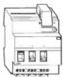
Art. no. MTN646991
For your safety
▲ ▲ DANGER
HAZARD OF ELECTRIC SHOCK, EXPLOSION, OR ARC FLASH
Safe electrical installation must be carried out only by skilled professionals. Skilled professionals must prove profound knowledge in the following areas:
- Connecting to installation networks
- Connecting several electrical devices
- Laying electric cables
- Connecting and establishing KNX networks
• Safety standards, local wiring rules and regulations
Failure to follow these instructions will result in death or serious injury.
CAUTION
The device may be damaged!
- Only operate the device according to the specifications stated in the Technical data.
- All the devices that are installed next to the binary input must be equipped with basic insulation at the very least.
Failure to follow these instruction can result in equipment damage.
Control unit introduction
The control unit 0-10 V REG-K/3-gang with manual mode dims and switches fluorescent lamps using electronic ballasts with a 0-10 V/1-10 V interface and LV halogen lamps using transformers with a 0-10 V/1-10 V interface.

The control voltage range can be set with the ETS via a parameter.
You can also manually switch the connected loads with the manual switches on the control unit without bus voltage.
The control unit has a bus coupler. It is installed on a DIN rail acc. to EN 60715, with the bus connection made via a bus connecting terminal. A data rail is not required.
Connections, displays and operating elements
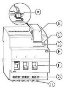
Ⓐ Bus connecting terminal
© Cable cover
© Programming button
⑭ Programming LED (red)
© Operating LED "RUN" (green)
F Manual switch
⑤ Channel terminals for load voltage
⑧ Outputs 1-10 V
Installing the control unit
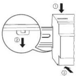
① Set the control unit onto the DIN rail.
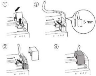
② Connect KNX.

WARNING
Risk of fatal injury from electrical current. The device could become damaged.
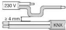
Safety clearance must be guaranteed in accordance with IEC 60664-1. There must be at least 4 mm between the individual cores of the 230 V supply cable and the KNX line.

WARNING
Risk of fatal injury from electrical current. The device could become damaged.
Disconnect the mains voltage before connecting the device to the load.
Terminals may not be inserted under load.
③ Connect the bus voltage.
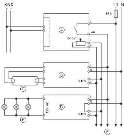
Ⓐ Control unit
⑧ Electronic ballast with 0-10 V/1-10 V interface
© Fluorescent lamp
⑭ Electronic transformer with 0-10 V/1-10 V control input
© LV halogen lamps
⑤ To other devices with 0-10 V/1-10 V interface
④ Connect the load.
⑤ Connect the load voltage.
Putting the actuator into operation
① Press the programming button.
The programming LED lights up.
② Load the physical address and application into the device from the ETS.
The programming LED goes out.
The operating LED lights up: The application was loaded successfully, the device is ready for operation.
Technical data
Supply from KNX: DC 24 V / approx. 17.5 mA
Insulation
voltages: AC 4 kV bus/mains voltage and
bus/0-10 V
AC 4 kV 0-10 V - mains voltage
Switch contact: Make contact, floating
Connection data for each channel:
Nominal current: 16 A, inductive cos φ = 0.6
Incandescent lamps: AC 230 V, 3600 W
Halogen lamps: AC 230 V, 2500 W
LV halogen lamps: max. 2000 VA via electronic transformers
Fluorescent lamps: AC 230 V, 5000 W,
uncompensated
AC 230 V, max. 2500 VA
parallel-compensated
Capacitive load: AC 230 V, 3600 W, 200 μF
Protection: The switch contact must be protected by a 16 A series-connected circuit-breaker.
Service life: > 50,000 switching cycles at nominal load
0-10V/1-10V
Interface: 0-10 V for dimming electronic ballasts
Loading capacity: max. 100 mA (max. 50 electronic ballasts, depending on EB)
Min. control voltage: 0 V
Ambient temperature
| Operation: | -5 °C to +45 °C |
| Storage: | -25 °C to +55 °C |
| Transport: | -25 °C to +70 °C |
Max. humidity: 93 %, no moisture condensation
Environment: Can be used at up to 2000 m above sea level (MSL)
Operating elements: 1 programming button 1 manual switch per channel
Display elements: 1 red LED: programming check
1 green LED: ready for
operation, "RUN"
Connections
| Bus: | via two 1 mm pins for bus connecting terminal |
Live conductor and
| switch output: | 3-gang screw terminals for max. 2.5 mm ^2 |
1-10 V output: 2-gang pluggable screw terminals for max. 2.5 mm ^4
EC directives: complies with Low-Voltage Directive 73/23/EEC, complies with EMC Directive 89/336/EEC
Device width: 4 modules = approx. 72 mm
Schneider Electric -Contact
Schneider Electric Industries SAS
If you have technical questions, please contact the Cus-
tomer Care Centre in your country.
se.com/contact

UK Representative
Schneider Electric Limited
Stafford Park 5
Telford, TF3 3 BL, UK
- SpaceLogic KNX Control unit 0-10 V REG-K/3-gang with manual mode
- For your safety
- ▲ ▲ DANGER
- HAZARD OF ELECTRIC SHOCK, EXPLOSION, OR ARC FLASH
- CAUTION
- The device may be damaged!
- Control unit introduction
- Connections, displays and operating elements
- Installing the control unit
- WARNING
- Risk of fatal injury from electrical current. The device could become damaged.
- Putting the actuator into operation
- Technical data
- Schneider Electric -Contact
Brand : SCHNEIDER
Model : MTN646991
Category : Unité de contrôle KNX