
WDE002482 - Uncategorized SCHNEIDER - Free user manual and instructions
Find the device manual for free WDE002482 SCHNEIDER in PDF.


| Product Type | Countdown Timer (10 A) |
| Brand | Schneider |
| Model | WDE002482 |
| Nominal Voltage | AC 230 V - 50 Hz |
| Nominal Current | 10 A |
| Power Ratings (resistive) | 2300 W |
| Power Ratings (LED) | 200 W |
| Power Ratings (capacitive) | 1350 VA |
| Power Ratings (inductive) | 1000 VA |
| Overtravel Time Range | 5 minutes to 8 hours |
| Default Overtravel Time | 5 minutes |
| Modes | Countdown, Infinite (on/off), Trigger |
| Status LED | Integrated red LED |
| Extension Connection | Single push-button, max 50 m cable |
| Terminals | Screw terminals for max 2×2.5 mm² |
| Fuse Protection | 10 A circuit breaker |
| Installation | By skilled professionals only |
| Safety | Disconnect power before servicing; risk of electric shock |
| Frame Required | Yes, corresponding design frame |
| Manual Languages | English, Norwegian, and others available on request |
Frequently Asked Questions - WDE002482 SCHNEIDER
User questions about WDE002482 SCHNEIDER
0 question about this device. Answer the ones you know or ask your own.
Ask a new question about this device
Download the instructions for your Uncategorized in PDF format for free! Find your manual WDE002482 - SCHNEIDER and take your electronic device back in hand. On this page are published all the documents necessary for the use of your device. WDE002482 by SCHNEIDER.
USER MANUAL WDE002482 SCHNEIDER
flowchart
graph TD
    A["Light Bulb"] --> B["Clock"]
    B --> C["Directional Arrow ①"]
    C --> D["Clock"]
    D --> E["Directional Arrow ②"]
    E --> F["Clock"]
    F --> G["Directional Arrow ③"]
    G --> H["Clock"]
    H --> I["Directional Arrow ④"]
    I --> J["Clock"]
    J --> K["Directional Arrow ⑤"]
flowchart
graph TD
    A["Light"] --> B["Rectangle"]
    C["Light"] --> B
    D["Light"] --> B
    E["Light"] --> B
    F["Light"] --> B

Tidsur med nedtelling 10 A
Nødvendig tilbehør
Komplichteres mod
• Hamme, passende ollommy
For din sikkerhet
FARE
FARE FOR ELEKTRISK STBT, EKSPLOSION ELLER OVERLEDNING
Sikre elektrunstallsgorer må uelukende utlare av autonsere installarser. De autonserte installatenne må hain gaarde survasp innen felgende om åder:
• Tilding II installations network
Email fryakapp, thegraser
BUTK makes 57 gm
25 A. w. tormakka
10 A. 2009-10
157
- Integrated status LED
Instalination:
• Gérglet 5 minuiter oil Ulmur (standardinsläng 5 minuiter)
• Oxycholone, Piaximano
• 1. Beningo/Box: Start with score 1max
Montering av timern
→→
⑧ Vekansek stierjahrande hyckknapp vid biappertenszulung (il-val)
Mierstrom: 10 A, cheap = 0.6
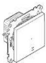
WDE002482, WDE003482, WDE004482
| LED 200 W | 1350 VA | M) 1000 VA |
| C=3 2200 W | C 10 A, 140μF | |
| 2000 W | 200 W | |
| 500 VA |
flowchart
graph TD
    A["Light Bulb"] --> B["Clock"]
    B --> C["Light Bulb"]
    D["Power Light"] --> E["Clock"]
    E --> F["Light Bulb"]
    G["Power Light"] --> H["Clock"]
    H --> I["Light Bulb"]
    J["Power Light"] --> K["Clock"]
    K --> L["Light Bulb"]
flowchart
graph TD
    A["Light Source"] --> B["Mirror"]
    B --> C["Light Source 1"]
    B --> D["Light Source 2"]
    B --> E["Light Source 3"]
ad aner-electric.com/contact
Necessary accessories
To be completed with
• Frame in corresponding design
For your safety
△ DANGER
HAZARD OF ELECTRIC SHOCK, EXPLOSION, OR ARC FLASH
Sale electrical installation must be came out only by skilled professionals. Skilled professionals must prove profound knowledge in the following areas
• Connecting to installation networks
• Connecting several electrical devices
• Laying electric cable
+ Safety standards, local wiring rules and regulations
tion
Failure to follow these instructions will result in death or serious injury.
DANGER
7.3 Risk of face injury from electric shock. The output may carry electrical current even when the load is enabled off.
- When working on the device Always discorrent the devices from the supply by means of the fuse in the incoming circuit.
Failure to observe these instructions will lead to death or serious injuries.
Getting to know the countdown timer 10 A
You can use the countdown time 10 A thereunder referred to as times to switch on or via, inducts at parasitive loads for a settaker over travel time.
Properties
- Manual switching off or restoring the overtravel time with an activated overtravel time.
• Operation with series unit (mechanical push-button)
• Integrated status LED
Settings
• Overmeal time: 5 minutes - 8 hours (default setting 5 minutes)
• Intrinsic mode: On/OFF switch
- Trigger mode: Switching of a second timer
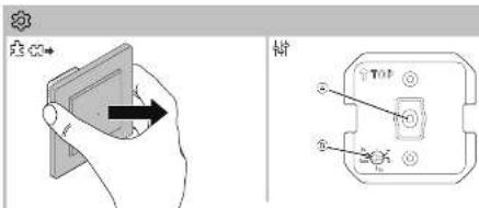
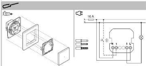
Mounting the timer
→
Mechanical push-buten air splen on unit connection (optional)
Setting the timer
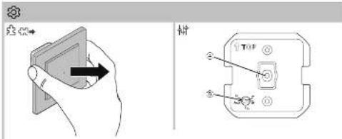
Removing the cover
→☆→☆☆
Put the frame off together with the operating elements.
Displays and operating elements
→
① Status LED (redi)
(7) Розенкимия
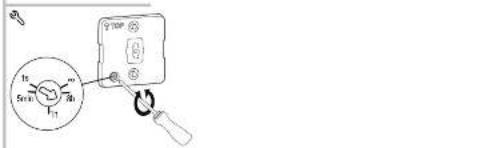
Setting functions
→→→→
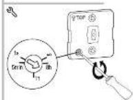
Overtravel time: 5min-1h-6h
Set an Infinitary adjustable overtravel time between 5 minutes and 8 hours. The further the potentiometer is turned and stockwise, the latter the selling increases
infinite mode: ∞
You can use the timer like a normal switch in infinite mode. Loads can only be switched off manually.
Trigger mode: 1s
Using a timer in trigger mode, you can operate a second timer externally and switch connected leads.
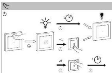
Operating the timer
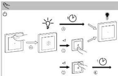
Operating the timer locally
P_2 (1)
Switch on this time for the duration of the set cross- based time (1).
The time automatically switches off after overtravel time (i) has elapsed.
Switch all the timer before overtravel time has disposed [c].
Connected mode and the LED switch are set off with the timer.
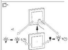
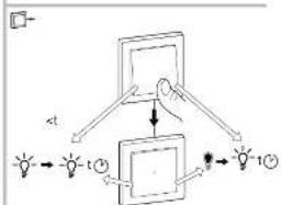
(1) Restart the activated overtravel time (i) before it pauses (2).
Operating the timer using an extension unit
→
Using a mechanical push-button connected to the extension and connection, switch the timer on or restart the activated movement time before it has elapsed (<1).
What should I do if there is a problem?
Connected load does not switch on:
- Check the power supply.
• Switch the timer off and back on again
- Check the load
- In the case of an external push-button, check the wi-
ng
Technical data
Nominal voltage: AC 230 V - 50 Hz
Nominal power
V - 30 Hz
500
-
Connecting terminals: Screw terminals for
max.2×2.5mm
Extension unit: Single push-button, unlimited
number
max. 50 m
Fuse protection
TO A BRIAN BREAKER
Roma
10AX, b69φ = 0.5
Diagonal of the device separately from home-
in official collection port. Pre
resistance, cycling, processes people and the
Name: James B. Johnson, 2013
[Non-Text]
The Ground Truth image displays a single, solid horizontal line. According to Rule 2 (UNDERSCORE & LINE RULES), this is a stylistic or background line, not a placeholder underscore. Therefore, the OCR result must ignore it and output nothing or only meaningful text. The provided OCR content is "____", which consists of four underscores. This is an incorrect interpretation of the line as a placeholder, violating the rule that stylistic lines must be ignored. The OCR has hallucinated underscores where none should exist based on the GT's visual context. Hence, the OCR result is inconsistent with the Ground Truth.
Schneider Electric Industries SAS
If you have technical questions, please contact the Bus
kore: Care Centre in your country
schneider-electric component
- Nødvendig tilbehør
- For din sikkerhet
- FARE
- Montering av timern
- Necessary accessories
- For your safety
- Getting to know the countdown timer 10 A
- Mounting the timer
- Setting the timer
- Setting functions
- infinite mode: ∞
- Operating the timer
- What should I do if there is a problem?
- Technical data
- Schneider Electric Industries SAS
Brand : SCHNEIDER
Model : WDE002482
Category : Uncategorized